1
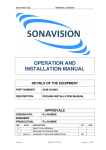
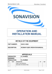
Sonavision Ltd.
Aberdeen, Scotland
OPERATION AND
INSTALLATION MANUAL
DETAILS OF THE EQUIPMENT
PART NUMBER:
2393-01-0001
DESCRIPTION:
TITAN SONAR OPERATING AND
INSTALLATION MANUAL
APPROVALS
ORIGINATOR:
ENGINEER:
PRODUCTION:
ISS
DATE
R.J HARDIE
R.J HARDIE
DESCRIPTION
BY
0
DRAFT FOR APPROVAL
1
RELEASE FOR PRODUCTION
CHK
2
Issue 3
2393-31-0020
Page 1 of 18
Sonavision Ltd.
3
31/03/10
Aberdeen, Scotland
UPGRADE TO NEW DOCUMENTATION
RH
4
5
The latest issue of this document is held in electronic form.
This is available from our website www.sonavision.co.uk
COPYRIGHT © SONAVISION LIMITED
AUGUST 2008
The copyright in this document is the property of Sonavision Limited. The document
is supplied by Sonavision Limited on the express terms that it may not be copied,
used, or disclosed to others except as authorised in writing by Sonavision Limited.
Sonavision Limited reserves the right to change, modify and update designs and
specifications as part of their ongoing product development programme.
TECHNICAL SUPPORT
Address
Sonavision Limited
Unit 12 Energy Development
Centre
Aberdeen Science and Energy
Park
Bridge of Don
Aberdeen
AB23 8GD
Scotland
Telephone
+44 (0)1224 707737
Fax
+44 (0)1224 827290
Email
[email protected]
Website
www.sonavision.co.uk
Issue 3
2393-31-0020
Page 2 of 18
Sonavision Ltd.
Aberdeen, Scotland
MAINTENANCE AND WARRANTY POLICY
Sonavision Limited warrants that its products are free from defects at the
time of delivery and subject to the conditions listed below, undertakes to
repair, or at its option replace, any product found to be defective in material
or workmanship within one year after delivery, whichever is less, to the
original purchaser by Sonavision Limited or its authorised representative.
CONDITIONS
1. Sonavision Limited must be immediately notified of any suspected defect
and if advised by Sonavision Limited, the equipment subject to defect
shall be returned to Sonavision Limited, freight prepaid.
2. This warranty does not cover defects which are caused as a result of
improper usage, repair, maintenance, alteration or installation unless
such activities have been undertaken by Sonavision Limited or its
authorised representative.
3. On completion of any warranty work, Sonavision Limited will return the
equipment, freight prepaid.
4. Sonavision Limited retains the sole right to accept or reject any warranty
claim.
SAFETY AND ENVIRONMENTAL STATEMENT
1. Lethal voltages are exposed within the control unit when the top cover is
removed. The unit should always be disconnected from the mains
supply before removing or operating any internal components.
2. The unit should be earthed at all times.
3. The unit contains electrostatically sensitive devices (ESSD). Appropriate
static protection should be used when handling subassemblies.
RELATED DOCUMENTS
Document Number
Issue 3
Document Title
2393-31-0020
Page 3 of 18
Sonavision Ltd.
Aberdeen, Scotland
TABLE OF CONTENTS
Section 1.0 INTRODUCTION AND SPECIFICATION
1.1
INTRODUCTION
1.2
SPECIFICATION
1.3
GENERAL ARRANGEMENT
Section 2.0 SYSTEM INSTALLATION
2.1
INTRODUCTION
2.2
PACKING / UNPACKING
2.3
INSTALLATION
2.4
ROUTINE MAINTENANCE
Section 3.0 DRAWINGS AND TABLES
3.1
TABLE 1 – CONNECTOR PIN-OUT
Section 4.0 SERVICE PROCEDURES
4.1
ASSEMBLY AND DIS-ASSEMBLY
4.2
COMMUNICATIONS INTERFACE
Issue 3
2393-31-0020
Page 4 of 18
Sonavision Ltd.
Aberdeen, Scotland
Section 1.0 INTRODUCTION AND SPECIFICATION
1.1 INTRODUCTION
The 2393 250/500 TITAN SONAR UNIT is part of a complete range of small
sonar units manufactured by Sonavision Ltd.
Operating depth is 1000 metres and the housing is manufactured from
stainless steel.
The operating frequency is fully tunable with coverage of 250 to 500 kHz.
The connector is compatible with that fitted to the Sonavision SV4000 sonar.
The unit requires to be supplied with nominally 24vdc power and
communicates to the surface control unit over two wires using RS485 half
duplex communication or over four wires using RS485 full duplex
communication. In addition, the unit can communicate using RS232 format
either for use with short cables or for fiber optic communications interfaces to
ROV systems.
1.2 SPECIFICATION
The subsea unit has a one atmosphere pressure vessel containing all the
electronic modules. A piezo-electric 1:3 composite transducer is located in the
transducer head which is mounted on the end of the drive shaft. The stepper
motor, head position sensor and slipring are all fitted in the motor housing
which is oil filled and pressure compensated by a diaphragm located on the
transducer head. The shaft seal is protected from contamination with a wiper
seal to minimize wear and damage on the main shaft seal when sand or other
contaminants are present.
The transducer head contains separate receive and transmit transducers and
a receive pre-amplifier is fitted close to the receive array to optimize signal to
noise ratio.
Acoustic Parameters
Operating Frequency:
250kHz to 500kHz fully tuneable
Transducer Beamwidth (nominal):
Horizontal:
Vertical:
2.1° at 500kHz
27° at 500kHz
Source Level (nominal):
210db re 1µPa at 1 m over the operating range
(Note that source level varies with supply voltage)
Pulse Length:
Bandwidth:
100µS
10kHz
Depth Rating:
Issue 3
1000 metres (Stainless Steel
Housing)
2393-31-0020
Page 5 of 18
Sonavision Ltd.
Aberdeen, Scotland
Temperature:
Operating:
Storage:
0°C to +30°C
-20°C to +50°C
Power Supply Voltage:
+20V to +32V D.C.
Weight:
In Air:
In Water:
4kg
2.4kg
Size:
226mm long (excluding connector)
90mm diameter (excluding head overhang)
Housing Material:
1000m unit
Stainless Steel Body
uPVC Transducer Head
Sonar Connector:
Sonavision SV4000 Proprietary Style
Communication:
RS485 Half Duplex (two wire)
RS422 Full Duplex (four wire)
RS232 (two wire & ground)
Communication Rate:
Downlink 57600 Baud
Uplink 57600 Baud
Or 9600 down / 57600 up (order option)
1.3 GENERAL ARRANGEMENT
The unit consists of three main modules:
•
The Transducer Head
•
The Motor Housing
•
The Pressure Housing
The transducer head contains the piezo-electric transducer elements and the
pre-amplifier printed circuit board. The motor housing contains the stepper
motor, the slipring and gear train mechanism. This unit is oil filled and
compensated to protect, lubricate and reduce wear on the shaft seal. The
motor housing contains glass / metal seal assemblies which allow transfer of
the electrical signals into the dry pressure housing containing the electronic
assemblies.
The chassis inside the pressure housing is a machined structural component
which holds a total of four printed circuit cards for controlling and processing
the sonar data. The chassis also provides the mechanism for locating the
pressure housing onto the motor housing end cap.
The printed cards inside the pressure housing are identified as follows:
•
•
•
TX / RX Board
TX / PA Board
CPU Board
Issue 3
2393-31-0020
Page 6 of 18
Sonavision Ltd.
•
Aberdeen, Scotland
PSU Board
The TX / RX board contains the entire low-level signal processing for the
sonar transmit and receive functions. The board is controlled by the CPU
board and interfaces to the TX / PA board.
The TX / PA board contains the power supply and power output circuits for
driving the transducer transmitting function.
The CPU board controls all the communication with the surface control unit
and the control for the transmit and receive functions. The circuit contains a
powerful DSP controller which processes both analogue and digital signals as
required. In addition, the board contains the output driver components for the
stepper motor.
The PSU board provides all power supplies required by the electronic
modules via DC/DC converters. These units accept a single DC input in the
range 20 to 32 vdc and generate several power supplies for the electronic
circuits on the other boards. The unit is protected against reverse supply
protection and an automatically resetting fuse is incorporated into the supply
line to the system to reduce the possibility of damage due to other circuit
faults.
The PSU board also contains the telemetry driver circuits which interface to
the surface control unit. Three types of communications protocol are provided
for a variety of situations. These can all be selected by jumpers on the board.
RS485 2 Wire - Most suitable for long umbilical cables with a single screened
twisted pair for sonar data.
RS485 4 Wire - Suitable for long cables where two screened twisted pairs are
available or for certain types of data multiplexers built into larger ROV's.
These are usually based on Fiber Optic Technology.
RS232 3 Wire (RXD, TXD & GND) - Suited for systems with built in data
telemetry systems which require RS232 protocol. This protocol is not suitable
for driving long cables but may be used in test installations with cable lengths
limited to a few tens of metres.
The line drivers are optically isolated from the rest of the sonar electronics to
reduce the possibility of interference and ground loops. A high value resistor
links the supply for the communications and the sonar electronics to reduce
the possibility of static voltage build up on the telemetry lines.
The Pressure Housing is a sealed structural component that attaches to the
motor housing and seals the electronics at one atmosphere against water
ingress. It is fitted with a Sonavision proprietary connector as fitted to the
SV4000 sonar range.
Issue 3
2393-31-0020
Page 7 of 18
Sonavision Ltd.
Aberdeen, Scotland
Section 2.0 SYSTEM INSTALLATION
2.1 INTRODUCTION
Section 2.3 details how installation of the sonar unit should be carried out
assuming the sonar unit is to be installed on an ROV, with power being
supplied locally to the sonar unit and communication being connected via an
umbilical. This is the conventional mode of operation for this unit.
Alternatively, power can be supplied from the surface control unit through a
multi-conductor umbilical cable. In this case, ensure that voltage drop in the
power conductors is kept to an absolute minimum.
2.2 PACKING / UNPACKING
The unpacking procedure is as follows:
Remove each unit from its carrying case.
Check that the contents of each case conform to the packing note.
Notify the manufacturer of discrepancies and/or transit damage.
Retain the carrying case for future shipment.
2.3 INSTALLATION
2393 Subsea Sonar Unit
To install the sonar unit on to an ROV, proceed as follows:
a) Remove the sonar unit from the carrying case and inspect for transit
damage, retain the carrying case for future shipment.
b) Test the sonar unit using a test cable and a power supply, if available or
supplied by Sonavision, and the PC or surface unit. This will prove that the
unit is operational before fitting into the ROV electrical system. If all is
satisfactory proceed with c).
c) Fit the unit to the ROV using a suitable and robust clamp, such that the
scribed line (or dimple) on the sonar transducer end cap is orientated to
forward or the connector exits to the rear. It is also advisable that a head
guard is also fitted around the head to avoid damage to the transducer
when the ROV hits an obstruction. The clamp should be fitted around the
motor housing where possible to avoid additional structural strain on the
pressure housing.
d) Ensure the cable whip is terminated to supply dc power and
communication in either half duplex or full duplex according to the factory
setting of the unit. Connection details for the are shown in TABLE 1.
e) Check and clean the sonar unit mating area of the connector then lightly
grease (silicon grease, Dow Corning MS4 silicon compound or equivalent)
the face of the cable whip connector and / or the o-rings.
f) Mate the connector and ensure that the screws are adequately tightened.
Issue 3
2393-31-0020
Page 8 of 18
Sonavision Ltd.
Aberdeen, Scotland
g) Connect the Surface Control Unit or PC at the surface end according to
the manual, if appropriate, and test the operation of the sonar unit. Should
the sonar unit not function correctly when installed on the vehicle remove
the unit and test again with the test cable and power supply. If the sonar
unit then works correctly there is probably an installation problem which
should be investigated.
The most likely problems include incorrect supply voltage and polarity of
the subsea power supply, incorrect choice of communications protocol and
incorrect polarity of the telemetry conductors.
Note that the sonar unit takes an initial surge current somewhat greater
than the steady state current. This can create problems when long cables
(or high resistance cables) are used between the power supply and the
sonar or when power supplies with in-built current limits are used.
2.4 ROUTINE MAINTENANCE
a.
Wash with fresh water after each recovery to remove sea water, mud,
silt and any other contaminants.
b.
Inspect the condition of the transducer head and mating connector and
cabling at regular intervals for oil leaks and/or signs of damage.
Issue 3
2393-31-0020
Page 9 of 18
Sonavision Ltd.
Aberdeen, Scotland
3.1 TABLE 1
Sonar Unit Connector wiring to 6-way Sonavision Connector
PIN
1
2
3
4
5
6
Issue 3
RS485
(two wire
mode)
RS485+
+24v
0v
RS485-
RS485
(four wire
mode)
RS485TxRS485Rx+
+24v
0v
RS485RxRS485Tx+
RS23
2
TXD
COM
+24v
0v
RXD
2393-31-0020
CABLE
WHIP
COLOURS
N/A
N/A
N/A
N/A
N/A
N/A
Page 10 of 18
Sonavision Ltd.
Aberdeen, Scotland
Section 4.0 SERVICE PROCEDURES
4.1 ASSEMBLY AND DIS-ASSEMBLY
The TITAN SONAR can be dismantled and serviced by experienced service
personnel. The following approach should be followed for disassembly and reassembly:
1. Removal of Housing
Remove the 3 off cap head screws holding the connector adapter in place.
Remove the connector adapter by pulling away from the main housing.
Remove the 2 off M3 cap head screws inside the face seal to release the
main pressure housing. Carefully pull the main housing off the motor housing
to avoid damage to the internal connector loom.
Remove the connector on the PSU PCB (the board with two large DC/DC
converters) to separate the housing and end cap assembly.
2. Removal of the Electronic Chassis
Remove the four pan head PCB retaining screws on the PSU PCB and the
TX/PA PCB. Remove the PCB's carefully by pulling away from the boards
underneath to disconnect the inter-board mating connectors.
Remove the two wiring looms to the end cap terminating in connectors on the
CPU board by carefully extracting the connectors from their sockets on the
board.
Remove the two wiring looms to the end cap terminating in connectors on the
TX / RX board and TX / PA board.
Remove the two M3 socket head cap screws which hold the chassis onto the
end cap. Ease the chassis away from the end cap avoiding straining the
wiring looms onto the end cap.
3. Disassembly of the Transducer Head
Note that the transducer head and motor housing are oil-filled and
compensated. Refilling with oil is a difficult task and the unit will be prone to
damage if any air bubbles are present in the oil after refilling. Servicing of the
transducer head and motor housing should only be undertaken by skilled
personnel.
Remove the 6 off M3 cap head screws holding the top cover onto the
transducer head. Hold the unit over a container to catch the oil which will spill
after the top cover and the diaphragm are removed.
Disconnect the pre-amplifier PCB connectors and remove by releasing the 2
off screws holding it in place.
Remove the 4 off cap head screws in the base of the transducer head and
remove the transducer head from the drive shaft.
4. Disassembly of the Motor Housing
Disassembly of the motor housing will lead to a loss of all the compensating
oil. Re-filling with oil is a difficult task. The use of a vacuum chamber is to be
recommended.
Issue 3
2393-31-0020
Page 11 of 18
Sonavision Ltd.
Aberdeen, Scotland
The motor housing should only be removed once the top cover and
diaphragm have been removed.
Remove the 2 off pozi-drive head screws on the face where the chassis is
attached. Note that these are “seal screws” and have a small o-ring under the
head. Do not lose or damage this o-ring. Carefully pull of the motor housing
from the end cap. Note that a wiring loom attaches the housing to the end cap
assembly. This can be disconnected at the connectors when the housing has
been sufficiently withdrawn.
5. Disassembly of the Gearbox Housing
The gearbox housing contains the gear components and slip-ring components
and the drive shaft with its bearings.
If the gearbox housing has to be disassembled, great care is needed to avoid
damage to the slip-ring components, in particular the fine wire brushes and
their holders.
Remove the 5 off M2.5 cap head screws around the periphery of the
aluminium gearbox housing and carefully pull away from the end cap. There
are no wiring looms between these assemblies.
The drive shaft can be removed by releasing the clamp nut on the end of the
shaft. This requires the use of a special tool which may be fabricated to suit
on-site. After removal of the nut, all the components associated with the drive
shaft can be removed one by one. Finally, the drive shaft can be removed
from the end cap by pressing through the ball bearing assembly.
6. Re-assembly of the Transducer Head and Motor Housing
Re-assembly is largely a reversal of the disassembly procedure but take note
of the following:
a. Always use a screw sealing compound such as Loctite 242 or 243 on all
screws to avoid their working loose in use.
b. The drive shaft main bearing must be fitted using Loctite grade 638 or
similar.
c. If the dust / grit seal is to be replaced, ensure that the face has been
pierced with a small drill to allow passage of water into the cavity between
it and the shaft o-ring. Failure to do this may cause the seal mechanism to
seize at depth or wear prematurely.
d. The drive shaft retaining nut must be fitted and tightened carefully using
the correct tool.
e. Ensure that the clutch spring providing pre-load on the gears is correctly
fitted and that the lay-gear assembly is free to rotate about its pivot screw.
f. When refitting the motor housing, take care to prevent the wiring loom
inside the housing from being crushed between the motor and the housing
end face.
g. When fitting the pozi-drive seal screws, check the small o-rings carefully
for cleanliness and damage. Tighten securely to a torque of approximately
1.25N-m.
Issue 3
2393-31-0020
Page 12 of 18
Sonavision Ltd.
Aberdeen, Scotland
Oil filling is best carried out in a vacuum chamber. If one is available, place
the transducer head / motor head assembly under approximately 20mm of oil
in a container, remove the slotted head seal screw in the motor housing end
plate and place in a vacuum chamber.
h. Pull a vacuum of at least 100mBar and leave until air bubbles cease to exit
the seal screw hole. Release the vacuum slowly and then repeat the
process several times.
i.
If a vacuum chamber is not available, oil filling can be attempted by using
a syringe to inject oil into the seal screw hole. In this case, the preamplifier chamber in the transducer head should first be filled. This is
necessary because the oil path into the gearbox housing is very small and
gravity is insufficient to ensure that oil will flow down into the pre-amplifier
chamber. Since it is more difficult to remove air from the assembly without
a vacuum chamber, considerable time should be given to allow air to rise
through the oil.
j.
Once the assembly is full of oil, replace the seal screw tightly to a torque of
approximately 2.4N-m and wash off excess oil from the assembly using
methylated spirits or a similar solvent. Do not use aggressive solvents
such as Acetone or Trichlorethylene.
7. Replacement of the electronic chassis
Replacement is simply a reversal of the disassembly instructions, ensuring
that all screws are sealed and connectors and wires are correctly inserted,
routed and undamaged.
8. Re-assembly of the Housing
The housing replacement is a reversal of the disassembly instructions.
Carefully clean all O- rings and mating surfaces and inspect for damage.
Lightly smear with Silicone Grease before installation.
Re-connect the housing wiring loom to the PSU PCB connector. The
connector is polarised to assist in inserting the correct way round.
The housing is intended to be fitted so that the wires from the housing
connector lie along the PSU PCB and have been routed during manufacture
in that way. Avoid allowing the wires to bunch up in the base of the housing
whilst inserting the electronic assembly.
When the wires are correctly routed, push the end cap into the housing, after
checking the o-rings.
Locate the chassis studs through the two holes in the housing and centralise.
Insert the seal screws (or M3 cap head screws) and tighten gently to draw the
end cap fully into the housing. DO NOT OVERTIGHTEN.
Replace the Sonavision proprietary connector adapter.
4.2 COMMUNICATIONS INTERFACE
INTRODUCTION
Issue 3
2393-31-0020
Page 13 of 18
Sonavision Ltd.
Aberdeen, Scotland
The TITAN sonar is provided with the means to operate using one of three
modes of communications with the surface control unit.
The available protocols are:
RS485 2 wire (half duplex)
RS485 4 wire (full duplex)
RS232 3 wire
The user can change the format of the communications by changing links
within the sonar unit.
The data rate (baud rate) for the sonar units is set in manufacture and cannot
be changed by the user. The data rate may be either 57600 baud in both
directions to maintain compatibility with the MERCURY sonar. Alternatively,
the data rate may be 9600 baud down and 57600 baud up to maintain
compatibility with the SV4000 range of sonar’s. Other data rates can be
provided as options if specified at time of order or if the sonar is returned to
Sonavision for modification.
DESCRIPTION OF THE OPTIONS
RS485 2 WIRE COMMUNICATIONS
RS485 2 wire is the conventional communications protocol for small to
medium size ROV’s which have screened twisted pairs available for optional
equipment. A single twisted pair is used for both directions of communication
and therefore transmit and receive are interleaved. RS485 is generally
accepted as being capable of at least 1000 metre operation over a reasonable
quality twisted pair. If a high quality (generally large conductor crossectional
area coupled with high quality insulation) twisted pair is used then greater
distances are achievable.
RS485 communications requires that the cable be correctly terminated at
each end. Link 6 & 7 when fitted, terminate the sonar end of the line with 120ohm resistors. This is acceptable for most types of screened twisted pair
cable.
Ultimately, maximum transmission distance depends upon signal loss in the
cable versus noise in the system (providing the lines are correctly terminated
to minimise reflections). A correctly terminated screen around the twisted pair,
whilst not essential for operation, will improve signal to noise ratio and
therefore quality of data communications. Note that the screen must be
carefully terminated to a good ground point, generally at one end of the cable
only.
RS485 4 WIRE COMMUNICATIONS
Issue 3
2393-31-0020
Page 14 of 18
Sonavision Ltd.
Aberdeen, Scotland
RS485 4 wire communication is available, but is rarely used since
performance improvements are marginal only. Occasionally, this format is
used with an ROV fitted with optical fibre multiplexor units.
The same comments apply to 4 wire as above where appropriate.
RS232 COMMUNICATIONS
RS232 communications is a new feature of the Sonavision range of sonars. It
allows a sonar to be directly connected to a COM port on a PC without any
interface box or hardware. This truly provides the concept of a “SONAR on a
DISK”. RS232 communications are severely limited in their transmission
distance and, depending on the type of cable used, the maximum can be as
little as a few tens of metres.
The main reason for the introduction of this option is to allow easy interface to
optical fibre multiplexers in larger vehicles whilst providing the client with the
option of using a stand-alone PC instead of a dedicated sonar control unit.
There are limitations in the COM port specifications of some PC’s (particularly
Laptops) and the data rate of the Sonavision sonar’s is generally set at 57600
baud unless otherwise specified to maintain compatibility with different PC
formats.
For long distance communications (i.e. ROV’s with long umbilical using
twisted pair channels for the sonar) and when using a simple PC as the
surface unit, an optional RS485 / RS232 converter can be supplied. The sonar
is set for RS485 communications and the data converter plugs directly into the
PC COM port. Two wire twisted pair data connection is then made between
the sonar and the data converter.
CHANGING THE COMMUNICATIONS PROTOCOL
Changing the protocol requires that the sonar unit is opened to gain access to
the printed circuit boards. This is carried out by following the procedures in
section 4.1 of this manual. This should only be attempted by an experienced
person since poor workmanship which leads to failure of the sonar unit will not
be covered by the manufacturers warranty.
The links which require changing are on the PSU board. This is the outer
board to which the connector on the housing mates. It also has two large
electronic modules in the centre which are easily recognizable.
The following diagrams show how links 1 to 7 should be set for the three
different communications protocols.
Issue 3
2393-31-0020
Page 15 of 18
Sonavision Ltd.
Issue 3
Aberdeen, Scotland
2393-31-0020
Page 16 of 18
Sonavision Ltd.
Issue 3
Aberdeen, Scotland
2393-31-0020
Page 17 of 18
Sonavision Ltd.
Aberdeen, Scotland
END OF DOCUMENT
Issue 3
2393-31-0020
Page 18 of 18