1
User’s
Manual
Models 436101/436102/436103/436104/436106
µR10000 Recorder
IM 04P01B01-01E
Yokogawa Electric Corporation
4th Edition
Foreword
Thank you for purchasing the YOKOGAWA µR10000 Recorder.
This manual describes the functions (excluding the communication functions), installation
and wiring procedures, operating procedures, and lists the handling precautions of the
µR10000 Recorder. To ensure correct use, please read this manual thoroughly before
beginning operation.
The following three manuals including this manual are available for the µR10000
Recorder.
• Electronic Manuals Provided on the Accompanying CD-ROM
Manual Title
Manual No.
Description
µR10000 Recorder
User’s Manual
IM 04P01B01-01E
This manual.
µR10000/µR20000
IM 04P01B01-17E
Communication Interface
User’s Manual
Explains the communication functions of the
µR10000 Recorder using Ethernet interface and
the RS-422A/485 communication interface.
• Paper Manual
Manual Title
Manual No.
Description
µR10000 Recorder
Operation Guide
IM 04P01B01-02E
Explains concisely the operations of the
µR10000 Recorder.
Notes
• The contents of this manual are subject to change without prior notice as a result of
continuing improvements to the instrument’s performance and functions.
• Every effort has been made in the preparation of this manual to ensure the accuracy
of its contents. However, should you have any questions or find any errors, please
contact your nearest YOKOGAWA dealer as listed on the back cover of this manual.
• Copying or reproducing all or any part of the contents of this manual without the
permission of Yokogawa Electric Corporation is strictly prohibited.
• The TCP/IP software of this product and the document concerning the TCP/IP
software have been developed/created by YOKOGAWA based on the BSD
Networking Software, Release 1 that has been licensed from the University of
California.
Trademarks
• All the brands or names of Yokogawa Electric’s products used in this manual are
either trademarks or registered trademarks of Yokogawa Electric Corporation.
• Microsoft, MS-DOS, Windows, Windows NT, and Windows XP are either registered
trademarks or trademarks of Microsoft Corporation in the United States and/or other
countries.
• Adobe, Acrobat, and PostScript are trademarks of Adobe Systems incorporated.
• For purposes of this manual, the TM and ® symbols do not accompany their
respective trademark names or registered trademark names.
• Company and product names that appear in this manual are trademarks or registered
trademarks of their respective holders.
Revisions
1st Edition
2nd Edition
3rd Edition
4th Edition
December 2004
March 2005
August 2005
September 2006
4th Edition: September 2006 (YK)
All Rights Reserved, Copyright © 2004 Yokogawa Electric Corporation
IM 04P01B01-01E
i
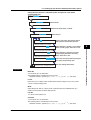
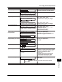
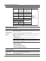
Recorder’s Version and Functions Described in This
Manual
The contents of this manual corresponds to the recorder with version 1.31.
µR10000 Versions and Functions
Version
Suffix Code
1.02 or earlier –
1.11
–
–
–
–
1.21
1.31
•
Added or Modified Functions
Reference
–
–
(Added)
(Added)
The printout/display format of the date can be changed.
Key operation to move the printer carriage near the
center position so that the ribbon cassette can be
replaced with the recorder turned ON (dot model)
(Changed) Selectable range of alarm values during linear
scaling (including 1-5V and SQRT) to -5% to
105% of the scale span.
Section 7.19
Section 3.4
Section 5.2
Section 6.16
/C3
(Changed) The procedure to set the start/end date and time of
Daylight Saving Time (DST) has been changed.
(Added)
Modbus/RTU slave protocol, two-wire system.
/C7
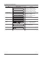
-2
/CC1
/H5x
/P1
–
–
/BT1
(Changed)
(Added)
(Added)
(Added)
(Added)
(Added)
(Added)
(Added)
Communication manual
Section 1.9
Section 1.2
Sections 2.5 and 12.7
Section 2.5
Section 1.9
Communication manual
Section 1.4
Users with the same user name cannot be registered.
Language support (German and French).
Calibration Correction.
Portable type.
24 VDC/AC power supply operation.
Customized menu.
Modbus register (40301 to 40348).
Header printout.
Communication manual
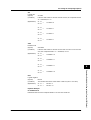
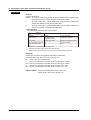
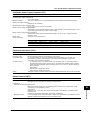
Checking the Version Number
You can check the version number on the System display.
The System display cannot be shown at the factory default condition.
First, register the System display to the display screen.
• Procedure of registering the System display to the display screen: See section 8.2.
• Procedure of displaying the System display: The screen switches each time the DISP key is pressed. Press the DISP
key repeatedly until System display is shown. The displayed contents on the System display switches every 3
seconds. Check the number shown by the “Version:” item.
Software (Sold Separately)
The table below shows the relationship between the RXA10 Configuration Software revisions and the µR10000
recorder versions.
Recorder version
R1.01
RXA10 Configuration
R2.01
Software revision
R3.01
1.02 or earlier
Yes
1.11
1.21
1.31
Yes
Yes
Yes
Yes
Yes
Yes
Limited
Yes
Yes:
Compatible
Limited: The new functions of the recorder cannot be configured from the RXA10.
Note
Set the recorder version in the RXA10 Configuration Software to display the setup items that
match the recorder’s functions.
ii
IM 04P01B01-01E
Safety Precautions
The general safety precautions described here must be observed during all phases of operation.
Safety Standards and EMC Standards
This recorder conforms to IEC safety class I (provided with terminal for protective grounding), Installation Category
II, Measurement Category II (CAT II), and EN61326-1 (EMC standard), class A (use in a commercial, industrial, or
business environment). This recorder is designed for indoor use.
About This Manual
• This manual should be read by the end user.
• Read this manual thoroughly and have a clear understanding of the product before operation.
• This manual explains the functions of the product. YOKOGAWA does not guarantee that the product will suit a
particular purpose of the user.
• Under absolutely no circumstances may the contents of this manual be transcribed or copied, in part or in
whole, without permission.
• The contents of this manual are subject to change without prior notice.
• Every effort has been made in the preparation of this manual to ensure the accuracy of its contents. However,
should you have any questions or find any errors or omissions, please contact your nearest YOKOGAWA
dealer.
Precautions Related to the Protection, Safety, and Alteration of the Product
• The following safety symbols are used on the product and in this manual.
“Handle with care.” To avoid injury and damage to the instrument, the operator must refer to the
explanation in the manual.
Protective ground terminal
AC
DC
“High temperature.” To avoid injury caused by hot surface, do not touch locations where this symbol
appears.
• For the protection and safe use of the product and the system controlled by it, be sure to follow the instructions
and precautions on safety that are stated in this manual whenever you handle the product. Take special note
that if you handle the product in a manner that violate these instructions, the protection functionality of the
product may be damaged or impaired. In such cases, YOKOGAWA does not guarantee the quality,
performance, function, and safety of the product.
• When installing protection and/or safety circuits such as lightning protection devices and equipment for the
product and control system or designing or installing separate protection and/or safety circuits for fool-proof
design and fail-safe design of the processes and lines that use the product and the control system, the user
should implement these using additional devices and equipment.
• If you are replacing parts or consumable items of the product, make sure to use parts specified by
YOKOGAWA.
• This product is not designed or manufactured to be used in critical applications that directly affect or threaten
human lives. Such applications include nuclear power equipment, devices using radioactivity, railway facilities,
aviation equipment, air navigation facilities, aviation facilities, and medical equipment. If so used, it is the user’s
responsibility to include in the system additional equipment and devices that ensure personnel safety.
• Do not modify this product.
IM 04P01B01-01E
iii
Safety Precautions
WARNING
• Use the Correct Power Supply
Ensure that the source voltage matches the voltage of the power supply before turning ON the power.
• Connect the Protective Grounding Terminal
Make sure to connect the protective grounding to prevent electric shock before turning ON the power.
• Necessity of Protective Grounding
Never cut off the internal or external protective earth wire or disconnect the wiring of the protective earth terminal.
Doing so invalidates the protective functions of the instrument and poses a potential shock hazard.
• Defect of Protective Grounding
Do not operate the instrument if the protective earth or fuse might be defective. Make sure to check
them before operation.
• Do Not Operate in an Explosive Atmosphere
Do not operate the instrument in the presence of flammable liquids or vapors. Operation in such
environments constitutes a safety hazard.
• Do Not Remove Covers
The cover should be removed by YOKOGAWA’s qualified personnel only. Opening the cover is
dangerous, because some areas inside the instrument have high voltages.
• External Connection
Connect the protective grounding before connecting to the item under measurement or to an external
control unit.
• Damage to the Protective Structure
Operating the recorder in a manner not described in this manual may damage its protective structure.
Portable Type (/H5x Option)
• Use the Correct Power Supply
Ensure that the power supply is within the maximum rated voltage range of the provided power cord
before connecting the power cord.
• Use the Correct Power Cord and Plug
To prevent electric shock or fire, be sure to use the power cord supplied by YOKOGAWA. The main
power plug must be plugged into an outlet with a protective earth terminal. Do not disable this protection
by using an extension cord without protective earth grounding.
• Connect the Protective Grounding Terminal
The power cord for the µR10000 is a three-prong type power cord. Connect the power cord to a
properly grounded three-prong outlet.
Exemption from Responsibility
• YOKOGAWA makes no warranties regarding the product except those stated in the WARRANTY that is
provided separately.
• YOKOGAWA assumes no liability to any party for any loss or damage, direct or indirect, caused by the user or
any unpredictable defect of the product.
Handling Precautions of the Software
• YOKOGAWA makes no warranties regarding the software accompanying this product except those stated in
the WARRANTY that is provided separately.
• Use the software on a single PC.
• You must purchase another copy of the software, if you are to use the software on another PC.
• Copying the software for any purposes other than backup is strictly prohibited.
• Please store the original media containing the software in a safe place.
• Reverse engineering, such as decompiling of the software, is strictly prohibited.
• No portion of the software supplied by YOKOGAWA may be transferred, exchanged, sublet, or leased for use
by any third party without prior permission by YOKOGAWA.
iv
IM 04P01B01-01E
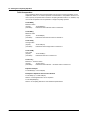
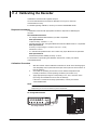
Checking the Contents of the Package
Unpack the box and check the contents before operating the recorder. If some of the
contents are not correct or missing or if there is physical damage, contact the dealer
from which you purchased them.
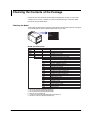
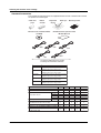
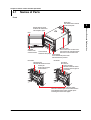
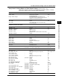
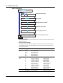
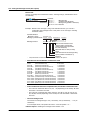
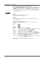
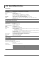
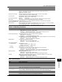
Checking the Model
A name plate is affixed to the recorder. Check that the model name and suffix code given
on the name plate on the rear panel match those on your order.
STYLE
MODEL
SUFFIX
SUPPLY
FREQUENCY
NO.
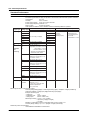
MODEL and SUFFIX Code
Model
436101
436102
436103
436104
436106
Suffix Code
Optional Code
-2
/A1
/A2
/A3
/C3
/C7
/F1
/H2
/H3
/H5D
/H5F
/H5R
/H5J
/H5H
/M1
/N1
/N2
/N3
/P1
/R1
/CC1
/BT1
1
2
3
4
5
6
7
IM 04P01B01-01E
Description
µR10000 1 pen recorder
µR10000 2 pen recorder
µR10000 3 pen recorder
µR10000 4 pen recorder
µR10000 6 dot recorder
English/German/French & deg F/DST
Alarm output relay 2 points1
Alarm output relay 4 points1
Alarm output relay 6 points1, 2
RS-422A/485 interface3
Ethernet (10BASE-T) interface3
Fail/Chart end detection and output2
Clamped input terminal4
Non-glare door glass
Portable type Power cord UL, CSA st'd7
Portable type Power cord VDE st'd7
Portable type Power cord AS st'd7
Portable type Power cord BS st'd7
Portable type Power cord GB st'd7
Mathematical function
Cu10, Cu25 RTD input
3 legs isolated RTD4, 5
Expansion inputs6
24 VDC/AC power supply7
Remote control 5 points
Calibration correction
Header printout
/A1, /A2, and /A3 cannot be specified simultaneously.
/A3 and /F1 cannot be specified simultaneously.
/C3 and /C7 cannot be specified simultaneously.
/H2 and /N2 cannot be specified simultaneously.
Valid only on the model 436106.
14 types of input including Pt50 RTD, PR40-20, and Platinel TC.
/H5x and /P1 cannot be specified simultaneously.
v
Checking the Contents of the Package
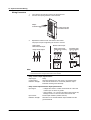
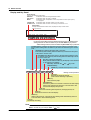
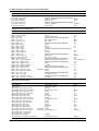
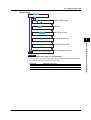
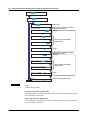
Standard Accessories
The standard accessories below are supplied with the recorder. Check that all contents
are present and undamaged.
Z-fold chart
paper
Ribbon
cassette
Disposable
felt pen
Manuals for the µR10000/µR20000
(CD-ROM)
/H5D
Plotter pen
Mounting bracket
µR10000 Recorder Operation Guide
IM 04P01B01-02E
/H5F
/H5R
/H5H
/H5J
One of these power cord types is supplied
according to the instrument’s suffix code
Part Number
Note
A1006WD
Provided when optional code /H5D is specified.
A1009WD
Provided when optional code /H5F is specified.
A1024WD
Provided when optional code /H5R is specified.
A1023WD
Provided when optional code /H5J is specified.
A1064WD
Provided when optional code /H5H is specified.
Maximum rated power voltage: 125V
Maximum rated power voltage: 250V
Maximum rated power voltage: 250V
Maximum rated power voltage: 250V
Maximum rated power voltage: 250V
Item
Z-fold chart paper
Ribbon cassette
Red
Disposable felt pen
Green
Blue
Violet
Purple
Plotter pen
Mounting bracket
(included with models without /H5x)
Power cord (included with /H5x)
Manuals for the µR10000/µR20000 (CD-ROM)
µR10000 Recorder Operation Guide
IM 04P01B01-02E
vi
1-Pen
1
1
1
2-Pen
1
1
1
1
3-Pen
1
1
1
1
1
4-Pen Dot Printing
1
1
1
1
1
1
1
1
-
2
2
2
2
2
1
1
1
1
1
1
1
1
1
1
1
1
1
1
1
IM 04P01B01-01E
Checking the Contents of the Package
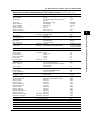
Optional Accessories (Sold Separately)
The optional accessories below are available for purchase separately. If you make an
order, make sure that all contents are present and undamaged.
For information about ordering accessories, contact the dealer from which you
purchased the recorder.
Item
Z-fold chart paper
Ribbon cassette
Red
Green
Blue
Violet
Purple
Disposable felt pen
Plotter pen
Mounting bracket
Shunt resistor
for the screw terminal (standard)
Shunt resistor
for the clamped input terminal (/H2)
Model
Quantity
(Part Number)
B9565AW
1
B9901AX
1
B9902AM
1
B9902AN
1
B9902AP
1
B9902AQ
1
B9902AR
1
B9900BX
2
415920
1
415921
1
1
415922
1
438920
1
438921
1
438922
Note
10 pcs.
3 pcs.
3 pcs.
3 pcs.
3 pcs.
3 pcs.
250 Ω ± 0.1%
100 Ω ± 0.1%
10 Ω ± 0.1%
250 Ω ± 0.1%
100 Ω ± 0.1%
10 Ω ± 0.1%
Software (Sold Separately)
Item
Note
Model
RXA10-01
µR10000 Configuration software
RXA10-02
With interface unit*
* You can use the Configuration Software if you install the interface unit to a recorder does not
include the communication function.
IM 04P01B01-01E
vii
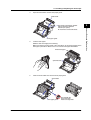
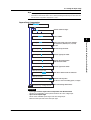
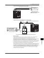
Checking the Contents of the Package
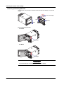
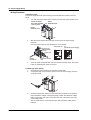
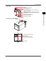
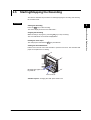
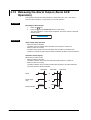
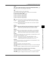
Removing the Packing Materials
Open the door, put your finger on the tab at the lower left of the display, and open the
display.
Tab on the display
Open
Display
Open
Remove all packing materials.
• Pen Model
Hinge
• Dot Model
Hinge
CAUTION
To protect the hinges, do not apply vertical force on the display.
viii
IM 04P01B01-01E
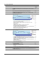
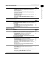
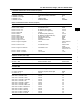
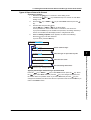
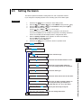
How to Use This Manual
This user’s manual consists of the following sections.
For details on communication functions, see the µR10000/µR20000 Communication
Interface User’s Manual (IM 04P01B01-17E) on the CD-ROM.
Chapter
Title and Description
1
Functional Explanation and Setup Guide
Describes the functions of the µR10000 Recorder and provides a function setup
guide. Refer to this chapter when you are unsure of the details of the function that
you are operating.
2
Before Using the Recorder
Describes the installation and wiring procedures.
3
Names of Parts and Run Operations
Describes the names of each part of the recorder and the daily operations.
4
Common Operations for Setting Functions and Setup Menu
Explains the recorder operation modes and the basic setup operations using keys. It
also provides menu configuration diagrams and lists of setup items.
5
Frequently Used Setup Operations (Setting Mode)
Describes how to change the input range, alarms, chart speed, etc.
6
Setup Operations for Convenient Functions (Setting Mode)
Describes the setup operations for convenient functions such as how to assign tags
to channels and how to set message strings that are to be printed.
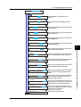
7
Setup Operations for Changing/Adding Functions (Basic Setting Mode)
Describes the setup operations for changing or adding functions such as setting the
recorder to detect sensor burnouts and changing the contents that are printed on the
chart paper.
8
Setup Operations for Changing the Displayed Contents
Describes how to select the display type suitable for the application.
9
Operations Related to the Computation Function (/M1 Option)
Describes all operations related to the computation function.
10
Troubleshooting
Describes error message and troubleshooting measures of the µR10000 Recorder.
11
Maintenance
Describes periodic inspection, calibration, pen adjustment/printer carriage
adjustment, and recommended replacement period for worn parts.
12
Specifications
Gives the specifications of the µR10000 Recorder.
Appendix Describes the printout contents.
Index
Note
•
•
IM 04P01B01-01E
This user’s manual covers information regarding the recorders with English as the display/
printout language (suffix code “2”).
For the procedure of setting the display/printout language, see section 7.14, “Changing the
Display/Printout Language.”
ix
How to Use This Manual
Conventions Used in This Manual
Unit
K ........ Denotes 1024. Example: 768 KB (file size)
k ........ Denotes 1000.
Safety Markings
The following markings are used in this manual.
Improper handling or use can lead to injury to the user or
damage to the instrument. This symbol appears on the
instrument to indicate that the user must refer to the user’s
manual for special instructions. The same symbol appears in
the corresponding place in the user’s manual to identify those
instructions. In the manual, the symbol is used in conjunction
with the word “WARNING” or “CAUTION.”
WARNING
Calls attention to actions or conditions that could cause serious
or fatal injury to the user, and precautions that can be taken to
prevent such occurrences.
CAUTION
Calls attentions to actions or conditions that could cause light
injury to the user or damage to the instrument or user’s data,
and precautions that can be taken to prevent such occurrences.
Note
Calls attention to information that is important for proper
operation of the instrument.
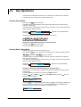
Subheadings
On pages that describe the operating procedures in Chapter 3 through 9, the following
symbols are used to distinguish the procedures from their explanations.
Bold characters denote keys or character strings that are displayed on the screen.
Example: Range, Unit
Procedure
Follow the numbered steps. All procedures are written with
inexperienced users in mind; depending on the operation, not
all steps need to be taken.
Explanation
This subsection describes the setting parameters and the
limitations on the procedures. It does not give a detailed
explanation of the function. For details on the function, see
chapter 1.
x
IM 04P01B01-01E
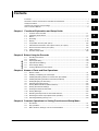
Contents
1
Foreword ......................................................................................................................................... i
Recorder’s Version and Functions Described in This Manual ......................................................... ii
Safety Precautions ......................................................................................................................... iii
Checking the Contents of the Package .......................................................................................... v
How to Use This Manual ................................................................................................................ ix
2
3
Chapter 1 Functional Explanation and Setup Guide
1.1
1.2
1.3
1.4
1.5
1.6
1.7
1.8
1.9
1.10
Overview of the Recorder ................................................................................................ 1-1
Measuring Input Section ................................................................................................. 1-2
Alarms .............................................................................................................................. 1-7
Recording ....................................................................................................................... 1-13
Display ........................................................................................................................... 1-24
Computation Function (/M1 Option) ............................................................................... 1-26
FAIL/Chart End Detection and Output Function (/F1 Option) ........................................ 1-29
Remote Control Function (/R1 Option) .......................................................................... 1-30
Other Functions ............................................................................................................. 1-32
Function Setup Guide .................................................................................................... 1-34
4
5
6
Chapter 2 Before Using the Recorder
2.1
2.2
2.3
2.4
2.5
2.6
Handling Precautions ....................................................................................................... 2-1
Installation ........................................................................................................................ 2-2
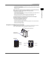
Input Signal Wiring ........................................................................................................... 2-4
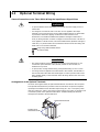
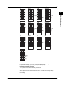
Optional Terminal Wiring .................................................................................................. 2-8
Power Supply Wiring ...................................................................................................... 2-11
Turning ON/OFF the Power Switch ................................................................................ 2-13
7
8
Chapter 3 Names of Parts and Run Operations
3.1
3.2
3.3
3.4
3.5
3.6
3.7
3.8
3.9
3.10
3.11
3.12
3.13
Names of Parts ................................................................................................................ 3-1
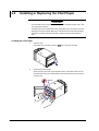
Installing or Replacing the Chart Paper ........................................................................... 3-4
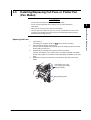
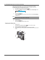
Installing/Replacing Felt Pens or Plotter Pen (Pen Model) .............................................. 3-7
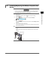
Installing/Replacing the Ribbon Cassette (Dot Model) .................................................... 3-9
Starting/Stopping the Recording .................................................................................... 3-11
Switching the Display Screen ........................................................................................ 3-12
Printing Measured Values (Manual Printout) ................................................................. 3-13
Printing the Recorder Settings ....................................................................................... 3-14
Clearing the Alarm Printout Buffer ................................................................................. 3-15
Printing Messages ......................................................................................................... 3-16
Resetting the Report Data of the Periodic Printout ........................................................ 3-17
Releasing the Alarm Output (Alarm ACK Operation) ..................................................... 3-18
Activating/Releasing the Key Lock ................................................................................. 3-19
9
10
11
12
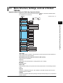
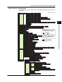
Chapter 4 Common Operations for Setting Functions and Setup Menu
4.1
4.2
4.3
Run Modes ....................................................................................................................... 4-1
Key Operations ................................................................................................................ 4-2
Menu Structure, Settings, and List of Default Values ....................................................... 4-5
App
Index
IM 04P01B01-01E
xi
Contents
Chapter 5 Frequently Used Setup Operations (Setting Mode)
5.1
5.2
5.3
5.4
5.5
Setting the Input Range ................................................................................................... 5-1
Setting the Alarm .............................................................................................................. 5-9
Setting the Unit on Scaled Channels ............................................................................. 5-12
Changing the Chart Speed ............................................................................................ 5-13
Setting the Date/Time .................................................................................................... 5-14
Chapter 6 Setup Operations for Convenient Functions (Setting Mode)
6.1
6.2
6.3
6.4
6.5
6.6
6.7
6.8
6.9
6.10
6.11
6.12
6.13
6.14
6.15
6.16
Setting the Trend Recording Interval (Dot Model) ............................................................ 6-1
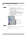
Setting the Filter (Pen Model) .......................................................................................... 6-2
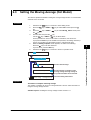
Setting the Moving Average (Dot Model) ......................................................................... 6-3
Setting Recording Zones for Each Channel (Zone Recording) ........................................ 6-4
Setting the Partial Expanded Recording .......................................................................... 6-5
Turning Trend Recording (Dot Model) and Periodic Printout ON/OFF for Each Channel 6-6
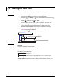
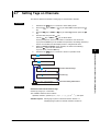
Setting Tags on Channels ................................................................................................ 6-7
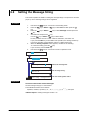
Setting the Message String .............................................................................................. 6-8
Setting the Secondary Chart Speed (Remote Control Function, /R1) ............................. 6-9
Setting the Alarm Delay Duration ................................................................................... 6-10
Setting the Brightness of the Display and Internal Light ................................................ 6-11
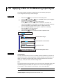
Applying a Bias on the Measuring Input Signal ............................................................. 6-12
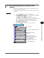
Performing Calibration Correction (/CC1 Option) .......................................................... 6-13
Setting Up Start Printout and End printout (/BT1 Option) .............................................. 6-15
Setting the Message Format (/BT1 Option) ................................................................... 6-19
Setting the Date/Time When Switching between Standard Time and DST ................... 6-21
Chapter 7 Setup Operations for Changing/Adding Functions (Basic Setting Mode)
7.1
7.2
7.3
7.4
7.5
7.6
7.7
7.8
7.9
7.10
7.11
7.12
7.13
7.14
7.15
7.16
7.17
7.18
7.19
7.20
7.21
7.22
7.23
7.24
7.25
xii
Changing the Auxiliary Alarm Function ............................................................................ 7-1
Changing the Integration Time of the A/D Converter ....................................................... 7-4
Setting the Burnout Detection Function of Thermocouples ............................................. 7-5
Setting the RJC Function on Channels Set to TC Input ................................................... 7-6
Changing the Channel Recording Color (Dot Model) ...................................................... 7-8
Recording by Compensating for the Pen Offset along the Time Axis (Pen Model) .......... 7-9
Turning Printouts ON/OFF(Selecting the Channel/Tag Printout and Turning ON/OFF the
Channel No., Alarm, Recording Start, New Chart Speed, Scale, and Pen Color
Printouts) ............................................................................................................ 7-10
Setting the Periodic Printout Interval and the Type of Data to Be Printed ..................... 7-12
Setting the Bar Graph Display Mode ............................................................................. 7-15
Setting the Key Lock Function ....................................................................................... 7-16
Enabling the Moving Average Function (Dot Model) ...................................................... 7-19
Enabling the Filter Function (Pen Model) ....................................................................... 7-20
Enabling the Partial Expanded Recording Function ...................................................... 7-21
Changing the Display/Printout Language ...................................................................... 7-22
Enabling the Bias, Low-Cut, Alarm Delay, Calibration Correction (/CC1 Option)
Functions ............................................................................................................ 7-23
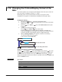
Changing the Time Printout Format ............................................................................... 7-25
Initializing the Settings ................................................................................................... 7-27
Assigning Functions to the Remote Control Input Terminals (/R1 Option) ..................... 7-28
Changing the Printout/Display Format of the Date ........................................................ 7-30
Selecting to Show/Hide the FUNC Key Menus .............................................................. 7-31
Selecting to Show/Hide Setting Mode Menus ................................................................ 7-33
Enabling/Disabling the Customized Menu ..................................................................... 7-35
Setting the Calibration Correction Function (/CC1 Option) ............................................ 7-38
Enabling Start Printout, End printout, and Message Format (/BT1 Option) ................... 7-40
Changing the Temperature Unit ..................................................................................... 7-42
IM 04P01B01-01E
Contents
1
Chapter 8 Setup Operations for Changing the Displayed Contents
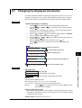
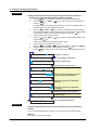
8.1
8.2
Key Operations for Changing the Displayed Information ................................................. 8-1
Changing the Displayed Information ................................................................................ 8-3
2
Chapter 9 Operations Related to the Computation Function (/M1 Option)
9.1
9.2
9.3
9.4
9.5
9.6
9.7
9.8
9.9
9.10
9.11
9.12
9.13
9.14
9.15
9.16
9.17
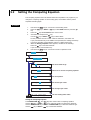
Starting/Stopping/Resetting the Computation .................................................................. 9-1
Setting the Computing Equation ...................................................................................... 9-2
Setting the Unit ................................................................................................................ 9-9
Setting the Constants Used in Equations ...................................................................... 9-10
Setting the Alarm ............................................................................................................ 9-11
Specifying the Timer Used in Statistical Calculations (TLOG) ....................................... 9-13
Setting Recording Zones for Each Channel (Zone Recording) ...................................... 9-15
Setting the Partial Expanded Recording ........................................................................ 9-16
Turning Trend Recording (Dot Model) and Periodic Printout (Including the Printout Using
the TLOG Timer) ON/OFF for Each Channel ..................................................... 9-17
Setting Tags on Channels .............................................................................................. 9-18
Setting the Alarm Delay Duration ................................................................................... 9-19
Setting the Timer Used in TLOG Computation and Periodic Printout ............................ 9-20
Changing the Channel Recording Color (Dot Model) .................................................... 9-23
Changing the Channel Assignments of Recording Pens (Pen Model) ........................... 9-24
Changing the Type of Report Data Printed in Periodic Printout ..................................... 9-25
Setting the Bar Graph Display Mode ............................................................................. 9-27
Setting the Procedure Taken When the Computed Result Is in Error ............................ 9-28
3
4
5
6
7
Chapter 10 Troubleshooting
10.1
10.2
A List of Error Messages ................................................................................................ 10-1
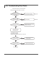
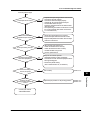
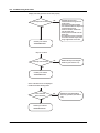
Troubleshooting Flow Charts ......................................................................................... 10-4
8
Chapter 11 Maintenance
11.1
11.2
11.3
11.4
11.5
11.6
11.7
Periodic Inspection ......................................................................................................... 11-1
Cleaning the Recorder ................................................................................................... 11-2
Replacing the Internal Light LED ................................................................................... 11-3
Calibrating the Recorder ................................................................................................ 11-4
Adjusting the Pen Position (Pen Model) ........................................................................ 11-6
Adjusting the Dot Printing Position (Dot Model) ............................................................. 11-8
Recommended Replacement Periods for Worn Parts ................................................. 11-10
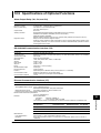
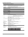
Chapter 12 Specifications
12.1
12.2
12.3
12.4
12.5
12.6
12.7
Input Specifications ........................................................................................................ 12-1
Alarm Function Specifications ........................................................................................ 12-3
Recording Function Specifications ................................................................................. 12-4
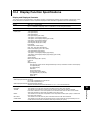
Display Function Specifications ..................................................................................... 12-7
Specifications of Optional Functions ............................................................................ 12-13
General Specifications ................................................................................................. 12-18
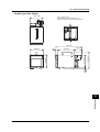
Dimensional Drawings ................................................................................................. 12-22
9
10
11
12
App
Appendix
Appendix 1
Appendix 2
Periodic Printout and Printout Using the TLOG Timer (/M1 Option) ................. App-1
Periodic Printout Interval .................................................................................. App-6
Index
IM 04P01B01-01E
xiii
Index
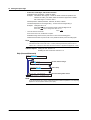
Chapter 1 Functional Explanation and Setup Guide
1.1
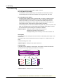
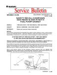
Overview of the Recorder
1
µR10000 Recorder
Recording example (dot model)
Alarms
For each channel, various alarms such as high limit alarm and low limit alarm can be
assigned to monitor the measured values. Alarm output relays can be used to output
contact signals when alarms occur (/A1, /A2, and /A3 options).
Recording
The measured results are recorded with pens or dots on a chart paper (trend recording).
The chart speed can be selected from 5 to 12000 mm/h on the pen model and 1 to 1500
mm/h on the dot model.
In addition to trend recording, various types of information can be printed or recorded on
the chart paper such as numeric measured values, alarm occurrence/release, and
predefined messages. Also, the recorder settings can be printed.
Internal Light
A light is provided for easier viewing of the recording area of the chart paper.
Display
Measured values can be displayed numerically or using bar graphs on the large display.
Also, alarm status and chart speed can be displayed.
Communication Function
Using the Ethernet communication interface (/C7 option) or the RS-422A/485
communication interface (/C3 option), the measured values on the recorder can be
output to a PC or a PC can be used to control the recorder.
This manual does not cover the communication functions. For details on communication
functions, see the µR10000/µR20000 Communication Interface User’s Manual (IM
04P01B01-17E) on the CD-ROM.
Other Main Functions
The computation function (/M1 option) can be used to perform various computations from
four arithmetic operations to statistical calculations on 8 and 12 computation channels on
the pen model and dot model, respectively. The computed results can be recorded.
The remote control function (/R1 option) can be used to control the start/stop and other
operations of the recorder by applying contact signals to the dedicated terminals.
The FAIL/chart end detection and output function (/F1 option) can be used to output contact
signals when errors are detected on the recorder or when the chart paper runs out.
For the procedure to set the functions, see section 1.10, “Function Setup Guide.”
IM 04P01B01-01E
1-1
Functional Explanation and Setup Guide
The µR10000 Recorder (hereafter referred to as the recorder) can be used to assign DC
voltage, 1-5V, thermocouple, RTD, and contact or voltage ON/OFF signal to channels for
measurement. The measured results are recorded with pens or dots on a chart paper
that is fed at a constant speed. The pen model can record up to 4 channels; the dot
model can record up to 6 channels.
1.2
Measuring Input Section
Input Section
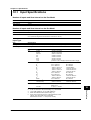
Number of Measurement Channels and Scan Interval
The recorder samples the input signals on the measurement channels at the scan
interval to obtain the measured values.
Model
Number of Channels
Scan Interval
1-pen model
2-pen model
3-pen model
4-pen model
Dot model
1
2
3
4
6
125 ms
125 ms
125 ms
125 ms
1 s (However, the scan interval is 2.5 s when the
integration time of the A/D converter is 100 ms.)
Input Type, Measurable Range, and Computation
The recorder can measure the following types of inputs.
Input Type
Measurable Range
DC voltage
DC voltage in the range of ±20 mV to ± 50 V
1-5V
See “1-5V” below.
Thermocouple Temperature range corresponding to each type: R, S, B, K, E, J, T, N, W, L, U,
and WRe
RTD
Temperature range corresponding to each type: Pt100Ω and JPt100Ω
ON/OFF input Contact input: Open contact is OFF (0). Closed contact is ON (1).
Voltage input: Less than 2.4 V is OFF (0). Greater than or equal to 2.4 V is ON (1).
Within ±6 V.
• 1-5V
1-5V is scaled to values in the appropriate unit to be used as measured values. Also,
the low-cut function (input less than 0% is fixed to 0% (scale left value)) can be used.
• Current Input
A shunt resistor is attached to the input terminal. The current signal is converted to a
voltage signal and measured. The measurable range is the range equivalent to the
“DC voltage” range indicated above after converting the current to the voltage signal.
Note
Three types of shunt resistors (250 Ω, 100 Ω, and 10 Ω) are available for current input (see
“Optional Accessories (Sold Separately)” on page vii). For example, a 250-Ω shunt resistor is
used to convert the signal to the range of 1 to 5 V for 4 to 20 mA input.
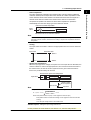
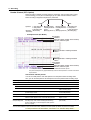
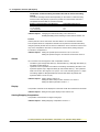
• Range Type, Measurable Range, and Recording Span
Various “range type” are available for the different types of inputs (for example
thermocouple type R). Each range type has a preset measurable range (0.0 to
1760.0°C for thermocouple type R). Measurement can be made by specifying an
arbitrary range within the measurable range as the input range. The measured values
in the input range are recorded on the chart paper. The range of measured values
that are recorded is called the recording span.
Measurable range (Thermocouple type R example)
Input range or
recording span
1760.0°C
1500.0°C (rightmost value of span)
300.0°C (leftmost value of span)
0.0°C
<Related Topics> Setting the input range: Section 5.1
For the procedure to set the functions, see section 1.10, “Function Setup Guide.”
1-2
IM 04P01B01-01E
1.2 Measuring Input Section
Channel set to delta computation
Input
value
Measured value
–
Measured value on the reference channel
Note
A channel whose input type is set to DC voltage, TC, or RTD can be designated as a
reference channel. However, channels set to scaling or square root computation cannot be
designated.
• Scaling
The input values are scaled to values in the appropriate unit to be used as measured
values.
Input value
10 V
Measured value
300.0°C
0V
−100.0°C
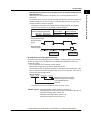
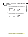
• Square Root Computation
When the input type is DC voltage, the square root of the input value is calculated, the
result is scaled to a value in the appropriate unit, and used as the measured value of
the channel. Also, the low-cut function (input less than a given measured value is
fixed to 0% (scale left value)) can be used.
Channel set to square root computation
Input value
√
Scaling
Measured value
Measured value
Result of square
root computation
Low-cut value
Input value
Note
The square root computation on the recorder uses the following formula.
Fx = ( Fmax - Fmin )
Vx - Vmin
Vmax - Vmin
+ Fmin
where Vmin (leftmost value of span) < Vmax (rightmost value of span)
Fmin (leftmost value of scale after scaling) < Fmax (rightmost value of scale after
scaling)
Vx is the input voltage and Fx is the scaled value
<Related Topics> Setting the input range: Section 5.1
For the procedure to set the functions, see section 1.10, “Function Setup Guide.”
IM 04P01B01-01E
1-3
1
Functional Explanation and Setup Guide
• Delta Computation
The value obtained by subtracting the measured value of another channel (called the
reference channel) from the input value of the channel set to delta computation is used
as the measured value of that channel. The reference channel must be assigned to a
channel whose channel number is less than that of the channel on which delta
computation is specified. The channel on which delta computation is specified is
automatically set to the same range type as the reference channel.
1.2 Measuring Input Section
• Bias
A given value (bias value) is added to the input value and used as the measured
value of that channel.
Biased channel
Input value
Measured value
+
Bias value
<Related Topics> Setting the bias: Sections 7.15 and 6.12
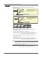
• Calibration Correction (/CC1 Option)
Corrects the measured value of each channel using segment linearizer approximation
and makes the resultant value the measured value of the channel. You can set
arbitrary correction values for 2 to 16 points of arbitrary measured values. Linear
approximation is used between two segment points. Correction values can be
assigned using revise values or absolute values.
Scale value
B5
Measured value
A5
A4
Correction
value
B3
B4
B2
A3
B1
A2
A1
Correction using
revise values
Measured value = A
Correction value = B – A
Correction using
absolute values
Measured value = A
Correction value = B
A1 to A5: Measured value (measured value before correction)
B1 to B5: Correction value (measured value after correction)
Calibration point
<Related Topics> Setting the calibration correction function: Sections 7.15, 7.23, and
6.13
Burnout Detection of Thermocouples
This function makes the recording go off the scale to the right or left when the
thermocouple burns out while measuring temperature with a thermocouple. This function
can also be used on 1-5V. The burnout detection function can be set for each channel.
By default, this function is disabled.
Note
For 1-5V, a burnout occurs when the input value is less than or equal to 0.2 V.
<Related Topics> Setting the burnout detection function: Section 7.3
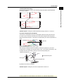
Reference Junction Compensation of Thermocouple Input
When measuring the temperature using a thermocouple, the reference junction
compensation on the recorder can be used. When using external reference junction
compensation, you can set the reference voltage. The reference junction compensation
can be set for each channel.
By default, the recorder is configured to use the internal reference junction compensation
function.
For the procedure to set the functions, see section 1.10, “Function Setup Guide.”
1-4
IM 04P01B01-01E
1.2 Measuring Input Section
1
Note
Example when using external reference junction compensation
External reference junction compensation
Recorder
(Hold the contact point of the thermocouple
and copper wire at T0°C)
Copper wire
Thermocouple
<Related Topics> Setting the reference junction compensation function: Section 7.4
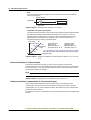
Noise Elimination from Input Signals
Filter and Moving Average
This function used to suppress the effects of noise that is riding on the signal. The pen
model and dot model are equipped with a filter function and a moving average function,
respectively. The function can be set for each measurement channel. However, it does
not operate on channels set to ON/OFF input.
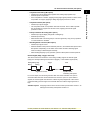
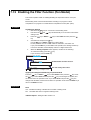
• Filter (Pen Model)
The filter is a low-pass filter. The time constant can be set to 2 s, 5 s, or 10 s.
Filter result (output for a step input)
Input
63.2% of the output value
Output response curve
(when using the filter)
2, 5, 10 s (time constant, the time it takes
to reach 63.2% of the output value)
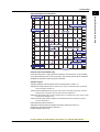
• Moving Average (Dot Model)
The average value of the m most recent values acquired at the scan interval is used
as the measured value of the channel. The number of moving-averaged data points
(m) can be set in the range 2 to 16. The figure below shows an example indicating the
operation of the buffer for the moving average computation when the number of
moving averaged data points is set to 5.
Buffer data for the
nth sampling time
Buffer data for the
n+1th sampling time
Buffer data for the
n+2th sampling time
Most recent data
Most recent data
1
10.0 mV
15.0 mV
10.0 mV
2
5.0 mV
10.0 mV
15.0 mV
3
0.0 mV
5.0 mV
10.0 mV
5.0 mV
4
–5.0 mV
0.0 mV
5
–10.0 mV
–5.0 mV
Deleted
Moving
average
0.0 mV
0.0 mV
Deleted
5.0 mV
8.0 mV
<Related Topics> Setting the filter: Sections 7.12 and 6.2
Setting the moving average: Sections 7.11 and 6.3
For the procedure to set the functions, see section 1.10, “Function Setup Guide.”
IM 04P01B01-01E
1-5
Functional Explanation and Setup Guide
When using external reference junction compensation, set an appropriate reference junction
compensation voltage. For example, if the reference junction temperature of the external
reference compensation is T0 °C, set the reference compensation junction voltage to the
thermoelectromotive force of the 0°C reference of T0 °C.
1.2 Measuring Input Section
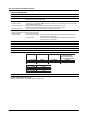
Integration Time of the A/D Converter
The recorder uses an A/D converter to convert the sampled analog signal to a digital
signal. By setting the integration time of the A/D converter to match the time period
corresponding to one cycle of the power supply or an integer multiple of one cycle, the
power supply frequency noise can be effectively suppressed.
The integration time of the A/D converter is selected according to the model from the
table below.
Model
Integration Time of the A/D Converter
Pen model
Select 16.7 ms (60 Hz), 20 ms (50 Hz), or Auto
Dot model
Select 16.7 ms (60 Hz), 20 ms (50 Hz), 100 ms or Auto
• If Auto is selected, the recorder detects the power supply frequency and automatically
selects 16.7 ms or 20 ms.
• If Auto is specified when using the 24-VDC power supply on a recorder with the 24VDC/AC power supply (/P1 option), the integration time is fixed to 20 ms (50 Hz).
• Because 100 ms is an integer multiple of 16.7 ms and 20 ms, this setting can be used
to suppress the power frequency noise for either frequency, 50 Hz or 60 Hz.
• The scan interval on the dot model is 1 s when the integration time is set to 16.7 ms or
20 ms and 2.5 s when the integration time is set to 100 ms.
<Related Topics> Setting the A/D integration time: Section 7.2
For the procedure to set the functions, see section 1.10, “Function Setup Guide.”
1-6
IM 04P01B01-01E
1.3
Alarms
1
Alarm Types
Number of Alarm Point Marks
Up to four alarms can be set for each channel.
Alarm Conditions
The eight conditions below are available. The character inside the parentheses is the
symbol used to denote each alarm on the recorder.
• High Limit Alarm (H)
An alarm occurs when the input value exceeds the alarm value.
• Low Limit Alarm (L)
An alarm occurs when the input value falls below the alarm value.
Low limit alarm
High limit alarm
Alarm
value
Alarm occurrence
Alarm release
Measured value
Measured Alarm release
value
Alarm value
Alarm occurrence
• Difference High Limit Alarm (h)*
An alarm occurs when the difference in the input values of two channels is greater
than or equal to the specified value.
• Difference Low Limit Alarm (l)*
An alarm occurs when the difference in the input values of two channels is less than
or equal to the specified value.
*
Can be specified on channels set to delta computation.
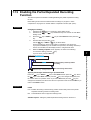
• High Limit on Rate-of-Change Alarm (R)
The rate-of-change of the measured values is checked over a certain time (interval).
An alarm occurs if the rate-of-change of the measured value in the rising direction is
greater than or equal to the specified value.
• Low Limit on Rate-of-Change Alarm (r)
The rate-of-change of the measured values is checked over a certain time (interval).
An alarm occurs if the rate-of-change of the measured value in the falling direction is
greater than or equal to the specified value.
High limit on rate-of-change alarm
Low limit on rate-of-change alarm
Change in the
measured value
Measured
T2
value
Measured T1
value
Amount of change
in the setting
| T2−T1 |
T1
Amount of change
in the setting
| T2−T1 |
T2
Change in the
measured value
t1
t2−t1
Interval
t2
Time
t1
t2−t1
t2
Time
Interval
The alarm value of the rate-of-change alarm is set using an absolute value. The
interval is derived using the following equation and set using the number of samples.
Interval = the scan interval × the number of samples
For the procedure to set the functions, see section 1.10, “Function Setup Guide.”
IM 04P01B01-01E
1-7
Functional Explanation and Setup Guide
This function generates an alarm when the measured data meets a certain condition.
The alarm occurrence/release can be recorded on the chart paper. The alarm status can
be displayed on the screen. Also, alarm output relays can be used to output contact
signals when alarms occur (/A1, /A2, and /A3 options).
1.3 Alarms
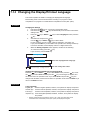
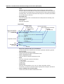
• Delay High Limit Alarm (T)
An alarm occurs when the measured value remains above the alarm value for a
specified time period (alarm delay period).
• Delay Low Limit Alarm (t)
An alarm occurs when the measured value remains below the alarm value for a
specified time period (alarm delay period).
Delay High Limit Alarm Example (T is the specified delay)
Measured value
X1
X2
X3
X4
Alarm value
T1
T
Alarm occurrence
Alarm release
• Alarm does not occur at T1, because the time period is shorter than the specified
alarm delay period (T).
• The measured value exceeds the alarm value at time X2, and the alarm occurs at
time X3 at which the specified alarm delay period elapses (the time when the alarm
occurs is the time at X3).
• The measured value falls below the alarm value at time X4, and the alarm is
released.
Note
•
•
The alarm detection operation is reset when a power failure occurs. The operation restarts
after the power recovers.
If the alarm value is changed while a delay alarm is occurring, the alarm is released if the
new alarm value does not meet the alarm condition.
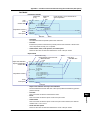
Alarm Hysteresis
Hysteresis can be specified to the values for activating and releasing the alarm. The
hysteresis applies only to high limit alarm (H) and low limit alarm (L). The hysteresis
width can be set in the range of 0.0% (Off) to 1.0% of the recording span in 0.1 steps.
The setting applies to all high limit alarms and low limit alarms. By default, the hysteresis
width is set to 0.5%.
Low limit alarm
High limit alarm
Alarm occurrence
Alarm
value
Measured
value
Alarm release
Hysteresis
(1% or less)
Measured value
<Related Topics>
Alarm release
Alarm value
Alarm occurrence
Setting alarms: Section 5.2
Setting the alarm delay function: Sections 7.15 and 6.10
Setting the alarm hysteresis: Section 7.1
For the procedure to set the functions, see section 1.10, “Function Setup Guide.”
1-8
IM 04P01B01-01E
1.3 Alarms
1
Alarm Indication
Non-hold
Hold
Alarm ACK
Alarm occurrence
Alarm
Alarm ACK
or
Alarm release
Blinking
Blinking
ON
ON
Alarm
indication
OFF
or
OFF
OFF
<Related Topics> Setting the non-hold/hold operation of the alarm indicator: Section 7.1
Alarm Recording
The alarm occurrence/release can be recorded on the chart paper. See section 1.4.
Alarm Output Relay (/A1, /A2, and /A3 Options)
Contact signals can be generated from alarm output relays when alarms occur. The
number of output relays is 2 (/A1), 4 (/A2), or 6 (/A3). The alarm output relays are
denoted as I01 to I06 on the recorder.
The following functions can be assigned to the alarm output relay.
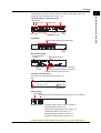
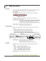
Diagnosis Output
The diagnosis output can be assigned to alarm output relay I01.
The relay is activated when there is an error in the plotter operation on the pen model,
when a burnout is detected, or when there is an error in the A/D converter. Output relay
I01 is normally energized and de-energizes when an error is detected (de-energized
operation and non-hold operation).
NO
C
Normal
NC
NO
C
NC
Malfunction
NO
C
NC
Power-OFF
NO: Normally Opened, C: Common, NC: Normally Closed
Note
If diagnosis output is enabled, I01 becomes a relay dedicated to diagnosis output.
<Related Topics> Setting the diagnosis output: Section 7.1
For the procedure to set the functions, see section 1.10, “Function Setup Guide.”
IM 04P01B01-01E
1-9
Functional Explanation and Setup Guide
The alarm status can be displayed on the screen. For details on the display, see section
1.5.
Non-Hold/Hold Operation of the Alarm Indication
The alarm indication can be set to operate in the following fashion when the alarm
condition is no longer met.
• Clear the alarm indication (non-hold).
• Hold the alarm indication until the alarm ACK operation is executed (hold).
The default setting is non-hold.
1.3 Alarms
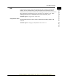
Reflash Alarm
When multiple alarms are assigned to one alarm output relay, this function notifies the
occurrence of subsequent alarms after the relay is activated by the first alarm. When
subsequent alarms occur, the output relay is released temporarily (approximately 500
ms).
The reflash alarm function is set to three output relays (I01, I02, and I03 (I01 and I02 for
the /A1 option)).
By default, the reflash alarm is disabled.
Alarm
Channel 1
Channel 2
Channel 3
Alarm output relay
(Reflash alarm ON)
Approx. 500 ms Approx. 500 ms
Alarm output relay
(Reflash alarm OFF)
Note
•
•
If the reflash alarm is enabled, I01 to I03 are set to reflash alarm operation. In this case, I01 to
I03 are set to OR operation and non-hold operation regardless of the settings specified in
“AND/OR Operation of Alarm Output Relays” and “Non-Hold/Hold Operation of Alarm Output
Relays” described below.
If diagnosis output is enabled, I01 is set to diagnosis output.
<Related Topics> Setting the reflash alarm: Section 7.1
For the procedure to set the functions, see section 1.10, “Function Setup Guide.”
1-10
IM 04P01B01-01E
1.3 Alarms
Channel 01
Alarm
Channel 02
AND
Alarm output relay
OR
The alarm output relays assigned to AND operation are specified as follows: “I01 (first
relay) to Ixx (where xx is the relay number).”
The default setting is “no AND relay.”
Note
•
•
If the reflash alarm is enabled, I01 to I03 are fixed to OR operation. Specifying AND
produces no effect.
If diagnosis output is enabled, I01 is set to diagnosis output. Specifying AND produces no
effect.
<Related Topics> Setting the AND operation: Section 7.1
Energized/De-energized Operation of Alarm Output Relays
You can select whether the alarm output relay is energized or de-energized when an
alarm occurs. If de-energized is selected, the status of the alarm output relay when an
alarm occurs is the same as the status that results when the recorder is turned OFF
(including power failures). The setting applies to all alarm output relays.
The default setting is energized.
Energize
NO
C
NC
De-energize NO
C
NC
When power is
turned OFF
NO
C
NC
NO
C
NC
When alarm is
not occurring
NO
NO
C
NC
C
NC
When alarm is
occurring
NO : Normally Opened, C : Common, NC : Normally Closed
Note
If diagnosis output is enabled, I01 is fixed to de-energized operation.
<Related Topics> Setting the energized/de-energized operation of alarm output relays:
Section 7.1
For the procedure to set the functions, see section 1.10, “Function Setup Guide.”
IM 04P01B01-01E
1-11
1
Functional Explanation and Setup Guide
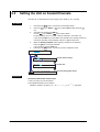
AND/OR Operation of Alarm Output Relays
When multiple alarms are assigned to one alarm output relay, the condition for activating
the alarm output relay can be selected from the following:
• AND: Activated when all assigned alarms are occurring simultaneously.
• OR: Activated when any of the specified alarms is occurring.
1.3 Alarms
Non-Hold/Hold Operation of Alarm Output Relays
The alarm output relay can be set to operate in the following fashion when the alarm
condition is no longer met.
• Turn off the relay output (non-hold).
• Hold the relay output until the alarm ACK operation is executed (hold).
The setting applies to all alarm output relays.
The default setting is non-hold.
Non-hold
Alarm occurrence
Hold
Alarm
ACK
Alarm
Alarm Alarm
ACK ACK
or
Alarm release
Activated
Alarm output
relay
Released
or
Note
•
•
If the reflash alarm is enabled, I01 to I03 are fixed to non-hold operation. Specifying Hold
produces no effect.
If diagnosis output is enabled, I01 is fixed to non-hold operation. Specifying Hold produces no
effect.
<Related Topics> Setting the non-hold/hold operation of alarm output relays: Section 7.1
Alarm ACK Operation
The alarm acknowledge (alarm ACK) operation releases all alarm indications and relay
outputs (/A1, /A2, and /A3 options) that are activated when the alarm indication or alarm
output relay is set to hold operation. This operation can be executed from the front panel
key.
<Related Topics> Alarm ACK operation: Section 3.12
For the procedure to set the functions, see section 1.10, “Function Setup Guide.”
1-12
IM 04P01B01-01E
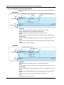
1.4
Recording
1
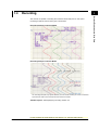
Functional Explanation and Setup Guide
The recorder is capable of recording the measured values with pens or dots (trend
recording) as well as various other types of information.
Recording Example on the Pen Model
Recording Example on the Dot Model
The recording examples may appear differently from the actual recording as a result of functional
improvements made on the recorder after this manual was written.
<Related Topics> Starting/Stopping recording: Section 3.5
For the procedure to set the functions, see section 1.10, “Function Setup Guide.”
IM 04P01B01-01E
1-13
1.4 Recording
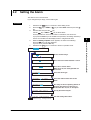
Trend Recording
The measured values are printed within a width of 100 mm.
Recording Method (Pen Model)
• The measured value is updated every scan interval and continuously recorded.
• The recording colors in order from channel 01 are red, green, blue, and violet.
Recording Method (Dot Model)
• The most recent measured value is recorded with a dot every dot printing interval.
The dot printing interval is in the range of 10 s to 90 s. There are two recording
methods from which you can select. One method automatically adjusts the dot
printing interval according to the chart speed so that the dots do not overlap. The
other method records at the fastest dot printing interval at all times.
• The recording colors in order from channel 01 are purple, red, green, blue, brown, and
black. The recording color of each channel can be changed among these six colors.
• For each channel, trend recording can be enabled or disabled.
<Related Topics> Setting the trend recording interval: Section 6.1
Changing the recording color: Section 7.5
Enabling/Disabling trend recording for each channel: Section 6.6
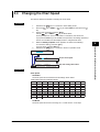
Chart Speed
On the pen model, the chart speed can be selected from 82 settings in the range of 5 to
12000 mm/h.
On the dot model, the chart speed can be set in the range of 1 to 1500 mm/h in 1-mm
steps.
The default setting is 20 mm/h.
<Related Topics> Setting the chart speed: Section 5.4
Zone Recording
A recording zone is assigned to each channel. This function is useful such when the
recording results overlap making them difficult to be viewed.
Zone 1
Zone 2
Zone 3
Zone 4
<Related Topics> Setting the zone recording: Section 6.4
For the procedure to set the functions, see section 1.10, “Function Setup Guide.”
1-14
IM 04P01B01-01E
1.4 Recording
1
Compressed
Functional Explanation and Setup Guide
Partial Expanded Recording
This function expands a section of the recording range. By default, partial expanded
recording is disabled.
Expanded
<Related Topics> Setting the partial expanded recording: Sections 7.13 and 6.5
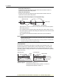
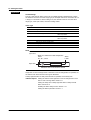
Pen Offset Compensation (Pen Model)
This function compensates for the pen offset (phase difference) along the time axis.
On 2-pen, 3-pen, and 4-pen recorders, there are offsets along the time axis (phase
difference) between the pens. This offset is corrected when pen offset compensation is
used.
Same time
Below is an explanation for the 2-pen model.
The recording of these two pens are offset by an amount of phase P. If pen offset
compensation is enabled, the measured values of pen 1 are stored in the memory, and
recorded when the chart paper is fed by an amount corresponding to P.
Reference pen (pen 2)
Pen 1
Recorder front panel
Chart paper
P
Chart feeding direction
By default, this function is disabled.
<Related Topics> Setting the pen offset compensation: Section 7.6
For the procedure to set the functions, see section 1.10, “Function Setup Guide.”
IM 04P01B01-01E
1-15
1.4 Recording
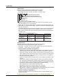
Printout
The figure below is used to explain the printout contents. The actual printout and font are
different from those illustrated in the figure. The printout positions are also slightly different.
Printout Example on the Pen Model
Manual printout
Nov.09.04 15:00
1
223.5mg/cm3
3 H 591.6˚C
2
4
437.2µS/cm
−0.222V
New chart speed printout
50mm/h*14:55
Periodic printout
Time tick cancel mark
Nov.09.04!
13:50*
Offset compensation mark
1
218.7mg/cm3
2
390.6µS/cm
3
H 598.4˚C
4
d −0.222V
0.0
1CH
Alarm
RED
Delta computation
50mm/h_
Scale
500.0
mg/cm3
Time tick
Recording color
Buffer overflow mark
Alarm printout
1H3*10:09
1H3 10:05
Message printout
09:52*START#205 ABCDEF
Recording start printout
08:00*25mm/h
Time tick
The time ticks are marks that indicate the positions of the date/time on the chart paper.
Time tick cancel mark
An exclamation point (!) is printed when the periodic printout time tick was not printed at the
correct position.
Channel number or tag printout
Channel numbers or tags can be printed.
<Related Topics>
Switching between channel number printout and tag printout: Section 7.7
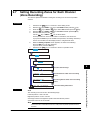
Setting the periodic printout (interval, reference time, types of measured values, and periodic
printout ON/OFF): Section 7.8
Turning printout ON/OFF (alarm printout, recording start printout, new chart speed printout, scale
printout for periodic printout, and recording color printout for periodic printout): Section 7.7
Setting the time format (alarm printout, message printout, recording start printout, and new chart
speed printout): Section 7.16
Turning periodic printout ON/OFF for each channel: Section 6.6
Executing manual print: Section 3.7
Setting the message string and printing messages: Sections 6.8 and 3.10
Clearing the alarm printout buffer: Section 3.9
Printing settings: Section 3.8
For the procedure to set the functions, see section 1.10, “Function Setup Guide.”
1-16
IM 04P01B01-01E
1.4 Recording
1
Printout Example on the Dot Model
Nov.09.04 16:00
1
223.5mg/cm3
3 H 591.6˚C
5
−0.665V
Functional Explanation and Setup Guide
Manual printout
2
437.2µS/cm
4
−0.222V
6 L −0.448V
New chart speed printout
_50mm/h*14:55
Periodic printout
Nov.09.04
Time tick
13:50
1
218.7mg/cm3
2
390.6µS/cm
3
H 598.4˚C
4
d −0.222V
5
−0.995V
6
L −0.448V
0.0
1CH
Delta computation
50mm/h_
Alarm
Scale
500.0
mg/cm3
Buffer overflow mark
Time tick
Alarm printout
1H3*10:09
1H3 10:05
Message printout
09:52*START#205 ABCDEF
Recording start printout
_08:00*25mm/h
Channel printout
Time tick
Channel Printout (Dot Model Only)
Prints the channel No. or tag by the trend recording. The channel No. or tag is printed
every approximately 25 mm on the chart paper. The channel printout can be enabled or
disabled. By default, the channel printout is enabled.
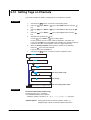
<Related Topics>
Switching between channel number printout and tag printout: Section 7.7
Setting the periodic printout (interval, reference time, types of measured values, and periodic
printout ON/OFF): Section 7.8
Turning printout ON/OFF (channel printout, alarm printout, recording start printout, new chart
speed printout, and scale printout for periodic printout): Section 7.7
Setting the time format (alarm printout, message printout, recording start printout, and new chart
speed printout): Section 7.16
Turning recording and printout ON/OFF for each channel (trend recording and periodic
printout): Section 6.6
Executing manual print: Section 3.7
Setting the message string and printing messages: Sections 6.8 and 3.10
Clearing the alarm printout buffer: Section 3.9
Printing settings: Section 3.8
For the procedure to set the functions, see section 1.10, “Function Setup Guide.”
IM 04P01B01-01E
1-17
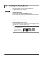
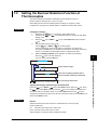
1.4 Recording
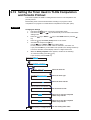
Alarm Printout
Alarm information is printed when an alarm occurs or releases.
Printout is not performed when the chart speed is as follows:
Pen model: 1600 mm/h or higher, dot model: 101 mm/h or higher
Time of alarm occurrence/release
Indicates that there are alarms that are not
printed because the alarm printout buffer is full.
Level number
Alarm type
Channel No. or tag
: Alarm occurrence,
: Alarm release
• The print condition can be set to (1) print when alarms occur and release, (2) print
only when alarms occur, or (3) do not print.
• Alarms that occur while an alarm printout is in progress are temporarily saved to the
buffer memory in a printout-wait condition. Alarms are cleared from the buffer memory
when they are printed.
• The number alarms that can be stored in the buffer is 8 and 12 on the pen model and
dot model, respectively. Alarms that occur while the buffer is full are not printed. A
buffer overflow mark is printed when there are alarms that cannot be printed because
the buffer is full.
• The time printout format can be selected.
Type
Hour:Minute
Printout format
10 : 00
Nov. 09
Month:Day:
Hour:Minute
10 : 00
Nov. 09. 2004
Year:Month:Day:
Hour:Minute:Second 10 : 00 : 00
Type
Hour:Minute:Second
Month:Day:
Hour:Minute:Second
Printout format
10 : 00 : 00
Nov. 09
00 : 00 : 00
* The format of year, month, and day varies depending on the setting (see the next page).
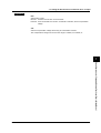
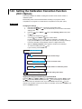
Periodic Printout
Measured values and other items are printed at the preset interval.
Printout is not performed when the chart speed is as follows:
Pen model: Less than or equal to 9 mm/h or greater than or equal to 1600 mm/h
Dot model: 9 mm/h or less, 101 mm/h or greater
• Printout Contents (for details, see appendix 1)
• Date/time, time ticks (marks that indicate the positions of the date/time on the chart
paper); measured values, alarm status, scale (leftmost and rightmost values of
span) and recording color (pen model) for each channel; and chart speed can be
printed. When pen offset is being executed on the pen model, the pen offset marks
are printed. On the pen model, if a time tick is not printed at the correct position, a
time tick cancel mark (!) is printed.
• Printout of measured values and alarm status can be enabled or disabled for each
channel.
• Printout of the scale and recording colors (pen model) can be enabled or disabled.
The scale can be printed when the recording zone is greater than or equal to 40 mm.
• The measured values for each channel can be selected from the following data types.
Instantaneous value (measured value at the time of periodic printout)
AVE (average of the measured values over an interval)
MIN (minimum value of the measured values over an interval)
MAX (maximum value of the measured values over an interval)
MIX (minimum , maximum , and average value of the measured values over an interval)
SUM (summed value of the measured values over an interval)
• Interval (for details, see appendix 2)
The printout interval can be set by specifying the value or set automatically in sync
with the chart speed.
For the procedure to set the functions, see section 1.10, “Function Setup Guide.”
1-18
IM 04P01B01-01E
1.4 Recording
Manual Printout
Measured values and alarm status can be printed manually using the keys. When
manual printout is executed, trend recording stops and restarts when manual printout is
complete.
Message Printout
Printout is not performed when the chart speed is as follows:
Pen model: 1600 mm/h or higher, dot model: 101 mm/h or higher
Preset messages can be printed on the chart paper using the keys. Five messages,
each within 16 characters, can be registered in advance.
• If message printout is executed while another message is being printed, the most
recent message is temporarily stored to the buffer memory in a printout-wait condition.
Messages are cleared from the buffer memory when they are printed.
• The number of messages that can be stored in the buffer is 5. If message printout is
executed when the buffer is full, the message is not printed. A buffer overflow mark is
printed when there are messages that cannot be printed because the buffer is full.
• The time printout format can be selected.
New Chart Speed Printout
Printout is not performed when the chart speed is as follows:
Pen model: 1600 mm/h or higher, dot model: 101 mm/h or higher
• When the chart speed is changed, the time tick (dot model), the date/time of change,
and the new chart speed are printed. An asterisk (*) shows there are messages that
cannot be printed.
• The time printout format can be selected.
Recording Start Printout
Printout is not performed when the chart speed is as follows:
Pen model: 1600 mm/h or higher, dot model: 101 mm/h or higher
When recording is started, the time tick (dot model), the time, and the chart speed can
be printed. An asterisk (*) shows there are messages that cannot be printed.
• The recording start printout can be enabled or disabled. By default, the recording start
printout is disabled.
• The time printout format can be selected.
Printout/Display Format of the Date (Version 1.11 or Later)
The printout/display format of the date can be selected from the list below. The setting
applies to all dates printed and shown on the display. However, this does not apply to the
format of the date printout of the message printout that include the measured values (/
BT1 option).
Type
Printout/Display Format
Y/M/D
2005/08/31
M/D/Y
08/31/2005
D/M/Y
31/08/2005
D.M.Y
31.08.2005
M.D.Y
Aug.31.2005
<Related Topics> Setting the printout/display format of the date: Section 7.19
For the procedure to set the functions, see section 1.10, “Function Setup Guide.”
IM 04P01B01-01E
1-19
1
Functional Explanation and Setup Guide
• Turning ON/OFF the Periodic Printout
Periodic printout can be turn ON/OFF. By default, periodic printout is enabled with the
interval synchronized to the chart speed. Also, the measured values that are printed
are the instantaneous values.
1.4 Recording
Setting Printout
List or Setup List can be printed. When setting printout is executed, trend recording stops
and restarts when the printout is complete.
List printout contains Setting Mode settings such as the input range and alarm for each
channel.
Setup List contains Basic Setting Mode settings such as the alarm output relay operation
and printout method.
• Printout Example of List on the Pen Model
The printout examples may appear differently from the actual printout as a result of functional
improvements made on the recorder after this manual was written.
For the procedure to set the functions, see section 1.10, “Function Setup Guide.”
1-20
IM 04P01B01-01E
1.4 Recording
1
• Printout Example of List on the Dot Model
Functional Explanation and Setup Guide
The printout examples may appear differently from the actual printout as a result of functional
improvements made on the recorder after this manual was written.
For the procedure to set the functions, see section 1.10, “Function Setup Guide.”
IM 04P01B01-01E
1-21
1.4 Recording
Header Printout (/BT1 Option)
When recording is started, the Start printout is performed, and recording starts. During
trend recording, you can print out messages (up to 5) that include measured values.*
When recording is stopped, End printout is performed.
Operation
(Operation
instruction)
1. Chart paper feed
2. Start printout
3. Recording start
(Record start)
Message printout 1
including measured
values*
(Message printout 1)
Message printout 2
including measured
values*
(Message printout 2)
1. Recording stop
2. End printout
3. Chart paper feed
(Recording stop)
• Example Printout (Dot Model)
End printout
Comment
Batch name (batch number and lot number)
date/time, and chart speed
Message printout 2 including measured
values*
Message printout 1 including measured
values*
Start printout
Comment
Batch name (batch number and lot number)
date/time, and chart speed
* Computed values can also be included on models with the /M1 optioon.
The printout examples may appear differently from the actual printout as a result of functional
improvements.
Start Printout and End printout
You can set “Start printout” and “Start printout 2” for the printout when recording starts.
Also, you can set “End printout” and “End printout 2” for the printout when recording stops.
Printout/Operation
Description
Comment
Prints 32 characters x 5 lines or less.
Batch name
Notes
Can be displayed in the main display.
Batch number
Prints up to 26 characters.
Lot number
Prints a number from 4-digits or 6-digits.
You can automatically increment by 1
when recording stops.
The date format prints out according to the date
printout/display format.
Date and time cannot be turned
On/Off independently.
Date/time
Chart speed
Prints the current chart paper feed speed.
Chart paper feed
Feeds the chart paper 50 mm or less before Start printout.
Feeds the chart paper 50 mm or less after End printout.
Ejection of pen offset You can record the portion of the data that remains after
compensating data
recording stops. Also, when recording the remaining
portion of the data, you can change the chart speed to
450 mm/h (fixed).
Steps of 1 mm
Steps of 1 mm
When pen offset compensating is On
(pen model).
You can select whether to print out the batch name, date/time, and chart speed. By default, the printout is enabled.
For the procedure to set the functions, see section 1.10, “Function Setup Guide.”
1-22
IM 04P01B01-01E
1.4 Recording
Batch Comment Switching Signal Status
Level: 0 (Open)
Level: 1 (Closed)
Start printout
Start printout 2
End printout
End printout 2
Record start/Stop Signal Status
Upon start Edge (rising)
Upon stop Edge (falling)
Remote Control Signal
Record start/stop
signal
Start
Stop
Start
Start printout
End printout
Start printout
Stop
Batch comment
switching signal
Concluded
successfully
End printout 2
Concluded
unsuccessfully
Message Printout Including Measured Values*
Following the specified message format, the date/time, message strings of the standard
function (5 strings of up to 16 characters), and measured instantaneous values* are
printed out together.
• Up to 5 messages of 35 characters can be entered.
• Messages are printed out in the order in which they are set.
• The specified number of characters specified for standard function messages is used,
then if a subsequent character string has been set, it is used next. Also, it can only be
used once for the message format.
Message Example
06/30 10:10 Process-1
134.8°C
Measured value on CH1 (no units)
Character string set for message 1
of the standard function
Date/time
*
Computed values can also be included on models with the /M1 optioon.
<Related Topics> Setting the header printout: Sections 7.24 and 6.14
Assigning functions to the remote control input terminals: Section 7.18
Setting the message string: Section 6.8
Enabling the message format: Section 7.24
Setting the message format: section 6.15
For the procedure to set the functions, see section 1.10, “Function Setup Guide.”
IM 04P01B01-01E
1-23
1
Functional Explanation and Setup Guide
• Switching between Start Printout and Start printout 2, and between End printout
and End printout 2
With the remote control function (/R1 option), you can change the items that are
printed out.
For example, when a process ends successfully, End printout is performed and the lot
number is updated. If the process fails, you can have End printout 2 be carried out
and the lot number remain not updated.
Depending on the status of the “batch comment switching signal,” the following
switches occur when the “record start/stop signal” switches:
1.5
Display
Displayed Information
Main Display
The recorder is capable of displaying measured values, alarm information, and so on the
VFD (Vacuum Fluorescent Display). Using normal fonts, 17 characters × 2 lines can be
displayed. Using large fonts, 11 characters can be displayed.
Status display
Main display
RECORD KEY LOCK
MATH
CHART END
ALARM
1 2 3 4 5 6
Various display types are available. Also, different displays can be assigned to the top
and bottom sections of the main display. These display types can be registered to
screens 1 to 15 and switched during operation using the keys.
Status Display
A status display is available at the bottom of the main display. The indicators below turn
ON/OFF.
• RECORD
This indicator turns ON when recording is started and turns OFF when stopped.
• ALARM 1 2 3 4 5 6
The numbers correspond to measurement channel numbers. The indicator turns ON
when an alarm occurs and turns OFF when the alarm is released.
If the alarm indication is set to hold operation, the indicator blinks when an alarm
occurs. When alarm ACK operation is performed, the indicator turns ON or OFF.
• MATH
This indicator turns ON when computation on the computation function (/M1 option) is
started and turns OFF when stopped.
• KEYLOCK
This indicator turns ON when key lock is enabled and turns OFF when disabled.
• CHART END
This indicator turns ON when the remaining amount of chart paper falls to approximately
2 cm on models with the FAIL/chart end function and output function (/F1 option).
Display Types
The following display types are available.
• Displays that show measured values
Measured values can be displayed numerically or using bar graphs. The channels that
are displayed can be switched automatically at constant intervals.
The bar graph displays 0 to 100% using 101 points.
0%
101 dots
100%
• Displays that show alarms
• Displays that show the date/time and chart speed
• Displays that show the remote control input and alarm output relay statuses (/R1 and
/Ax options)
• Displays that show the status
• System display
• Batch name (/BT1 option)
Different display types can be assigned to the top and bottom sections of the main display.
For the procedure to set the functions, see section 1.10, “Function Setup Guide.”
1-24
IM 04P01B01-01E
1.5 Display
1
Functional Explanation and Setup Guide
Several display examples are shown below. For details on the display types, see
“Display Function Specifications” in section 12.4.
1 Channel Digital + 1 Bar Graph Display
Channel No.
Alarm status
Measured value
Unit
Bar graph
Scale
Alarm point mark
Flag Display
Flag (the number indicates the channel No.)
Scale
Alarm Status Display
Symbol indicating
an alarm
Computation
channel
Measurement channel
Channel on which an alarm is occurring
Channel on which an alarm is not occurring
Channel on which an alarm is not set
Date/Time and Chart Speed
The date format can be specified (see page 1-19).
Date
Aug.31.2005 12000
11:26:37
mm/h
Time
Chart speed
Status Display
Alarm status
Remaining amount of chart paper is less than approx. 2 cm (/F1 option)
<Related Topics> Assigning display types to screens: Chapter 8
Switching displays: Section 3.6
Setting the bar graph display mode: Section 7.9
Changing the date format: Section 7.19
Setting the display brightness: Section 6.11
Displaying measured values: Section 12.4.
For the procedure to set the functions, see section 1.10, “Function Setup Guide.”
IM 04P01B01-01E
1-25
1.6
Computation Function (/M1 Option)
Computation Function
Computing equations can be set up using measured values and other computed values
as variables in computation-dedicated channels, and the computation can be executed.
The computed result can be recorded. Computation is performed every scan interval.
Channels Dedicated to Computations
The computation-dedicated channels below can be used.
Model
Number of Channels
Channel Names
Pen model
8
0A, 0B, 0C, 0D, 0E, 0F, 0G, and 0J
Dot model
12
0A, 0B, 0C, 0D, 0E, 0F, 0G, 0J, 0K, 0M, 0N, and 0P
Types of Computations
In the table below, y represents the computed result. X and n represent the measured
value, a constant, etc.
Type
Syntax in the Equation
Description
Four arithmetic operation +, –, *, /
Determines addition, subtraction, multiplication, and division.
Power
**
Determines the power. y = Xn
Square root
SQR()
Determines the square root.
Absolute value
ABS()
Determines the absolute value.
Common logarithm
LOG()
Determines the common logarithm. y=log10x
Exponent
EXP()
Determines the exponent. y = ex
Relational computation
.LT., .LE., .GT., .GE.,
.EQ., .NE.
Determines <, ≤, >, or ≥ of two elements and outputs “0” or “1.”
Logical computation
AND, OR, XOR, NOT
Determines the AND (logical product), OR (logical sum),
XOR (exclusive logical sum) of two elements,
NOT (negation) of an element and outputs “0” or “1.”
TLOG computation
TLOG.SUM(), TLOG.
MAX(), TLOG.MIN(),
TLOG.AVE(),
TLOG.P-P(),
Determines the sum (SUM), the maximum (MAX),
the minimum (MIN), the average (AVE),
and the maximum – minimum (P-P) at specified time
intervals. There are three timers for setting the interval.
Data That Can Be Used in Equations
In TLOG computation, the measured values of measurement channels or computed
values of computation channels can only be used. For all other computations, all of the
data types below can be used.
• Measured Values on Measurement Channels
Specified by the channel No. For channels that have scaling enabled, the scaled
values are used in the computation.
• Computed Values on Computation Channels
Specified by the channel No.
• Constants (K01 to K30)
The values assigned to K01 to K30 can be used as constants.
Range of values (maximum significant digits is 5):
–9.9999E+29 to –1.0000E–30, 0, 1.0000E–30 to 9.9999E+29
For the procedure to set the functions, see section 1.10, “Function Setup Guide.”
1-26
IM 04P01B01-01E
1.6 Computation Function (/M1 Option)
<Related Topics> Setting the computing equation, constant, and unit: Sections 9.2 to 9.4
Setting the TLOG timer: Sections 9.6 and 9.12
Handing of the Unit in Computations
In computations, measured/computed values are handled as values without units. For
example, if the measured value of channel 01 is 20 mV and the measured value of
channel 02 is 20 V, the computed result of 01 + 02 is 40.
Recording Computation Channels
Trend Recording
Trend recording is possible by setting the recording span for each computation channel.
The recording span of computation channels can be set in the range of –9999999 to
99999999 excluding the decimal.
Zone recording and partial expanded recording are also possible.
Assignment of Computation Channels to the Pens (Pen Model)
Trend recording is possible by assigning computation channels to arbitrary pens. Only
display or printout is possible for measurement channels or computation channels that
are not assigned to a pen. Assignment of pens is possible only on models with the
computation function.
Pen
1
2
3
4
Channel 01 02 03 04 0A 0B 0C 0D 0E 0F 0G 0J
Measurement channels
Computation channels
<Related Topics> Changing the channel assignment of recording pens: Section 9.14
Changing the Channel Recording Color (Dot Model)
The recording colors of computation channels can be changed. The default recording
colors of channels are indicated below.
Recording color
Purple
Red
Green
Blue
Brown
Black
Computation channels
0A
0G
0B
0J
0C
0K
0D
0M
0E
0N
0F
0P
For the procedure to set the functions, see section 1.10, “Function Setup Guide.”
IM 04P01B01-01E
1-27
1
Functional Explanation and Setup Guide
• Communication Input Data (Pen model: C01 to C08, dot model: C01 to C12)
This data type is set using the communication interface (/C7 or /C3 option).
Range of values (maximum significant digits is 5):
–9.9999E+29 to –1.0000E–30, 0, 1.0000E–30 to 9.9999E+29
For the procedure of setting the communication input data, see the µR10000/
µR20000 Communication Interface User’s Manual (IM04P01B01-17E).
• Status of the Remote Control Input Terminal (D01 to D05, /R1 option)
The status of the remote control input signal (1 or 0) can be used in the computation.
Use D01 to D05 (the number following the letter D is the remote control input terminal
number) to specify the status in the equations.
1.6 Computation Function (/M1 Option)
• The Number of Channels Being Trend Recorded and the Fastest Recording
Interval
The fastest recording interval varies depending on the number of channels being
trend recorded. Only display or printout is possible on measurement channels or
computation channels that are not trend recorded.
Number of Channels Being Trend Recorded
Fastest Recording Interval
6 channels or less
7 to 12 channels
13 to 18 channels
10 s
15 s
20 s
<Related Topics> Changing the channel recording color: Section 9.13
Enabling/Disabling trend recording for each channel: Section 9.9
Printout
Various printouts can be executed in the same fashion as measurement channels.
The computed values of computation channels can be printed at constant intervals by
using the periodic printout timer or the two TLOG timers. The TLOG timers can be used
only on the computation channels. For the printout contents when printing using the
TLOG timer, see appendix 1.
<Related Topics> Setting the periodic printout: Sections 7.8, 9.6, and 9.15
Setting the printout using the TLOG timer: Sections 9.6 and 9.12
Alarms
Up to 4 alarms can be assigned to each computation channel.
• The alarm types are high limit alarm (H), low limit alarm (L), delay high limit alarm (T),
and delay low limit alarm (t).
• Hysteresis can be specified to the values for activating and releasing the alarm. The
hysteresis applies only to high limit alarm (H) and low limit alarm (L). The hysteresis
width can be set in the range of 0.0% (Off) to 1.0% of the recording span in 0.1 steps.
The setting applies to all high limit alarms and low limit alarms. By default, the
hysteresis width is set to 0% (Off).
<Related Topics> Setting alarms: Section 9.5
Setting the alarm delay function: Sections 7.15 and 9.11
Setting the alarm hysteresis: Section 7.1
Display
Computation channels can be displayed on the VFD as with the measurement channels.
<Related Topics> Setting the bar graph display mode: Section 9.16
Starting/Stopping Computation
Computation can be started or stopped using keys.
<Related Topics> Starting/Stopping computation: Section 9.1
For the procedure to set the functions, see section 1.10, “Function Setup Guide.”
1-28
IM 04P01B01-01E
1.7
FAIL Output
When a failure occurs in the CPU of the recorder, a relay contact signal (1 signal) is
output. The relay is energized when the CPU is normal and de-energizes when a CPU
failure occurs. Therefore, relay output is carried out also when the power is turned OFF
(including a power failure). This relay behavior cannot be changed.
• FAIL Relay Output
NO
C
NC
NO
Normal
C
NC
Failure
NO
C
NC
Power-OFF
NO: Normally Opened, C: Common, NC: Normally Closed
Chart End Output
When the remaining amount of chart paper falls to approximately 2 cm, recording is
stopped, and the relay contact signal (1 relay) is output. The relay is energized in this
case. This relay behavior cannot be changed.
NO
C
Normal
NC
NO
C
NC
Chart end
NO
C
NC
Power-OFF
NO: Normally Opened, C: Common, NC: Normally Closed
For the procedure to set the functions, see section 1.10, “Function Setup Guide.”
IM 04P01B01-01E
1-29
1
Functional Explanation and Setup Guide
FAIL/Chart End Detection and Output Function
(/F1 Option)
1.8
Remote Control Function (/R1 Option)
Specified operations can be carried out by applying remote signals (contact or open
collector signals) to the remote control input terminals.
There are five remote control input terminals. An action can be assigned to each
terminal.
µR10000 Recorder
Contact
Open collector
Assignable Functions
• Recording start/stop
• Remote input signal: Rising edge signifies start; falling edge signifies stop
• Starts/stops recording.
• Applying a rising edge signal when recording is already in progress produces no
effect. Applying a falling edge signal when recording is stopped produces no effect.
• Chart Speed Switch
• Remote input signal: Level
• The chart paper is fed at the secondary chart speed while a level signal is applied
to the terminal. The secondary chart speed is set in advance.
• Message 1 Printout to Message 5 Printout
• Remote input signal: Trigger
• Prints message 1 to 5 on the chart paper.
• Manual Printout
• Remote input signal: Trigger
• Executes a manual printout.
• Alarm ACK
• Remote input signal: Trigger
• Alarm ACK is executed on all alarms that are occurring. This is valid only when the
alarm indication or output relay operation is set to hold.
• Internal Clock Adjustment
• Remote input signal: Trigger
• The internal clock of the recorder is adjusted to the nearest hour depending on the
time when the remote signal is applied.
Time When Signal Is Input
Adjustment
00 min 00 s to 01 min 59 s
Truncates the minutes and seconds.
Example: 10 hours 01 min 50 s becomes 10 hours 00 min 00 s.
02 min 00 s to 57 min 59 s
The time is not changed.
58 min 00 s to 59 min 59 s
Rounds up the minutes and seconds.
Example: 10 hours 59 min 50 s becomes 11 hours 00 min 00 s.
For the procedure to set the functions, see section 1.10, “Function Setup Guide.”
1-30
IM 04P01B01-01E
1.8 Remote Control Function (/R1 Option)
• Computation Reset (/M1 Option)
• Remote input signal: Trigger
• The computed results of computation channels are reset. This is valid only while
the computation is stopped. For all other cases, applying the remote signal
produces no effect.
• Priority to Remote Recording (/BT1 Option)
• Remote input signal: Edge (rising/start or falling/stop)
• Starts/stops recording.
• When started with a remote signal (on a remote signal rise), stop per key operation
or communication is disabled.
• Switching Batch Comment (/BT1 Option)
• Remote input signal: Level
• Switches between Start printout and Start printout 2, and between End printout and
End printout 2 depending on the status of the batch comment switching signal
when recording is started/stopped remotely.
• When starting/stopping by key operation, performs Start printout and End printout.
Remote Signal (Edge, Trigger, and Level)
The above actions are carried out on the rising or falling edge of the remote signal
(edge), the ON signal lasting at least 250 ms (trigger), or the ON/OFF signal (level).
Rising/Falling edge
Rising
Trigger
Level
Falling
250 ms or more
250 ms or more
Operates at the
secondary chart speed
For contact inputs, the remote signal rises when the contact switches from open to
closed and falls when the contact switches from closed to open. For open collector
signals, the remote signal rises when the collector signal (voltage level of the remote
control terminal) goes from high to low and falls when the collector signal goes low to
high.
<Related Topics> Assigning functions to the remote control input terminals: Section 7.18
Setting the secondary chart speed: Section 6.9
For the procedure to set the functions, see section 1.10, “Function Setup Guide.”
IM 04P01B01-01E
1-31
1
Functional Explanation and Setup Guide
• Computation Start/Stop (/M1 Option)
• Remote input signal: Rising edge signifies start; falling edge signifies stop
• Starts/stops the computation.
• If the computation is started, applying a rising edge signal produces no effect. If the
computation is stopped, applying a falling edge signal produces no effect.
1.9
Other Functions
Key Lock
Key lock is a function that prohibits key operations. When key lock is enabled, pressing
keys produces no effect. To release the key lock, a password is entered.
Key Lock Items
Each of the following keys can be included or excluded from the key lock function.
CHARACTER
RCD
MENU
DISP
FUNC
ESC/?
SHIFT
1 MENU
FEED
CH UP
Keys that can be locked
In the case of the FUNC key, each function of the FUNC key can be included or
excluded from the key lock function.
FUNC key functions: Alarm ACK execution, computation start/stop, manual printout and
setting printout, message printout, printout buffer clear, resetting of
the periodic printout report data (the average, etc.), and pen
replacement (pen model), ribbon cassette replacement (dot model)
<Related Topics> Setting the key lock function: Section 7.10
Using the key lock function: Section 3.13
Customize Menu
The menu can be customized to display only the menus that you use (version 1.31 or
later).
• Display only the items that you use on the FUNC key menu.
• Display only the items that you use on the Setting mode menu.
• Lock Basic Setting mode (use a password to enter the mode).
The pen position adjustment (pen model) and dot printing position adjustment (dot
model) can be set so that they can be used without the password.
Hold down
MENU for 3 s
Displays only the
FUNC key menu
items to be used
Basic Setting mode
Setting mode
Operation mode
Displays only the
setup menu items
to be used
Hold down
+
for 3 s
Password
No password
Pen and dot
printing position
adjustment
<Related Topics> Selecting the FUNC key menu: Section 7.20
Selecting the Setting mode menu: Section 7.21
Enabling/Disabling the customized menu: Section 7.22
Language
The display and recording language can be set to English, Japanese, German, or
French.
• English:
Alphabet, numbers, and symbols
• Japanese: Alphabet, numbers, katakana, and symbols
• German: German alphabet, numbers, and symbols
• French:
French alphabet, numbers, and symbols
*
German and French are supported on version 1.21 or later.
<Related Topics> Changing the language: Section 7.14
For the procedure to set the functions, see section 1.10, “Function Setup Guide.”
1-32
IM 04P01B01-01E
1.9 Other Functions
1
DST
<Related Topics> Using the DST: Section 6.16
Temperature Unit
The temperature unit can be set to Celsius or Fahrenheit. The setting applies to all
channels.
<Related Topics> Changing the temperature unit: Section 7.25
For the procedure to set the functions, see section 1.10, “Function Setup Guide.”
IM 04P01B01-01E
1-33
Functional Explanation and Setup Guide
If the recorder is used in a region that has DST, time can be switched automatically
between DST and standard time by setting the date/time when switching from the
standard time to DST and the date/time when switching back from DST to standard time.
When switching from standard time to DST, the clock is set ahead by 1 hour. When
switching back from DST to standard time, the clock is set back by 1 hour.
1.10 Function Setup Guide
This section explains the settings necessary to use various functions of the recorder.
Read the section corresponding to the function you wish to use.
Note
This section contains all the settings related to each item. If the desired setting is the same as
the default value, you do not have to set it.
Item
Description
Reference
Section
Date/Time setting
Use Clock in Setting mode
5.5
DST
Sets the date/time for switching between DST and standard time using
Aux > DST in Setting mode.
6.16
Setting initialization
Use Initialize in Basic Setting mode to initialize the settings of Setting mode
and Basic Setting mode to their default values.
7.17
Measuring input functions
Item
Description
Reference
Section
Range and span of the TC, RTD, or DC voltage
Use Range in Setting mode.
5.1
1-5V
• Range, span, and scale
Use Range in Setting mode.
• Unit
Use Unit in setting mode to set the unit after scaling.
• Low-cut
Use Personalize > Add function > 1-5V low-cut in Basic Setting mode and
select Use or Not.
If Use is selected, turn On/Off Low-cut using Range in Setting mode.
If Not is selected, the Low-cut item does not appear in the Range setting.
5.1
• Range, span, and scale
Use Range in Setting mode.
• Unit
Use Unit in setting mode to set the unit after scaling.
5.1
Scaling
5.3
7.15
5.1
5.3
Square Root Computation • Range, span, and scale
Use Range in Setting mode.
• Unit
Use Unit in setting mode to set the unit after scaling.
• Low-cut
Use Personalize > Add function > SQRT low-cut in Basic Setting mode
and select Use or Not.
If Use is selected, set the Low-cut point using Range in Setting mode.
If Not is selected, the Low-cut item does not appear in the Range setting.
5.1
Unused channels
Use Range > Skip in Setting mode to disable the trend recording (dot model)
and periodic printout of the target channel.
5.1
Bias
Use Personalize > Add function > Bias in Basic Setting mode and select Use
or Not.
If Use is selected, set the bias value that is added to the input using Bias in
Setting mode. If Not is selected, the Bias item does not appear.
7.15
5.3
7.15
5.1
6.12
Burnout detection function (TC input and 1-5V input)
Use Burnout in Basic Setting mode to set the burnout detection function for
each channel.
7.3
RJC of TC input
Use RJC in Basic Setting mode to select whether to use the internal
RJC function or an external RJC function.
7.4
Filter (pen model)
Use Filter in Basic Setting mode and select Use or Not.
If Use is selected, set the filter time constant using Aux > Filter in Setting mode.
If Not is selected, the Aux > Filter item does not appear.
7.12
6.2
1-34
IM 04P01B01-01E
1.10 Function Setup Guide
Item
Description
Functional Explanation and Setup Guide
Moving average (dot model)
Use Moving_AVE in Basic Setting mode and select Use or Not.
If Use is selected, set the number of samples of moving average using Aux >
Moving_AVE in Setting mode.
If Not is selected, the Aux > Moving_AVE item does not appear.
1
Reference
Section
7.11
6.3
Integration time of the A/D converter
Use A/D in Basic Setting mode to set the integration time of the A/D converter.
7.2
Temperature Unit
Select the temperature unit using Temperature in Basic Setting mode.
7.25
Item
Description
Reference
Section
Alarms for each channel
Use Alarm in Setting mode.
5.2
Alarm functions
Delay high limit alarm/delay low limit alarm
• Alarm type
7.15
Use Personalize > Add function > Alarm delay in Basic Mode and select Use or Not.
If Use is selected, delay high limit alarm (T) and delay low limit alarm (t) become 5.2
selectable under Alarm > Type in Setting mode.
If Not is selected, alarm delay cannot be selected.
• Alarm delay time
6.10
Use Aux > Alm delay T in Setting mode to set the alarm delay time.
High limit on rate-of-change alarm/low limit on rate-of-change alarm
Use Alarm in Setting mode and set the channel to rate-of-change alarm.
5.2
Use Alarm > Increase in Basic Setting mode to set the interval of the high limit on 7.1
rate-of-change alarm; use Alarm > Decrease in Basic Setting mode to set the
interval of the low limit on rate-of-change alarm.
Use the alarm ACK operation
• Relay operation and display operation
7.1
Set Alarm > Behavior in Basic Setting mode to Hold and set Alarm > Indicator
to Hold.
• Executing the alarm ACK operation
3.12
Use Func > Alarm ACK in Operation mode to execute the release of the
alarm output.
Set a hysteresis on the alarm occurrence/release value of high limit alarm and low limit alarm
Use Alarm > Hysteresis in Basic Setting mode to set the hysteresis to be applied 7.1
to the high limit alarm and low limit alarm of measurement channels.
Likewise, use Alarm > M_Hysteresis to set the hysteresis to be applied to the high
limit alarm and low limit alarm of computation channels (/M1 option).
Change the alarm output relay operation
If Alarm > Act in Basic Setting mode set to De_energize, alarm output relay is
energized during normal operation and de-energized when an alarm occurs.
7.1
Diagnosis output
Use Alarm > Diagnosis in Basic Setting mode to set the function.
7.1
Item
Description
Reference
Section
Chart speed
Use Chart in Setting mode to set the chart speed.
5.4
Recording functions
Turn trend recording ON/OFF (dot model)
Use Aux > Print out in Setting mode to set whether to trend record on each
measurement channel.
6.6
Change the recording color of measurement channels (dot model).
Use Color in Basic Setting mode to set the recording color of measurement channels.7.5
Record by compensating for the pen offset along the time axis (pen model)
Use Aux > POC in Setting mode to turn On/Off offset compensation.
7.6
Record by setting recording zone
Use Aux > Zone in Setting mode to set the recording zone for each channel.
6.4
Partial expanded recording Use Partial in Basic Setting mode and select Use or Not.
If Use is selected, set the display mode using Aux > Partial in Setting mode.
If Not is selected, the Aux > Partial item does not appear.
IM 04P01B01-01E
7.13
6.5
1-35
1.10 Function Setup Guide
Item
Description
Reference
Section
Periodic printout
Mar.31.2004!
15:50*
1
1.000V
2
-1.000V
0.000
1
RED
50mm/h_
Channel number
or tag
Measured value
2.000
V
Scale
Recording color
• Type of measured values to be printed/disable periodic printout
Use Print1 in Basic Setting mode to set the type of measured values to be
printed.
You can select Inst, Report (statistical calculation value), or Off.
• If Report is selected, use Print2 in Basic Setting mode to select the report
data type.
• Printout interval
Use Print 1 in Basic Setting mode to set the periodic printout interval.
• Turn On/Off periodic printout for each channel
Use Aux > Print out in Setting mode to enable/disable the periodic printout on
each measurement channel.
• Scale printout and recording color printout (pen model)
Use Print > Scale in Basic Setting mode to turn scale printout On/Off.
Use Print > Pen color in Basic Setting mode to turn pen color printout On/Off
(pen model).
Tag printout
Tag display
7.8
7.8
6.6
7.7
• Select channel printout or tag printout
7.7
Use Print > CH/Tag in Basic Setting mode to select whether to use channel
numbers or tags in printouts.
• Set the tag
6.7
Use Aux > Tag in Setting mode to set the tag name.
In data display setup mode, select Screen No. > (the screen number) >
8.2
Tag_1CH digital display, Tag_2CH digital display, Tag_1CH digital + 1CH bargraph,
or Tag_1CH digital + 4CH bargraph.
Alarm occurrence/release printout
• Turn printout On/Off
Use Print > Alarm in Basic Setting mode to select whether to print the alarm
occurrence and release, print only the alarm occurrence, or not print.
• Time printout format
Use Personalize > Time print > Alarm in Basic Setting mode to set the time
printout format when printing alarm occurrence/release.
Recording Start Printout
7.8
• Turn printout On/Off
Use Print > Record On in Basic Setting mode to enable/disable the recording
start printout.
• Time printout format
Use Personalize > Time print > RCD On in Basic Setting mode to set the time
printout format.
7.7
7.16
7.7
7.16
New chart speed printout
• Turn printout On/Off
7.7
Use Print > Chart speed in Basic Setting mode to set whether to print the new
chart speed when the chart speed is changed.
• Time printout format
7.16
Use Personalize > Time print > C. Speed in Basic Setting mode to set the time
printout format.
Message printout
• Set the message string
6.8
Use Aux > Message to set the message string to be printed.
• Time printout format
7.16
Use Personalize > Time print > Message in Basic Setting mode to set the time
printout format.
• Execute the message printout
3.10
Use Func > Message in Operation mode to execute the message printout.
Date format
Use Date format > Type in Basic Setting mode to set the printout/display format
of the date.
1-36
7.19
IM 04P01B01-01E
1.10 Function Setup Guide
1
Display functions
Description
Reference
Section
Display brightness
Use Aux > Brightness > Display in Setting mode to set the display brightness.
6.11
Bar graph display mode
Use Bar graph in Basic Setting mode to set the bar graph display mode.
7.9
Display type
Assigns the display type on the data display setup Screen No.
Chapter 8
Date format
Same as the Date format in “Recording functions.”
7.19
Item
Description
Reference
Section
Key lock
• Target keys and password
Use Keylock in Basic Setting mode to set the keys to be key-locked and the
password.
• Enable the key lock
Use Func > Keylock in Operation mode to turn key lock ON/OFF.
7.10
• Selecting the FUNC key display menu
Use Select menu > Function in Basic Setting mode to select the menus to
be displayed.
• Selecting the displayed menu of Setting mode
Use Select menu > Set mode in Basic Setting mode to select the menus
to be displayed.
• Executing the customize menu
Use Cust. menu in Basic Setting mode to set whether to use the customized
menu. If Use is selected, only the menus set to ON in the menu selection
are displayed, and Basic Setting mode is locked.
If Not is selected, all menus are displayed, and the Basic Setting mode
lock is released.
7.20
Language
Use Language in Basic Setting mode to set the display and printout language.
7.14
Internal light brightness
Use Aux > Brightness > Light in Setting mode to set the internal light brightness. 6.11
Functional Explanation and Setup Guide
Item
Other functions
Customized menu
3.13
7.21
7.22
Computation function (/M1 option)
Item
Description
Reference
Section
Computing equation and recording span
Use Math > Formula in Setting mode to set the computing equation and
recording span for each channel.
9.2
TLOG computation
9.12
If TLOG computation is selected, use Math > Timer in Basic Setting mode to
set the timer operation
Use Math > TLOG > Timer No. in Setting mode to set the timer used on each
computation channel.
9.6
Unit
Use Math > Unit in Setting mode to set the unit for each channel.
9.3
Constants
Use Math > Constant in Setting mode to define constants to be used in the
computing equations.
9.4
Alarms
Use Math > Alarm in Setting mode to set the alarm for each channel.
• Delay high limit alarm/delay low limit alarm
• Alarm type
Use Personalize > Add function > Alarm delay in Basic Mode and select
Use or Not (common with measurement channels).
If Use is selected, delay high limit alarm and delay low limit alarm become
selectable under Math > Alarm > Type in Setting mode. If Not is selected,
alarm delay cannot be selected.
• Alarm delay time
Use Math > Aux > Alm delay T in Setting mode to set the alarm delay time.
9.5
7.15
9.11
Record by setting recording zone
Use Math > Aux > Zone in Setting mode to set the recording zone for each channel. 9.7
Partial expanded recording Use Partial in Basic Setting mode and select Use or Not.
7.13
If Use is selected, set the display mode using Math > Aux > Partial in Setting mode. 9.8
If Not is selected, the Math > Aux > Partial item does not appear.
IM 04P01B01-01E
1-37
1.10 Function Setup Guide
Item
Description
Reference
Section
Change the recording color (dot model)
Use Color in Basic Setting mode to set the recording color of each computation
channel.
Recording pen assignment (pen model)
Assigns measurement/computation channels to the recording pens.
9.13
9.14
Turn trend recording ON/OFF (dot model)
Use Math > Aux > Print out > Trend in Setting mode to set whether to trend
record each computation channel.
9.9
Periodic printout
Mar.31.2004!
15:50*
1
1.000V
A
-100.00UNIT
-200.00
A
RED
50mm/h_
Channel number
or tag
Computed value
200.00
UNIT
Scale
Recording color
• Type of computed values to be printed/disable periodic printout
Common with measurement channels.
• If Report is selected, use Math > Print2 in Basic Setting mode to select
the report data type.
• Printout interval
Set Math > TLOG > Timer No. in Setting mode to Periodic.
The interval is common with measurement channels.
• Turn On/Off periodic printout for each channel
Use Math > Aux > Print out > Periodic in Setting mode to enable/disable the
periodic printout for each computation channel.
• Scale printout and recording color printout (pen model)
Common with measurement channels.
7.8
9.15
7.8
9.9
7.7
Periodic printout using TLOG timer (dedicated to computation channels)
Mar.31.2004!
15:50*
TAG-00A
100.00UNITA
B
1.0
-200.00
TAG-00A
RED
TLOG1
Channel number
or tag
Computed value
200.00
UNITA
Scale
Recording color
Timer number
• Use Math > Timer (TLOG) in Basic Setting mode to set the printout interval.
• Use Math > Timer (TLOG) > Print in Basic Setting mode to turn the printout On.
• Use Math > Aux > Print out > Periodic in Setting mode to enable/disable the
periodic printout for each computation channel.
• Set Math > TLOG > Timer No. in Setting mode to set the timer used on each
computation channel.
• Scale printout and recording color (pen model)
Common with periodic printout.
9.12
9.12
9.9
9.6
7.7
Alarm occurrence/release printout
Common with measurement channels.
7.7
Tag
• Channel/tag selection
Common with measurement channels.
• Tag name
Use Math > Aux > Tag in Setting mode to set the tag name.
7.7
Use Math > Bar graph in Basic Setting mode to set the bar graph display mode.
9.16
Bar graph display mode
9.10
Procedure when computed results are in error
Use Math > Error data in Basic Setting mode to set the procedure taken when the 9.17
computed results are in error.
1-38
IM 04P01B01-01E
1.10 Function Setup Guide
1
Remote control function (/R1 option)
Description
Remote control function (/R1 option)
• Assign functions to the remote control input terminals
Use Remote in Basic Setting mode to set the function to be assigned to the
remote control input terminal.
• Secondary chart speed
If “chart speed switching” is assigned, use Aux > Chart 2 in Setting mode to
set the secondary chart speed.
• Switching between start printout and start printout 2 and between end printout
and end printout 2 (/BT1 option)
If BatchCMT switch is assigned
Use Batch > Dual comment in Basic Setting mode to enable or disable start
printout 2 and end printout 2.
If Use is selected, set Batch > Detail > Start2 and End2 in Setting mode.
If Not is selected, the Batch > Detail > Start2 and End2 items in Setting mode
do not appear.
Reference
Section
Functional Explanation and Setup Guide
Item
7.18
6.9
7.24
6.14
Calibration Correction (/CC1 Option)
Item
Description
Calibration correction function
Use Personalize > Add function > Calibration in Basic Setting mode and select
Use or Not.
If Use is selected,
• Use Calibration in Basic Setting mode to set the correction mode and the
number of calibration points.
• Use Calibration in Setting mode to set the measured value and correction
value for each channel.
If Not is selected, the Calibration item does not appear.
Reference
Section
7.15
7.23
6.13
Header Printout (/BT1 Option)
Item
Description
Setting start printout and end printout
Use Batch in Basic Setting mode to set whether to use the start printout and end
printout. If Use is selected, select a Lot No. from 4 digits, 6 digits, or OFF.
If Use is selected,
Use Batch > Batch No. in Setting mode to set the batch number.
Use Batch > Lot No. in Setting mode to set the lot number.
Use Batch > Detail > Start, End in Setting mode.
If Not is selected, the Batch > Lot No. item in Basic Setting mode and the Batch
item in Setting mode do not appear.
Switch between start printout and start printout 2 and between end printout and end printout 2 (/R1 option)
• Switch settings
Assign “BatchCMT switch” to the remote control input terminal.
Use Batch > Dual comment in Basic Setting mode to set whether to use start
printout 2 and end printout 2.
If Use is selected, set Batch > Detail > Start2 and End2 in Setting mode.
If Not is selected, the Batch > Detail > Start2 and End2 items in Setting mode
do not appear.
• Executing the switch
The switch occurs according to the status of the “BatchCMT switch” signal
when “Record On/Off” or “Priority R_RCD” signal assigned to the remote
control input terminal rises or falls.
Printout of messages including measured/computed values
• Setting message strings
Use Aux > Message in Setting mode to enter the message to print out.
• Setting the message format
Use Batch > MSG format in Basic Setting mode and select whether to use the
message format.
If Use is selected, use Batch > MSG format > Message No. in Setting mode to
set the message format.
If Not is selected, the Batch > MSG format item does not appear.
• Executing message printout
Use Func > Message in Operation mode to execute the message printout.
IM 04P01B01-01E
Reference
Section
7.24
6.14
7.18
7.24
6.14
1.4
6.8
7.24
6.15
3.10
1-39
Chapter 2 Before Using the Recorder
2.1
Handling Precautions
This section describes the precautions to be taken when using the recorder. Read this
section before use.
• Use care when cleaning the recorder, especially any plastic parts. When cleaning,
wipe using a dry soft cloth. Do not use chemicals such as benzene or thinner, since
these may cause discoloring and deformation.
• Keep electrically charged objects away from the recorder as this may cause
malfunction.
• Do not apply volatile chemicals to the door glass, display, panel keys, etc. Do not
allow rubber and vinyl products to remain in contact with the recorder for long periods
of time. This may damage the recorder.
• When not in use, make sure to turn OFF the power switch.
• If there are any symptoms of trouble such as strange odors or smoke coming from the
recorder, immediately turn OFF the power switch and the power supply source. Then,
contact your nearest YOKOGAWA dealer.
IM 04P01B01-01E
2-1
Before Using the Recorder
Handling Precautions
2
2.2
Installation
Installation Location
Install the recorder indoors in a location that meets the following conditions. See also the
normal operating conditions described in section 12.6, “General Specifications.”
• Instrument Panel
The recorder is designed for panel mounting. The portable type (/H5x option) is
designed to be used on the desktop.
• Well-Ventilated Location
To prevent overheating, install the recorder in a well-ventilated location.
For the panel cut dimensions when arranging multiple recorders, see section 12.7.
Follow the panel cut dimensions providing adequate space between instruments
when other instruments are arranged on the panel. We recommend that you secure at
least 50 mm of space from the left, right, top, and rear panels on the portable type (/
H5x option).
• Minimum Mechanical Vibrations
Choose an installation location with the minimum mechanical vibration.
Installing the recorder in a location with large mechanical vibration not only causes
adverse effects on the mechanism but also may hinder normal recording.
• Horizontal
Install the recorder horizontally (However, the recorder can be inclined up to 30
degrees backwards for panel mounting).
Note
•
•
Condensation may occur if the recorder is moved to another place where both the ambient
temperature and humidity are higher, or if the temperature changes rapidly. In addition,
measurement errors will result when using thermocouples. In this case, let the recorder adjust
to the new environment for at least one hour before using it.
The chart paper may be adversely affected by a rapid change in the ambient temperature and
humidity.
Do not install the instrument in the following places.
• Outdoors
• In direct sunlight or near heat sources
Install the recorder in a place with small temperature fluctuations near room
temperature (23°C). Placing the recorder in direct sunlight or near heat appliances
can cause adverse effects on the internal circuitry.
• Where an excessive amount of soot, steam, moisture, dust, or corrosive gases
are present
Soot, steam, moisture, dust, and corrosive gases will adversely affect the recorder.
Avoid such locations.
• Near Strong Magnetic Field Sources
Do not bring magnets or instruments that produce electromagnetic fields close to the
recorder. Operating the recorder in strong magnetic fields can cause errors in the
measurements.
2-2
IM 04P01B01-01E
2.2 Installation
Installation Procedure
Fix in place
Screw temporarily
Panel
Panel Case
Mounting bracket
Mounting bracket
Attachment screw
In contact
with each other
Front
Torque driver
(flat blade)
Attachment screw
(The figure shows the case when the mounting
brackets are used on the top and bottom of the case.)
CAUTION
Tightening the screws too much can deform the case or damage the bracket.
For the dimensional drawings and panel cut dimensions, see section 12.7.
IM 04P01B01-01E
2-3
2
Before Using the Recorder
The recorder should be mounted on a steel panel of thickness 2 mm to 26 mm.
1.
Insert the recorder from the front side of the panel.
2.
As shown in the figure below, mount the recorder to the panel using the
mounting brackets that come with the package.
• Use two brackets to support the top and bottom or the left and right sides of
the case. (Remove the seal that is covering the holes for the mounting
brackets beforehand.)
• The proper torque for tightening the mounting screws is 0.7 to 0.9 Nm.
• Mount the recorder to the panel according to the procedure below.
• First, attach the two mounting brackets and temporarily fasten the
attachment screws.
• Next, fix the recorder in place by tightening the attachment screws with the
appropriate torque. When the recorder is approximately perpendicular to
the panel as you fasten the screws, press the mounting bracket against the
case so that they are in contact with each other.
2.3
Input Signal Wiring
General Precautions to Be Taken While Wiring
WARNING
To prevent the possibility of electric shock when wiring, make sure that the
power supply source is turned OFF.
CAUTION
• The input terminals of this instrument are specific to this instrument. Do not
connect the input terminals of the µR1000, µR1800 or other models, as
malfunction may result.
• If a strong tension is applied to the cable wired to the recorder, the terminals of
the recorder and/or the cable can be damaged. In order to prevent tension from
being applied directly on the terminals, fasten all wiring cables to the rear of the
mounting panel.
• Do not apply a voltage exceeding the following value to the input terminals as
this may damage the recorder.
• Maximum input voltage
Voltage range less than or equal to 200 mVDC, TC, RTD, and DI: ±10 VDC
Ranges other than those listed above: ±60 VDC
• Maximum common-mode voltage
±60 VDC (under measurement category II conditions)
• The recorder is an INSTALLATION CATEGORY II product.
Precautions to Be Taken While Wiring
Take the following precautions when wring the input signal cables.
It is recommended that crimp-on lug with insulation sleeves (designed for 4-mm screws)
be used when connecting the input/output signal wires to the terminals. However, this
does not apply clamped terminals (/H2).
Crimp-on lug with insulation
sleeves (for 4 mm screws)
For clamped terminals (/H2), the following wire is recommended.
• Conductive cross-sectional area for single wire: 0.14 mm2 to 1.5 mm2, stranded wire:
0.14 mm2 to 1.0 mm2
• Length of the stripped section of the wire: Approx. 5 mm
Take measures to prevent noise from entering the measurement circuit.
• Move the measurement circuit away from the power cable (power circuit) and ground
circuit.
• It is desirable that the object being measured does not generate noise. However, if
this is unavoidable, isolate the measurement circuit from the object. Also, ground the
object being measured.
• Shielded wires should be used to minimize noise caused by electrostatic induction.
Connect the shield to the ground terminal of the recorder as necessary (make sure
you are not grounding at two points).
2-4
IM 04P01B01-01E
2.3 Input Signal Wiring
• To minimize noise caused by electromagnetic induction, twist the measurement circuit
wires at short, equal intervals.
• Make sure to earth ground the protective ground terminal through minimum resistance
(less than 100 Ω).
Connecting the input wires in parallel with other devices can cause signal
degradation, affecting all connected devices.
If you need to make a parallel connection, then
• Turn the burnout detection function OFF.
• Ground the instruments to the same point.
• Do not turn ON or OFF another instrument during operation. This can have adverse
effects on the other instruments.
• RTDs cannot be wired in parallel.
Arrangement of the Measuring Input Terminals
A terminal cover is screwed in place on the measuring input terminal block on the rear
panel. A label indicating the terminal arrangement is affixed to the cover.
Measuring input terminal block
Terminal cover
attachment screws
Pen Model
b
–/B
+/A
Channel 1
Channel 2
Channel 3
Channel 4
Screw input terminal
IM 04P01B01-01E
+/A
Channel 2 –/B
b
+/A
–/B
b
Channel 1
Channel 3
Channel 4
Clamped input terminal
(/H2 option)
2-5
2
Before Using the Recorder
When using internal reference junction compensation on the thermocouple input,
take measures to stabilize the temperature at the input terminal.
• Always use the terminal cover.
• Do not use thick wires which may cause large heat dissipation (cross sectional area of
0.5 mm2 or less recommended).
• Make sure that the ambient temperature remains reasonably stable. Large
temperature fluctuations can occur if a nearby fan turns ON or OFF.
2.3 Input Signal Wiring
Dot Model
b
–/B
+/A
Channel 1
Channel 2
Channel 3
Channel 4
Channel 5
Channel 6
+A
b
Channel 1
Channel 4
Channel 3
Channel 6
Channel 5
Screw input terminal
1.
2.
+/A
–/B
b
Channel 2 –/B
Clamped input terminal
(/H2 option)
Turn OFF the recorder and remove the terminal cover.
Connect the signal wires to the terminals.
Screw input terminal
Clamped input terminal
Signal wire
Crimp-on lug with
insulation sleeves
Signal wire
Flat-blade
screwdriver
Philips
screwdriver
Note
Input signal wires of diameter less than or equal to 0.3 mm may not be secured firmly for
clamped terminals (/H2). Fold over the conducting section of the wire, for example, to make
sure that the wire is securely connected to the clamped terminal.
3.
2-6
Replace the terminal cover and fasten it with screws.
The proper torque for tightening the screws is 0.6 N-m.
IM 04P01B01-01E
2.3 Input Signal Wiring
Measuring Input Wiring
Thermocouple input
b
Resistance temperature detector input
–/B +/A
b
–/B +/A
2
Before Using the Recorder
Leadwire resistance:
10 Ω max./wire. The resistance
of the three wires should be
equal.
Extension leadwire
b
B
A
DC voltage input, 1-5V input,
and ON/OFF input
b –/B +/A
DC current input
b
–/B +/A
Shunt resistor
+
–
DC voltage
1-5V
ON/OFF
Example: For a 4 to 20 mA
input, a shunt resistor of
250 Ω ± 0.1% can be used to
convert to 1-5V input.
+
–
DC current
Note
RTD input terminals A and B on the dot model are isolated on each channel. Terminal b is
shorted internally across all channels. However, for 3 legs isolated RTDs (/N2 option), input b
is also isolated for each channel.
IM 04P01B01-01E
2-7
2.4
Optional Terminal Wiring
General Precautions to be Taken While Wiring the Input/Output Signal Wires
WARNING
• To prevent electric shock while wiring, ensure that the power supply source is
turned OFF.
• If a voltage of more than 30 VAC or 60 VDC is to be applied to the output
terminals, use ring-tongue crimp-on lugs with insulation sleeves on all terminals
to prevent the wires from slipping out when the screws become loose.
Furthermore, use double-insulated wires (dielectric strength of 2300 VAC or
more) for the signal wires on which a voltage of more than 30 VAC or 60 VDC is
to be applied. For all other wires, use basic insulated wires (dielectric strength of
1390 VAC). To prevent electric shock, attach the terminal cover after wiring and
make sure not to touch the terminals.
Crimp-on lug with insulation sleeves
(for 4 mm screws)
CAUTION
• The option terminals of this instrument are specific to this instrument. Do not
connect the option terminals of the µR1000, µR1800 or other models, as
malfunction may result.
• To prevent fire, use signal wires having a temperature rating of 70°C or more.
• If a strong tension is applied to the cable wired to the recorder, the terminals of
the recorder and/or the cable can be damaged. In order to prevent tension from
being applied directly on the terminals, fasten all wiring cables to the rear of the
mounting panel.
Arrangement of the Optional Terminals
As shown in the figure below, the optional terminal block is located on the rear panel.
The optional terminal block is provided on the recorder when an option that requires
input/output is installed such as the alarm output relay (/A1, /A2, or /A3 option), FAIL/
chart end output (/F1 option), and remote control function (/R1 option). A terminal cover
is screwed in place on the optional terminal block. A label indicating the terminal
arrangement is affixed to the terminal block.
Optional terminal block
Terminal cover
attachment screws
2-8
IM 04P01B01-01E
2.4 Optional Terminal Wiring
/A1
/A1/F1
/A1/R1
/A1/F1/R1
NO
C
NC I01
NO
C
NC I01
NO
C
NC I01
NO
C
NC I01
NO
C
NC I02
NO
C
NC I02
NO
C
NC I02
NO
C
NC I02
NO
C
NC CE
NO
C
NC CE
NO
C
NC FAIL
NO
C
1
2
NC FAIL
3
4
5
2
/A2/F1
1
2
3
4
5
C
(/R1)
/A2/R1
C
(/F1)
(/R1)
/A2/F1/R1
NO
C
NC I01
NO
C
NC I01
NO
C
NC I01
NO
C
NC I01
NO
C
NC I02
NO
C
NC I02
NO
C
NC I02
NO
C
NC I02
NO
C
NC I03
NO
C
NC I03
NO
C
NC I03
NO
C
NC I03
NO
C
NC I04
NO
C
NC I04
NO
C
NC I04
NO
C
NC I04
NO
C
NC CE
NO
C
NC CE
NO
C
NC FAIL
NO
C
1
2
NC FAIL
3
4
5
/A3
(/F1)
/A3/R1
1
2
3
4
5
C
C
(/F1)
(/R1)
/R1
C
NC I01
NO
C
NC I01
NO
C
NC I02
NO
C
NC I02
NO
C
NC I03
NO
C
NC I03
NO
C
NC I04
NO
C
NC I04
NO
C
NC I05
NO
C
NC I05
NO
C
NO
C
NC I06
NO
C
NO
C
1
2
NC I06
3
4
5
/F1/R1
(/R1)
/F1
NO
C
Before Using the Recorder
/A2
(/F1)
NC CE
(/F1)
NC FAIL
(/R1)
1
2
3
4
5
C
(/R1)
CE: Chart end
NC CE
(/F1)
NC FAIL
NO
C
NO
C
1
2
3
4
5
C
(/R1)
Alarm Output Relay Terminals and FAIL/Chart End Output Relay Terminals
NC (Normally Closed), C (Common), NO (Normally Opened)
Remote Control Input Terminals
1 to 5 (remote control input terminals), C (Common)
Alarm output terminals correspond to I01 to I06 in the alarm output relay settings.
Remote control input terminals 1 to 5 correspond to numbers 1 to 5 in the remote control
input settings.
IM 04P01B01-01E
2-9
2.4 Optional Terminal Wiring
Wiring Procedure
1.
2.
Turn OFF the recorder and remove the terminal cover.
Connect the input signal wires to the terminals.
Philips
screwdriver
Crimp-on lug with
insulation sleeves
3.
Replace the terminal cover and fasten it with screws.
The proper torque for tightening the screws is 0.6 N-m.
Alarm output
FAIL/chart end output
Relay contact output
NO
Remote control input
Relay contact input
(Voltage-free contact)
1
2
3
Transistor input
(Open collector)
1
2
3
C NC
4
5
C
4
5
C
Note
To reduce noise, use a shielded cable for the wiring of the remote control input terminals.
Connect the shield to the ground terminal of the recorder.
• Relay Contact Output Specifications
Output type:
Relay
Contact rating:
250 VAC (50/60 Hz)/3 A, 250 VDC/0.1 A (resistive load)
Dielectric strength:
1500 VAC at 50/60 Hz for one minute (between output
terminals and the ground terminal)
• Relay Contact Input/Transistor Input Specifications
Input signal:
• Voltage-free contact: Contact closed at 200 Ω or less and
contact open at 100 kΩ or greater
• Open collector: 0.5 V or less (30 mADC) when turned ON,
leakage current of 0.25 mA or less when turned OFF
Input format:
Photocoupler isolation (shared common)
Dielectric strength:
500 VDC for one minute between input terminals and the
ground terminal
2-10
IM 04P01B01-01E
2.5
Power Supply Wiring
Precautions to Be Taken While Wiring the Power Supply
2
WARNING
Panel Mount Type
• To prevent electric shock when wiring, ensure the main power supply is turned OFF.
• To prevent the possibility of fire, use 600 V PVC insulated wire (AWG 20 to 16)
or an equivalent wire for power wiring.
• Make sure to earth ground the protective earth terminal through a grounding
resistance less than 100 Ω before turning ON the power.
• Use crimp-on lugs (designed for 4 mm screws) for power and ground wiring
termination.
• To prevent electric shock, make sure to close the transparent cover for the
power supply wires.
• Make sure to provide a power switch (double-pole type) on the power supply
line in order to separate the recorder from the main power supply. Put an
indication on this switch as the breaker on the power supply line for the recorder
and indications of ON and OFF.
Switch specifications
Rated power current: 1 A or more (other than /P1), 3 A or more (/P1 option)
Rated rush current: 60 A or more (other than /P1), 70 A or more (/P1 option)
Complies with IEC 60947-1, 3.
• Connect a fuse in the power supply line. Use a fuse approved by CSA (for the
use in North America) or VDE (for the use in Europe).
2 A to 15 A (other than /P1), 4 A to 15 A (/P1 option)
• Do not add a switch or fuse to the ground line.
Portable Type (/H5x Option)
• Ensure that the source voltage matches the rated power supply voltage of the
instrument before connecting the power cord.
• Connect the power cord after checking that the power switch of the portable
type is turned OFF.
• To prevent electric shock or fire, be sure to use the power cord for the portable
type supplied by YOKOGAWA.
• Make sure to connect protective earth grounding to prevent electric shock.
Connect the power cord of the portable type to a three-prong power outlet
equipped with a protective earth terminal.
• Do not use an extension cord that does not have a protective grounding wire.
The protective features of the instrument will be rendered ineffective.
Use a power supply that meets the following conditions:
Item
Power Supply Specifications
(Options Other Than /P1) (/P1 Option)
Rated supply voltage
100 to 240 VAC
24V DC/AC
Allowable power supply voltage range
90 to 132/180 to 264 VAC
21.6 V to 26.4 VDC/AC
Rated power supply frequency
50/60 Hz
50/60 Hz (for AC)
Allowable power supply frequency range
50/60 Hz ± 2%
50/60 Hz ± 2% (for AC)
Maximum power consumption
40 VA
25 VA (for DC) or 35 VA (for AC)
Note
Do not use a supply voltage in the range 132 to 180 VAC, as this may have adverse effects
on the measurement accuracy.
IM 04P01B01-01E
2-11
Before Using the Recorder
Make sure to follow the warnings below when wiring the power supply. To prevent
electric shock and damage to the recorder, observe the following warnings.
2.5 Power Supply Wiring
Wiring Procedure
Panel Mount Type
The power supply terminals and protective ground terminals are located on the rear
panel.
1.
Turn OFF the power switch on the recorder and open the power terminal cover.
Screw for fixing
the power terminal
cover in place
Power
terminal block
Power
terminal cover
Open
2.
Wire the power cord and the protective ground cord to the power supply
terminals.
Use ring-tongue crimp-on lugs (designed for 4 mm screws).
Crimp-on lug
with insulation
sleeves
Power cord
• Other than /P1 • /P1
(24 VDC/AC power supply)
L
L
+
N
N
DC/AC24V
Philips
screwdriver
3.
Protective ground
cord
Close the power supply terminal cover and secure it with the screw. The proper
torque for tightening the screws is 0.6 N-m.
Portable Type (/H5x Option)
1.
Check that the power switch to the recorder is turned OFF.
2.
Connect the plug on the accessory power cord to the power supply connector
on the rear panel.
10
50 040 /60H240V
VA
MA z ~
X
3.
2-12
Ensure that the power outlet to be used meets the conditions on the previous
page and that the voltage of the power supply is within the maximum voltage
rating of the power cord, then connect the other end of the power cord to the
power supply outlet.
The AC outlet must be of a three-prong type with a protective earth ground
terminal.
IM 04P01B01-01E
2.6
Turning ON/OFF the Power Switch
2
CAUTION
The power switch is located inside the door at the lower right.
The power switch is a push button. Press once to turn it ON and press again to turn it
OFF.
When the power switch is turned ON, a self-diagnosis program runs for a few seconds,
and the recorder is ready for operation.
Note
•
•
•
•
If the input wires are connected in parallel with other devices, do not turn ON/OFF the power
switch of the recorder or another device during operation. This can have adverse effects on
the measured values.
If nothing is displayed when the power switch is turned ON, turn OFF the power switch and
check the points listed above one more time. After checking the points, turn ON the power
switch again. If the unit still does not work, it is probably malfunctioning. Contact your nearest
YOKOGAWA dealer for repairs.
If an error message is displayed on the screen, take measures according to the description in
chapter 10, “Troubleshooting.”
Turn ON the power switch, let the recorder warm up for at least 30 minutes, and then start the
measurements.
Checking the Date/Time
The date/time is shown on the display when the DISP key is pressed several times. To
correct the date/time, see the reference indicated below.
<Related Topics> Setting the date/time: See section 5.5
IM 04P01B01-01E
2-13
Before Using the Recorder
Check the following points before turning ON the power switch.
• The power cord/wires are connected correctly to the recorder.
• The recorder is connected to the correct power supply (see section 2.5).
Chapter 3 Names of Parts and Run Operations
3.1
Names of Parts
Front
Name plate
The model name is written
on the name plate.
3
Door
Tag plate
Used to write
channel names.
Chart cassette
Holds the chart paper.
Pen model
Mounting hole
There is one hole on each of the
top, bottom, left, and right panels.
The hole is covered with a seal.
Power switch
Turns ON/OFF the power each
time the switch is pressed.
Dot model
Recording pen
Records the measured value.
Plotter pen
Prints various types
of information.
Ink ribbon
Six-color ink.
Printer carriage
Records measured values
and prints various types of
information.
Display and key panel (see the next page)
There is an internal light on the bottom section
of the display and key panel. It lights up the
recording area of the chart paper.
IM 04P01B01-01E
3-1
Names of Parts and Run Operations
Display and key panel
Hold the tab at the lower
left and pull to open.
3.1 Names of Parts
Display and Key Panel
Status display
Displays the following information.
RECORD
Illuminates while recording measured values.
KEY LOCK
Illuminates when key lock is enabled.
MATH
Illuminates when computation on the computation function (/M1 option)
is in progress.
CHART END
Illuminates when the chart paper is out (/F1 option).
ALARM 1 to 6 Illuminates when an alarm is occurring on channels 1 to 6.
Main display
Displays the measured values. Also, displays the setup screen when
setting functions.
RECORD KEY LOCK
CHARACTER
RCD
MENU
MATH
DISP
CHART END
FUNC
1 2 3 4 5 6
ALARM
ESC/?
SHIFT
1 MENU
FEED
CH UP
Seven keys are available.
For all keys except RCD, functions marked above the keys are enabled when
setting functions or when the FUNC key or the DISP MENU key is pressed.
<While setting functions, when the FUNC key/DISP MENU key is pressed>
CHARACTER Key: Changes the character type when entering a character. Press
this key while holding down the SHIFT key to switch the character type in reverse
order.
UP/DOWN Key: Switches the setup item or the value.
Press this key while holding down the SHIFT key to switch the setup item
or the value in reverse order.
LEFT/RIGHT Key: Moves the cursor to the right when entering a value
or character. Press this key while holding down the SHIFT key to move
the cursor to the left..
ESC Key: Cancels the operation.
When pressed with the SHIFT key, the display of the comment
on the setting turns ON/OFF.
SHIFT Key: Used with the
CHARACTER key.
key,
key, or the
ENTER Key: Confirms the setup item or value.
CHARACTER
RCD
MENU
DISP
FUNC
ESC/?
SHIFT
1 MENU
FEED
CH UP
<During normal operation>
CH UP key
Switches the displayed channel.
(when manual switching is specified)
FEED key
Feeds the chart paper.
DISP MENU key
Hold this key down for 3 seconds to switch to the data display
setup screen. Hold this key down for 3 seconds also to exit
from the data display setup screen.
FUNC key
Used when executing manual printout, message printout, etc.
DISP key
Switches the screen in the main display.
MENU key
Hold this key down for 3 seconds to enter Setting mode. Hold this key down for
3 seconds also to exit from Setting mode.
RCD key
Starts/stops recording.
Note
This manual denotes the operation of pressing a key while holding down the SHIFT key as
SHIFT + the other key (for example: SHIFT +
key).
3-2
IM 04P01B01-01E
3.1 Names of Parts
Rear Panel
Heatsink
Dissipates the internal heat.
Power terminal block
The power terminal and protective ground terminal.
Optional terminal block
This is where terminals or ports used by options such
as alarm output relays and communication interface
are installed.
3
Names of Parts and Run Operations
Measuring input terminal block
Measuring input terminals
Ethernet port (/C7 option)
Portable Type (/H5x Option)
Carrying handle
10
50 040 /60H240V
VA
MA z ~
X
Protective ground terminal (spare)
Power terminal
With protective ground terminal
(attach the specified power cord)
Feet (4 pieces)
IM 04P01B01-01E
3-3
3.2
Installing or Replacing the Chart Paper
CAUTION
• Do not install or remove the chart cassette with the chart paper guide open. This
may damage the stopper.
• Continuing to record or print without the chart paper on the dot model can cause
damage to the chart cassette platen (the cylindrical section that holds the paper
during the recording operation). Be sure to replace the chart paper ahead of
time.
Loading the Chart Paper
1.
2.
Open the door.
If recording is in progress, press the
RCD
key to stop the recording.
Remove the chart cassette.
Gently pressing the left and right stoppers inward. The bottom section of the
chart cassette comes out. Gently lift the chart cassette and pull it out from the
recorder case.
Stopper
3-4
IM 04P01B01-01E
3.2 Installing or Replacing the Chart Paper
3.
Open the chart holder and the chart paper guide.
Chart holder
This sheet is provided on models
with the chart end detection
function (/F1 option).
Do not remove or bend this sheet.
3
4.
Load the chart paper.
Riffle the chart thoroughly before loading.
Make sure that the sprocket teeth of the chart drives are properly engaged in the
chart paper perforations. Make sure not to load the chart paper backwards.
Z-fold chart paper
Sprocket teeth
5.
Close the chart holder and close the chart paper guide.
Chart holder
Chart paper guide
IM 04P01B01-01E
The side with the
long rectangular
holes is the right side.
3-5
Names of Parts and Run Operations
Chart paper guide
3.2 Installing or Replacing the Chart Paper
6.
Replace the chart cassette back into the recorder case.
Align the left and right projections of the sprocket section with the guide grooves
of the recorder and press the entire chart cassette into the recorder case. The
chart cassette is fixed in place with the stoppers.
Stopper
Feeding the Chart Paper
7.
Press the FEED key to assure that the chart moves two or more folds smoothly
into the chart receiver.
If it moves unsteadily, do the installing procedure again.
3-6
IM 04P01B01-01E
3.3
Installing/Replacing Felt Pens or Plotter Pen
(Pen Model)
CAUTION
• Do not press or pinch the felt tip to prevent deformation.
• Do not move the penholder left or right by force to protect the driving
mechanism.
• Make sure to remove the pen cap before installation.
• Use pen caps of the same ink color. If a pen cap of a different ink color is used
on the pen, the remaining ink in the cap may be absorbed through the pen tip,
and the ink may change its color.
3
1.
2.
3.
4.
Open the door.
If recording is in progress, press the RCD key to stop the recording.
Open the display and key panel section.
You can open the display and key panel section by holding the tab at the lower
left and pulling it toward you.
Hold the felt pen cartridge and pull it out from the pen holder.
If the pen (pen holder) is at a position that is not easily accessible, see “When
the Pen (Pen Holder) Is at a Position That Is Not Easily Accessible” on the next
page.
Remove the cap from the new felt pen and insert the pen firmly into the pen
holder.
From the top: pen 1 (red),
pen 2 (green), pen 3 (blue),
and pen 4 (violet).
Display and key panel
IM 04P01B01-01E
3-7
Names of Parts and Run Operations
Replacing Felt Pens
3.3 Installing/Replacing Felt Pens or Plotter Pen (Pen Model)
When the Pen (Pen Holder) Is at a Position That Is Not Easily Accessible
If the pen (pen holder) is at a position that is not easily accessible, carry out the
procedure below to move it near the center position.
1.
Turn ON the power switch and press the FUNC key.
( DISP ) key several times to display the Pen exchange screen.
2.
Press the
Func=Pen
3.
exchange
Press the
( CH UP ) key.
The pen (pen holder) moves near the center position, and the Pen exchange
= End appears.
Note
When the pen moves, a line is drawn on the chart paper.
4.
5.
Replace the pen.
Press the
( CH UP ) key.
The screen returns to the data display screen.
Replacing the Plotter Pen
1.
2.
3.
4.
3-8
Open the door.
If recording is in progress, press the RCD key to stop the recording.
Open the display and key panel section.
Hold the plotter pen cartridge and pull it out from the pen holder.
Remove the cap from the new plotter pen and insert the pen firmly into the pen
holder.
IM 04P01B01-01E
3.4
Installing/Replacing the Ribbon Cassette (Dot
Model)
CAUTION
• Improper cassette insertion may cause the color to change or damage the ribbon.
• Do not apply upward force to the printer carriage. If you do, the carriage position
may be offset, and the recorder may not print correctly.
2.
3.
Open the door.
If recording is in progress, press the RCD key to stop the recording.
Press the FUNC key.
( DISP ) key several times to display R. exchange.
Press the
Func=R.
4.
5.
exchange
Press the
( CH UP ) key.
The printer carriage moves near the center position, and R. exchange = End is
displayed.
Open the display and key panel section.
You can open the display and key panel section by holding the tab at the lower
left and pulling it toward you.
Note
• Moving of the printer carriage using keys is a function available on version 1.11
or later.
• If the recorder is OFF, pinch the printer carriage and move it near the center
position.
Printer carriage
IM 04P01B01-01E
3-9
Names of Parts and Run Operations
1.
3
3.4 Installing/Replacing the Ribbon Cassette (Dot Model)
6.
Remove the ribbon cassette.
Pull the left-hand part of the ribbon cassette so that the cassette holder tab
disengages, and pull the ribbon cassette out from the recorder case.
Holder tab
7.
Install a new ribbon cassette.
First, insert the right-hand part and then the left-hand part into the cassette holder.
Check that the cassette is properly engaged with the cassette holder tab.
If inserting the ribbon cassette is difficult, turn the ribbon feeding knob in the
direction of the arrow to align the ribbon feeding shaft of the cassette with the
ribbon feeding shaft hole of the holder.
Cassette holder
Holder tab
Hole for the ribbon
feed shaft
Ribbon feeding knob
8.
9.
3-10
Turn the ribbon feeding knob in the direction of the arrow a half turn or more to
check that the ribbon is feeding properly. If the ribbon is loose, turn the knob in
the direction of the arrow to tighten it.
Return the display and key panel section to its original position, and press the
( CH UP ) key.
The screen returns to the data display screen.
IM 04P01B01-01E
3.5
Starting/Stopping the Recording
This section describes the procedures for starting/stopping the recording and checking
the recorded result.
Procedure
3
Stopping the Recording
While recording is in progress, press the RCD key to stop recording.
The word “RECORD” on the status display clears.
Feeding the Chart Paper
The chart paper is fed while the
FEED
key is held down.
Viewing the Recorded Results
Pull the front cover tab of the chart cassette to open the front cover. The recorded chart
paper can be pulled out for viewing.
Recorded chart paper can
be pulled out.
Front cover tab
<Related Topics> Changing the chart speed: Section 5.4
IM 04P01B01-01E
3-11
Names of Parts and Run Operations
Starting the Recording
Press the RCD key to start recording.
The status display shows the word “RECORD.”
3.6
Switching the Display Screen
This section describes the procedure for switching the display screen.
To change the displayed content, see chapter 8.
Procedure
Switching the Display Screen
The display screen switches each time the DISP key is pressed.
Screen 01 through 15 are switched in order. Screens that are set to “Skip” are skipped.
Channel Auto Switching
On screens that show the measured values and computed values, the displayed channel
is automatically switched in ascending order. The switching interval can be set to 1 s, 2
s, 3 s, 4 s, or 5 s.
Measurement channels set to Skip and computation channels set to OFF are not
displayed.
Switching the Displayed Channel Using Keys
If Manual switching is specified, the channel switches each time the
in ascending order. All channels are displayed in order.
CH UP
key is pressed
Note
The operation is different between auto channel switching and manual switching using keys
on the 2-channel digital display.
3-12
During auto switching
01
02
03
04
05
06
When switching using keys
01
02
02
03
03
04
IM 04P01B01-01E
3.7
Printing Measured Values (Manual Printout)
The measured values of all channels are printed.
Procedure
Starting the Manual Printout
1.
Press the FUNC key.
2.
Press the
key to select Print out and then press the
3.
out
Press the
key with ManualStart shown on the screen.
Manual printout starts. The screen returns to the data display screen.
Print=ManualStart
Note
•
•
•
When manual printout is executed, trend recording is suspended. However, the recorder
continues the measurement and alarm detection (in the background).
When manual printout is complete, trend recording resumes.
If an alarm occurs during the manual printout, the alarm is printed after the trend recording
resumes.
Aborting the Manual Printout
The following procedure is for aborting the manual printout that is in progress.
1.
Press the FUNC key.
2.
Press the
key to select Print out and then press the
key.
3.
Press the
key with Manual Stop shown on the screen.
Manual printout stops. The screen returns to the data display screen.
Print=Manual
Stop
* When the
key or
key is pressed while holding down the SHIFT key, the operation is
reversed as when the respective key is pressed by itself.
IM 04P01B01-01E
3-13
Names of Parts and Run Operations
Func=Print
3
key.
3.8
Printing the Recorder Settings
This section explains the procedure for printing the recorder settings. There are two sets
of settings that can be printed: List and Setup.
List: Prints the settings of Setting mode (input range for each channel, etc.)
Setup: Prints the settings of Basic Setting mode
Note
•
•
•
•
The printout takes several minutes to tens of minutes to complete.
When this printout is executed, trend recording is suspended. However, the recorder
continues the measurement and alarm detection (in the background).
When the printout is complete, trend recording resumes.
If an alarm occurs during the printout, the alarm is printed after the trend recording resumes.
Procedure
Starting the List Printout
1.
Press the FUNC key.
2.
Press the
key to select Print out and then press the
key.
3.
Press the
key to display List Start and then press the
key.
The List printout starts. The screen returns to the data display screen.
Print=List
Start
Aborting the List Printout
1.
Press the FUNC key.
2.
Press the
key to select Print out and then press the
key.
3.
Press the
key to display List Stop and then press the
key.
The List printout stops. The screen returns to the data display screen.
Print=List
Stop
Starting the Setup Printout
1.
Press the FUNC key.
2.
Press the
key to select Print out and then press the
key.
3.
Press the
key to display Setup Start and then press the
key.
The Setup printout starts. The screen returns to the data display screen.
Print=Setup
Start
Aborting the Setup Printout
1.
Press the FUNC key.
2.
Press the
key to select Print out and then press the
key.
3.
Press the
key to display Setup Stop and then press the
key.
The Setup printout stops. The screen returns to the data display screen.
Print=Setup
Stop
* When the
key or
key is pressed while holding down the SHIFT key, the operation is
reversed as when the respective key is pressed by itself.
3-14
IM 04P01B01-01E
3.9
Clearing the Alarm Printout Buffer
Alarm information waiting to be printed is temporarily stored in the buffer memory. This
operation clears all of the alarm information in the buffer. This function can be used to
prevent unneeded alarm printouts from being executed.
3
Procedure
Press the
Press the
FUNC
key.
key to select Buffer clear and then press the
Func=Buffer
3.
key.
clear
Press the
key to select Alarm and then press the
key.
The data in the alarm printout buffer is cleared. The screen returns to the data
display screen.
Buf.clear=Alarm
* When the
key or
key is pressed while holding down the SHIFT key, the operation is
reversed as when the respective key is pressed by itself.
IM 04P01B01-01E
3-15
Names of Parts and Run Operations
1.
2.
3.10 Printing Messages
This section explains the procedure for printing the preset character strings. For the
procedure of setting the character strings, see section 6.8.
Note
•
•
Messages can be printed only during trend recording. However, regardless of whether trend
recording is ON or OFF, messages waiting to be printed are temporarily stored in the buffer
memory.
Message printouts are not performed when the chart speed is greater than or equal to 1600
mm/h and 101 mm/h on the pen model and dot model, respectively.
Procedure
Printing a Message
1.
Press the FUNC key.
2.
Press the
key to select Message and then press the
key.
Func=Message
3.
Press the
key to select message number and then press the
key.
The message printout starts. The screen returns to the data display screen.
Message=Message1
Displays the preset message.
Clearing the Message Printout Buffer
Messages waiting to be printed are temporarily stored in the buffer memory. This
operation clears the messages in the buffer.
1.
Press the FUNC key.
2.
Press the
key to select Buffer clear and then press the
key.
3.
Press the
key to select Message and then press the
key.
The messages in the printout buffer are cleared. The screen returns to the data
display screen.
Buf.clear=Message
* When the
key or
key is pressed while holding down the SHIFT key, the operation is
reversed as when the respective key is pressed by itself.
3-16
IM 04P01B01-01E
3.11 Resetting the Report Data of the Periodic
Printout
This operation resets the past report data when the recorder is configured to print the
report data (the average, the minimum, the maximum, or the sum) of the measured
values in periodic printout.
3
Procedure
key.
Func=Periodic
3.
Press the
key to select Reset and then press the
key.
The report data is reset, and the calculation of the report data starts again from
that point. The screen returns to the data display screen.
Log
data=Reset
* When the
key or
key is pressed while holding down the SHIFT key, the operation is
reversed as when the respective key is pressed by itself.
IM 04P01B01-01E
3-17
Names of Parts and Run Operations
Resetting the Report Data
1.
Press the FUNC key.
key to select Periodic and then press the
2.
Press the
3.12 Releasing the Alarm Output (Alarm ACK
Operation)
This operation releases the alarm indication or relay output (/A1, /A2, or /A3 option)
when the alarm indication or output relay is set to hold operation.
Procedure
Releasing the Alarm Output
1.
Press the FUNC key.
2.
Press the
key with Alarm ACK shown on the screen.
The alarm indication or relay output is released. The screen returns to the data
display screen.
Func=Alarm
ACK
Explanation
Alarm Output Relay Operation
• When the alarm is released
The alarm output is released when the alarm ACK operation is carried out.
• When an alarm is occurring
The alarm output is held even after the alarm ACK operation. If the alarm ACK
operation is carried out again after the alarm is released, the alarm output is released.
Indication (Status Display)
Blinks when an alarm occurs.
• When the alarm is released
The alarm indication turns OFF when the alarm ACK operation is carried out.
• When an alarm is occurring
The alarm indication turns ON after the alarm ACK operation. The alarm indication
turns OFF when the alarm is released.
Alarm ACK
Alarm ACK
Alarm
or
Alarm output
relay
or
Blinking
Alarm indication
OFF
3-18
Blinking
or
Alarm ACK
ON
OFF
IM 04P01B01-01E
3.13 Activating/Releasing the Key Lock
When the recorder is configured to use the key lock function, this operation activates or
releases the key lock.
Note
Key lock does not apply to the DISP and CH UP keys.
3
Names of Parts and Run Operations
Procedure
Activating the Key Lock
1.
Press the FUNC key.
2.
Press the
key to select Keylock and then press the
key.
The key lock is activated. The screen returns to the data display screen.
Func=Keylock
Releasing the Key Lock
Note
A password is required to release the key lock.
1.
2.
3.
Press the FUNC key.
Press the
key to select Keylock and then press the
key.
Enter the password for releasing the key lock. The password values are shown
with asterisks.
Press the
key to increment the value.
Press the SHIFT +
key to decrement the value.
Press the
key to move the cursor to the right.
Press SHIFT +
key to move the cursor to the left.
Password=
4.
Press the
key.
The key lock is released. The screen returns to the data display screen.
<Related Topics> Changing the password: Section 7.10
* When the
key or
key is pressed while holding down the SHIFT key, the operation is
reversed as when the respective key is pressed by itself.
IM 04P01B01-01E
3-19
Chapter 4 Common Operations for Setting Functions and Setup Menu
4.1
Run Modes
The recorder has three run modes.
Operation Mode
This mode is used for normal recording operation. The recorder enters this mode when
the power is turned ON. The operations that can be carried out in this mode are
described in chapter 3. The details on the data display setup screen are explained in
chapter 8.
Basic Setting Mode
This mode is used to set the basic specifications of the recorder such as the
thermocouple burnout detection function and the alarm output relay operation. This
mode cannot be entered while the recorder is recording or while computation is in
progress on the computation function (/M1 option). Measurement, recording, and alarm
detection cannot be carried out in this mode. The operations that can be carried out in
this mode are described in chapter 7.
Power ON
Display “End=Store” and press
Setting mode
Operation mode
Basic Setting mode
Data display screen
Hold down
1 MENU
for 3 s
Data display setup screen
Hold down
MENU for 3 s
IM 04P01B01-01E
Hold down
+
for 3 s
4-1
4
Common Operations for Setting Functions and Setup Menu
Setting Mode
This mode is used to set the input range, alarms, chart speed, and other parameters.
These settings can be changed while recording is in progress. However, the input range
of measurement channels and the computing equation, unit, constant, and TLOG setting
of computation channels cannot be changed while computation (/M1 option) is in
progress. The operations that can be carried out in this mode are described in chapter 5
and 6.
4.2
Key Operations
This section describes basic operations on the panel keys to change various settings.
Functions are set in Setting mode or Basic Setting mode.
Entering Setting Mode
Hold down the MENU key for 3 seconds.
The Setting mode display appears. The top and bottom lines are the setup item and
comment, respectively.
The section that is blinking in the setup item that you change. In this manual, the section
that you change appears shaded.
Setup item
Comment
Set=Range
Input range
The item to be controlled blinks.
and
The panel keys are set to the functions marked above the keys.
CHARACTER
RCD
MENU
DISP
FUNC
ESC/?
SHIFT
1 MENU
FEED
CH UP
Exiting from Setting Mode (Returning to Operation Mode)
Hold down the MENU key for 3 seconds.
The screen returns to operation mode.
Entering Basic Setting Mode
Basic Setting mode is entered from Setting mode.
Hold down the MENU key for 3 seconds to enter Setting mode. Next, hold down both the
( DISP ) key and the
(
FUNC )
key for 3 seconds.
The Basic Setting mode display appears. The top and bottom lines are the setup item
and comment, respectively.
The section that is blinking in the setup item that you change. In this manual, the section
that you change appears shaded.
Setup item
Comment
Basic=Alarm
Auxiliary alarm
The item to be controlled blinks.
Exiting from Basic Setting Mode (Returning to Operation Mode)
This operation is used to return to Operation mode after changing the settings in Basic
Setting mode.
Press the ESC key several times to return to the Basic= screen.
Press the
key or SHIFT +
key to select End and then press the
key. The
setup save screen appears.
Basic=End
Save Settings
Press the
key to select Store and then press the
key. The setting is applied, and
the screen returns to Operation mode. If you select Abort and press the
key, the
setting is discarded, and the screen returns to Operation mode.
End=Store
Save settings
4-2
and
IM 04P01B01-01E
4.2 Key Operations
Changing the Settings
Note
The comment line shows useful information such as a description of the setup item and the
range of selectable values. Read the comment and change the items as necessary.
The selected item change each time you press the
key. The selected item changes
in reverse order if you press the
key while holding down the SHIFT key.
SHIFT key +
key
Skip
Volt
Mode=TC
4
key
This manual denotes the operation of pressing a key while holding down the SHIFT key
as SHIFT + the other key (for example: SHIFT +
key).
After you make a selection, press the
key. The next screen appears.
When the Setting complete screen appears, the changed item is applied.
01-01 Channel
Setting complete
Using the ESC Key
If you press the ESC ( MENU ) key, the operation is cancelled, and the display returns to a
higher level menu. In other words, if you do not show the Setting Complete screen, the
changes you made up to that point are discarded.
Press the ESC ( 1 MENU ) key while holding down the SHIFT ( FEED ) key to show or hide the
comment that is displayed at the bottom half of the screen.
Entering Values
Use the
key or SHIFT +
key to move the cursor. Use the
key or SHIFT +
key to change a digit value. You repeat these steps to enter the value.
SHIFT key +
key
key
Span_L=
-2.000/
-2.000
2.000V
Cursor
Span_L=
-2.000/
8
7
6
-1.500
4
3
2
When you press the
IM 04P01B01-01E
key
SHIFT key +
key
key, the change is applied and the next screen is displayed.
4-3
Common Operations for Setting Functions and Setup Menu
RTD
1-5V
4.2 Key Operations
Entering Characters
Use the
key or SHIFT +
key to move the cursor.
SHIFT key +
key
key
Unit=ppm
CHR:a-z
Cursor
Use the CHARACTER key or SHIFT + CHARACTER key to select the character type.
key or SHIFT +
key to select a character. You repeat these steps to
Use the
set the character string.
Unit=ppm
CHR:a-z
Character type
The character types change in the following order: uppercase alphabet (A-Z), lowercase
alphabet (a-z), numbers (0-9), and symbols (%-.).
A-Z
a-z
0-9
%-.
A to Z, and space
a to z, and space
0 to 9, and space
%, #, °, @, +, −, *, /, (, ), µ, Ω, 2, 3, ., and space
p
o
n
Unit=ppm
CHR:a-z
l
k
j
key
SHIFT key +
When you press the
key
key, the change is applied and the next screen is displayed.
Inserting Characters
Press the
key or SHIFT +
key to move the cursor to the position where the
character is to be inserted.
Press the CHARACTER key or SHIFT + CHARACTER key to show Ins DISP and then
key. A space for one character is inserted. Enter the character.
press the
Position to insert the character
Unit=ppm
CHR:Ins
DISP
Display Ins DISP
Deleting a Character
Use the
key or SHIFT +
key to move the cursor to the character to be deleted.
Press the CHARACTER key or SHIFT + CHARACTER key to show Del DISP and then
press the
key. The character is deleted.
Deleting an Entire Character String
Press the CHARACTER key or SHIFT + CHARACTER key to show Clear DISP and
then press the
key. The entire character string is deleted.
Copying & Pasting a Character String
Show the copy source character string.
Press the CHARACTER key or SHIFT + CHARACTER key to show Copy DISP and
then press the
key. The character string is saved to the memory.
Show the copy destination.
Press the CHARACTER key or SHIFT + CHARACTER key to show Paste DISP and
then press the
key. The character string is pasted.
4-4
IM 04P01B01-01E
4.3
Menu Structure, Settings, and List of Default
Values
Operation Menus Using the FUNC Key (Operation Mode)
Below are the items that are operated using the
the parentheses is references.
FUNC
Firmware version: 1.31
FUNC key
: Use the
Alarm ACK
(section 3.12)
Math
(section 9.1)
key. Information indicated inside
: Use the
key.
key.
Start/Stop
Reset
ManualStart/Manual Stop
List Start/List Stop
Setup Start/Setup Stop
Message
(section 3.10)
Message 1
Message 2
Message 3
Message 4
Message 5
Buffer clear
(sections 3.9, 3.10)
Alarm
Message
Keylock
(section 3.13)
Password
Periodic
Reset
(section 3.11)
IM 04P01B01-01E
Pen exchange
(section 3.3)
Pen exchange = End
R. exchange
(section 3.4)
R. exchange = End
Alarm ACK
Alarm output release operation. This operation is valid only when the alarm indication or
relay output is set to hold operation.
Math (Models with the Computation Function (/M1 Option))
Starts/stops the computation.
Print out
Starts/Stops the manual printout or setting printout (List or Setup).
Message
Prints messages.
Buffer clear
Clears the data waiting to be printed in the alarm printout buffer or the message printout
buffer.
Keylock
Activates or releases the key lock. This operation is possible only when the use of the
key lock function is enabled.
Periodic
Resets the computed value when printing of the report data (average, etc.) is specified in
periodic printout.
4-5
Common Operations for Setting Functions and Setup Menu
Print out
(sections 3.7, 3.8)
4
4.3 Menu Structure, Settings, and List of Default Values
Pen exchange (Pen Model)
Moves the recording pen to a position that is easily accessible for replacement on the
pen model.
R. exchange (Dot Model)
Moves the printer carriage near the center position when replacing the ribbon cassette
on the dot model.
4-6
IM 04P01B01-01E
4.3 Menu Structure, Settings, and List of Default Values
Menu Structure of Setting Mode
Below are the setup items in Setting mode. Information indicated inside the parentheses
is references.
Range
CH
Volt
Range
Span_L
Span_R
TC
Range
Span_L
Span_R
RTD
Range
Span_L
Span_R
1-5V
Span_L
Scale
Type
Delta
Ref.CH
DI
Range
Span_L
Span_R
SQRT
Range
Span_L
Span_R
Firmware version: 1.31
(section 5.1)
Span_R
Range
Scale_L
Span_L
Span_L
Scale_R
Span_R
Low-cut
Scale_L
Scale_R
Span_R
Scale_L
Scale_R
Low-cut
Low-cut point
4
Skip
CH
Bias
CH
Calibration
Bias
CH
Level
CH
Unit
(section 6.12)
1 datums
1 revise
2 datums
2 revise
Decision
(section 6.13)
Alarm
Alarm
Type
Value
Relay
Relay_No.
(section 5.2)
Unit
(section 5.3)
Chart
Key operation
Hold down the MENU key for 3 seconds
in Operation mode to enter Setting mode.
mm/h
(section 5.4)
Clock
(Date/Time)
(section 5.5)
Aux
Trend
: Use the
Mode
(section 6.1)
Zone
CH
Left
Right
CH
Partial
Expand
CH
Trend
Periodic
CH
Tag
Boundary
(section 6.5)
Print out
Hold down both the
and
keys
for 3 seconds in Setting mode to enter
Basic Setting mode.
(section 6.6)
Tag
key.
Hold down the MENU key for 3 seconds
in Setting mode to return to Operation mode.
(section 6.4)
Partial
key.
: Use the
(section 6.7)
Message
Message No.
(Message)
are not displayed in the default
condition. To display these items,
settings must be changed in Basic
Setting mode.
(section 6.8)
Chart 2
mm/h
(section 6.9)
Moving_AVE
CH
No.of samples
CH
Resp.Time
CH
Duration
(section 6.3)
Filter
(section 6.2)
Alm delay T
(section 6.10)
Brightness
Display
Light
(section 6.11)
DST
DST
Start month
Start day
Start time
Span_L
Span_R
End month
End day
End time
(section 6.16)
Math
Formula
CH
Mode
CH
Unit
f.
No.
K##
CH
Level
CH
Timer No.
(section 9.2)
Unit
(section 9.3)
Constant
(section 9.4)
Alarm
Alarm
Type
Value
Relay
Relay_No.
(section 9.5)
TLOG
SUM scale
(section 9.6)
Zone
Aux
CH
Left
CH
Partial
Right
Expand
Periodic
(section 9.7)
Partial
Bound
(section 9.8)
Print out
CH
Trend
CH
Tag
CH
Duration
(section 9.9)
Batch
Batch No.
(section 6.14)
Lot No.
Tag
(section 9.10)
Alm delay T
(section 9.11)
(section 6.14)
Detail
Start
Comment
Line No.
Print
Batch Name
Action
Feed
Comment
Line No.
Print
Batch Name
Action
Feed
(Comment)
(section 6.14)
Chart Speed
Clock
Date/Time
End
(Comment)
Chart Speed
Clock
Date/Time
MSG format
Start2
Same as Start.
End2
Same as End.
Message No.
Auto inc.
POC output
POC speed
(Message format)
(section 6.15)
IM 04P01B01-01E
4-7
Common Operations for Setting Functions and Setup Menu
Bias
Calibration
4.3 Menu Structure, Settings, and List of Default Values
Menu Structure of Basic Setting Mode
Below are the setup items in Basic Setting mode. Information indicated inside the
parentheses is references.
Firmware version: 1.31
Alarm
Diagnosis
Reflash
AND
Act
Behavior
Indicator
Increase
Decrease
(section 7.1)
A/D
Hysteresis
Integrate
(section 7.2)
Burnout
CH
Burnout
CH
RJC
(section 7.3)
RJC
Volt
(section 7.4)
Color
: Use the
Channel
Color
keys for 3 seconds in
key.
: Use the
key.
Chart speed
Scale
(section 7.5)
POC
M_Hysteresis
Key operation
Hold down both the
and
Setting mode to enter this mode.
POC
(section 7.6)
Print
CH/Tag
Channel
Alarm
Periodic
Ref.Time
Interval
Record On
Pen color
(section 7.7)
Print 1
Mode
(section 7.8)
Print 2
CH
Mode
CH
Graph
SUM scale
(section 7.8)
Bar graph
(section 7.9)
Keylock
Keylock
Password
(Free/Lock)
(section 7.10)
Moving_AVE
Moving_AVE
(section 7.11)
Filter
Filter
(section 7.12)
Partial
Partial
(section 7.13)
Language
Lang
(section 7.14)
Date format
Type
(section 7.19)
Temperature
Temp
(section 7.25)
Add function
Personalize
Bias
SQRT low-cut
Alarm
Message
1-5V low-cut
Alarm delay
Calibration
(section 7.15)
(section 7.14)
Time print
RCD On
C.Speed
(section 7.16)
Initialize
Mode
Are you sure?
(section 7.17)
Remote
Remote No.
(No.)
(section 7.18)
Timer (TLOG)
Math
Timer No.
Mode
Interval
Ref.Time
Reset
Print
(section 9.12)
Color
Channel
Color
(section 9.13)
Output pen
Pen
CH
(section 9.14)
Print 2
CH
Mode
CH
Graph
SUM scale
(section 9.15)
Bar graph
(section 9.16)
Error data
Error
Over
(section 9.17)
RS422/485
Address
Baud rate
Data length
Parity
Protocol
(Communication)
Ethernet
Host
Domain
Host
(Communication)
Local IP
A
M
IP address
G
Subnet mask
DNS
DNS
Login
Login
P
LoginSet
Level
Timeout
Timeout
K.Alive
Keep alive
Gateway
S
Suffix_P
Primary server Secondary server Suffix primary
Calibration
CH
Register
Revise Value
Abs. Value
Absolute value
Cust. menu
Password
Password
Duration
(section 7.23)
Cust. menu
User
Suffix_S
Suffix secondary
Point
Number of set points
Point
Number of set points
P_Adj
(section 7.22)
Select menu
Range
Set mode
Bias
Alarm
Aux
Unit
Chart spped
Math
Batch name
Batch detail
Message
Buffer clear
Periodic
(section 7.21)
Calibration
Function
Manual print
Setup list
(section 7.20)
Batch
Batch
Lot No.
Dual comment
MSG format
(section 7.24)
P_Adj
P_Adj
Pen No.
(Value)
(sections 11.5, 11.6)
End
End
(section 4.2)
4-8
IM 04P01B01-01E
4.3 Menu Structure, Settings, and List of Default Values
Setup Items in Setting Mode and Their Default Values (Firmware version: 1.31)
Items with an asterisk on the left are not displayed in the default condition. To display
these items, settings must be changed in Basic Setting mode.
Setup Item
Pen/Dot
Selectable Range or Selections
Default Value
Range > CH
Range > Mode
-
01
Volt
Range > Mode > Range
-
01 to 06
Volt/TC/RTD/1-5V/Scale
/Delta/DI/SQRT/Skip
20mV/60mV/200mV/2V/6V/20V/50V/1-5V
/R/S/B/K/E/J/T/N/W/L/U/WRe/Pt/JPt/Level/Cont
/(Slections for /N1 and /N3 options)
*Bias > CH
*Bias > Bias
*Bias > Bias
-
01 to 06
On/Off
±10 % of the span of the measurable range
or the scaling span
01
Off
-
2V
4
Common Operations for Setting Functions and Setup Menu
Calibration correction (/CC1 option)
Setup Item
Pen/Dot
Selectable Range or Selections
Default Value
Calibration > CH
Calibration > Calibration
Calibration > datums
Calibration > revise
-
01
Off
-
Calibration > Decision
-
01 to 06
On/Off
Within the range
Within the range
(correction point + correction value for revise value)
Yes/No
Setup Item
Pen/Dot
Selectable Range or Selections
Default Value
Alarm > CH
Alarm > Level
Alarm > Alarm
Alarm > Type
Alarm > Value
Alarm > Relay
Alarm > Relay No.
-
01 to 06
1/2/3/4
On/Off
H/L/h/l/R/r (*/T/t)
Depends on the alarm type.
On/Off
I01 to I06
01
1
Off
H
Off
I01
Unit > CH
Unit > Unit
-
01 to 06
6 characters or less
01
Blank
Chart
Pen Model 82 types (pen model)
Dot Model 1 to 1500 mm/h (dot model)
Yes
20 mm/h
20 mm/h
Clock
-
Date/Time
-
Aux > Trend
Aux > Zone > CH
Aux > Zone > Left, Right
*Aux > Partial > CH
*Aux > Partial > Partial
*Aux > Partial > Expand
*Aux > Partial > Boundary
Aux > Print out > CH
Aux > Print out > Trend
Aux > Print out > Periodic
Aux > Tag > CH
Aux > Tag > Tag
Aux > Message > Message No.
Aux > Message > (Message)
Aux > Chart2
Dot Model
Dot Model
Pen Model
Dot Model
Dot Model
Dot Model
Pen Model
Pen Model
-
Auto/Fix
01 to 06
Within the recording span range (mm)
01 to 06
On/Off
1 to 99%
Within the recording span range
01 to 06
On/Off
On/Off
01 to 06
7 characters or less
1 to 5
16 characters or less
82 types (pen model)
1 to 1500 mm/h (dot model)
01 to 06
Off, 2 to 16
01 to 06
2s/5s/10s
01 to 06
0 to 3600s
1/2/3/4/5/6/7/8
1/2/3/4
Auto
01
Left: 0, Right: 100
01
Off
50
01
On
On
01
1 to 6
1
Blank
20 mm/h
20 mm/h
01
Off
01
Off
01
10s
4
2
*Aux > Moving_AVE > CH
*Aux > Moving_AVE > No. of samples
*Aux > Filter > CH
*Aux > Filter > Resp. Time
*Aux > Alm delay T > CH
*Aux > Alm delay T > Duration
Aux > Brightness > Display
Aux > Brightness > Light
IM 04P01B01-01E
4-9
4.3 Menu Structure, Settings, and List of Default Values
Setup Item
Pen/Dot
Selectable Range or Selections
Default Value
Aux > DST
Aux > DST > Start month
Aux > DST > Strt day
Aux > DST > Start time
Aux > DST > End month
Aux > DST > End day
Aux > DST > End time
-
Not/Use
Apr/May/Jun/Jul/Aug/Sep/Oct/Nov/Dec/Jan/Feb/Mar
1st-Sun/.../Last-Mon
0:00 to 23:00
Apr/May/Jun/Jul/Aug/Sep/Oct/Nov/Dec/Jan/Feb/Mar
1st-Sun/.../Last-Mon
0:00 to 23:00
Not
Apr
1st-Sun
0:00
Apr
Last-Mon
0:00
Computation function (/M1 option)
Setup Item
Pen/Dot
Selectable Range or Selections
Default Value
Math > Formula > CH
Math > Formula > Mode
Math > Formula > f.
Math > Unit > CH
Math > Unit > Unit
Math > Constant > No.
Math > Alarm > CH
Math > Alarm > Level
Math > Alarm > Alarm
Math > Alarm > Type
Math > Alarm > Value
Math > Alarm > Relay
Math > Alarm > Relay No.
Math > TLOG > CH
Math > TLOG > Timer No.
Math > TLOG > SUM scale
Math > Aux > Zone > CH
Math > Aux > Zone > Left, Right
*Math > Aux > Partial > CH
*Math > Aux > Partial > Partial
*Math > Aux > Partial > Expand
*Math > Aux > Partial > Bound
Math > Aux > Print out > CH
Math > Aux > Print out > Trend
Math > Aux > Print out > Periodic
Math > Aux > Tag > CH
Math > Aux > Tag > Tag
*Math > Aux > Alm delay T > CH
*Math > Aux > Alm delay T > Duration
Dot Model
-
0A/0B/0C/0D/0E/0F/0G/0J/0K/0M/0N/0P
On/Off
120 characters or less
0A/0B/0C/0D/0E/0F/0G/0J/0K/0M/0N/0P
6 characters or less
K01 to K30
0A/0B/0C/0D/0E/0F/0G/0J/0K/0M/0N/0P
1/2/3/4
On/Off
H/L (*/T/t)
–9999999 to 99999999 excluding the decimal
On/Off
I01 to I06
0A/0B/0C/0D/0E/0F/0G/0J/0K/0M/0N/0P
Periodic/1/2
Off, /s, /min, /h, /day
0A/0B/0C/0D/0E/0F/0G/0J/0K/0M/0N/0P
Within the recording span range (mm)
0A/0B/0C/0D/0E/0F/0G/0J/0K/0M/0N/0P
On/Off
1 to 99%
Within the recording span range
0A/0B/0C/0D/0E/0F/0G/0J/0K/0M/0N/0P
On/Off
On/Off
0A/0B/0C/0D/0E/0F/0G/0J/0K/0M/0N/0P
7 characters or less
0A/0B/0C/0D/0E/0F/0G/0J/0K/0M/0N/0P
0 to 3600s
0A
Off
01
0A
Blank
K01
0A
1
Off
H
Off
101
0A
Periodic
Off
0A
Left: 0, Right: 100
0A
Off
50
0A
On
On
0A
A to P
0A
10s
Header printout (/BT1 option)
Setup Item
Pen/Dot
Selectable Range or Selections
Default Value
*Batch > Batch No.
*Batch > Lot No.
*Batch > Detail > Start > Comment > Line No.
*Batch > Detail > Start > Comment > (Comment)
*Batch > Detail > Start > Print > Batch name
*Batch > Detail > Start > Print > Chart speed
*Batch > Detail > Start > Print > Clock
*Batch > Detail > Start > Action > Feed
*Batch > Detail > End > Comment > Line No.
*Batch > Detail > End > Comment > (Comment)
*Batch > Detail > End > Print > Batch name
*Batch > Detail > End > Print > Chart speed
*Batch > Detail > End > Print > Clock
*Batch > Detail > End > Action > Feed
*Batch > Detail > End > Action > Auto inc.
*Batch > Detail > End > Action > POC output
*Batch > Detail > End > Action > POC speed
*Batch > Detail > Start2 ... Same as Start
*Batch > Detail > End2 ... Same as End
*Batch > MSG format > Message No.
*Batch > MSG format > Message No. > (MSG format)
Pen Model
Pen Model
26 characters or less
0-9999 or 0-999999
1/2/3/4/5
32 characters or less
On/Off
On/Off
On/Off
0 to 50 mm
1/2/3/4/5
32 characters or less
On/Off
On/Off
On/Off
0 to 50 mm
On/Off
On/Off
C.Speed/450 mm h
Blank
0
1
Blank
On
On
On
0 mm
1
Blank
On
On
On
0 mm
On
Off
C.Speed
-
1/2/3/4/5
35 characters or less
1
H:M L16
4-10
IM 04P01B01-01E
4.3 Menu Structure, Settings, and List of Default Values
Setup Items in Basic Setting Mode and Their Default Values (Firmware version: 1.31)
Setup Item
Pen/Dot
Selectable Range or Selections
Default Value
Alarm > Diagnosis
Alarm > Reflash
Alarm > AND
-
Off
Off
None
Alarm > Act
Alarm > Behavior
Alarm > Indicator
Alarm > Increase
Alarm > Decrease
Alarm > Hysteresis
Alarm > M_Hysteresis
-
On/Off
On/Off
None/I01/I01-I02/I01-I03/I01-I04/I01-I05
/I01-I06
Energize/De_energize
Nonhold/Hold
Nonhold/Hold
01 to 15
01 to 15
Off/0.1% to 1.0%
Off/0.1% to 1.0%
A/D > Integrate
Dot Model Auto/50Hz/60Hz/100ms
Pen Model Auto/50Hz/60Hz
Auto
Auto
Burnout > CH
Burnout > Burnout
-
01 to 06
Off/Up/Down
01
Off
RJC > CH
RJC > RJC
RJC > RJC > Volt
-
01 to 06
Internal/External
–20000 to 20000 µV
01
Internal
0 µV
Color > Channel
Color > Color
Dot Model
Dot Model
01 to 06
Purple/Red/Green/Blue/Brown/Black
01: Purple, 02: Red,
03: Green, 04: Blue,
05: Brown, 06: Black
Energize
Nonhold
Nonhold
01
01
0.5%
Off
Pen Model On/Off
Off
Print > CH/Tag
Print > Channel
Print > Alarm
Print > Record On
Print > Chart speed
Print > Scale
Print > Pen color
Dot Model
Pen Model
CH/Tag
On/Off
On1/On2/Off
On/Off
On/Off
On/Off
On/Off
CH
On
On1
Off
On
On
On
Print1 > Periodic
Print1 > Ref. Time
Print1 > Interval
-
Auto
00:00
1h
Print1 > Mode
-
Auto/Manual
Hour 0 to 23 (1 hour steps)
10min/15min/20min/30min/1h/2h/3h/4h
/6h/8h/12h/24h
Inst/Report/Off
Print2 > CH
Print2 > Mode
Print2 > SUM scale
-
01 to 06
AVE/MIX/SUM/MIN/MAX/INST
Off, /s, /min, /h, /day
01
AVE
Off
Bar graph > CH
Bar graph > Graph
-
01 to 06
Normal/Center
01
Normal
Keylock > Keylock
Keylock > Password
Keylock > RCD
Keylock > Feed
Keylock > Menu
Keylock > Disp Menu
Keylock > Alarm ACK
Keylock > Math
Keylock > Print out
Keylock > Message
Keylock > Buffer clear
Keylock > Periodic
Keylock > Pen exchange
Keylock > R. exchange
Pen Model
Dot Model
Not/Use
Numbers and spaces within 4 digits
Free/Lock
Free/Lock
Free/Lock
Free/Lock
Free/Lock
Free/Lock
Free/Lock
Free/Lock
Free/Lock
Free/Lock
Free/Lock
Free/Lock
Not
Blank
Free
Free
Free
Free
Free
Free
Free
Free
Free
Free
Free
Free
Moving_AVE > Moving_AVE
Dot Model
Not/Use
Not
Filter > Filter
Pen Model Not/Use
Not
Partial > Partial
-
Not/Use
Not
Language > Lang
-
English/Japanese/German/French
English
Date format > Type
-
Y/M/D M/D/Y D/M/Y D.M.Y M.D.Y
M.D.Y
Temperature > Temp
-
°C/°F
°C
IM 04P01B01-01E
Inst
4-11
Common Operations for Setting Functions and Setup Menu
POC > POC
4
4.3 Menu Structure, Settings, and List of Default Values
Setup Item
Pen/Dot
Selectable Range or Selections
Default Value
Not/Use
Not/Use
Not/Use
Not/Use
Not/Use
HH:MM, HH:MM:SS, M/D H:M, M/D H:M:S,
YMD H:M:S
HH:MM, HH:MM:SS, M/D H:M, M/D H:M:S,
YMD H:M:S, None
HH:MM, HH:MM:SS, M/D H:M, M/D H:M:S,
YMD H:M:S
HH:MM, HH:MM:SS, M/D H:M, M/D H:M:S,
YMD H:M:S
Not
Use
Not
Not
Use
HH:MM
-
Setup+Set/Set
No/Yes
Setup+Set
No
-
1/2/3/4/5
Record On Off /Chart speed/Time adjust/
Math start stop (/M1)/Math reset (/M1)/
Manual print/Alarm ACK/Message1/Message2/
Message3/Message4/Message5/
Priority R_RCD (/BT1)/
BatchCMT switch (/BT1)/None
1
Record On/Off
Personalize > Add function > Bias
Personalize > Add function > SQRT low-cut Personalize > Add function > 1-5V low-cut Personalize > Add function > Alarm delay Personalize > Add function > Calibration
Personalize > Time print > Alarm
Personalize > Time print > Message
-
Personalize > Time print > RCD On
-
Personalize > Time print > C.Speed
-
HH:MM
HH:MM
HH:MM
Setting initialization
Initialize > Mode
Initialize > Mode > Are you sure?
Remote control function (/R1 option)
Remote > Remote No.
Remote > Remote No. > No.
/M1, /BT1: option
Computation function (/M1 option)
Setup Item
Pen/Dot
Selectable Range or Selections
Default Value
Math > Timer (TLOG) > Timer No.
Math > Timer (TLOG) > Mode
Math > Timer (TLOG) > Interval (Relative)
Math > Timer (TLOG) > Interval (Absolute)
-
1
Absolute
01:00
1h
Math > Timer (TLOG) > Ref. Time
Math > Timer (TLOG) > Reset
Math > Timer (TLOG) > Print
Math > Color > Channel
Math > Color > Color
Dot Model
Dot Model
1/2
Off/Relative/Absolute
10 min to 24 h (1 min steps)
10min/12min/15min/20min/30min/1h/2h/3h
/4h/6h/8h/12h/24h
Hour 0 to 23 (1 hour steps)
On/Off
On/Off
0A/0B/0C/0D/0E/0F/0G/0J/0K/0M/0N/0P
Purple/Red/Green/Blue/Brown/Black
Math > Output pen > Pen ← CH
Pen Model Pen: 1 to 4, Channel: 01 to 04/0A to 0J
Math > Print2 > CH
Math > Print2 > Mode
Math > Print2 > SUM scale
Math > Bar graph > CH
Math > Bar graph > Graph
Math > Error data > Error
Math > Error data > Over
-
4-12
0A/0B/0C/0D/0E/0F/0G/0J/0K/0M/0N/0P
AVE/MIX/SUM/MIN/MAX/INST
Off, /s, /min, /h, /day
0A/0B/0C/0D/0E/0F/0G/0J/0K/0M/0N/0P
Normal/Center
+Over/–Over
Skip/Limit
00:00
On
On
0A
Purple: 0A/0G
Red: 0B/0J
Green: 0C/0K
Blue: 0D/0M
Brown: 0E/0N
Black: 0F/0P
1pen: 01, 2pen: 02,
3pen: 03, 4pen: 04,
0A
AVE
Off
0A
Normal
+Over
Skip
IM 04P01B01-01E
4.3 Menu Structure, Settings, and List of Default Values
RS-422A/485 communication interface function (/C3 option).
Setup Item
Pen/Dot
Selectable Range or Selections
Default Value
RS-422/485 > Address
RS-422/485 > Baud rate
RS-422/485 > Data length
RS-422/485 > parity
RS-422/485 > Protocol
-
1 to 32
1200/2400/4800/9600/19200/38400
7/8
Odd/Even/None
NORMAL/MODBUS
1
9600
8
Even
NORMAL
Ethernet communication interface function (/C7 option)
Pen/Dot
Selectable Range or Selections
Default Value
Ethernet > Host > Host
Ethernet > Host > Domain
Ethernet > Local IP > A
Ethernet > Local IP > M
Ethernet > Local IP > G
Ethernet > DNS > DNS
Ethernet > DNS > P
Ethernet > DNS > S
Ethernet > DNS > Suffix_P
Ethernet > DNS > Suffix_S
Ethernet > Login > Login
Ethernet > LoginSet > Level
Ethernet > LoginSet > Register
-
64 characters or less
64 characters or less
IP address
IP address (Subnet mask)
IP address (Default gateway)
On/Off
IP address (Primary DNS sever)
IP address (Secondary DNS sever)
Primary domain suffix
Secondary domain suffix
Use/Not
Admin/User1 to User6
On/Off
Ethernet > LoginSet > User
-
16 characters or less
Ethernet > LoginSet > Password
-
4 characters or less
Ethernet > Timeout > Timeout
Ethernet > Timeout > Duration
Ethernet > K. Alive > Keep alive
-
On/Off
1 to 120 min
On/Off
Blank
Blank
0.0.0.0
0.0.0.0
0.0.0.0
Off
0.0.0.0
0.0.0.0
Blank
Blank
Not
Admin
Admin and User1
are On
Admin: admin
User1 to 6: user1 to
user6
Administrator: 0
User1 to 6: 1 to 6
Off
1 min
On
Calibration correction (/CC1 option)
Setup Item
Pen/Dot
Selectable Range or Selections
Default Value
Calibration > CH
Calibration > Mode
Calibration > Point
-
01 to 06
Revise Value, Abs. Value
2 to 16
01
Revise Value
2
Customized Menu
Setup Item
Pen/Dot
Selectable Range or Selections
Default Value
Cust. menu > Cust. menu
Cust. menu > Password
Cust. menu > P_Adj
-
Not/Use
Numbers and spaces within 4 digits
On/Off
Not
Blank
Off
Select menu > Set mode > Range
Select menu > Set mode > Bias
Select menu > Set mode > Alarm
Select menu > Set mode > Unit
Select menu > Set mode > Chart speed
Select menu > Set mode > Aux
Select menu > Set mode > Calibration
Select menu > Set mode > Math
Select menu > Set mode > Batch name
Select menu > Set mode > Batch detail
Select menu > Function > Manual print
Select menu > Function > Setup list
Select menu > Function > Message
Select menu > Function > Buffer clear
Select menu > Function > Periodic
-
On/Off
On/Off
On/Off
On/Off
On/Off
On/Off
On/Off
On/Off
On/Off
On/Off
On/Off
On/Off
On/Off
On/Off
On/Off
On
On
On
On
On
On
On
On
On
On
On
On
On
On
On
IM 04P01B01-01E
4-13
4
Common Operations for Setting Functions and Setup Menu
Setup Item
4.3 Menu Structure, Settings, and List of Default Values
Header Printout (/BT1 option)
Setup Item
Pen/Dot
Selectable Range or Selections
Default Value
Batch > Batch
Batch > Lot No.
Batch > Dual comment
Batch > MSG format
-
Not/Use
4/6/Not
Not/Use
Not/Use
Not
4
Not
Not
Setup Item
Pen/Dot
Selectable Range or Selections
P_Adj > P_Adj
Dot Model Hysteresis/Zero/Full
Pen Model Zero/Full
Pen Model 1/2/3/4
Adjustment
P_Adj > Pen No.
Default Value
Hysteresis
Zero
1
Store
Setup Item
Pen/Dot
Selectable Range or Selections
Default Value
End > End
-
Store/Abort
Store
4-14
IM 04P01B01-01E
Chapter 5 Frequently Used Setup Operations (Setting Mode)
5.1
Setting the Input Range
Input range is set for each measurement channel. Set unused channels to Skip.
• The input range cannot be changed on models with the computation function (/M1
option) when computation is in progress.
• If you change the input range, set the bias, alarm, partial expanded recording, and
calibration correction again.
Procedure
TC, RTD, and DC Voltage
1.
2.
3.
5.
Set=Range
Set the channel range.
CH=01-01
First channel
ESC/?
IM 04P01B01-01E
Last channel
Mode=TC
Select TC, RTD, or Volt.
Range=R
Select the range type.
Span_L=
0.0
Span_R=
1760.0
01-01 Channel
Setting complete
Select the left span value.
Select the right span value.
The new setting takes effect.
5-1
5
Frequently Used Setup Operations (Setting Mode)
4.
Hold down the MENU key for 3 seconds to enter Setting mode.
Press the
key with Range shown on the screen.
key.
Set each item and press the
Use the
key or SHIFT +
key to select values.
For the procedure on how to enter values or characters, see section 4.2.
If you press the ESC key in the middle of the operation, the settings entered up
to then are cancelled, and the display returns to a higher level menu.
When the Setting complete screen appears, do either of the following:
Press the
key to set other channels.
If you are done, press the ESC key.
Hold down the MENU key for 3 seconds to return to Operation mode.
5.1 Setting the Input range
Description
• Selectable Range of Input Range, Span Left, and Span Right
The input range, span left, and span right can be set in the range shown below. Span
left and span right cannot be set to the same value.
DC voltage (Volt)
Range Type
Selectable Span Range
20 mV
–20.00 to 20.00 mV
60 mV
–60.00 to 60.00 mV
200 mV
–200.0 to 200.0 mV
2V
–2.000 to 2.000 V
6V
–6.000 to 6.000 V
20 V
–20.00 to 20.00 V
50 V
–50.00 to 50.00 V
Thermocouple (TC)
Range Type
Selectable Span Range (°C)
Selectable Span Range (°F)
R
0.0 to 1760.0°C
32 to 3200°F
S
0.0 to 1760.0°C
32 to 3200°F
B
0.0 to 1820.0°C
32 to 3308°F
K
−200.0 to 1370.0°C
−328 to 2498°F
E
−200.0 to 800.0°C
−328.0 to 1472.0°F
J
−200.0 to 1100.0°C
−328.0 to 2012.0°F
T
−200.0 to 400.0°C
−328.0 to 752.0°F
N
0.0 to 1300.0°C
32 to 2372°F
W
0.0 to 2315.0°C
32 to 4199°F
L
−200.0 to 900.0°C
−328.0 to 1652.0°F
U
−200.0 to 400.0°C
−328.0 to 752.0°F
WRe
0.0 to 2400.0°C
32 to 4352°F
RTD
Range Type
Selectable Span Range (°C)
Selectable Span Range (°F)
PT (Pt100)
−200.0 to 600.0°C
−328.0 to 1112.0°F
JPT (JPt100)
−200.0 to 550.0°C
−328.0 to 1022.0°F
RTD
Range Type
Selectable Span Range (°F)
PT (Pt100)
−200.0 to 600.0°C
−328.0 to 1112.0°F
JPT (JPt100)
−200.0 to 550.0°C
−328.0 to 1022.0°F
/N1 Option
Selections
Cu1
Cu2
Cu3
Cu4
Cu5
Cu6
Cu25
5-2
Selectable Span Range (°C)
Input Type
Cu10 (GE)
Cu10 (L&N)
Cu10 (WEED)
Cu10 (BAILEY)
Cu10: a = 0.00392 at 20°C
Cu10: a = 0.00393 at 20°C
Cu25*: a = 0.00425 at 0°C
/N3 Option
Selections
PR
PLATI
NiMo
W/WRe
N2
Kp
Pt4
Pt3
Ni1
Ni2
Ni3
J263
Cu8
Cu9
Input Type
Note
PR40-20
Thermo
PLATINEL
couple
NiNiMo
W/WRe26
Type N (AWG14)
Kp vs Au7Fe
Pt25
RTD
Pt50
Ni100 (SAMA)
Ni100 (DIN)
Ni120
J263*B
Cu53
Cu100: a = 0.00425 at 0°C
IM 04P01B01-01E
5.1 Setting the Input range
Linear Scaling
Set=Range
Set the channel range.
CH=01-01
First channel
Mode=Scale
Select Scale.
Type=Volt
Select Volt, TC, RTD, or DI.
Range=2V
Select the range type.
Span_L=
-2.000
Set the left span value.
Span_R=
2.000
Set the right span value.
Scale_L=
0.00
Set the decimal position
and left scale value.
Scale_R=
200.00
Set the right scale value.
01-01 Channel
Setting complete
5
Frequently Used Setup Operations (Setting Mode)
ESC/?
Last channel
The new setting takes effect.
Description
• Scale Left, Scale Right, and Decimal Position
Selectable range (mantissa): –20000 to 30000
Example: The value in the range of –100.00 to 350.00 cannot be specified. The
mantissa of Scale_R is 35000, which exceeds the upper limit of 30000.
Set in the range of –100.0 to 350.0.
Decimal position: XXXXX, XXXX.X, XXX.XX, XX.XXX, X.XXXX
The decimal position is set using Scale_L. It cannot be set using Scale_R.
Example: Change 0.00 to 0.0.
Press the
key to move the cursor to the last digit of 0.00.
Press the
key to change the value to 0.0 .
Space
Note
The displayable/printable range of scale values is –19999 to 30000 excluding the decimal.
<Related Topics> Setting the unit: Section 5.3
IM 04P01B01-01E
5-3
5.1 Setting the Input range
Delta Computation
Set=Range
Set the channel range.
CH=02-02
First channel
ESC/?
Last channel
Mode=Delta
Select Delta.
Ref.CH=01
Set the reference channel.
Span_L=
-2.000
Set the left span value.
Span_R=
2.000
02-02 Channel
Setting complete
Set the right span value.
The new setting takes effect.
Description
• Reference Channel
The reference channel must be a channel that is smaller in channel number than the
channel being set.
• Span Left and Span Right
The range type is set to the same type as the reference channel. The span left and
span right can be set in the range shown below. Span left and span right cannot be
set to the same value.
5-4
Input Type
Range Type
Selectable Span Range (°C)
DC voltage
(Volt)
20 mV
60 mV
200 mV
2V
6V
20 V
50 V
–20.00 to 20.00 mV
–60.00 to 60.00 mV
–200.0 to 200.0 mV
–2.000 to 2.000 V
–6.000 to 6.000 V
–20.00 to 20.00 V
–50.00 to 50.00 V
Selectable Span Range (°F)
Thermocouple R
(TC)
S
B
K
E
J
T
N
W
L
U
WRe
−1760.0 to 1760.0°C
–1760.0 to 1760.0°C
–1820.0 to 1820.0°C
–1570.0 to 1570.0°C
–1000.0 to 1000.0°C
–1300.0 to 1300.0°C
–600.0 to 600.0°C
–1300.0 to 1300.0°C
–1999.9 to 2315.0°C
–1100.0 to 1100.0°C
–600.0 to 600.0°C
–1999.9 to 2400.0°C
–3168 to 3168°F
–3168 to 3168°F
–3276 to 3276°F
–2826 to 2826°F
–1800 to 1800°F
–1999.9 to 2340.0°F
–1080.0 to 1080.0°F
–2340 to 2340°F
–4167 to 4167°F
–1980 to 1980°F
–1080.0 to 1080.0°F
–4320 to 4320°F
RTD
–800.0 to 800.0°C
–750.0 to 750.0°C
–1440.0 to 1440.0°F
–1350.0 to 1350.0°F
PT (Pt100)
JPT (JPt100)
IM 04P01B01-01E
5.1 Setting the Input range
ON/OFF Input
Set=Range
Set the channel range.
CH=01-01
First channel
MOde=DI
Select DI.
Range=Level
Select Cont or Level.
Span_L=0
Set the left span value.
Span_R=1
Set the right span value.
01-01 Channel
Setting complete
The new setting takes effect.
5
Description
• Selectable Range Type, Span Left, and Span Right
The range type, span left, and span right can be set in the range shown below. Span
left and span right cannot be set to the same value.
Range Type
IM 04P01B01-01E
Selectable Span Values
Level
0: Less than 2.4 V, 1: 2.4 V or higher, within ±6 V
Contact
0: Open, 1: Closed
5-5
Frequently Used Setup Operations (Setting Mode)
ESC/?
Last channel
5.1 Setting the Input range
1-5V Input
Set=Range
Set the channel range.
CH=01-01
First channel
Last channel
Select 1-5V.
Mode=1-5V
Span_L=
1,000
Set the left span value.
Span_R=
5,000
Set the right span value.
Scale_L=
0.00
Set the decimal position
and left scale value.
Scale_R=
200.00
Set the right scale value.
(When low-cut is set to Use)
ESC/?
Low-cut=Off
Turn On or Off the low-cut function.
01-01 Channel
Setting complete
The new setting takes effect.
Description
• Span Left and Span Right
Selectable span left range: 0.8 to 1.2 V
Selectable span right range: 4.8 to 5.2 V
• Scale Left, Scale Right, and Decimal Position
Selectable range (mantissa): –20000 to 30000
Example: The value in the range of –100.00 to 350.00 cannot be specified. The
mantissa of Scale_R is 35000, which exceeds the upper limit of 30000.
Set in the range of –100.0 to 350.0.
Decimal position: XXXXX, XXXX.X, XXX.XX, XX.XXX, X.XXXX
The decimal position is set using Scale_L. It cannot be set using Scale_R.
Example: Change 0.00 to 0.0.
Press the
key to move the cursor to the last digit of 0.00.
Press the
key to change the value to 0.0 .
Space
Make sure that scale left is less than scale right.
• Low-cut
On: Cuts values below 0% of the recording span (set to 0% (scale left value)).
Off: Does not apply the low-cut function.
<Related Topics> Setting the unit: Section 5.3
Enabling the low-cut function: Section 7.15
5-6
IM 04P01B01-01E
5.1 Setting the Input range
Note
•
•
The displayable/printable range of scale values is –19999 to 30000 excluding the decimal.
If the leftmost value of the scale is set to –20000 (excluding the decimal), the value when the
low-cut function is applied is displayed as “–Over.”
Square Root Computation
Set=Range
Set the channel range.
CH=01-01
First channel
Last channel
Select SQRT.
Mode=SQRT
5
Select the range type of DC voltage.
20 mV, 60 mV, 200 mV, 2 V, 6 V, 20 V,
or 50 V
Span_L=
-2.000
Set the left span value.
Span_R=
2.000
Frequently Used Setup Operations (Setting Mode)
Range=2V
Set the right span value.
Scale_L=
0.00
Set the decimal position
and left scale value.
Scale_R=
200.00
Set the right scale value.
(When low-cut is set to Use)
Low-cut=Off
Turn On or Off the low-cut function.
(When low-cut is On)
Low-cut
ESC/?
point=0.0
01-01 Channel
Setting complete
Set the low-cut point.
0.0 to 5.0% of the recording span, 0.1 steps.
The new setting takes effect.
Description
• Input Type in Which Square Root Computation Can Be Performed
Square root computation can be performed when set to DC voltage input.
• Span Left and Span Right
Same as the selectable span range of the DC voltage input.
Make sure that span left is less than span right.
IM 04P01B01-01E
5-7
5.1 Setting the Input range
• Scale Left, Scale Right, and Decimal Position
Selectable range (mantissa): –20000 to 30000
Example: The value in the range of –100.00 to 350.00 cannot be specified. The
mantissa of Scale_R is 35000, which exceeds the upper limit of 30000.
Set in the range of –100.0 to 350.0.
Decimal position: XXXXX, XXXX.X, XXX.XX, XX.XXX, X.XXXX
The decimal position is set using Scale_L. It cannot be set using Scale_R.
Example: Change 0.00 to 0.0.
Press the
key to move the cursor to the last digit of 0.00.
Press the
key to change the value to 0.0 .
Space
• Low-cut and Low-cut Point
If low-cut is set to On, set the low-cut point.
Selectable range of the low-cut point: 0.0 to 5.0% of the recording span
Values below the low-cut point is set to 0% (scale left value) of the recording span.
Note
•
•
The displayable/printable range of scale values is –19999 to 30000 excluding the decimal.
If the leftmost value of the scale is set to –20000 (excluding the decimal) and the low-cut
value is set to –20000, the value when the low-cut function is applied is displayed as “–Over.”
<Related Topics> Setting the unit: Section 5.3
Enabling the low-cut function: Section 7.15
Skip (Unused Channels)
Set=Range
CH=01-01
First channel
ESC/?
Set the channel range.
Last channel
Mode=Skip
Select Skip.
01-01 Channel
Setting complete
The new setting takes effect.
Note
Do not use channels set to skip as a reference channel of delta computations or in computing
equations of the computation function (/M1 option).
5-8
IM 04P01B01-01E
5.2
Setting the Alarm
The alarm is set for each channel.
If you change the input range, set the alarm again.
Procedure
1.
2.
3.
4.
Set=Alarm
Set the channel range.
CH=01-01
First channel
Level=1
Select the level number between 1 and 4.
Alarm=Off
Select On to set the alarm.
When set to On, the settings below can
be entered.
Type=H
Select the alarm type.
Value=
ESC/?
IM 04P01B01-01E
Last channel
1.000
Select the value used to turn On the
alarm.
Relay=Off
Turn relay On when outputting alarms on
the relay. This setting is valid only on
models with the /A1, /A2, or /A3 option.
Relay_No.=I01
Specify the alarm relay No.
01-01 CH/level 1
Setting complete
The new setting takes effect.
5-9
5
Frequently Used Setup Operations (Setting Mode)
5.
Hold down the MENU key for 3 seconds to enter Setting mode.
Press the
key or SHIFT +
key to select Alarm and then press the
key.
Set each item and press the
key.
Use the
key or SHIFT +
key to select values.
For the procedure on how to enter values or characters, see section 4.2.
If you press the ESC key in the middle of the operation, the settings entered up
to then are cancelled, and the display returns to a higher level menu.
When the Setting complete screen appears, do either of the following:
Press the
key to set other channels.
If you are done, press the ESC key.
Hold down the MENU key for 3 seconds to return to Operation mode.
5.2 Setting the Alarm
Explanation
Channel Range
The only case when an alarm can be set on multiple channels simultaneously is when
the channels are set to the same range type (for example channel 01 and 02 are set to 2
V range). For channels on which scaling is set, the channels must be set to the same
range type, same span values, and same scaling values.
Alarm Type
Symbol
Name
H
High limit alarm
L
Low limit alarm
h
Difference high limit alarm
Can be specified on channels set to
delta computation.
l
Difference low limit alarm
Can be specified on channels set to
delta computation.
R
High limit on rate-of-change alarm
r
Low limit on rate-of-change alarm
T
Delay high limit alarm*
t
Delay low limit alarm*
*
Note
Selectable only when the alarm delay function is enabled. See section 7.15.
Note
On channels set to delta computation, alarms can be detected on the values illustrated in the
figure below.
Alarm on a channel set to delta computation
Alarm
H, L, R, r, T, and t
Input value
Alarm
h and l
Measured value
–
Measured value on the reference channel
If high limit on rate-of-change alarm or low limit on rate-of-change alarm is specified, set
the interval over which the rate-of-change is calculated.
If delay high limit alarm or delay low limit alarm is specified, set the delay time.
<Related Topics> Setting the interval of the high limit on rate-of-change alarm or low
limit on rate-of-change alarm: Section 7.1
Setting the delay time of delay high limit alarm or delay low limit
alarm: Section 6.10
Enabling the alarm delay function: Section 7.15
Setting the alarm hysteresis: Section 7.1
5-10
IM 04P01B01-01E
5.2 Setting the Alarm
Alarm Value
• High Limit Alarm/Low Limit Alarm and Delay High Limit Alarm/Delay Low Limit
Alarm
The following values can be specified.
• For DC voltage, TC, and RTD input: Values within the measurable range in the
specified range (example: –2.000 to 2.000 V for the 2 V range).
• For ON/OFF input (DI): 0 or 1.
• For linear scaling (1-5V, scaling, and square root): A value within –5 to 105% of the
scaling span (version 1.11 or later) except within the range of –20000 to 30000
(excluding the decimal point).
Note
For channels whose the leftmost value of the scale is set to –20000 (excluding the decimal),
the alarm value of –20000 is invalid. Set a value that is greater than or equal –19999.
• Difference High Limit Alarm/Difference Low Limit Alarm
Values in the measurable range can be specified. Measurable range refers to
“Selectable Span Range” in the table on page 5-4.
5
Relay No.
The selectable relay numbers are listed below.
I01 and I02 on the /A1 option
I01, I02, I03, and I04 on the /A2 option
I01, I02, I03, I04, I05, and I06 on the /A3 option
IM 04P01B01-01E
5-11
Frequently Used Setup Operations (Setting Mode)
• High Limit on Rate-of-Change Alarm/Low Limit on Rate-of-Change Alarm
A value greater than or equal to 1 digit can be specified. For example, 1 digit
corresponds 0.001 for the 2 V range (measurable range: –2.000 to 2.000 V). The
maximum value that can be specified is the width of the measurable range (4.000 V
for 2 V range).
For ON/OFF input, only “1” can be specified.
5.3
Setting the Unit on Scaled Channels
Units are set on channels whose input range is set to Scaling, 1-5V, or SQRT.
Procedure
1.
2.
3.
4.
5.
Hold down the MENU key for 3 seconds to enter Setting mode.
Press the
key or SHIFT +
key to select Unit and then press the
key.
Set each item and press the
key.
Use the
key or SHIFT +
key to select values.
For the procedure on how to enter values or characters, see section 4.2.
If you press the ESC key in the middle of the operation, the settings entered up
to then are cancelled, and the display returns to a higher level menu.
When the Setting complete screen appears, do either of the following:
Press the
key to set other channels.
If you are done, press the ESC key.
Hold down the MENU key for 3 seconds to return to Operation mode.
Set=Unit
CH=01-01
First channel
ESC/?
Set the channel range.
Last channel
Unit=
Set the unit.
01-01 Channel
Setting complete
The new setting takes effect.
Explanation
Characters That Can Be Used for Units
A unit is set using up to six characters.
The available characters are as follows:
Alphabet, numbers, symbols (%, #, °, @, +, –, *, /, (, ), µ, Ω, 2, 3, .), and space
5-12
IM 04P01B01-01E
5.4
Changing the Chart Speed
This section explains the details of changing the chart speed.
Procedure
1.
2.
3.
4.
5.
Set=Chart
mm/h=
ESC/?
Set the chart speed.
20
Chart speed
Setting complete
The new setting takes effect.
Explanation
Chart Speed
• Pen Model
The chart speed can be selected from 82 settings shown below.
Chart speed on the pen model (unit: mm/h)
5
24
60
135
320
720
1500
3600
10800
6
25
64
150
360
750
1600
4000
12000
8
30
72
160
375
800
1800
4320
9
32
75
180
400
900
2000
4500
10
36
80
200
450
960
2160
4800
12
40
90
225
480
1000
2250
5400
15
45
96
240
500
1080
2400
6000
16
48
100
250
540
1200
2700
7200
18
50
120
270
600
1350
2880
8000
20
54
125
300
675
1440
3000
9000
• Dot Model
The chart speed can be set in the range of 1 to 1500 mm/h in 1 mm steps.
IM 04P01B01-01E
5-13
5
Frequently Used Setup Operations (Setting Mode)
Hold down the MENU key for 3 seconds to enter Setting mode.
Press the
key or SHIFT +
key to select Chart and then press the
key.
Set the chart speed and press the
key.
Use the
key or SHIFT +
key to select values.
For the procedure on how to enter values or characters, see section 4.2.
If you press the ESC key in the middle of the operation, the settings entered up
to then are cancelled, and the display returns to a higher level menu.
When the Setting complete screen appears, do either of the following:
To correct the setting, press the
key.
If you are done, press the ESC key.
Hold down the MENU key for 3 seconds to return to Operation mode.
5.5
Setting the Date/Time
This section explains the details of setting the date/time.
Procedure
1.
2.
3.
4.
5.
Hold down the MENU key for 3 seconds to enter Setting mode.
Press the
key or SHIFT +
key to select Clock and then press the
key.
Set the date and time and press the
key.
Use the
key or SHIFT +
key to select values.
For the procedure on how to enter values or characters, see section 4.2.
If you press the ESC key in the middle of the operation, the settings entered up
to then are cancelled, and the display returns to a higher level menu.
When the Setting complete screen appears, do either of the following:
To correct the setting, press the
key.
If you are done, press the ESC key.
Hold down the MENU key for 3 seconds to return to Operation mode.
Set=Clock
04/02/17
year
ESC/?
month
Clock
Setting
10:39:47
Set the time.
day
The new setting takes effect.
complete
Explanation
Date/Time
The year is set with the lower two digits.
Values in the range 80 and 99 correspond to 1980 to 1999.
Recorders with Version 1.02 or Earlier
The following is the setting menu.
04/02/17 10:39:47
Set the time.
DST=Summer
Select Summer or Winter, whichever the set time belongs to.
<Related Topics> Changing the printout/display format of the date : Section 7.19
5-14
IM 04P01B01-01E
Chapter 6 Setup Operations for Convenient Functions (Setting Mode)
6.1
Setting the Trend Recording Interval (Dot
Model)
This section explains the details of setting the trend recording interval (dot printing
interval) on the dot model.
Procedure
1.
2.
3.
4.
5.
6.
Hold down the MENU key for 3 seconds to enter Setting mode.
Press the
key or SHIFT +
key to select Aux and then press the
key.
Press the
key or SHIFT +
key to select Trend and then press the
key.
Set the dot printing interval and press the
key.
Use the
key or SHIFT +
key to select values.
For the procedure on how to enter values or characters, see section 4.2.
If you press the ESC key in the middle of the operation, the settings entered up
to then are cancelled, and the display returns to a higher level menu.
When the Setting complete screen appears, do either of the following:
To correct the setting, press the
key.
If you are done, press the ESC key.
Hold down the MENU key for 3 seconds to return to Operation mode.
Aux=Trend
ESC/?
Mode=Auto
Select the trend recording interval
mode.
Trend Interval
Setting complete
The new setting takes effect.
Explanation
Mode
Auto: The trend recording interval is set according to the chart speed in the range of 10
s to 90 s so that the dots do not overlap. The interval is displayed on the System
display (see page 12-9).
Fix:
The trend recording interval is fixed to 10 s/6 dots. On models with the
computation function (/M1 option), the dot printing interval varies depending on
the number of measurement and computation channels to be trend recorded.
Number of channels
to be recorded
6 or less
7 to 12
13 to 18
Trend recording
interval
10 s
15 s
20 s
Dot
When set to Auto
IM 04P01B01-01E
When set to Fix
6-1
Setup Operations for Convenient Functions (Setting Mode)
Set=Aux
6
6.2
Setting the Filter (Pen Model)
This section explains the details of setting a filter on the measurement channels on the
pen model.
Procedure
1.
2.
3.
4.
5.
6.
Hold down the MENU key for 3 seconds to enter Setting mode.
Press the
key or SHIFT +
key to select Aux and then press the
key.
Press the
key or SHIFT +
key to select Filter and then press the
key.
Set each item and press the
key.
Use the
key or SHIFT +
key to select values.
For the procedure on how to enter values or characters, see section 4.2.
If you press the ESC key in the middle of the operation, the settings entered up
to then are cancelled, and the display returns to a higher level menu.
When the Setting complete screen appears, do either of the following:
Press the
key to set other channels.
If you are done, press the ESC key.
Hold down the MENU key for 3 seconds to return to Operation mode.
Set=Aux
Aux=Filter
CH=01-01
First channel
ESC/?
Set the channel range.
Last channel
Resp.Time=Off
Set the filter time constant.
01-01 Channel
Setting complete
The new setting takes effect.
Explanation
Filter Time Constant
The time constant is selectable from 2 s, 5 s, and 10 s. Select Off when not using the
filter.
<Related Topics> Enabling the filter function: Section 7.12
6-2
IM 04P01B01-01E
6.3
Setting the Moving Average (Dot Model)
This section explains the details of setting the moving average function on measurement
channels on the dot model.
Procedure
1.
2.
3.
4.
5.
Set=Aux
Aux=Moving_AVE
CH=01-01
First channel
No.of
ESC/?
Set the channel range.
Last channel
samples=Off
01-01 Channel
Setting complete
Set the number of samples of the
moving average. Moving average is
not performed when Off is selected.
The new setting takes effect.
Explanation
The Number of Samples of Moving Average
The number of samples can be set to a integer between 2 and 16. Select Off when not
using the moving average function.
<Related Topics> Enabling the moving average function: Section 7.11
IM 04P01B01-01E
6-3
6
Setup Operations for Convenient Functions (Setting Mode)
6.
Hold down the MENU key for 3 seconds to enter Setting mode.
Press the
key or SHIFT +
key to select Aux and then press the
key.
Press the
key or SHIFT +
key to select Moving_AVE and then press
the
key.
Set each item and press the
key.
Use the
key or SHIFT +
key to select values.
For the procedure on how to enter values or characters, see section 4.2.
If you press the ESC key in the middle of the operation, the settings entered up
to then are cancelled, and the display returns to a higher level menu.
When the Setting complete screen appears, do either of the following:
Press the
key to set other channels.
If you are done, press the ESC key.
Hold down the MENU key for 3 seconds to return to Operation mode.
6.4
Setting Recording Zones for Each Channel
(Zone Recording)
This section explains the details of setting the recording zone for each measurement
channel.
Procedure
Hold down the MENU key for 3 seconds to enter Setting mode.
Press the
key or SHIFT +
key to select Aux and then press the
key.
key or SHIFT +
key to select Zone and then press the
Press the
key.
Set each item and press the
key.
key or SHIFT +
key to select values.
Use the
For the procedure on how to enter values or characters, see section 4.2.
If you press the ESC key in the middle of the operation, the settings entered up
to then are cancelled, and the display returns to a higher level menu.
When the Setting complete screen appears, do either of the following:
Press the
key to set other channels.
If you are done, press the ESC key.
Hold down the MENU key for 3 seconds to return to Operation mode.
1.
2.
3.
4.
5.
6.
Set=Aux
Aux=Zone
CH=01-01
First channel
Left=
ESC/?
Set the channel range.
Last channel
0
Set the leftmost value of the
recording zone.
Right=100
Set the rightmost value of the
recording zone.
01-01 Channel
Setting complete
The new setting takes effect.
Explanation
Zone
The recording zone can be set in the following range.
Leftmost position: 0 mm to 95 mm
Rightmost position: 5 mm to 100 mm
Set a larger value for the rightmost position than the leftmost position.
Set at least 5 mm for the zone width.
Note
If the zone is set to a value less than 40 mm, scale printout of periodic printout cannot be
executed.
6-4
IM 04P01B01-01E
6.5
Setting the Partial Expanded Recording
This section explains the details of expanding a section of the recording range.
If you change the input range, set the partial expanded recording again.
Procedure
1.
2.
3.
4.
5.
Set=Aux
Aux=Partial
Set the channel range.
CH=01-01
First channel
Last channel
Partial=Off
Select On to use the partial expanded
recording function.
Expand=50
Set the boundary position as a
percentage where the recording span
is assumed to be 100%.
Boundary=
ESC/?
0.000
01-01 Channel
Setting complete
Set the boundary value within the
recording span.
The new setting takes effect.
Explanation
Expand
Set a value between 1 and 99%. One percent corresponds to 1 mm, because the record
width is 100 mm.
Example: To record 0 to 8 V in the 0 to 50% position and 8 to 10 V in the 50% to 100%
position with a span of 0 to 10 V, set the boundary position to 50% and the
boundary value to 8.00 V.
<Related Topics> Enabling the partial expanded recording function: Section 7.13
IM 04P01B01-01E
6-5
6
Setup Operations for Convenient Functions (Setting Mode)
6.
Hold down the MENU key for 3 seconds to enter Setting mode.
key or SHIFT +
key to select Aux and then press the
Press the
key.
Press the
key or SHIFT +
key to select Partial and then press the
key.
Set each item and press the
key.
Use the
key or SHIFT +
key to select values.
For the procedure on how to enter values or characters, see section 4.2.
If you press the ESC key in the middle of the operation, the settings entered up
to then are cancelled, and the display returns to a higher level menu.
When the Setting complete screen appears, do either of the following:
Press the
key to set other channels.
If you are done, press the ESC key.
Hold down the MENU key for 3 seconds to return to Operation mode.
6.6
Turning Trend Recording (Dot Model) and
Periodic Printout ON/OFF for Each Channel
This section explains the details of setting the trend recording and periodic printout for
each measurement channel.
The following settings can be entered for each channel.
• Turn trend recording ON/OFF (dot model only).
• Turn the printing of measured values ON/OFF during periodic printout.
Procedure
1.
2.
3.
4.
5.
6.
Hold down the MENU key for 3 seconds to enter Setting mode.
Press the
key or SHIFT +
key to select Aux and then press the
key.
key or SHIFT +
key to select Print out and then press the
Press the
key.
Set each item and press the
key.
key or SHIFT +
key to select values.
Use the
For the procedure on how to enter values or characters, see section 4.2.
If you press the ESC key in the middle of the operation, the settings entered up
to then are cancelled, and the display returns to a higher level menu.
When the Setting complete screen appears, do either of the following:
Press the
key to set other channels.
If you are done, press the ESC key.
Hold down the MENU key for 3 seconds to return to Operation mode.
Set=Aux
Aux=Print
out
CH=01-01
First channel
(Dot model)
ESC/?
Set the channel range.
Last channel
Trend=On
Turn trend recording On/Off.
Periodic=On
Select whether to print the measured
values during periodic printout (On/Off).
01-01 Channel
Setting complete
The new setting takes effect.
Explanation
Trend Recording (Dot Model)
On: Turns On the trend recording of the specified channel.
Periodic Printout
On: Prints the measured values (instantaneous values or report data) of the specified
channel during periodic printout.
Off: Does not print the channels and measured values during periodic printout.
6-6
IM 04P01B01-01E
6.7
Setting Tags on Channels
This section explains the details of setting tags to measurement channels.
Procedure
1.
2.
3.
4.
5.
6.
Hold down the MENU key for 3 seconds to enter Setting mode.
Press the
key or SHIFT +
key to select Aux and then press the
key.
Press the
key or SHIFT +
key to select Tag and then press the
key.
Set each item and press the
key.
Use the
key or SHIFT +
key to select values.
For the procedure on how to enter values or characters, see section 4.2.
If you press the ESC key in the middle of the operation, the settings entered up
to then are cancelled, and the display returns to a higher level menu.
When the Setting complete screen appears, do either of the following:
Press the
key to set other channels.
If you are done, press the ESC key.
Hold down the MENU key for 3 seconds to return to Operation mode.
Setup Operations for Convenient Functions (Setting Mode)
Set=Aux
Aux=Tag
CH=01-01
First channel
ESC/?
Set the channel range.
Last channel
Tag=
Set the tag.
01-01 Channel
Setting complete
The new setting takes effect.
Explanation
Characters That Can Be Used for Tags
Set the tag using up to 7 characters.
The available characters are as follows:
Alphabet, numbers, symbols (%, #, °, @, +, –, *, /, (, ), µ, Ω, 2, 3, .), and space
<Related Topics> Printing tags in place of channel numbers: Section 7.7
Displaying tags in place of channel numbers: Section 8.2
IM 04P01B01-01E
6
6-7
6.8
Setting the Message String
This section explains the details of setting the message strings to be printed on the chart
paper. Up to five message strings can be registered.
Procedure
1.
2.
3.
4.
5.
6.
Hold down the MENU key for 3 seconds to enter Setting mode.
Press the
key or SHIFT +
key to select Aux and then press the
key.
Press the
key or SHIFT +
key to select Message and then press the
key.
Set each item and press the
key.
Use the
key or SHIFT +
key to select values.
For the procedure on how to enter values or characters, see section 4.2.
If you press the ESC key in the middle of the operation, the settings entered up
to then are cancelled, and the display returns to a higher level menu.
When the Setting complete screen appears, do either of the following:
To correct the setting, press the
key.
If you are done, press the ESC key.
Hold down the MENU key for 3 seconds to return to Operation mode.
Set=Aux
Aux=Message
Message
No.=1
Select the message No.
Set message string.
CHR:A-Z
ESC/?
Message
Setting
1
complete
The new setting takes effect.
Explanation
Characters That Can Be Used for Messages
Set the message using up to 16 characters.
The available characters are as follows:
Alphabet, numbers, symbols (%, #, °, @, +, –, *, /, (, ), µ, Ω, 2, 3, .), and space
<Related Topics> Printing messages: Section 3.10
6-8
IM 04P01B01-01E
6.9
Setting the Secondary Chart Speed (Remote
Control Function, /R1)
This section explains the details of setting the secondary chart speed when the chart
speed is to be switched using the remote control function (/R1 option).
Procedure
1.
2.
3.
4.
5.
Set=Aux
Aux=Chart2
mm/h=
ESC/?
20
Chart speed2
Setting complete
Set the chart speed.
The new setting takes effect.
Explanation
Chart Speed
See section 5.4.
<Related Topics> Setting the remote control function: Section 7.18
IM 04P01B01-01E
6-9
6
Setup Operations for Convenient Functions (Setting Mode)
6.
Hold down the MENU key for 3 seconds to enter Setting mode.
Press the
key or SHIFT +
key to select Aux and then press the
key.
key or SHIFT +
key to select Chart2 and then press the
Press the
key.
Set each item and press the
key.
key or SHIFT +
key to select values.
Use the
For the procedure on how to enter values or characters, see section 4.2.
If you press the ESC key in the middle of the operation, the settings entered up
to then are cancelled, and the display returns to a higher level menu.
When the Setting complete screen appears, do either of the following:
To correct the setting, press the
key.
If you are done, press the ESC key.
Hold down the MENU key for 3 seconds to return to Operation mode.
6.10 Setting the Alarm Delay Duration
This section explains the details of setting the duration of the delay alarm.
Procedure
1.
2.
3.
4.
5.
6.
Hold down the MENU key for 3 seconds to enter Setting mode.
Press the
key or SHIFT +
key to select Aux and then press the
key.
Press the
key or SHIFT +
key to select Alarm delay and then press
the
key.
Set each item and press the
key.
Use the
key or SHIFT +
key to select values.
For the procedure on how to enter values or characters, see section 4.2.
If you press the ESC key in the middle of the operation, the settings entered up
to then are cancelled, and the display returns to a higher level menu.
When the Setting complete screen appears, do either of the following:
Press the
key to set other channels.
If you are done, press the ESC key.
Hold down the MENU key for 3 seconds to return to Operation mode.
Set=Aux
Aux=Alm
delay
T
Set the channel range.
CH=01-01
First channel
Last channel
Duration=
ESC/?
10
01-01 Channel
Setting complete
Set the alarm delay time.
The new setting takes effect.
Explanation
Duration
The duration can be set to a value in the range of 1 to 3600 s.
However, if the scan interval on the dot model is 2.5 s, the actual duration is an integer
multiple of 2.5 s. If the set value is not equal to an integer multiple of 2.5 s, the duration
is the smallest integer multiple of 2.5 s greater than the set value.
Example: The actual duration for 1 s and 2 s is 2.5 s.
<Related Topics> Enabling the alarm delay function: Section 7.15
6-10
IM 04P01B01-01E
6.11 Setting the Brightness of the Display and
Internal Light
This section explains the details of setting the brightness of the display and the internal
light.
Procedure
1.
2.
3.
4.
5.
Set=Aux
Aux=Brightness
ESC/?
Display=4
Select the brightness of the display.
Light=Off
Select the brightness of the internal
light.
Brightness
Setting complete
The new setting takes effect.
Explanation
Display Brightness
The brightness can be set to an integer between 1 and 8. The darkest setting is 1; the
brightest setting is 8.
Internal Light Brightness
The brightness of the internal light can be set to an integer between 1 and 4. The darkest
setting is 1; the brightest setting is 4. Select Off to turn Off the internal light.
IM 04P01B01-01E
6-11
6
Setup Operations for Convenient Functions (Setting Mode)
6.
Hold down the MENU key for 3 seconds to enter Setting mode.
Press the
key or SHIFT +
key to select Aux and then press the
key.
key or SHIFT +
key to select Brightness and then press the
Press the
key.
Set each item and press the
key.
key or SHIFT +
key to select values.
Use the
For the procedure on how to enter values or characters, see section 4.2.
If you press the ESC key in the middle of the operation, the settings entered up
to then are cancelled, and the display returns to a higher level menu.
When the Setting complete screen appears, do either of the following:
To correct the setting, press the
key.
If you are done, press the ESC key.
Hold down the MENU key for 3 seconds to return to Operation mode.
6.12 Applying a Bias on the Measuring Input Signal
This section explains the details of setting a bias on the measuring input signal.
If you change the input range, set the bias again.
Procedure
1.
2.
3.
4.
5.
Hold down the MENU key for 3 seconds to enter Setting mode.
Press the
key or SHIFT +
key to select Bias and then press the
key.
key.
Set each item and press the
Use the
key or SHIFT +
key to select values.
For the procedure on how to enter values or characters, see section 4.2.
If you press the ESC key in the middle of the operation, the settings entered up
to then are cancelled, and the display returns to a higher level menu.
When the Setting complete screen appears, do either of the following:
Press the
key to set other channels.
If you are done, press the ESC key.
Hold down the MENU key for 3 seconds to return to Operation mode.
Set=Bias
CH=01-01
First channel
Set the channel range.
Last channel
Bias=Off
Select whether to use the bias.
(When Bias is On)
Bias=
ESC/?
0.000
01-01 Channel
Setting complete
Set the bias value.
The new setting takes effect.
Explanation
Channel Range
The only case when a bias can be set on multiple channels simultaneously is when the
channels are set to the same range type (for example channel 01 and 02 are set to 2 V
range). For channels on which scaling is set, the channels must be set to the same
range type, same span values, and same scaling values.
Bias
The range of bias that can be specified is ±10% of the span of the measurable range at the
specified range type. For example, the range is –0.4 V to 0.4 V for the range type 2 V.
For channels on which scaling is set, the range is ±10% of the scaling span.
Note
A bias cannot be set on channels set to ON/OFF input (DI).
<Related Topics> Enabling the bias function: Section 7.15
6-12
IM 04P01B01-01E
6.13 Performing Calibration Correction (/CC1
Option)
The values of the measuring input signal are corrected using specified segments, and
the results are used as measured values.
If you change the input range, set the correction point (measured value) and correction
values again.
Procedure
1.
2.
3.
4.
5.
Hold down the MENU key for 3 seconds to enter Setting mode.
key or SHIFT +
key to select Bias and then press the
key.
Press the
Set each item and press the
key.
Use the
key or SHIFT +
key to select values.
For the procedure on how to enter values or characters, see section 4.2.
If you press the ESC key in the middle of the operation, the settings entered up
to then are cancelled, and the display returns to a higher level menu.
When the Setting complete screen appears, do either of the following:
Press the
key to set other channels.
If you are done, press the ESC key.
Hold down the MENU key for 3 seconds to return to Operation mode.
Select the channel.
CH=01
(Displays the following when
Calibration is On)
Calibration=On
Turn On or Off the calibration correction.
1
datums=
0.000
Set the first correction point
(input value).
1
revise=
0.000
Set the first correction value.
·
·
·
ESC/?
IM 04P01B01-01E
Likewise, set the second correction
point and correction value.
Decision=Yes
Yes: The setting is fixed.
No: The setting becomes invalid.
01CH Calibration
Setting complete
The new setting takes effect.
6-13
Setup Operations for Convenient Functions (Setting Mode)
Set=Calibration
6
6.13 Performing Calibration Correction (/CC1 Option)
Explanation
Setting Correction Points (Measured Values) and Correction Values
• Using revise values
Measured
value
A3
B4
A4
Scale value
B2
A1
Correction
B3 value
Correction using revise values
Correction point (measured value) = A
Correction value = B – A
A2
Calibration point
B1
• Using absolute values
Scale value
Measured
value
A3
B1
A4
Correction
B3 value
B2
A1
B4
Correction using absolute values
Correction point (measured value) = A
Correction value = B
A2
Calibration point
Example of a two-point correction
Correction Value
Calibration Corrected Measured
Point
Value
value (A) Revise Value Absolute
(B – A)
Value (B)
1
10.0°C
9.8°C
0.2°C
10.0°C
2
90.0°C
90.5°C
– 0.5°C
90.0°C
Setup Conditions of Measured and Correction Values
• Setting range of measured and correction values when using revise values
A1 < A2 ≤ A3 ≤ ... ≤ A16
(A1 + B1) < (A2 + B2) < (A3 + B3) < ... < (A16 + B16)
A and B are within the measurable range or scaling range of the range type*
* Within the scaling range:
–5% to 105% of the scale value or –20000 to 30000 (the decimal
place is the same as the setting for the scale value)
• Setting range of measured and correction values when using absolute values
A1 < A2 ≤ A3 ≤ ... ≤ A16
B1 < B2 < B3 < ... < B16
A and B are within the measurable range or scaling range of the range type*
* Within the scaling range:
–5% to 105% of the scale value or –20000 to 30000 (the decimal
place is the same as the setting for the scale value)
Note
•
•
Make sure that the leftmost value is less than the rightmost value for span and scale.
Calibration correction cannot be set on ON/OFF input (DI), delta computation, and square
root computation channels. In addition, calibration correction cannot be used on all
channels if the bias function is enabled.
<Related Topics> Enabling the calibration correction function: Section 7.15
Setting the calibration correction function: Section 7.23
6-14
IM 04P01B01-01E
6.14 Setting Up Start Printout and End printout
(/BT1 Option)
Enter settings for Start printout/Start printout 2 when starting recording, and for End
printout/End printout 2 when stopping recording.
You cannot enter Basic Setting mode during the time between start printout to end
printout.
Procedure
1.
2.
3.
4.
Setting the Batch Number
Set=Batch
Batch=Batch
ESC/?
Select Batch No.
No.
No.=
Set the batch number.
Batch No.
Setting complete
The new setting takes effect.
Setting the Lot Number
Set=Batch
(When the Lot No. in Basic Setting
mode is 4 or 6)
Batch=Lot
Lot
ESC/?
IM 04P01B01-01E
Select Lot No.
No.
No.=
0
Batch lot No.
Setting complete
Set the lot number.
The new setting takes effect.
6-15
6
Setup Operations for Convenient Functions (Setting Mode)
5.
Hold down the MENU key for 3 seconds to enter Setting mode.
key or SHIFT +
key to select Batch and then press the
Press the
key.
Set each item and press the
key.
key or SHIFT +
key to select values.
Use the
For the procedure on how to enter values or characters, see section 4.2.
If you press the ESC key in the middle of the operation, the settings entered up
to then are cancelled, and the display returns to a higher level menu.
When the Setting complete screen appears, do either of the following:
To correct the setting the
key.
If you are done, press the ESC key.
Hold down the MENU key for 3 seconds to return to Operation mode.
6.14 Setting Up Start Printout and End printout (/BT1 Option)
Setting Comments
Set=Batch
Select Detail.
Batch=Detail
Select Start, End, Start2, or End2.
Mode=Start
Select Comment.
Detail=Comment
Line
Select Line No.
No.=1
Set comment string.
Comment=
ESC/?
Line 1
Setting
The new setting takes effect.
complete
Selecting Printout On/Off for the Batch Name, Chart Speed, and Date/Time.
Set=Batch
Batch=Detail
Select Detail.
Select Start, End, Start2, or End2.
Mode=Start
Detail=Print
ESC/?
6-16
Select Print.
Batch
name=On
Select whether to printout batch
number and lot number. Select
On or Off.
Chart
speed=On
Select whether to printout chart
speed. Select On or Off.
Clock=On
Select whether to printout date/
time. Select On or Off.
Batch print
Setting complete
The new setting takes effect.
IM 04P01B01-01E
6.14 Setting Up Start Printout and End printout (/BT1 Option)
Setting the Feed Amount, Lot Number Update, and Ejection of Pen Offset
Compensating Data
Set=Batch
Batch=Detail
Select Start, End, Start2, or End2.
Mode=Start
Detail=Action
Feed=
Select Detail.
Select Action.
0
Set the chart paper feed amount before
Start printout and after End printout.
(Only when the Mode is End or End 2
and the lot number is 4 or 6 digits)
Auto
inc.=On
Select whether to update (+1) lot number
when recording stops. Select On or Off.
POC
output=On
Select whether to eject the pen offset
compensating data when recording
stops. Select On or Off.
(Only when POC output is On)
POC
ESC/?
speed=C.Speed
Batch action
Setting complete
Select the chart speed when ejecting the
pen offset compensating data.
The new setting takes effect.
Explanation
Batch No.
You can enter up to 26 characters.
The following are the characters that can be used.
Alphabet, numbers, symbols (%, #, °, @, +, –, *, /, (, ), µ, Ω, 2, 3, .), and space
Lot No.
Enter using a 4 or 6 digit number. Select which number of digits to use (4 or 6) under
“Lot No.” in Basic Setting mode.
Mode
Select Start, End, Start 2, or End 2. Start 2 and End 2 become available when you
enable “Dual comment” in Basic Setting mode.
Line No.
1 to 5 lines can be printed out.
Comment
You can enter up to 32 characters.
The following are the characters that can be used.
Alphabet, numbers, symbols (%, #, °, @, +, –, *, /, (, ), µ, Ω, 2, 3, .), and space
IM 04P01B01-01E
6-17
Setup Operations for Convenient Functions (Setting Mode)
(Only when the Mode is End or End 2
and pen model offset compensation is On)
6
6.14 Setting Up Start Printout and End printout (/BT1 Option)
Feed
The available setting range is 0 to 50 mm.
POC output
You can eject the portion that is not recorded when recording stops with the pen offset
compensating recording function.
POC speed
Select the chart speed when ejecting the portion that was not recorded.
Chart speed: Feeds at the specified chart speed.
450mm/h: Fixed to feed at 450 mm/h.
Note
The following operations are performed when using the header printout function (/BT1 option).
• When the power is interrupted and is reintroduced, recording always stops. End
printout/End printout 2 is not performed.
• When recording stop detection is performed (option /F1), recording and printout
stop.
When chart paper is inserted, the instrument operates as follows.
• When detected during Start printout and recording: Recording starts after Start printout.
• When detected during End printout: When stopped, End printout/End printout 2 is not
performed.
• Until Start printout/Start printout 2 and End printout/End printout 2 finishes, the instrument
cannot transition to the next operation.
• When recording is started, the alarm and message printout information stored in the buffer
prior to recording stop is cleared.
<Related Topics> Enabling the batch function: Section 7.24
Setting the number of digits of the lot number and enabling start
printout 2 and end printout 2: Section 7.24
6-18
IM 04P01B01-01E
6.15 Setting the Message Format (/BT1 Option)
In the 5 message printouts, up to 35 characters can be printed out including the date/
time and measured values.*
• Under Message format, you can specify the printout contents of date/time, message
string, measured values,* and the order of these.
• Messages including measured values* can be printed out even when Start printout or
End printout is disabled.
• For entering message strings, see section 6.8.
*
Computed values can also be included on models with the /M1 optioon.
Procedure
1.
2.
3.
4.
6.
Entering message format
Set=Batch
Batch=MSG
format
Message No.=1
Process-1
Select message number.
String entered for the message
13:H:M
L16
Set the message format.
Remaining number of characters
that can be printed out.
ESC/?
Message1 format
Setting complete
The new setting takes effect.
Explanation
Message No.
Select from 1 to 5.
IM 04P01B01-01E
6-19
6
Setup Operations for Convenient Functions (Setting Mode)
5.
Hold down the MENU key for 3 seconds to enter Setting mode.
Press the
key or SHIFT +
key to select Batch and then press the
key.
Press the
key or SHIFT +
key to select MSG format and then press
the
key.
Set each item and press the
key.
Use the
key or SHIFT +
key to select values.
For the procedure on how to enter values or characters, see section 4.2.
If you press the ESC key in the middle of the operation, the settings entered up
to then are cancelled, and the display returns to a higher level menu.
When the Setting complete screen appears, do either of the following:
To correct the setting the
key.
If you are done, press the ESC key.
Hold down the MENU key for 3 seconds to return to Operation mode.
6.15 Setting the Message Format (/BT1 Option)
MSG format
Choose a message format. Measured values,* message strings, and date/time can be
set arbitrarily.
13:H:M L16
CHR:Date/Time
Comment
CHARACTER key
CHR:01...
CHR:0A...
CHR:L01...
CHR:Date/Time
:
Measured value
Computed value (/M1 option)
Message string (number of characters)
Date/Time
Example: Based on the message 1 string of the standard function, you can set a
combination with message format 1 and print it out as message 1 including
measured values.*
Standard function
Message 1 string:
Process-1°C
Message 1 printout result: 06/30 10:10
Message format 1:
Process-1
134.8°C
M/D H:M L09 01L02
10th and 11th character of the
message string (9 characters
already used, so this represents
the next characters)
*
Measured value on CH1 (no units)
Space
1-9th characters of the message string
Space (number of characters: 1)
Date/time
Computed values can also be included on models with the /M1 optioon.
• Date/Time Format and Number of Characters Used
H:M
H:M:S
M/D H:M
M/D H:M:S
D/M H:M
D/M H:M:S
D.M H:M
D.M H:M:S
M.D H:M
M.D H:M:S
Y/M/D H:M:S
M/D/Y H:M:S
D/M/Y H:M:S
D.M.Y H:M:S
M.D.Y H:M:S
(Hour:Minute)
(Hour:Minute:Second)
(Month/Day Hour:Minute)
(Month/Day Hour:Minute:Second)
(Day/Month Hour:Minute)
(Day/Month Hour:Minute:Second)
(Day.Month Hour:Minute)
(Day.Month Hour:Minute:Second)
(Month.Day Hour:Minute)
(Month.Day Hour:Minute:Second)
(Year/Month/Day Hour:Minute:Second)
(Month/Day/Year Hour:Minute:Second)
(Day/Month/Year Hour:Minute:Second)
(Day.Month.Year Hour:Minute:Second)
(Month.Day.Year Hour:Minute:Second)
5 characters
8 characters
11 characters
14 characters
11 characters
14 characters
11 characters
14 characters
12 characters
15 characters
19 characters
19 characters
19 characters
19 characters
20 characters
• Format of Measured Values and Computed Values, and Number of Characters Used
• The format for measured values is 01, 02, ...06 (depending on the model). No units
are added. 7 characters are used.
• The format for computed (/M1 option) values is: 0A, 0B, 0C, 0D, 0E, 0F, 0G, 0J,
0K, 0M, 0N, and 0P (depending on the model). No units are added. 9 characters
are used.
• Character String Format
The format for message strings is L01 (1 character), L02 (2 characters), .... L16 (16
characters).
In the example above, L09 specifies “Process-1” and L02 specifies “°C .”
<Related Topics> Enabling the message format: Section 7.24
6-20
IM 04P01B01-01E
6.16 Setting the Date/Time When Switching between
Standard Time and DST
This section explains the details of setting the date/time when switching from the
standard time to DST and the date/time when switching back from DST to standard time
if the recorder is used in a region that has DST. When the preset date/time arrives, the
recorder internal clock automatically switches.
Procedure
1.
2.
3.
4.
5.
IM 04P01B01-01E
6-21
6
Setup Operations for Convenient Functions (Setting Mode)
6.
Hold down the MENU key for 3 seconds to enter Setting mode.
Press the
key or SHIFT +
key to select Aux and then press the
key.
Press the
key or SHIFT +
key to select DST and then press the
key.
Set each item and press the
key.
key or SHIFT +
key to select values.
Press the
For the procedure on how to enter values or characters, see section 4.2.
If you press the ESC key in the middle of the operation, the settings entered up
to then are cancelled, and the display returns to a higher level menu.
When the Setting complete screen appears, do either of the following:
Press the
key to set other channels.
If you are done, press the ESC key.
Hold down the MENU key for 3 seconds to return to Operation mode.
6.16 Setting the Date/Time When Switching between Standard Time and DST
Set=Aux
Aux=DST
DST=Use
Select Use.
(Displays the following when the
DST is set to Use)
Month, day of the week, and time
when the DST starts.
Month
Start
Strt
month=Apr
day=1st-Sun
The n th day of the week
of the month
Strt
day=1st-Sun
Start
ESC/?
time=2:00
End
month=Oct
End
day=Last-Mon
End
day=Last-Mon
End
time=1:00
DST
Setting
Time
Month, day of the week, and time
when the DST ends.
Month
The n th day of the week
of the month
Time
The new setting takes effect.
complete
Explanation
DST
Select Use to use DST.
Start month, Strt day, and Start time
Set the date/time for switching from standard time to DST. Specify the day as the n th
day of the week of the month.
End month, End day, and End time
Set the date/time for switching from DST to standard time. Specify the day as the n th
day of the week of the month.
6-22
IM 04P01B01-01E
6.16 Setting the Date/Time When Switching between Standard Time and DST
Recorders with Version 1.02 or Earlier
The following is the setting menu.
Time=Summer
Select standard time (Winter) or DST (Summer).
Summer=Off
Select On to set the time to switch between standard time and DST.
Time=04/07/05 00
Set the time to switch.
DST
Setting complete
The new setting takes effect.
6
Setup Operations for Convenient Functions (Setting Mode)
IM 04P01B01-01E
6-23
Chapter 7 Setup Operations for Changing/Adding Functions (Basic Setting Mode)
7.1
Changing the Auxiliary Alarm Function
This section explains the details of setting the alarm system items listed below.
• Diagnosis output using the alarm output relay (I01)
• Reflash alarm operation of the alarm output relay (I01 to I03)
• AND/OR operation of alarm output relays
• Energized/De-energized operation of alarm output relays when alarms occur
• Hold/Non-hold operation of alarm output relays
• Hold/Non-hold operation of alarm indications
• The interval of the rate-of-change alarm
• Alarm hysteresis
Basic Setting mode cannot be entered when recording is in progress or when
computation is in progress on models with the computation function (/M1 option).
Procedure
IM 04P01B01-01E
7-1
7
Setup Operations for Changing/Adding Functions (Basic Setting Mode)
Changing the Settings
1.
Hold down the MENU key for 3 seconds to enter Setting mode.
2.
Hold down the
and
keys simultaneously for 3 seconds to enter Basic
Setting mode.
3.
Press the
key with Alarm shown on the screen.
4.
Set each item and press the
key.
Use the
key or SHIFT +
key to select values.
For the procedure on how to enter values or characters, see section 4.2.
If you press the ESC key in the middle of the operation, the settings entered up
to then are cancelled, and the display returns to a higher level menu.
5.
When the Setting complete screen appears, do either of the following:
To correct the setting, press the
key.
If you are done, press the ESC key.
7.1 Changing the Auxiliary Alarm Function
Basic=Alarm
Diagnosis=Off
Select On to set relay I01 to diagnosis
output.
Reflash=Off
Select On to set relays I01, I02, and I03
to reflash alarm operation.
AND=None
Select the range of relays that are to
operate using AND logic.
Act=Energize
Select the relay’s energized or
de-energized operation.
Behavior=Nonhold
Select the relay’s hold or non-hold
operation.
Indicator=Nonhold
Select the relay’s hold or non-hold
operation.
Increase=01
Set the interval of the high limit on
rate-of-change alarm.
Decrease=01
Set the interval of the low limit on
rate-of-change alarm.
Hysteresis=0.5%
Set the hysteresis of the measurement
channels.
(models with /M1)
ESC/?
M_Hysteresis=0.0%
Set the hysteresis of the computation
channels.
Alarm
Setting
The new setting takes effect.
complete
Applying the Changes and Returning to Operation Mode
Press the
key or SHIFT +
key to select End and then press the
key. Press
the
key to select Store and then press the
key. The changes are applied, and
the screen returns to Operation mode. If you select Abort and press the
key, the
changes are discarded, and the screen returns to Operation mode. Press the ESC key to
return to the Basic= screen.
Explanation
Diagnosis
When set to On, alarm output relay I01 becomes a dedicated diagnosis output relay, and
the operation is fixed to OR, de-energized, and non-hold. Diagnosis output is a function
which outputs a relay signal when an error is detected in the recording section, burnout
detection function, or the A/D converter.
7-2
IM 04P01B01-01E
7.1 Changing the Auxiliary Alarm Function
Reflash
Turns On/Off the reflash alarm operation of alarm output relays I01, I02, and I03.
When set to On, alarm output relays I01, I02, and I03 set to reflash alarm operation, and
the operation is fixed to OR, de-energized, and non-hold.
AND
Sets the AND/OR operation of alarm output relays.
None: No relays are set to AND operation. All relays are set to OR operation.
I01: Only I01 is set to AND operation.
I01-I02: I01 and I02 are set to AND operation.
I01-I03: I01 to I03 are set to AND operation.
I01-I04: I01 to I04 are set to AND operation.
I01-I05: I01 to I05 are set to AND operation.
I01-I06: I01 to I06 are set to AND operation.
Act
Sets whether the output relay is energized or de-energized when an alarm occurs.
Energize:
Energizes the relay when an alarm occurs. The relay is de-energized
during normal operation.
De_energize: De-energizes the relay when an alarm occurs. The relay is energized
during normal operation.
Indicator
Specifies whether to set the alarm indication to hold operation or non-hold operation.
Nonhold:
Releases the alarm indication at the same time the alarm is released.
Hold:
Holds the alarm indication until the alarm ACK operation is executed.
Increase
Set the interval of the high limit on rate-of-change alarm to an integer between 1 and 15.
The interval is set to scan interval × (1 to 15).
Pen model: The scan interval is 125 ms. The maximum interval is 1.875 s.
Dot model: The maximum interval when the scan interval set to 1 s is 15 s. The
maximum interval when the scan interval set to 2.5 s is 37.5 s.
Decrease
Set the interval of the low limit on rate-of-change alarm to an integer between 1 and 15.
The setup procedure is the same as Increase.
Hysteresis
Sets the alarm hysteresis of the measurement channels.
The hysteresis width can be set in the range of 0.0% (Off) to 1.0% of the recording span
in 0.1 steps.
The hysteresis applies to all high limit and low limit alarms of measurement channels.
M_Hysteresis (Models with the Computation Function (/M1 Option))
Sets the alarm hysteresis of the computation channels.
The hysteresis width can be set in the range of 0.0% (Off) to 1.0% of the recording span
in 0.1 steps.
The hysteresis applies to all high limit and low limit alarms of computation channels.
IM 04P01B01-01E
7-3
7
Setup Operations for Changing/Adding Functions (Basic Setting Mode)
Behavior
Specifies whether to set the alarm output relay to hold operation or non-hold operation.
Nonhold:
Releases the relay output at the same time the alarm is released.
Hold:
Holds the relay output until the alarm ACK operation is executed.
7.2
Changing the Integration Time of the A/D
Converter
This section explains the details of setting the integration time of the A/D converter.
Basic Setting mode cannot be entered when recording is in progress or when
computation is in progress on models with the computation function (/M1 option).
Procedure
Changing the Settings
1.
Hold down the MENU key for 3 seconds to enter Setting mode.
and
keys simultaneously for 3 seconds to enter Basic
2.
Hold down the
Setting mode.
3.
Press the
key or SHIFT +
key to select A/D and then press the
key.
4.
Set each item and press the
key.
Use the
key or SHIFT +
key to select values.
For the procedure on how to enter values or characters, see section 4.2.
If you press the ESC key in the middle of the operation, the settings entered up
to then are cancelled, and the display returns to a higher level menu.
5.
When the Setting complete screen appears, do either of the following:
To correct the setting, press the
key.
If you are done, press the ESC key.
Basic=A/D
ESC/?
Integrate=Auto
Select the integration time of the
A/D converter.
A/D Integrate
Setting complete
The new setting takes effect.
Applying the Changes and Returning to Operation Mode
Press the
key or SHIFT +
key to select End and then press the
key. Press
the
key to select Store and then press the
key. The changes are applied, and
the screen returns to Operation mode. If you select Abort and press the
key, the
changes are discarded, and the screen returns to Operation mode. Press the ESC key to
return to the Basic= screen.
Explanation
Integrate
Selects the integration time of the A/D converter.
Setting
Integration Time
Scan Interval (Pen Model)
Scan Interval (Dot Model)
50 Hz
60 Hz
Auto
100 ms1
20 ms
16.7 ms
20 ms or 16.7ms2, 3
100 ms
125 ms
125 ms
125 ms
–
1s
1s
1s
2.5 s
1: Selectable only on the dot model.
2: Automatically switch by detecting the power supply frequency.
3: The integration time is fixed to 20 ms if “Auto” is selected when using the DC power supply on
a model with the /P1 option.
7-4
IM 04P01B01-01E
7.3
Setting the Burnout Detection Function of
Thermocouples
This section explains the details of setting the burnout detection function of
thermocouples to channels set to 1-5V or TC input.
Basic Setting mode cannot be entered when recording is in progress or when
computation is in progress on models with the computation function (/M1 option).
Procedure
Changing the Settings
1.
Hold down the MENU key for 3 seconds to enter Setting mode.
2.
Hold down the
and
keys simultaneously for 3 seconds to enter Basic
Setting mode.
3.
Press the
key or SHIFT +
key to select Burnout and then press the
key.
4.
Set each item and press the
key.
key or SHIFT +
key to select values.
Use the
For the procedure on how to enter values or characters, see section 4.2.
If you press the ESC key in the middle of the operation, the settings entered up
to then are cancelled, and the display returns to a higher level menu.
5.
When the Setting complete screen appears, do either of the following:
Press the
key to set other channels.
If you are done, press the ESC key.
CH=01-01
First channel
ESC/?
Set the channel range.
Last channel
Burnout=Off
Select the recording operation that is
carried out when a burnout is detected.
01-01 Channel
Setting complete
The new setting takes effect.
Applying the Changes and Returning to Operation Mode
Press the
key or SHIFT +
key to select End and then press the
key. Press
the
key to select Store and then press the
key. The changes are applied, and
the screen returns to Operation mode. If you select Abort and press the
key, the
changes are discarded, and the screen returns to Operation mode. Press the ESC key to
return to the Basic= screen.
Explanation
Burnout
Selects the action taken when a burnout is detected at the 1-5V input or the
thermocouple input.
Up:
Records off the scale on the 100% side.
Down: Records off the scale on the 0% side.
Select Off when not using the burnout detection function.
IM 04P01B01-01E
7-5
Setup Operations for Changing/Adding Functions (Basic Setting Mode)
Basic=Burnout
7
7.4
Setting the RJC Function on Channels Set to
TC Input
This section explains the details of setting RJC on channels set to TC input.
Basic Setting mode cannot be entered when recording is in progress or when
computation is in progress on models with the computation function (/M1 option).
Procedure
Changing the Settings
1.
Hold down the MENU key for 3 seconds to enter Setting mode.
and
keys simultaneously for 3 seconds to enter Basic
2.
Hold down the
Setting mode.
3.
Press the
key or SHIFT +
key to select RJC and then press the
key.
4.
Set each item and press the
key.
Use the
key or SHIFT +
key to select values.
For the procedure on how to enter values or characters, see section 4.2.
If you press the ESC key in the middle of the operation, the settings entered up
to then are cancelled, and the display returns to a higher level menu.
5.
When the Setting complete screen appears, do either of the following:
Press the
key to set other channels.
If you are done, press the ESC key.
Basic=RJC
Set the channel range.
CH=01-01
First channel Last channel
RJC=Internal
Select the RJC mode of the
thermocouple input.
(When RJC is set to External)
Volt=
ESC/?
0
01-01 Channel
Setting complete
Set the compensation voltage when
using the external RJC function.
The new setting takes effect.
Applying the Changes and Returning to Operation Mode
Press the
key or SHIFT +
key to select End and then press the
key. Press
the
key to select Store and then press the
key. The changes are applied, and
the screen returns to Operation mode. If you select Abort and press the
key, the
changes are discarded, and the screen returns to Operation mode. Press the ESC key to
return to the Basic= screen.
7-6
IM 04P01B01-01E
7.4 Setting the RJC Function on Channels Set to TC Input
Explanation
RJC
Sets the RJC mode.
Internal: Uses the RJC function on the recorder.
External: Uses an external RJC function. If external is selected, set the compensation
voltage.
Volt
Sets the compensation voltage when using an external RJC function.
The compensation voltage can be set in the range of –20000 µV to 20000 µV.
7
Setup Operations for Changing/Adding Functions (Basic Setting Mode)
IM 04P01B01-01E
7-7
7.5
Changing the Channel Recording Color (Dot
Model)
This section explains the details of changing the trend recording color on the dot model.
Basic Setting mode cannot be entered when recording is in progress or when
computation is in progress on models with the computation function (/M1 option).
Procedure
Changing the Settings
1.
Hold down the MENU key for 3 seconds to enter Setting mode.
and
keys simultaneously for 3 seconds to enter Basic
2.
Hold down the
Setting mode.
3.
Press the
key or SHIFT +
key to select Color and then press the
key.
4.
Set each item and press the
key.
Use the
key or SHIFT +
key to select values.
For the procedure on how to enter values or characters, see section 4.2.
If you press the ESC key in the middle of the operation, the settings entered up
to then are cancelled, and the display returns to a higher level menu.
5.
When the Setting complete screen appears, do either of the following:
Press the
key to set other channels.
If you are done, press the ESC key.
Basic=Color
ESC/?
Channel=01
Select the channel.
Color=Purple
Select the recording color.
01 Channel Color
Setting complete
The new setting takes effect.
Applying the Changes and Returning to Operation Mode
Press the
key or SHIFT +
key to select End and then press the
key. Press
the
key to select Store and then press the
key. The changes are applied, and
the screen returns to Operation mode. If you select Abort and press the
key, the
changes are discarded, and the screen returns to Operation mode. Press the ESC key to
return to the Basic= screen.
Explanation
Color
Sets the recording color of measurement channels.
By default, the recording colors are set as follows:
Channel01: Purple
Channel 02: Red
Channel 03: Green
Channel 04: Blue
Channel 05: Brown
Channel 06: Black
7-8
IM 04P01B01-01E
7.6
Recording by Compensating for the Pen Offset
along the Time Axis (Pen Model)
This section explains the details of setting the compensation for the pen offset along the
time axis (pen model).
Basic Setting mode cannot be entered when recording is in progress or when
computation is in progress on models with the computation function (/M1 option).
Procedure
Changing the Settings
1.
Hold down the MENU key for 3 seconds to enter Setting mode.
2.
Hold down the
and
keys simultaneously for 3 seconds to enter Basic
Setting mode.
3.
Press the
key or SHIFT +
key to select POC and then press the
key.
4.
Set each item and press the
key.
key or SHIFT +
key to select values.
Use the
For the procedure on how to enter values or characters, see section 4.2.
If you press the ESC key in the middle of the operation, the settings entered up
to then are cancelled, and the display returns to a higher level menu.
5.
When the Setting complete screen appears, do either of the following:
To correct the setting, press the
key.
If you are done, press the ESC key.
Select On to record by compensating
for the pen offset along the time axis.
POC=Off
ESC/?
POC
Setting
The new setting takes effect.
complete
Applying the Changes and Returning to Operation Mode
Press the
key or SHIFT +
key to select End and then press the
key. Press
the
key to select Store and then press the
key. The changes are applied, and
the screen returns to Operation mode. If you select Abort and press the
key, the
changes are discarded, and the screen returns to Operation mode. Press the ESC key to
return to the Basic= screen.
Explanation
POC (Pen Offset Compensation)
On: Enables pen offset compensation.
Off: Disables pen offset compensation.
Note
When pen offset compensation is enabled, all pens are aligned with the reference pen (pen
that is furthest to the back: pen 2 on the 2-pen model, pen 3 on the 3-pen model, and pen 4
on the 4-pen model) for recording. When recording is started, only the reference pen moves
until the offset is compensated. This is not a malfunction.
When pen offset compensation is enabled, an asterisk is printed by the time on the periodic
printout.
IM 04P01B01-01E
7-9
Setup Operations for Changing/Adding Functions (Basic Setting Mode)
Basic=POC
7
7.7
Turning Printouts ON/OFF
(Selecting the Channel/Tag Printout and Turning ON/OFF the Channel No.,
Alarm, Recording Start, New Chart Speed, Scale, and Pen Color Printouts)
This section explains the details of turning ON/OFF the printouts of various items.
Basic Setting mode cannot be entered when recording is in progress or when
computation is in progress on models with the computation function (/M1 option).
Procedure
Changing the Settings
1.
Hold down the MENU key for 3 seconds to enter Setting mode.
2.
Hold down the
and
keys simultaneously for 3 seconds to enter Basic
Setting mode.
3.
Press the
key or SHIFT +
key to select Print and then press the
key.
key.
4.
Set each item and press the
Use the
key or SHIFT +
key to select values.
For the procedure on how to enter values or characters, see section 4.2.
If you press the ESC key in the middle of the operation, the settings entered up
to then are cancelled, and the display returns to a higher level menu.
5.
When the Setting complete screen appears, do either of the following:
To correct the setting, press the
key.
If you are done, press the ESC key.
Basic=Print
CH/Tag=Channel
Select whether to use the channel
number or tags for the printout.
(Dot model)
Channel=On
Select whether to print the channel
number beside the trend recording.
Alarm=On1
Select whether to print the alarm
occurrence/release.
Record
Select On to enable recording start
printout.
Chart
On=Off
speed=On
Scale=On
Select On to print when the chart
speed is changed.
Select On to print the channel scale in
periodic printout.
(Pen model)
Pen
ESC/?
7-10
color=On
Printout
Setting complete
Select On to print the pen color in
periodic printout.
The new setting takes effect.
IM 04P01B01-01E
7.7 Turning Printouts ON/OFF
Applying the Changes and Returning to Operation Mode
key or SHIFT +
key to select End and then press the
key. Press
Press the
the
key to select Store and then press the
key. The changes are applied, and
key, the
the screen returns to Operation mode. If you select Abort and press the
changes are discarded, and the screen returns to Operation mode. Press the ESC key to
return to the Basic= screen.
Explanation
CH/Tag
Channel: Prints the channel number.
Tag: Prints the tag.
Channel (Dot Model)
When On is selected channel No. or tag is printed by the trend recording.
Alarm
On1: Prints the alarm information when an alarm occurs or releases.
On2: Prints the alarm information only when an alarm occurs.
Off:
Does not print alarm information.
Pen Color Printout (Pen Model)
When On is selected, the recording color of the channel whose scale is printed is printed.
This is valid on channels whose scale printout is turned On.
7
Note
IM 04P01B01-01E
7-11
Setup Operations for Changing/Adding Functions (Basic Setting Mode)
Channel, alarm, recording start, and new chart speed printouts are not performed when the
chart speed is greater than or equal to 1600 mm/h and 101 mm/h on the pen model and dot
model, respectively.
7.8
Setting the Periodic Printout Interval and the
Type of Data to Be Printed
This section explains the details of setting the periodic printout interval and the type of
data to be printed.
Basic Setting mode cannot be entered when recording is in progress or when
computation is in progress on models with the computation function (/M1 option).
Procedure
Periodic Printout Interval and Type of Data to Be Printed
Changing the Settings
1.
Hold down the MENU key for 3 seconds to enter Setting mode.
2.
Hold down the
and
keys simultaneously for 3 seconds to enter Basic
Setting mode.
3.
Press the
key or SHIFT +
key to select Print1 and then press the
key.
key.
4.
Set each item and press the
Use the
key or SHIFT +
key to select values.
For the procedure on how to enter values or characters, see section 4.2.
If you press the ESC key in the middle of the operation, the settings entered up
to then are cancelled, and the display returns to a higher level menu.
5.
When the Setting complete screen appears, do either of the following:
To correct the setting, press the
key.
If you are done, press the ESC key.
Basic=Print1
Periodic=Auto
Select the periodic printout interval mode.
Ref.Time=00:00
Set the reference time.
(When Period is set to Manual)
ESC/?
Interval=1h
Select the periodic printout interval.
Mode=Inst
Set the type of data to be printed to
instantaneous value or report.
Select Off to disable periodic printout.
Printout1
Setting complete
The new setting takes effect.
Applying the Changes and Returning to Operation Mode
Press the
key or SHIFT +
key to select End and then press the
key. Press
the
key to select Store and then press the
key. The changes are applied, and
the screen returns to Operation mode. If you select Abort and press the
key, the
changes are discarded, and the screen returns to Operation mode. Press the ESC key to
return to the Basic= screen.
7-12
IM 04P01B01-01E
7.8 Setting the Periodic Printout Interval and the Type of Data to Be Printed
Types of Report Data to Be Printed
Changing the Settings
1.
Hold down the MENU key for 3 seconds to enter Setting mode.
and
keys simultaneously for 3 seconds to enter Basic
2.
Hold down the
Setting mode.
3.
Press the
key or SHIFT +
key to select Print2 and then press the
key.
4.
Set each item and press the
key.
Use the
key or SHIFT +
key to select values.
For the procedure on how to enter values or characters, see section 4.2.
If you press the ESC key in the middle of the operation, the settings entered up
to then are cancelled, and the display returns to a higher level menu.
5.
When the Setting complete screen appears, do either of the following:
Press the
key to set other channels.
If you are done, press the ESC key.
Basic=Print2
CH=01-01
First channel
Last channel
Mode=AVE
Select the type of report data to print.
SUM
Select the sum scale.
scale=Off
Printout2
Setting complete
7
The new setting takes effect.
Applying the Changes and Returning to Operation Mode
Press the
key or SHIFT +
key to select End and then press the
key. Press
the
key to select Store and then press the
key. The changes are applied, and
the screen returns to Operation mode. If you select Abort and press the
key, the
changes are discarded, and the screen returns to Operation mode. Press the ESC key to
return to the Basic= screen.
IM 04P01B01-01E
7-13
Setup Operations for Changing/Adding Functions (Basic Setting Mode)
ESC/?
Set the channel range.
7.8 Setting the Periodic Printout Interval and the Type of Data to Be Printed
Explanation
Periodic Printout Interval and Type of Data to Be Printed
Periodic
Select the periodic printout interval mode.
Auto:
Automatically sets the printout interval in sync with the chart speed.
Manual: Set the printout interval manually.
Ref. Time
Sets the reference time for determining the times for executing the periodic printout.
The reference time is set in the range of 00 to 23 in 1 hour steps. Minutes cannot be
specified.
Interval
Select the interval from 10, 12, 15, 20, 30 minutes, 1, 2, 3, 4, 6, 8, 12, and 24 hours.
However, printout might not take place at the specified interval depending on the chart
speed and items printed (for details, see appendix 2).
Mode
Sets the type of measured values to be printed.
Inst:
Prints the measured value or computed value (/M1 option) at that point.
Report: Prints the report over the interval. If Report is selected, set the types of report
data to be printed as described in “Types of Report Data to Be Printed” below
(computation channels are set in section 9.15).
Off:
Disables periodic printout.
Types of Report Data to Be Printed
Mode
Sets the type of report data to be printed.
AVE: Prints the average value over the interval.
MIX: Prints the minimum, maximum, and average values over the interval.
SUM: Prints the sum value over the interval. If SUM is selected, set the sum scale.
MIN: Prints the minimum value over the interval.
MAX: Prints the maximum value over the interval.
INST: Prints the instantaneous value.
SUM scale
Set this item only when SUM is selected.
SUM sums the data every computation interval. For flow values that have units /s, /min,
or /h, a simple summation results in the actual value not matching the computed result,
because the scan interval and the unit of the input values are different. In such cases,
set the sum scale to match the unit of the input value. In effect, the sum value with the
same unit as that of the input value is calculated.
For example, if the scan interval is 1 s, and the input value is 100 m3/min, a simple
summation would add 100 every 1 s resulting in 6000 after one minute. However, if the
sum scale is set to /min, then 1 s/60 s is multiplied every scan interval before the value is
added giving a result with an m3/min unit.
Off: Simply sums the measured values.
/s:
Sums by converting the measured values to a value over 1 second.
/min: Sums by converting the measured values to a value over 1 minute.
/h:
Sums by converting the measured values to a value over 1 hour.
/day: Sums by converting the measured values to a value over 1 day.
7-14
IM 04P01B01-01E
7.9
Setting the Bar Graph Display Mode
This section explains the details of setting the bar graph display mode.
Basic Setting mode cannot be entered when recording is in progress or when
computation is in progress on models with the computation function (/M1 option).
Procedure
Changing the Settings
1.
Hold down the MENU key for 3 seconds to enter Setting mode.
2.
Hold down the
and
keys simultaneously for 3 seconds to enter Basic
Setting mode.
3.
Press the
key or SHIFT +
key to select Bar graph and then press the
key.
4.
Set each item and press the
key.
Use the
key or SHIFT +
key to select values.
For the procedure on how to enter values or characters, see section 4.2.
If you press the ESC key in the middle of the operation, the settings entered up
to then are cancelled, and the display returns to a higher level menu.
5.
When the Setting complete screen appears, do either of the following:
Press the
key to set other channels.
If you are done, press the ESC key.
Basic=Bar
7
graph
First channel
ESC/?
Last channel
Graph=Normal
Select the display mode of the bar graph.
01-01 Channel
Setting complete
The new setting takes effect.
Applying the Changes and Returning to Operation Mode
Press the
key or SHIFT +
key to select End and then press the
key. Press
the
key to select Store and then press the
key. The changes are applied, and
the screen returns to Operation mode. If you select Abort and press the
key, the
changes are discarded, and the screen returns to Operation mode. Press the ESC key to
return to the Basic= screen.
Explanation
Graph
Normal: Sets the base point of the bar graph to the left or right of the recording span
whichever is smaller in value.
Center: Sets the base point of the bar graph to the 50% position of the recording span.
Starting point of the bar graph
Normal
Starting point of the bar graph
Center
IM 04P01B01-01E
7-15
Setup Operations for Changing/Adding Functions (Basic Setting Mode)
Set the channel range.
CH=01-01
7.10 Setting the Key Lock Function
This section explains the details of setting the keys that can be locked and the password
for releasing the key lock.
Basic Setting mode cannot be entered when recording is in progress or when
computation is in progress on models with the computation function (/M1 option).
Procedure
Changing the Settings
1.
Hold down the MENU key for 3 seconds to enter Setting mode.
2.
Hold down the
and
keys simultaneously for 3 seconds to enter Basic
Setting mode.
3.
Press the
key or SHIFT +
key to select Keylock and then press the
key.
4.
Set each item and press the
key.
Use the
key or SHIFT +
key to select values.
For the procedure on how to enter values or characters, see section 4.2.
If you press the ESC key in the middle of the operation, the settings entered up
to then are cancelled, and the display returns to a higher level menu.
5.
When the Setting complete screen appears, do either of the following:
To correct the setting, press the
key.
If you are done, press the ESC key.
7-16
IM 04P01B01-01E
7.10 Setting the Key Lock Function
Basic=Key
Lock
Keylock=Use
Select whether to use the key lock
function.
(Displays the following when the
Keylock is set to Use)
Password=
Set the password for releasing the key
lock.
RCD=Free
Select Lock to apply the key lock function
to the RCD key.
Feed=Free
Select Lock to apply the key lock function
to the FEED key.
Menu=Free
Select Lock to apply the key lock function
to the MENU key.
Disp
Select Lock to apply the key lock function
to the DISP MENU.
Menu=Free
Alarm
ACK=Free
(/M1 option)
Math=Free
Select Lock to apply the key lock function
to the computation start/stop operation.
Printout=Free
Select Lock to apply the key lock function
to the various printout operations.
Message=Free
Select Lock to apply the key lock function
to the message printout operation.
Buffer
Select Lock to apply the key lock function
to the operation of clearing the printout
buffer.
clear=Free
Periodic=Free
Select Lock to apply the key lock function
to the operation of resetting the report
data in periodic printout.
(Pen model)
Pen
exchange=Free
Select Lock to apply the key lock function to
the operation of moving the pen to a position
where the pen can be easily replaced.
(Dot model)
R.
ESC/?
IM 04P01B01-01E
exchange=Free
Keylock
Setting
Select lock to apply the key lock to the
operation of replacing the ribbon cassette
with the power turned ON.
(version 1.11 or later)
The new setting takes effect.
complete
7-17
7
Setup Operations for Changing/Adding Functions (Basic Setting Mode)
Select Lock to apply the key lock function
to the alarm ACK operation.
7.10 Setting the Key Lock Function
Applying the Changes and Returning to Operation Mode
key or SHIFT +
key to select End and then press the
key. Press
Press the
the
key to select Store and then press the
key. The changes are applied, and
key, the
the screen returns to Operation mode. If you select Abort and press the
changes are discarded, and the screen returns to Operation mode. Press the ESC key to
return to the Basic= screen.
Explanation
Keylock
Sets whether to use or not use the key lock function.
If Not is selected, the setup ends here.
Password
Sets the password for releasing the key lock. Set the password using numbers and
spaces within 4 digits.
Operation of Keys to Be Key-Locked
Sets the operation of the keys to be key-locked. Select Lock or Free for each key
operation.
RCD:
RCD key
Feed:
FEED key
Menu:
MENU key
Disp Menu:
1 MENU key
Alarm ACK:
Alarm ACK operation under the FUNC key
Math:
Computation start/stop/reset operation under the FUNC key (/M1 option)
Print out
Printout start/stop/reset operation under the FUNC key
Message
Message printout operation under the FUNC key
Buffer clear:
Clear operation of the printout buffer memory under the FUNC key
Periodic:
Clear operation of the report data of periodic printout under the FUNC key
Pen exchange: Operation of moving the pen to an easily accessible position of
replacement under the FUNC key (pen model)
R. exchange: Operation carried out when replacing the ribbon cassette with the power
turned ON under the FUNC key (dot model)
<Related Topics> Activating/Releasing the key lock: Section 3.13
7-18
IM 04P01B01-01E
7.11 Enabling the Moving Average Function (Dot
Model)
This section explains the details of enabling/disabling the moving average function on
the dot model.
Basic Setting mode cannot be entered when recording is in progress or when
computation is in progress on models with the computation function (/M1 option).
Procedure
Changing the Settings
1.
Hold down the MENU key for 3 seconds to enter Setting mode.
2.
Hold down the
and
keys simultaneously for 3 seconds to enter Basic
Setting mode.
3.
Press the
key or SHIFT +
key to select Moving_AVE and then press
the
key.
4.
Set each item and press the
key.
key or SHIFT +
key to select values.
Use the
For the procedure on how to enter values or characters, see section 4.2.
If you press the ESC key in the middle of the operation, the settings entered up
to then are cancelled, and the display returns to a higher level menu.
5.
When the Setting complete screen appears, do either of the following:
To correct the setting, press the
key.
If you are done, press the ESC key.
ESC/?
Moving_AVE=Not
Enable/Disable moving average.
Move AVE
Setting complete
The new setting takes effect.
Applying the Changes and Returning to Operation Mode
Press the
key or SHIFT +
key to select End and then press the
key. Press
the
key to select Store and then press the
key. The changes are applied, and
the screen returns to Operation mode. If you select Abort and press the
key, the
changes are discarded, and the screen returns to Operation mode. Press the ESC key to
return to the Basic= screen.
Explanation
Moving_AVE
Use: Enables the setting of the number of samples of the moving average in Setting
mode.
Not: The Moving_AVE item does not appear in Setting mode.
<Related Topics> Setting the moving average function: Section 6.3
IM 04P01B01-01E
7-19
Setup Operations for Changing/Adding Functions (Basic Setting Mode)
Basic=Moving_AVE
7
7.12 Enabling the Filter Function (Pen Model)
This section explains details of enabling/disabling the input filter function on the pen
model.
Basic Setting mode cannot be entered when recording is in progress or when
computation is in progress on models with the computation function (/M1 option).
Procedure
Changing the Settings
1.
Hold down the MENU key for 3 seconds to enter Setting mode.
2.
Hold down the
and
keys simultaneously for 3 seconds to enter Basic
Setting mode.
3.
Press the
key or SHIFT +
key to select Filter and then press the
key.
4.
Set each item and press the
key.
Use the
key or SHIFT +
key to select values.
For the procedure on how to enter values or characters, see section 4.2.
If you press the ESC key in the middle of the operation, the settings entered up
to then are cancelled, and the display returns to a higher level menu.
5.
When the Setting complete screen appears, do either of the following:
To correct the setting, press the
key.
If you are done, press the ESC key.
Basic=Filter
ESC/?
Filter=Not
Enable/Disable the filter function.
Filter
Setting
The new setting takes effect.
complete
Applying the Changes and Returning to Operation Mode
Press the
key or SHIFT +
key to select End and then press the
key. Press
the
key to select Store and then press the
key. The changes are applied, and
the screen returns to Operation mode. If you select Abort and press the
key, the
changes are discarded, and the screen returns to Operation mode. Press the ESC key to
return to the Basic= screen.
Explanation
Filter
Use: Enables the setting of the filter time constant in Setting mode.
Not: The Filter item does not appear in Setting mode.
<Related Topics> Setting the filter: Section 6.2
7-20
IM 04P01B01-01E
7.13 Enabling the Partial Expanded Recording
Function
This section explains the details of enabling/disabling the partial expanded recording
function.
Basic Setting mode cannot be entered when recording is in progress or when
computation is in progress on models with the computation function (/M1 option).
Procedure
Changing the Settings
1.
Hold down the MENU key for 3 seconds to enter Setting mode.
2.
Hold down the
and
keys simultaneously for 3 seconds to enter Basic
Setting mode.
3.
Press the
key or SHIFT +
key to select Partial and then press the
key.
4.
Set each item and press the
key.
key or SHIFT +
key to select values.
Use the
For the procedure on how to enter values or characters, see section 4.2.
If you press the ESC key in the middle of the operation, the settings entered up
to then are cancelled, and the display returns to a higher level menu.
5.
When the Setting complete screen appears, do either of the following:
To correct the setting, press the
key.
If you are done, press the ESC key.
ESC/?
Partial=Not
Enable/Disable partial expanded
recording.
Partial
Setting
The new setting takes effect.
complete
Applying the Changes and Returning to Operation Mode
Press the
key or SHIFT +
key to select End and then press the
key. Press
the
key to select Store and then press the
key. The changes are applied, and
the screen returns to Operation mode. If you select Abort and press the
key, the
changes are discarded, and the screen returns to Operation mode. Press the ESC key to
return to the Basic= screen.
Explanation
Partial
Use: Enables the setting of the boundary position and boundary value of the partial
expanded recording function in Setting mode.
Not: The Partial item does not appear in Setting mode.
<Related Topics> Setting the partial expanded recording function: Section 6.5
IM 04P01B01-01E
7-21
Setup Operations for Changing/Adding Functions (Basic Setting Mode)
Basic=Partial
7
7.14 Changing the Display/Printout Language
This section explains the details of changing the display/printout language.
Basic Setting mode cannot be entered when recording is in progress or when
computation is in progress on models with the computation function (/M1 option).
Procedure
Changing the Settings
1.
Hold down the MENU key for 3 seconds to enter Setting mode.
2.
Hold down the
and
keys simultaneously for 3 seconds to enter Basic
Setting mode.
3.
Press the
key or SHIFT +
key to select Language and then press the
key.
4.
Set each item and press the
key.
Use the
key or SHIFT +
key to select values.
For the procedure on how to enter values or characters, see section 4.2.
If you press the ESC key in the middle of the operation, the settings entered up
to then are cancelled, and the display returns to a higher level menu.
5.
When the Setting complete screen appears, do either of the following:
To correct the setting, press the
key.
If you are done, press the ESC key.
Basic=Language
ESC/?
Lang=English
Select the display/printout language.
Language
Setting complete
The new setting takes effect.
Applying the Changes and Returning to Operation Mode
Press the
key or SHIFT +
key to select End and then press the
key. Press
the
key to select Store and then press the
key. The changes are applied, and
the screen returns to Operation mode. If you select Abort and press the
key, the
changes are discarded, and the screen returns to Operation mode. Press the ESC key to
return to the Basic= screen.
Explanation
Lang (Language)
English (E):
Uses the English alphabet, numbers, and symbols for display and printout.
German (G)*: Uses the German alphabet, numbers, and symbols for display and printout.
French (F)*:
Uses the French alphabet, numbers, and symbols for display and printout.
Japanese (J): Uses the English alphabet, katakana, numbers, and symbols for display
and printout.
*: German and French are supported on version 1.21 or later. The setup items of the
customized menu and header printout (/BT1 option) are displayed in English.
7-22
IM 04P01B01-01E
7.15 Enabling the Bias, Low-Cut, Alarm Delay,
Calibration Correction (/CC1 Option) Functions
This section explains the details of enabling/disabling the bias, low-cut, alarm delay, and
calibration correction (/CC1 option) functions.
Basic Setting mode cannot be entered when recording is in progress or when
computation is in progress on models with the computation function (/M1 option).
Procedure
Changing the Settings
1.
Hold down the MENU key for 3 seconds to enter Setting mode.
and
keys simultaneously for 3 seconds to enter Basic
2.
Hold down the
Setting mode.
3.
Press the
key or SHIFT +
key to select Personalize and then press
key.
the
4.
Press the
key with Add function shown on the screen.
5.
Set each item and press the
key.
key or SHIFT +
key to select values.
Use the
For the procedure on how to enter values or characters, see section 4.2.
If you press the ESC key in the middle of the operation, the settings entered up
to then are cancelled, and the display returns to a higher level menu.
6.
When the Setting complete screen appears, do either of the following:
To correct the setting, press the
key.
If you are done, press the ESC key.
Mode=Add
function
Bias=Not
Enable/Disable the bias function.
SQRT
low-cut=Use
Enable/Disable the low-cut function on
channels set to square root computation.
1-5V
low-cut=Not
Enable/Disable the low-cut function on
channels set to 1-5V.
delay=Not
Enable/Disable the alarm delay function.
Calibration=Not
Enable/Disable the calibration correction
function.
Personalize
Setting complete
The new setting takes effect.
Alarm
(/CC1 option)
ESC/?
IM 04P01B01-01E
7-23
Setup Operations for Changing/Adding Functions (Basic Setting Mode)
Basic=Personalize
7
7.15 Enabling the Bias, Low-Cut, Alarm Delay, Calibration Correction (/CC1 Option) Functions
Applying the Changes and Returning to Operation Mode
key or SHIFT +
key to select End and then press the
key. Press
Press the
the
key to select Store and then press the
key. The changes are applied, and
key, the
the screen returns to Operation mode. If you select Abort and press the
changes are discarded, and the screen returns to Operation mode. Press the ESC key to
return to the Basic= screen.
Explanation
Bias
Enables/Disables the bias function.
Use: Enables the setting of the bias value in Setting mode.
Not: The Bias item does not appear in Setting mode.
SQRT low-cut
Enables/Disables the square root low-cut function.
Use: Enables the setting of the low-cut function when a channel is set to square root
computation in Setting mode.
Not: The SQRT low-cut item does not appear in Setting mode.
1-5V low-cut
Enables/Disables the 1-5V low-cut function.
Use: Enables the setting of the low-cut function when a channel is set to 1-5V in
Setting mode.
Not: The 1-5V low-cut item does not appear in Setting mode.
Alarm delay
Enables/Disables the alarm delay function.
Use: Enables the setting of delay high limit alarm or delay low limit alarm for the alarm
type.
Not: The delay high limit alarm and delay low limit alarm items do not appear as
possible selections for the alarm type.
Calibration correction
Enables/Disables the calibration correction function.
Use: Enables the setting of the correction mode and the number of calibration points in
Basic Setting mode and the setting of the correction points and correction values
in Setting mode.
Not: The calibration item does not appear in Basic Setting or Setting mode.
Note
The bias and calibration correction functions (/CC1 option) cannot be enabled simultaneously.
<Related Topics> Setting the bias value: Section 6.12
Setting the low-cut value to the measured value: Section 5.1
Setting the delay high/low limit alarm: Section 5.2
Setting the correction mode and the number of calibration points for
calibration correction: Section 7.23
Performing calibration correction: section 6.13
7-24
IM 04P01B01-01E
7.16 Changing the Time Printout Format
This section explains the details of changing the time printout format of alarm printout,
message printout, recording start printout, and new chart speed printout.
Basic Setting mode cannot be entered when recording is in progress or when
computation is in progress on models with the computation function (/M1 option).
Procedure
Basic=Personalize
Mode=Time
Alarm=HH:MM
Select the time printout format of the
alarm printout.
Message=HH:MM
Select the time printout format of the
message printout.
RCD
Select the time printout format of the
recording start printout.
C.
ESC/?
IM 04P01B01-01E
print
On=HH:MM
Speed=HH:MM
Personalize
Setting complete
Select the time printout format of the
new chart speed printout.
The new setting takes effect.
Applying the Changes and Returning to Operation Mode
Press the
key or SHIFT +
key to select End and then press the
key. Press
the
key to select Store and then press the
key. The changes are applied, and
the screen returns to Operation mode. If you select Abort and press the
key, the
changes are discarded, and the screen returns to Operation mode. Press the ESC key to
return to the Basic= screen.
7-25
7
Setup Operations for Changing/Adding Functions (Basic Setting Mode)
Changing the Settings
1.
Hold down the MENU key for 3 seconds to enter Setting mode.
2.
Hold down the
and
keys simultaneously for 3 seconds to enter Basic
Setting mode.
3.
Press the
key or SHIFT +
key to select Personalize and then press
the
key.
4.
Press the
key or SHIFT +
key to select Time print and then press the
key.
5.
Set each item and press the
key.
Use the
key or SHIFT +
key to select values.
For the procedure on how to enter values or characters, see section 4.2.
If you press the ESC key in the middle of the operation, the settings entered up
to then are cancelled, and the display returns to a higher level menu.
6.
When the Setting complete screen appears, do either of the following:
To correct the setting, press the
key.
If you are done, press the ESC key.
7.16 Changing the Time Printout Format
Explanation
Alarms
Sets the time printout format of the alarm printout.
HH:MM:
Hour:Minute
HH:MM:SS: Hour:Minute:Second
M/D H:M:
Month Day Hour:Minute
M/D H:M:S: Month Day Hour:Minute:Second
YMD H:M:S: Month Day Year Hour:Minute:Second
Message
Sets the time printout format of the message printout.
HH:MM:
Hour:Minute
HH:MM:SS: Hour:Minute:Second
M/D H:M:
Month Day Hour:Minute
M/D H:M:S: Month Day Hour:Minute:Second
YMD H:M:S: Month Day Year Hour:Minute:Second
None:
Does not print the date/time.
RCD On
Sets the time printout format of the record start time printout
The format is the same as that of the alarm printout.
C. Speed
Selects the time printout format of the new chart speed printout.
The format is the same as that of the alarm printout.
Note
The printout format of the year, month, and day varies depending on the printout/display
format of the date (see section 7.19).
7-26
IM 04P01B01-01E
7.17 Initializing the Settings
This section explains the details of initializing the recorder settings to their factory
default.
Be careful, because all settings except the date/time and the adjustment values of the
pen position and printer carriage position will be initialized.
Basic Setting mode cannot be entered when recording is in progress or when
computation is in progress on models with the computation function (/M1 option).
Procedure
1.
2.
3.
4.
5.
Basic=Initialize
Mode=Setup+Set
Are
ESC/?
you
sure?=No
Select the range to be initialized.
Select Yes and press
to execute
initialization and return to Operation
mode.
Explanation
Items That Are Not Initialized
The following items are not initialized.
• Adjustment value of the pen position and the adjustment value of the printer carriage
position (Basic Setting mode)
• Date/Time (Setting mode)
IM 04P01B01-01E
7-27
7
Setup Operations for Changing/Adding Functions (Basic Setting Mode)
Hold down the MENU key for 3 seconds to enter Setting mode.
Hold down the
and
keys simultaneously for 3 seconds to enter Basic
Setting mode.
Press the
key or SHIFT +
key to select Initialize and then press the
key.
Press the
key to select the settings to be initialized and then press the
key.
Set:
Initializes the settings in Setting mode.
Setup+Set: Initializes the settings in Basic Setting mode and Setting mode.
To execute the initialization, press the
key to select Yes and then press the
key.
The settings are initialized, and the recorder returns to Operation mode.
To cancel the initialization, press the ESC key The screen returns to the
Basic=Initialize screen.
If you press the
key to select No and press then the
key, nothing
happens.
7.18 Assigning Functions to the Remote Control
Input Terminals (/R1 Option)
This section explains the details of assigning functions to the input terminals of the
remote control function.
Basic Setting mode cannot be entered when recording is in progress or when
computation is in progress on models with the computation function (/M1 option).
Procedure
Changing the Settings
1.
Hold down the MENU key for 3 seconds to enter Setting mode.
2.
Hold down the
and
keys simultaneously for 3 seconds to enter Basic
Setting mode.
3.
Press the
key or SHIFT +
key to select Remote and then press the
key.
4.
Set each item and press the
key.
key or SHIFT +
key to select values.
Use the
For the procedure on how to enter values or characters, see section 4.2.
If you press the ESC key in the middle of the operation, the settings entered up
to then are cancelled, and the display returns to a higher level menu.
5.
When the Setting complete screen appears, do either of the following:
To correct the setting, press the
key.
If you are done, press the ESC key.
Basic=Remote
Remote
No.=1
1=Record
ESC/?
On/Off
Remote No.1
Setting complete
Select the remote control input terminal
number.
Select the function to be assigned.
The new setting takes effect.
Applying the Changes and Returning to Operation Mode
Press the
key or SHIFT +
key to select End and then press the
key. Press
the
key to select Store and then press the
key. The changes are applied, and
the screen returns to Operation mode. If you select Abort and press the
key, the
changes are discarded, and the screen returns to Operation mode. Press the ESC key to
return to the Basic= screen.
7-28
IM 04P01B01-01E
7.18 Assigning Functions to the Remote Control Input Terminals (/R1 Option)
Explanation
Remote No.
The remote control terminal numbers are from 1 to 5.
Function to Be Assigned
Record On/Off: Starts/stops recording.
Alarm ACK:
Executes alarm output release.
Time adjust:
Adjusts the internal clock to the nearest hour.
Manual print:
Executes manual printout.
Message #:
Prints message # (where # is a value between 1 and 5).
Chart speed:
Changes the chart speed.
Math start/stop: Starts/stops the computation on the computation function (/M1 option).
Math reset:
Resets the computed result of the computation function (/M1 option).
Priority R_RCD: Starts/stops recording (/BT1 option).
BatchCMT switch: Start printout and Start printout 2, End printout and End printout 2
switches according to the status of the “BatchCMT switch” signal
during the rising or falling of the “Record On/Off” or “Priority R_RCD”
signal (/BT1 option).
None:
No function is assigned.
Note
When you select “Priority R_RCD” and start recording remotely, you cannot stop recording
using key operation or communications.
Setup Operations for Changing/Adding Functions (Basic Setting Mode)
<Related Topics> Setting the secondary chart speed: Section 6.9
IM 04P01B01-01E
7
7-29
7.19 Changing the Printout/Display Format of the
Date
This section explains how to change the printout/display format of the year, month, and
day. This function is available on version 1.11 or later.
Basic Setting mode cannot be entered when recording is in progress or when
computation is in progress on models with the computation function (/M1 option).
Procedure
Changing the Settings
1.
Hold down the MENU key for 3 seconds to enter Setting mode.
2.
Hold down the
and
keys simultaneously for 3 seconds to enter Basic
Setting mode.
3.
Press the
key or SHIFT +
key to select Date format and then press
the
key.
4.
Set each item and press the
key.
key or SHIFT +
key to select values.
Use the
For the procedure on how to enter values or characters, see section 4.2.
If you press the ESC key in the middle of the operation, the settings entered up
to then are cancelled, and the display returns to a higher level menu.
5.
When the Setting complete screen appears, do either of the following:
To correct the setting, press the
key.
If you are done, press the ESC key.
Basic=Date
ESC/?
format
Type=M.D.Y
Select the date format.
Date format
Setting complete
The new setting takes effect.
Applying the Changes and Returning to Operation Mode
Press the
key or SHIFT +
key to select End and then press the
key. Press
the
key to select Store and then press the
key. The changes are applied, and
the screen returns to Operation mode. If you select Abort and press the
key, the
changes are discarded, and the screen returns to Operation mode. Press the ESC key to
return to the Basic= screen.
Explanation
Date Format
7-30
Setting
Format Example
Y/M/D
2005/8/31
M/D/Y
8/31/2005
D/M/Y
31/8/2005
D.M.Y
31.8.2005
M.D.Y
Aug.31.2005
Note
Default value
IM 04P01B01-01E
7.20 Selecting to Show/Hide the FUNC Key Menus
Select the menu for showing/hiding the FUNC key menus. This function is available on
version 1.31 or later.
Basic Setting mode cannot be entered when recording is in progress or when
computation is in progress on models with the computation function (/M1 option).
Procedure
Basic=Select
menu
Menu=Function
Manual
Setup
ESC/?
IM 04P01B01-01E
print=On
list=On
Select whether to display Manual
print. Select On or Off.
Select whether to display Setup list.
Select On or Off.
Message=On
Select whether to display Message.
Select On or Off.
Buffer
Select whether to display Buffer
clear. Select On or Off.
clear=On
Periodic=On
Select whether to display Periodic.
Select On or Off.
Select func menu
Setting complete
The new setting takes effect.
7-31
7
Setup Operations for Changing/Adding Functions (Basic Setting Mode)
Changing the Settings
1.
Hold down the MENU key for 3 seconds to enter Setting mode.
2.
Hold down the
and
keys simultaneously for 3 seconds to enter Basic
Setting mode.
3.
Press the
key or SHIFT +
key to select Select menu and then press
the
key.
4.
Press the
key with Function shown on the screen.
5.
Set each item and press the
key.
Use the
key or SHIFT +
key to select values.
For the procedure on how to enter values or characters, see section 4.2.
If you press the ESC key in the middle of the operation, the settings entered up
to then are cancelled, and the display returns to a higher level menu.
6.
When the Setting complete screen appears, do either of the following:
To correct the setting the
key.
If you are done, press the ESC key.
7.20 Selecting to Show/Hide the FUNC Key Menus
Applying the Changes and Returning to Operation Mode
key or SHIFT +
key to select End and then press the
key. Press
Press the
the
key to select Store and then press the
key. The changes are applied, and
key, the
the screen returns to Operation mode. If you select Abort and press the
changes are discarded, and the screen returns to Operation mode. Press the ESC key to
return to the Basic= screen.
Explanation
On: Display operation menus using the FUNC key.
Off: Do not display the operation menu using FUNC keys when Customized Menu is
enabled.
<Related Topics> Enabling the Customized Menu: Section 7.22
7-32
IM 04P01B01-01E
7.21 Selecting to Show/Hide Setting Mode Menus
Select the menu for showing/hiding the Setting mode menus. This function is available
on version 1.31 or later.
Basic Setting mode cannot be entered when recording is in progress or when
computation is in progress on models with the computation function (/M1 option).
Procedure
Basic=Select
Menu=Set
menu
mode
Range=On
Select whether to display Range in
Setting mode. Select On or Off.
Bias=On
Select whether to display Bias in
Setting mode. Select On or Off.
Alarm=On
Select whether to display Alarm in
Setting mode. Select On or Off.
Unit=On
Select whether to display Unit in
Setting mode. Select On or Off.
Chart
Select whether to display Chart speed
in Setting mode. Select On or Off.
speed=On
Aux=On
Select whether to display Aux in
Setting mode. Select On or Off.
To the next page
IM 04P01B01-01E
7-33
7
Setup Operations for Changing/Adding Functions (Basic Setting Mode)
Changing the Settings
1.
Hold down the MENU key for 3 seconds to enter Setting mode.
2.
Hold down the
and
keys simultaneously for 3 seconds to enter Basic
Setting mode.
3.
Press the
key or SHIFT +
key to select Select menu and then press
the
key.
4.
Press the
key with Set mode shown on the screen.
5.
Set each item and press the
key.
Use the
key or SHIFT +
key to select values.
For the procedure on how to enter values or characters, see section 4.2.
If you press the ESC key in the middle of the operation, the settings entered up
to then are cancelled, and the display returns to a higher level menu.
6.
When the Setting complete screen appears, do either of the following:
To correct the setting the
key.
If you are done, press the ESC key.
7.21 Selecting to Show/Hide Setting Mode Menus
From the previous page
(/CC1 option)
Calibration=On
Select whether to display Calibration in
Setting mode. Select On or Off.
(/M1 option)
Math=On
Select whether to display Math in Setting
mode. Select On or Off.
(/BT1 option)
Batch
name=On
Select whether to display Batch No. and
Lot No. in Setting mode. Select On or Off.
detail=On
Select whether to display Batch detail in
Setting mode. Select On or Off.
(/BT1 option)
Batch
ESC/?
Select set menu
Setting complete
The new setting takes effect.
Applying the Changes and Returning to Operation Mode
Press the
key or SHIFT +
key to select End and then press the
key. Press
the
key to select Store and then press the
key. The changes are applied, and
the screen returns to Operation mode. If you select Abort and press the
key, the
changes are discarded, and the screen returns to Operation mode. Press the ESC key to
return to the Basic= screen.
Explanation
On: Display the menu in Setting mode.
Off: Do not display the menu in Setting mode when Customized Menu is enabled.
<Related Topics> Enabling the Customized Menu: Section 7.22
7-34
IM 04P01B01-01E
7.22 Enabling/Disabling the Customized Menu
When the Customized Menu is enabled, the following changes can be made. This
function is available on version 1.31 or later.
• Hide specified menu items from the FUNC key menu.
• Hide specified Setting mode menu items.
• Lock Basic Setting mode.
Basic Setting mode cannot be entered when recording is in progress or when
computation is in progress on models with the computation function (/M1 option).
Procedure
Enabling the Customized Menu
Basic=Cust.
Cust.
menu
menu=Use
Select whether to enable (Use) the
customized menu.
(Displays the following when the
Cust. menu is set to Use)
ESC/?
Password=
Set the password.
P_Adj=Off
Select whether to use pen/dot printing
position adjustment without the
password. Select On or Off.
Basic Cust. menu
Setting complete
The new setting takes effect.
Applying the Changes and Returning to Operation Mode
Press the
key or SHIFT +
key to select End and then press the
key. Press
the
key to select Store and then press the
key. The changes are applied, and
the screen returns to Operation mode. If you select Abort and press the
key, the
changes are discarded, and the screen returns to Operation mode. Press the ESC key to
return to the Basic= screen.
IM 04P01B01-01E
7-35
7
Setup Operations for Changing/Adding Functions (Basic Setting Mode)
Changing the Settings
1.
Hold down the MENU key for 3 seconds to enter Setting mode.
and
keys simultaneously for 3 seconds to enter Basic
2.
Hold down the
Setting mode.
3.
Press the
key or SHIFT +
key to select Cust. menu and then press
key.
the
4.
Set each item and press the
key.
Use the
key or SHIFT +
key to select values.
For the procedure on how to enter values or characters, see section 4.2.
If you press the ESC key in the middle of the operation, the settings entered up
to then are cancelled, and the display returns to a higher level menu.
5.
When the Setting complete screen appears, do either of the following:
To correct the setting the
key.
If you are done, press the ESC key.
7.22 Enabling/Disabling the Customized Menu
Disabling the Customized Menu
Changing the Settings
1.
Hold down the MENU key for 3 seconds to enter Setting mode.
and
keys simultaneously for 3 seconds to enter Basic
2.
Hold down the
Setting mode.
3.
Press the
key or SHIFT +
key to select Lock and then press the
key.
4.
Set each item and press the
key.
Use the
key or SHIFT +
key to select values.
For the procedure on how to enter values or characters, see section 4.2.
If you press the ESC key in the middle of the operation, the settings entered up
to then are cancelled, and the display returns to a higher level menu.
5.
When the Setting complete screen appears, do either of the following:
To correct the setting the
key.
If you are done, press the ESC key.
Menu
kind=Lock
Select Lock.
Enter the Password.
Password=
Enter Basic Setting mode.
Basic=Cust.
Cust.
ESC/?
menu
Select Cust. menu.
menu=Not
Basic Cust. menu
Setting complete
Select Not.
The new setting takes effect.
Applying the Changes and Returning to Operation Mode
Press the
key or SHIFT +
key to select End and then press the
key. Press
the
key to select Store and then press the
key. The changes are applied, and
the screen returns to Operation mode. If you select Abort and press the
key, the
changes are discarded, and the screen returns to Operation mode. Press the ESC key to
return to the Basic= screen.
Explanation
Cust. menu (Customized Menu)
Use: Displays only the desired Setting mode and FUNC key menus, and locks Basic
Setting mode.
Not: Displays all Setting mode and FUNC key menus, and releases the Basic Setting
mode lock.
Password
The password required to release the customized menu or to enter Basic Setting mode.
Set a password of four digits or fewer, using numbers and spaces.
7-36
IM 04P01B01-01E
7.22 Enabling/Disabling the Customized Menu
Note
Changing the Settings without Disabling the Basic Setting Mode Lock
The settings in Basic Setting mode can be changed without disabling the customized menu.
Procedure
1. Enter a password in the same manner as the procedure for “Disabling the Customized
Menu,” press the
key, and enter Basic Setting mode.
2. Change settings in the usual manner.
3. The instrument returns to Operation mode with Customized Menu still enabled.
<Related Topics> Selecting to show/hide the FUNC key menus: Section 7.20
Selecting to show/hide setting mode menus: Section 7.21
Adjusting the pen position/dot printing position: Sections 11.5 and
11.6
7
Setup Operations for Changing/Adding Functions (Basic Setting Mode)
IM 04P01B01-01E
7-37
7.23 Setting the Calibration Correction Function
(/CC1 Option)
This section explains the details of setting the correction mode and the number of
calibration points.
Basic Setting mode cannot be entered when recording is in progress or when
computation is in progress on models with the computation function (/M1 option).
Procedure
Changing the Settings
1.
Hold down the MENU key for 3 seconds to enter Setting mode.
and
keys simultaneously for 3 seconds to enter Basic
2.
Hold down the
Setting mode.
3.
Press the
key or SHIFT +
key to select Moving_AVE and then press
key.
the
4.
Set each item and press the
key.
Use the
key or SHIFT +
key to select values.
For the procedure on how to enter values or characters, see section 4.2.
If you press the ESC key in the middle of the operation, the settings entered up
to then are cancelled, and the display returns to a higher level menu.
5.
When the Setting complete screen appears, do either of the following:
To correct the setting, press the
key.
If you are done, press the ESC key.
Basic=Calibration
Set the channel range.
CH=01-01
Mode=Revise
ESC/?
Value
Set the correction mode.
Point=2
Set the number of calibration points.
01-01Channel
Setting complete
The new setting takes effect.
Applying the Changes and Returning to Operation Mode
Press the
key or SHIFT +
key to select End and then press the
key. Press
the
key to select Store and then press the
key. The changes are applied, and
the screen returns to Operation mode. If you select Abort and press the
key, the
changes are discarded, and the screen returns to Operation mode. Press the ESC key to
return to the Basic= screen.
7-38
IM 04P01B01-01E
7.23 Setting the Calibration Correction Function (/CC1 Option)
Explanation
Mode
Revise Value: Sets the correction value using the revise value (corrected value –
measured value).
Abs. Value:
Sets the correction value using the corrected value.
Point
Selects the number of points that make up the segments (including the start and end
points) in the range of 2 to 16.
<Related Topics> Enabling the calibration correction function: Section 7.15
Setting the correction values: Section 6.13
7
Setup Operations for Changing/Adding Functions (Basic Setting Mode)
IM 04P01B01-01E
7-39
7.24 Enabling Start Printout, End printout, and
Message Format (/BT1 Option)
This section explains the details of enabling/disabling the Start printout, End printout, and
Message format.
Basic Setting mode cannot be entered when recording is in progress or when
computation is in progress on models with the computation function (/M1 option).
Procedure
Changing the Settings
1.
Hold down the MENU key for 3 seconds to enter Setting mode.
2.
Hold down the
and
keys simultaneously for 3 seconds to enter Basic
Setting mode.
3.
Press the
key or SHIFT +
key to select Batch and then press the
key.
4.
Set each item and press the
key.
key or SHIFT +
key to select values.
Use the
For the procedure on how to enter values or characters, see section 4.2.
If you press the ESC key in the middle of the operation, the settings entered up
to then are cancelled, and the display returns to a higher level menu.
5.
When the Setting complete screen appears, do either of the following:
To correct the setting the
key.
If you are done, press the ESC key.
Basic=Batch
Batch=Use
Enable/disable the Start printout and
End printout function.
(Only when batch is set to Use)
Lot
No.=4
Select 4 or 6 digits for the number of
digits in the lot number, or disable.
(Only when batch is set to Use)
Dual
MSG
ESC/?
comment=Use
format=Use
Basic batch
Setting complete
Select to enable or disable Start
printout 2 and End printout 2.
Enable/disable the message format
function.
The new setting takes effect.
Applying the Changes and Returning to Operation Mode
Press the
key or SHIFT +
key to select End and then press the
key. Press
the
key to select Store and then press the
key. The changes are applied, and
the screen returns to Operation mode. If you select Abort and press the
key, the
changes are discarded, and the screen returns to Operation mode. Press the ESC key to
return to the Basic= screen.
7-40
IM 04P01B01-01E
7.24 Enabling Start Printout, End printout, and Message Format (/BT1 Option)
Explanation
Batch
Use: When starting/stopping recording, performs Start printout and End printout. You
can now set up “Lot No.,” “Dual comment,” and, in Setting mode, “Batch.”
Not: Do not perform Start printout/End printout.
Lot No.
Batch name = Batch No. (character string) and Lot No. (number)
4:
Prints out a 4-digit lot number. You can now set this under “Lot No.” in Setting
mode.
6:
Prints out a 6-digit lot number. You can now set this under “Lot No.” in Setting
mode.
Not: Does not perform printout or display of the lot number.
Dual comment
Use: You can now select Start printout 2 and End printout 2 in Setting mode’s Mode.
Not: There are no Start printout 2 and End printout 2 choices in Setting mode’s Mode.
MSG Format
Use: You can now set the MSG format in Setting mode.
Not: The MSG format item is not displayed in Setting mode.
<Related Topics> Setting the start printout and end printout: Section 6.14
Setting the batch comment switch: Section 7.18
Setting the message format: section 6.15
7
Setup Operations for Changing/Adding Functions (Basic Setting Mode)
IM 04P01B01-01E
7-41
7.25 Changing the Temperature Unit
This section explains the details of changing the temperature unit on the temperature
measurement channels.
Basic Setting mode cannot be entered when recording is in progress or when
computation is in progress on models with the computation function (/M1 option).
Procedure
Changing the Settings
1.
Hold down the MENU key for 3 seconds to enter Setting mode.
2.
Hold down the
and
keys simultaneously for 3 seconds to enter Basic
Setting mode.
3.
Press the
key or SHIFT +
key to select Temperature and then press
the
key.
4.
Set each item and press the
key.
Use the
key or SHIFT +
key to select values.
For the procedure on how to enter values or characters, see section 4.2.
If you press the ESC key in the middle of the operation, the settings entered up
to then are cancelled, and the display returns to a higher level menu.
5.
When the Setting complete screen appears, do either of the following:
To correct the setting, press the
key.
If you are done, press the ESC key.
Basic=Temperature
ESC/?
Temp=°C
Select the temperature unit.
Temperature
Setting complete
The new setting takes effect.
Applying the Changes and Returning to Operation Mode
Press the
key or SHIFT +
key to select End and then press the
key. Press
the
key to select Store and then press the
key. The changes are applied, and
the screen returns to Operation mode. If you select Abort and press the
key, the
changes are discarded, and the screen returns to Operation mode. Press the ESC key to
return to the Basic= screen.
Explanation
Temp (Temperature)
The setting is applied to all temperature measurement channels.
°C: Use Celsius.
°F: Use Fahrenheit.
7-42
IM 04P01B01-01E
Chapter 8 Setup Operations for Changing the Displayed Contents
8.1
Key Operations for Changing the Displayed
Information
Displaying the Data Display Setup Screen
Hold the 1 MENU key for 3 seconds to show the data display setup screen.
Power ON
Operation mode
Data display screen
Hold down 1 MENU or 3 s to switch.
Data display setup screen
The panel keys are set to the functions marked above the keys as shown below.
CHARACTER
RCD
MENU
DISP
FUNC
ESC/?
SHIFT
1 MENU
FEED
CH UP
Returning from the Data Display Setup Screen to Data Display Screen
Hold the 1 MENU key for 3 seconds to return from the data display setup screen to data
display screen.
Note
When the data display setup screen is shown, operations such as measurement, alarm, and
recording continue.
8
Setup Operations for Changing the Displayed Contents
IM 04P01B01-01E
8-1
8.1 Key Operations for Changing the Displayed Information
Data Display Setup Menu
This menu is used to assign display types to screen 01 to 15. The
indicates a
display type. The items to set for each type are shown to the right of the display type.
Screen
Screen 01
Screen 15
Display type
1CH digital display
Display update rate
End
2CH digital display
Display update rate
End
4CH digital display
Display update rate
End
6CH digital display (dot model)
Display update rate
1CH digital + 1CH bargraph display
End
Display update rate
1CH digital + 4CH bargraph display (pen model)
2CH digital + 2CH bargraph display
End
Display update rate
Display update rate
End
4CH bargraph display (pen model), 6CH bargraph display (dot model)
Flag display
On/Off for each channel
Channel alarm status display
Time/Chart speed display
End
End
option is installed)
Channel No.
Top section
Multiple display
(Display in which different screens can be
assigned to the top and bottom sections)
End
Display update rate
Channel No.
Tag_1CH digital display
Display update rate
End
Tag_2CH digital display
Display update rate
End
Tag_1CH digital + 1CH bargraph display
System display
End
Batch name display (when the /BT1 option is installed)
Lights out
End
Skip
End
Bottom section
Display update rate
End
Tag display type
Display update rate
Tag_1CH digital + 4CH bargraph display (pen model)
End
End
End
DI/DO display (when the /R1, or /A
Status display
End
End
Display update rate
End
End
The display update rate corresponds to “Interval” in the setup menu. It is the time interval at
which the displayed channel is switched.
8-2
IM 04P01B01-01E
8.2
Changing the Displayed Information
This section explains the details of registering display types to screens 01 to 15. As an
example, the procedure to set 1-channel digital display (tag display) and the display in
which different channels are assigned to top and bottom sections is explained below.
Procedure
1-Channel Digital Display (Tag Display)
1.
Hold the 1 MENU key for 3 seconds to show the data display setup screen.
2.
Press the
key or SHIFT +
key to select the screen number and then
key.
press the
A sample screen of the display type appears. A section of the display blinks to
indicate that this is a data display setup screen.
3.
Press the
or SHIFT +
key to switch the display. Select the TAG001A
(Tag_1CH digital) display and then press the
key.
4.
Press the
key or SHIFT +
key to select the channel switching interval
key.
and then press the
5.
When the Setting complete screen appears, press the
key.
Hold the 1 MENU key down for 3 seconds to exit from the data display setup
screen.
Screen
No.=01
Select the screen No.
Current display type name.
TAG001A
200.0
Select the display type.
8
mV
Select the channel switching interval.
Screen No.01
Setting complete
The new setting takes effect.
Explanation
Tag Display Type
TAG001A:200.
TAG002A:200.
0
0
mV
mV
Tag_2CH digital
TAG001A
Tag_1CH digital + 1CH bargraph
TAG001A
Tag_1CH digital + 4CH bargraph (Pen model)
Interval
Sets the channel switching interval.
Select the interval from 1 s, 2 s, 3 s, 4 s, 5 s, and manual.
1s, 2s, 3s, 4s, 5s: Switches the channels at the specified interval.
Manual:
Use the CH UP key to switch the channel. If you select Manual, specify
the channels to be displayed.
Assigning Other Display Types
• When assigning the flag display, specify whether to display the flag for each channel.
• The display in which different screens can be assigned to the top and bottom sections
is explained on the next page.
<Related Topics> Display types: Section 12.4
IM 04P01B01-01E
8-3
Setup Operations for Changing the Displayed Contents
Interval=Auto2s
8.2 Changing the Displayed Information
Procedure
Display in Which Different Screens Can Be Assigned to the Top and Bottom
Sections (Top: 2-Channel Digital Display, Bottom: Date/Time)
1.
Hold the 1 MENU key for 3 seconds to show the data display setup screen.
2.
Press the
key or SHIFT +
key to select the screen number and then
press the
key.
A sample screen of the display type appears. A section of the display blinks to
indicate that this is a data display setup screen.
3.
Press the
or SHIFT +
key to switch the display. Select the display in
which different screens can be assigned to the top and bottom sections (display
in which UP and DW are shown at the left edge) and press the
key.
4.
Set the display type for the top section.
Press the
key or SHIFT +
key to select 2-channel digital display, and
then press the
key.
Set the channel switching interval and other settings.
5.
Set the display type for the bottom section.
Press the
key or SHIFT +
key to select date/time, and press the
key.
6.
When the Setting complete screen appears, press the
key.
Hold the 1 MENU key down for 3 seconds to exit from the data display setup screen.
Screen
No.=02
Select the screen No.
Current display type name.
UP:
DW:
1 200.0 mV
05/01/01 00:0
Select the display type.
Display type of the top section
Upper kind=
1 2000.0 2 2000.0
Select the display type.
U_Interval=Manual
Select the channel switching interval.
In this example, select Manual.
UL_CH=01
UR_CH=02
Select the channel to be displayed
at the left.
UL_CH=01
UR_CH=02
Select the channel to be displayed
at the right.
Lower kind=
05/01/01 00:00:00
Screen No.02
Setting complete
Display type of the bottom section
Select the display type of the
bottom section.
The new setting takes effect.
Explanation
Display in Which Different Screens Can Be Assigned to the Top and Bottom
Sections
You can select the display type (see page 12-12) for the top and bottom sections.
Interval:
See “Interval” on the previous page.
8-4
IM 04P01B01-01E
Chapter 9 Operations Related to the Computation Function (/M1 Option)
9.1
Starting/Stopping/Resetting the Computation
This section explains the details of starting/stopping the computation and resetting the
computed values of computation channels.
Procedure
Starting the Computation
1.
Press the FUNC key.
2.
Press the
key to show Math and then press the
key.
3.
Press the
key with Start shown on the screen.
The computation starts, and the screen switches to the data display screen.
The word MATH in the status display comes on.
Math=Start
Stopping the Computation
1.
Press the FUNC key.
2.
Press the
key to show Math and then press the
key.
key with Stop shown on the screen.
3.
Press the
The computation stops, and the screen switches to the data display screen.
The word MATH in the status display clears.
Math=Stop
Resetting the Computed Values of All Computation Channels to 0
This operation can be executed only when the computation is stopped.
1.
Press the FUNC key.
2.
Press the
key to show Math and then press the
key.
3.
Press the
key to show Reset and then press the
key.
The computed values of all computation channels are reset, and the screen
switches to the data display screen.
9
Operations Related to the Computation Function (/M1 Option)
Math=Reset
* When the
key or
key is pressed while holding down the SHIFT key, the operation is
reversed as when the respective key is pressed by itself.
IM 04P01B01-01E
9-1
9.2
Setting the Computing Equation
The computing equation cannot be entered when the computation is in progress. If you
change the computing equation or the recording span, set the alarm and the partial
expanded recording again.
Procedure
1.
2.
3
4.
5.
6.
Hold down the MENU key for 3 seconds to enter Setting mode.
Press the
key or SHIFT +
key to select Math and then press the
key.
Press the
key with Formula shown on the screen.
Set each item and press the
key.
Use the
key or SHIFT +
key to select values.
For the procedure on how to enter values or characters, see section 4.2.
If you press the ESC/? key in the middle of the operation, the settings entered up
to then are cancelled, and the display returns to a higher level menu.
When the Setting complete screen appears, do either of the following:
Press the
key to set other channels.
If you are done, press the ESC/? key.
Hold down the MENU key for 3 seconds to return to Operation mode.
Set=Math
Math=Formula
Set the channel range.
CH=0A-0A
First channel
ESC/?
Last channel
Mode=Off
Select On to use the computing equation.
f.=01
Set the equation.
Span_L=
-200.00
Span_R=
200.00
0A-0A Channel
Setting complete
Set the left span value.
Set the right span value.
The new setting takes effect.
Setting the Computing Equation
The CHARACTER,
, and
keys are used to set the computing equation.
Use the
key or SHIFT +
key to select the position for entering a character.
Use the CHARACTER key or SHIFT + CHARACTER key to select the character type.
key or SHIFT +
key to select the character.
Use the
9-2
IM 04P01B01-01E
9.2 Setting the Computing Equation
Each time you press the CHARACTER key the display changes as shown below.
key or SHIFT +
key switches the character within the selected
Pressing the
character type and displays the character at the cursor position.
Display (CHARACTER key) Description
Character (
01...
Measurement channel No.
Pen model: 01 to 04
Dot model: 01 to 06
0A...
Computation channel No.
Pen model: 0A, 0B, 0C, 0D, 0E, 0F,
0G, 0J
Dot model: 0A, 0B, 0C, 0D, 0E, 0F,
0G, 0J, 0K, 0M, 0N, 0P
+, –, *, /...
Symbol and space
+, –, *, /, (, ), space
Function
Function
SQR(, ABS(, LOG(, EXP(, .EQ.,
.NE., .GT., .LT., .GE., .LE., AND,
NOT, XOR, OR, TLOG.AVE(,
TLOG.MAX(, TLOG.MIN(,
TLOG.SUM(, TLOG.P-P(, space
key)
K01-K30
Constant
K01 to K30
D01-D05
Status of the remote
D01 to D05
control terminals
C01-C12
Communication input data
Pen model: C01 to C08
Dot model: C01 to C12
Ins DISP
Insert a character
Del DISP
Delete a character
Clear DISP
Delete the entire string
Copy DISP
Store the entire string in the
memory
Past DISP
Paste the string in the memory
Inserting a Character
Press the
key or SHIFT +
key to move the cursor to the position where the
character is to be inserted.
Press the CHARACTER key or SHIFT + CHARACTER key to show Ins DISP and then
press the
key. A space for one character is inserted. Enter the character.
Deleting an Entire Character String
Press the CHARACTER key or SHIFT + CHARACTER key to show Clear DISP and
then press the
key. The entire character string is deleted.
Copying & Pasting a Character String
Show the copy source character string.
Press the CHARACTER key or SHIFT + CHARACTER key to show Copy DISP and
then press the
key. The character string is saved to the memory.
Show the copy destination.
Press the CHARACTER key or SHIFT + CHARACTER key to show Paste DISP and
then press the
key. The character string is pasted.
IM 04P01B01-01E
9-3
Operations Related to the Computation Function (/M1 Option)
Deleting a Character
Use the
key or SHIFT +
key to move the cursor to the character to be deleted.
Press the CHARACTER key or SHIFT + CHARACTER key to show Del DISP and then
press the
key. The character is deleted.
9
9.2 Setting the Computing Equation
Explanation
Computing Equation
Follow the rules below when writing computing equations.
• Use up to 120 characters to write equations.
• The precedence of computing terms can be specified using parentheses.
• Specify the channels in the equation using 2-digit channel numbers.
Example: 01, 0A
• Specify the constants (K), communication input data (C), and remote control input
terminal status (D) in the computing equation using 2-digit numbers.
Example: K01, C01, D01
• The data value for its own channel and channels that are greater in number than its
own channel are substituted with the data from the previous scan.
Order of Precedence in Computations
The order of precedence of computation in equations is as follows:
Type
Function
Power
Logical negation
Multiplication and division
Addition and subtraction
Greater than and less than
Equal and not equal
Logical product
Logical sum and exclusive logical sum
Operator
(high order of precedence)
ABS(), SQR(), LOG(), EXP(), TLOG.MAX(),
TLOG.MIN(), TLOG.P-P(), TLOG.SUM(),
TLOG.AVE()
**
NOT
*, /
+, –
.GT., .LT., GE., LE.
.EQ., .NE.
AND
OR, XOR
(low order of precedence)
Data That Can Be Used in Equations
In TLOG computation, the measured values of measurement channels or computed
values of computation channels can only be used. For all other computations, all of the
data types below can be used.
• Measured Values on Measurement Channels
Specified by the channel No. For channels that have linear scaling enabled, the
scaled values are used in the computation.
Pen model: 01 to 04, dot model: 01 to 06
• Computed Values on Computation Channels
Specified by the channel No.
Pen model: 0A, 0B, 0C, 0D, 0E, 0F, 0G, 0J
Dot model: 0A, 0B, 0C, 0D, 0E, 0F, 0G, 0J, 0K, 0M, 0N, 0P
• Constants (K01 to K30)
Enter the values as K01 to K30 in the equations.
Range of values (maximum significant digits is 5):
–9.9999E+29 to –1.0000E–30, 0, 1.0000E–30 to 9.9999E+29
• Communication Input Data (Pen model: C01 to C08, dot model: C01 to C12)
Enter the data as C01 to C12 in the equations.
Range of values (maximum significant digits is 5):
–9.9999E+29 to –1.0000E–30, 0, 1.0000E–30 to 9.9999E+29
For the procedure of setting the communication input data, see the µR10000/µR20000
Communication Interface User’s Manual (IM04P01B01-17E).
9-4
IM 04P01B01-01E
9.2 Setting the Computing Equation
• Status of the Remote Control Input Terminal (D01 to D05, /R1 option)
The status of the remote control input signal (1 or 0) can be used in the computation.
Use D01 to D05 (the number following the letter D is the remote control input terminal
number) to specify the status in the equations.
Four Arithmetic Operation
The data that can be used in equations are measured values, computed values,
constants, communication input data, and remote control input terminal status.
Equation Examples
• Addition
01+02
(Determines the sum of the measured values of channel 1 and channel
2.)
• Subtraction 01–02
(Determines the difference of the measured values of channel 1 and
channel 2.)
• Multiplication 01*K03
(Multiplies constant K03 to the measured value of channel 1.)
• Division
01/K02
(Divides the measured value of channel 1 by constant K02.)
Note
By setting an equation similar to the one shown below, you can determine the accumulation
of a specified channel (in this case channel 01) and make the result the computed value of
computation channel 0A.
Computing equation of computation channel 0A: 0A+01
Power and Other Computations
Note
You can determine the natural logarithm by setting an equation like the following.
From logbX = logaX/loga, we obtain logeX = log10X/log10e
Hence, to determine the natural logarithm of channel 1, we set
Constant
K01 = 0.43429(log10e)
Computing equation and set the equation to LOG(01)/K01.
IM 04P01B01-01E
9-5
9
Operations Related to the Computation Function (/M1 Option)
The data that can be used in equations are measured values, computed values,
constants, communication input data, and remote control input terminal status. You can
nest a computing element inside the parentheses of another computing element.
Equation Examples
• Power
01**02
(Determines the measured value of channel 1 to the power of
the measured value of channel 2.)
• Square root
SQR(02)
(Determines the square root of the measured value of channel
2.)
• Absolute value
ABS(02)
(Determines the absolute value of the measured value of
channel 2.)
• Common logarithm
LOG(01)
(Determines the common logarithm (log10) of the measured
value of channel 1.)
• Exponent
EXP(01)
(Determines e to the power of the measured value of channel
1.)
9.2 Setting the Computing Equation
Relational Computation
The data that can be used in equations are measured values, computed values,
constants, communication input data, and remote control input terminal status. You can
specify a computing equation that performs relational computation on a computing
element. (Example: 01.LT.ABS(02))
Equation Examples
02.LT.03
If the measured value of channel 2 is less than the measured value of channel 3, the
computed result is “1.” Otherwise, the result is “0.”
02.GT.03
If the measured value of channel 2 is greater than the measured value of channel 3, the
computed result is “1.” Otherwise, the result is “0.”
02.EQ.03
If the measured value of channel 2 is equal to the measured value of channel 3, the
computed result is “1.” Otherwise, the result is “0.”
02.NE.03
If the measured value of channel 2 is not equal to the measured value of channel 3, the
computed result is “1.” Otherwise, the result is “0.”
02.GE.03
If the measured value of channel 2 is greater than or equal to the measured value of
channel 3, the computed result is “1.” Otherwise, the result is “0.”
02.LE.03
If the measured value of channel 2 is less than or equal to the measured value of
channel 3, the computed result is “1.” Otherwise, the result is “0.”
Logical Computation
Checks whether the two data values, e1 and e2 (e1 only for NOT), are zeroes or nonzeroes, and computes according to the conditions. The data that can be used in
equations are measured values, computed values, constants, communication input data,
and remote control input terminal status. You can specify a computing equation that
performs logical computation on a computing element.
AND
Logical Product
(Syntax)
e1ANDe2
(Condition)
If the two data values e1 and e2 are both non-zeroes, the computed
result is “1.” Otherwise, it is “0.”
(Explanation)
e1 = 0
→
e1ANDe2 = 0
e2 = 0
e1 ≠ 0
→
e1ANDe2 = 0
→
e1ANDe2 = 0
→
e1ANDe2 = 1
e2 = 0
e1 = 0
e2 ≠ 0
e1 ≠ 0
e2 ≠ 0
9-6
IM 04P01B01-01E
9.2 Setting the Computing Equation
OR
Logical sum
(Syntax)
(Condition)
(Explanation)
e1ORe2
If the two data values e1 and e2 are both zeroes, the computed result is
“0.” Otherwise, it is “1.”
e1 = 0
→
e1ORe2 = 0
e2 = 0
e1 ≠ 0
e2 = 0
e1 = 0
e2 ≠ 0
e1 ≠ 0
e2 ≠ 0
XOR
Exclusive OR
(Syntax)
(Condition)
(Explanation)
→
e1ORe2 = 1
→
e1ORe2 = 1
→
e1ORe2 = 1
e1XORe2
If the two data values e1 and e2 are zero and non-zero or non-zero and
zero, the computed result is “1.” Otherwise, it is “0.”
e1 = 0
→
e1XORe2 = 0
e2 = 0
e1 ≠ 0
e2 = 0
e1 = 0
e2 ≠ 0
e2 ≠ 0
e1XORe2 = 1
→
e1XORe2 = 1
→
e1XORe2 = 0
9
Operations Related to the Computation Function (/M1 Option)
e1 ≠ 0
→
NOT
Logical negation
(Syntax)
NOTe1
(Condition)
The result is the inverse of the status of data e1 (zero or non-zero).
(Explanation)
e1 = 0 →
NOTe1 = 1
e1 ≠ 0 →
NOTe1 = 0
Equation Example
01-02OR03.GT.04
Determines the OR of the computed results of “01-02” and “03.GT.04”.
IM 04P01B01-01E
9-7
9.2 Setting the Computing Equation
TLOG Computation
Only measured values and computed values can be used in TLOG computation. In the
explanation below, e1 is used to represent a measurement or computation channel. You
cannot specify an equation that contains a computing element inside e1. In addition, only
one TLOG computation can be specified in a single computing equation.
TLOG.MAX( )
Maximum value
(Syntax)
TLOG.MAX(e1)
(Condition)
Determines the maximum value of channel e1.
TLOG.MIN( )
Minimum value
(Syntax)
TLOG.MIN(e1)
(Condition)
Determines the minimum value of channel e1.
TLOG.AVE( )
Average value
(Syntax)
(Condition)
TLOG.AVE(e1)
Determines the average value of channel e1.
TLOG.SUM( )
Sum value
(Syntax)
(Condition)
TLOG.SUM(e1)
Determines the sum of channel e1.
TLOG.P-P( )
Maximum − minimum value
(Syntax)
TLOG.P-P(e1)
(Condition)
Determines the maximum − minimum value of channel e1.
Equation Example
TLOG.MAX(01) + K01*SQR(02)
Examples of Equations That Are Not Allowed
TLOG.AVE(01) + TLOG.AVE(02)
Reason: TLOG appears twice in one equation.
TLOG.AVE(ABS(01))
Reason: A computing element is used inside the parentheses.
9-8
IM 04P01B01-01E
9.3
Setting the Unit
This section explains the details of setting the unit on computation channels.
Procedure
1.
2.
3.
4.
5.
6.
Hold down the MENU key for 3 seconds to enter Setting mode.
Press the
key or SHIFT +
key to select Math and then press the
key.
Press the
key or SHIFT +
key to select Unit and then press the
key.
Set each item and press the
key.
Use the
key or SHIFT +
key to select values.
For the procedure on how to enter values or characters, see section 4.2.
If you press the ESC key in the middle of the operation, the settings entered up
to then are cancelled, and the display returns to a higher level menu.
When the Setting complete screen appears, do either of the following:
Press the
key to set other channels.
If you are done, press the ESC key.
Hold down the MENU key for 3 seconds to return to Operation mode.
Set=Math
Math=Unit
CH=0A-0A
First channel
Last channel
9
Unit=
Set the unit.
0A-0A Channel
Setting complete
The new setting takes effect.
Operations Related to the Computation Function (/M1 Option)
ESC/?
Set the channel range.
Explanation
Characters That Can Be Used for Units
Set the unit using up to 6 characters.
The available characters are as follows:
Alphabet, numbers, symbols (%, #, °, @, +, –, *, /, (, ), µ, Ω, 2, 3, .), and space
IM 04P01B01-01E
9-9
9.4
Setting the Constants Used in Equations
This section explains the details of setting constants to be used in computing equations.
Procedure
1.
2.
3.
4.
5.
6.
Hold down the MENU key for 3 seconds to enter Setting mode.
Press the
key or SHIFT +
key to select Math and then press the
key.
Press the
key or SHIFT +
key to select Constant and then press the
key.
Set each item and press the
key.
Use the
key or SHIFT +
key to select values.
For the procedure on how to enter values or characters, see section 4.2.
If you press the ESC key in the middle of the operation, the settings entered up
to then are cancelled, and the display returns to a higher level menu.
When the Setting complete screen appears, do either of the following:
Press the
key to set other channels.
If you are done, press the ESC key.
Hold down the MENU key for 3 seconds to return to Operation mode.
Set=Math
Math=Constant
ESC/?
No.=K01
Select the constant number.
K01=1
Set the value.
K01
Setting
The new setting takes effect.
complete
Explanation
Constant
Up to 30 constants can be registered. Enter the values as K01 to K30 in the equations.
Set the constants in the range shown below. The maximum number of significant digits is
5.
–9.9999E+29 to –1.0000E–30, 0, 1.0000E–30 to 9.9999E+29
9-10
IM 04P01B01-01E
9.5
Setting the Alarm
This section explains the details of setting alarms for each computation channel.
If you change the computing equation or the recording span, set the alarm again.
Procedure
1.
2.
3.
4.
5.
6.
Hold down the MENU key for 3 seconds to enter Setting mode.
Press the
key or SHIFT +
key to select Math and then press the
key.
Press the
key or SHIFT +
key to select Alarm and then press the
key.
Set each item and press the
key.
Use the
key or SHIFT +
key to select values.
For the procedure on how to enter values or characters, see section 4.2.
If you press the ESC key in the middle of the operation, the settings entered up
to then are cancelled, and the display returns to a higher level menu.
When the Setting complete screen appears, do either of the following:
Press the
key to set other channels.
If you are done, press the ESC key.
Hold down the MENU key for 3 seconds to return to Operation mode.
Set=Math
Math=Alarm
Set the channel range.
CH=0A-0A
First channel
Last channel
Select the level number between 1 and 4.
Alarm=Off
Select On to set the alarm. When set
to On, the settings below can be entered.
Type=H
Select the alarm type.
Value=
ESC/?
IM 04P01B01-01E
0.00
Select the value used to turn On the alarm.
Relay=Off
Turn relay On when outputting alarms on
the relay. This setting is valid only on
models with the /A1, /A2, or /A3 option.
Relay
Specify the alarm output relay No.
No.=I01
0A-0A CH/level 1
Setting complete
The new setting takes effect.
9-11
9
Operations Related to the Computation Function (/M1 Option)
Level=1
9.5 Setting the Alarm
Explanation
Alarm Type
Symbol
Name
H
High limit alarm
L
Low limit alarm
T
Delay high limit alarm*
t
*
Delay low limit alarm*
Selectable only when the alarm delay function is enabled. See section 7.15.
If delay high limit alarm or delay low limit alarm is specified, set the alarm delay time.
<Related Topics>
Setting the delay time of the delay high limit alarm or delay low limit alarm: Section 9.11
Enabling the alarm delay function: Section 7.15
Setting the alarm hysteresis: Section 7.1
Alarm Value
Can be set to a value in the range of –9999999 to 99999999 excluding the decimal (–
9999999 to 99999999 is the displayable range).
Relay No.
The selectable relay numbers are listed below.
I01 and I02 on the /A1 option
I01, I02, I03, and I04 on the /A2 option
I01, I02, I03, I04, I05, and I06 on the /A3 option
9-12
IM 04P01B01-01E
9.6
Specifying the Timer Used in Statistical
Calculations (TLOG)
On channels that perform statistical calculation (TLOG), the timer for determining the
interval is specified. The sum scale is also specified when using statistical calculation.
The timer is also used for the periodic printout of computed values.
Procedure
1.
2.
3.
4.
5.
6.
Hold down the MENU key for 3 seconds to enter Setting mode.
Press the
key or SHIFT +
key to select Math and then press the
key.
Press the
key or SHIFT +
key to select TLOG and then press the
key.
key.
Set each item and press the
Use the
key or SHIFT +
key to select values.
For the procedure on how to enter values or characters, see section 4.2.
If you press the ESC key in the middle of the operation, the settings entered up
to then are cancelled, and the display returns to a higher level menu.
When the Setting complete screen appears, do either of the following:
Press the
key to set other channels.
If you are done, press the ESC key.
Hold down the MENU key for 3 seconds to return to Operation mode.
Set=Math
Math=TLOG
CH=0A-0A
Timer
SUM
ESC/?
IM 04P01B01-01E
9
Last channel
No=Periodic Select the timer number (Periodic, 1, or 2).
scale=Off
0A-0A Channel
Setting complete
Select the sum scale.
The new setting takes effect.
9-13
Operations Related to the Computation Function (/M1 Option)
First channel
Set the channel range.
9.6 Specifying the Timer Used in Statistical Calculations (TLOG)
Explanation
Timer No.
There are three timers.
Periodic: The timer for determining the periodic printout interval. The computed result is
printed every interval, and the computed TLOG value is reset.
1:
The timer of timer No. 1. Specify whether the computed value is printed every
interval and whether to reset the computed value.
2:
The timer of timer No. 2. Specify whether the computed value is printed every
interval and whether to reset the computed value.
• Timer operation
The table below shows how each timer operates.
Timer #
Item
Application
Target channel
Periodic
Periodic
Measurement and
computation channels
Timer mode**
Absolute time mode
Reset computed TLOG value Yes
Print when computation
No
stops
1 and 2*
TLOG computation
Computation channels
Absolute or relative time mode
Yes/No selectable
Yes
* For the timer 1 and 2 settings, see section 9.12.
** Absolute time mode: Keeps time from the reference time.
Relative time mode: Starts the time in sync with the starting of the computation.
SUM scale
Set the sum scale when using statistical calculation (TLOG.SUM).
For the definition of the term “sum scale,” see page 7-14.
Off: Simply sums the computed values.
/s:
Sums by converting the computed values to a value over 1 second.
/min: Sums by converting the computed values to a value over 1 minute.
/h:
Sums by converting the computed values to a value over 1 hour.
/day: Sums by converting the computed values to a value over 1 day.
<Related Topics> Setting the periodic printout timer: Section 7.8
Setting Timer 1 and Timer 2: Section 9.12
9-14
IM 04P01B01-01E
9.7
Setting Recording Zones for Each Channel
(Zone Recording)
This section explains the details of setting the recording zone for each computation
channel.
Procedure
Hold down the MENU key for 3 seconds to enter Setting mode.
Press the
key or SHIFT +
key to select Math and then press the
key.
Press the
key or SHIFT +
key to select Aux and then press the
key.
key or SHIFT +
key to select Zone and then press the
key.
Press the
Set each item and press the
key.
Use the
key or SHIFT +
key to select values.
For the procedure on how to enter values or characters, see section 4.2.
If you press the ESC key in the middle of the operation, the settings entered up
to then are cancelled, and the display returns to a higher level menu.
When the Setting complete screen appears, do either of the following:
Press the
key to set other channels.
If you are done, press the ESC key.
Hold down the MENU key for 3 seconds to return to Operation mode.
1.
2.
3.
4.
5.
6.
7.
Set=Math
Math=Aux
Aux=Zone
CH=0A-0A
Left=
ESC/?
Last channel
0
Set the leftmost value of the recording
zone.
Right=100
Set the rightmost value of the recording
zone.
0A-0A Channel
Setting complete
The new setting takes effect.
Explanation
Zone
The recording zone can be set in the following range.
Leftmost position: 0 mm to 95 mm
Rightmost position: 5 mm to 100 mm
Set a larger value for the rightmost position than the leftmost position.
Set at least 5 mm for the zone width.
Note
If the zone is set to a value less than 40 mm, scale printout of periodic printout cannot be
executed.
IM 04P01B01-01E
9-15
Operations Related to the Computation Function (/M1 Option)
First channel
9
Set the channel range.
9.8
Setting the Partial Expanded Recording
This section explains the details of expanding a section of the recording range.
If you change the computing equation or the recording span, set the partial expanded
recording again.
Procedure
1.
2.
3.
4.
5.
6.
7.
Hold down the MENU key for 3 seconds to enter Setting mode.
Press the
key or SHIFT +
key to select Math and then press the
key.
Press the
key or SHIFT +
key to select Aux and then press the
key.
Press the
key or SHIFT +
key to select Partial and then press the
key.
Set each item and press the
key.
Use the
key or SHIFT +
key to select values.
For the procedure on how to enter values or characters, see section 4.2.
If you press the ESC key in the middle of the operation, the settings entered up
to then are cancelled, and the display returns to a higher level menu.
When the Setting complete screen appears, do either of the following:
Press the
key to set other channels.
If you are done, press the ESC key.
Hold down the MENU key for 3 seconds to return to Operation mode.
Set=Math
Math=Aux
Aux=Partial
Set the channel range.
CH=0A-0A
First channel
Partial=Off
Select On to use the partial expanded
recording function.
Expand=50
Set the boundary position as
a percentage where the recording span
is assumed to be 100%.
Bound=
ESC/?
Last channel
0.00
0A-0A Channel
Setting complete
Set the boundary value within the
recording span.
The new setting takes effect.
<Related Topics> Enabling the partial expanded recording function: Section 7.13
9-16
IM 04P01B01-01E
9.9
Turning Trend Recording (Dot Model) and
Periodic Printout (Including the Printout Using
the TLOG Timer) ON/OFF for Each Channel
This section explains the details of setting the trend recording and periodic printout for
each computation channel.
The following settings can be entered for each channel.
• Turn trend recording ON/OFF (dot model only).
• Turn the printing of computed values ON/OFF during periodic printout.
Procedure
1.
2.
3.
4.
5.
6.
7.
Hold down the MENU key for 3 seconds to enter Setting mode.
Press the
key or SHIFT +
key to select Math and then press the
key.
Press the
key or SHIFT +
key to select Aux and then press the
key.
Press the
key or SHIFT +
key to select Print out and then press the
key.
Set each item and press the
key.
Use the
key or SHIFT +
key to select values.
For the procedure on how to enter values or characters, see section 4.2.
If you press the ESC key in the middle of the operation, the settings entered up
to then are cancelled, and the display returns to a higher level menu.
When the Setting complete screen appears, do either of the following:
Press the
key to set other channels.
If you are done, press the ESC key.
Hold down the MENU key for 3 seconds to return to Operation mode.
Set=Math
Math=Aux
9
out
CH=0A-0A
First channel
Set the channel range.
Last channel
(Dot model)
ESC/?
Trend=On
Turn trend recording On/Off.
Periodic=On
Select whether to print the computed
values during periodic printout and
printout using the TLOG timer (On/Off).
0A-0A Channel
Setting complete
The new setting takes effect.
Explanation
Periodic Printout
On: Prints the computed values (instantaneous values or report data) of the specified
channel during periodic printout.
Off: Does not print the channels and computed values during periodic printout.
IM 04P01B01-01E
9-17
Operations Related to the Computation Function (/M1 Option)
Aux=Print
9.10 Setting Tags on Channels
This section explains the details of setting the tag on computation channels.
Procedure
1.
2.
3.
4.
5.
6.
7.
Hold down the MENU key for 3 seconds to enter Setting mode.
Press the
key or SHIFT +
key to select Math and then press the
key.
Press the
key or SHIFT +
key to select Aux and then press the
key.
Press the
key or SHIFT +
key to select Tag and then press the
key.
Set each item and press the
key.
Use the
key or SHIFT +
key to select values.
For the procedure on how to enter values or characters, see section 4.2.
If you press the ESC key in the middle of the operation, the settings entered up
to then are cancelled, and the display returns to a higher level menu.
When the Setting complete screen appears, do either of the following:
Press the
key to set other channels.
If you are done, press the ESC key.
Hold down the MENU key for 3 seconds to return to Operation mode.
Set=Math
Math=Aux
Aux=Tag
CH=0A-0A
First channel
ESC/?
Set the channel range.
Last channel
Tag=
Set the tag.
0A-0A Channel
Setting complete
The new setting takes effect.
Explanation
Characters That Can Be Used for Tags
Set the tag using up to 7 characters.
The available characters are as follows:
Alphabet, numbers, symbols (%, #, °, @, +, –, *, /, (, ), µ, Ω, 2, 3, .), and space
<Related Topics> Printing tags in place of channel numbers: Section 7.7
Displaying tags in place of channel numbers: Section 8.2
9-18
IM 04P01B01-01E
9.11 Setting the Alarm Delay Duration
This section explains the details of setting the duration of the delay high limit and delay
low limit alarms.
Procedure
1.
2.
3.
4.
5.
6.
7.
Hold down the MENU key for 3 seconds to enter Setting mode.
Press the
key or SHIFT +
key to select Math and then press the
key.
Press the
key or SHIFT +
key to select Aux and then press the
key.
Press the
key or SHIFT +
key to select Alarm delay and then press
the
key.
Set each item and press the
key.
Use the
key or SHIFT +
key to select values.
For the procedure on how to enter values or characters, see section 4.2.
If you press the ESC key in the middle of the operation, the settings entered up
to then are cancelled, and the display returns to a higher level menu.
When the Setting complete screen appears, do either of the following:
Press the
key to set other channels.
If you are done, press the ESC key.
Hold down the MENU key for 3 seconds to return to Operation mode.
Set=Math
Math=Aux
Aux=Alm
delay
Last channel
Duration=
ESC/?
10
0A-0A Channel
Setting complete
Set the alarm delay time.
The new setting takes effect.
Explanation
Duration
The duration can be set to a value in the range of 1 to 3600 s.
However, if the scan interval on the dot model is 2.5 s, the actual duration is an integer
multiple of 2.5 s. If the set value is not equal to an integer multiple of 2.5 s, the duration
is the smallest integer multiple of 2.5 s greater than the set value.
Example: The actual duration for 1 s and 2 s is 2.5 s.
<Related Topics> Enabling the alarm delay function: Section 7.15
IM 04P01B01-01E
9-19
Operations Related to the Computation Function (/M1 Option)
Set the channel range.
CH=0A-0A
First channel
9
T
9.12 Setting the Timer Used in TLOG Computation
and Periodic Printout
This section explains the details of setting the timer used in TLOG computation and
periodic printout.
Basic Setting mode cannot be entered when recording is in progress or when
computation is in progress on models with the computation function (/M1 option).
Procedure
Changing the Settings
1.
Hold down the MENU key for 3 seconds to enter Setting mode.
2.
Hold down the
and
keys simultaneously for 3 seconds to enter Basic
Setting mode.
3.
Press the
key or SHIFT +
key to select Math and then press the
key.
4.
Press the
key with Timer (TLOG) shown on the screen.
key.
5.
Set each item and press the
Use the
key or SHIFT +
key to select values.
For the procedure on how to enter values or characters, see section 4.2.
If you press the ESC key in the middle of the operation, the settings entered up
to then are cancelled, and the display returns to a higher level menu.
6.
When the Setting complete screen appears, do either of the following:
To correct the setting, press the
key.
If you are done, press the ESC key.
Basic=Math
Math=Timer(TLOG)
Timer
No.=1
Select the timer No.
Mode=Absolute
Select the timer type.
Interval=1h
Select the timer interval.
(When the mode is set to Absolute)
ESC/?
9-20
Ref.Time=00:00
Set the reference time.
Reset=Off
Select On to reset the computed
values every interval.
Print=Off
Select On to print the computed
values every interval.
Math Timer
Setting complete
The new setting takes effect.
IM 04P01B01-01E
9.12 Setting the Timer Used in TLOG Computation and Periodic Printout
Applying the Changes and Returning to Operation Mode
key or SHIFT +
key to select End and then press the
key. Press
Press the
the
key to select Store and then press the
key. The changes are applied, and
key, the
the screen returns to Operation mode. If you select Abort and press the
changes are discarded, and the screen returns to Operation mode. Press the ESC key to
return to the Basic= screen.
Explanation
Timers
Timer features
• The timer determines the interval used to calculate the report data (the average,
minimum, maximum, sum value), etc.
• The timer is also used to set the interval at which the computed values are printed on
the chart paper.
Number of Timers
There are two timers: Timer No. 1 and 2. The timer that is used can be set for each
channel.
• Relative (Relative Time Mode)
The clock is started in sync with the starting of the computation, and the timer times
out every specified interval. In this mode, the timer and the clock stop when a power
failure occurs.
Example:
Interval:
00:15
The timer times out every 15 minutes after the computation is started.
• Off
If Off is selected, the TLOG computation continues, but reset and printout are not
performed. To reset computed result, use the remote control function (/R1 option) or
carry it out manually (using the FUNC key).
Interval
Select from 10, 12, 15, 20, 30min, 1, 2, 3, 4, 6, 8, 12, and 24h.
<Related Topics> Setting the timer to be used for each channel: Section 9.6
Resetting the computation remotely: Section 7.18
Resetting the computation manually: Section 9.1
IM 04P01B01-01E
9-21
9
Operations Related to the Computation Function (/M1 Option)
Timer Type
There are two timer modes, absolute time mode and relative time mode. For absolute
time mode timers, set the reference time and interval; for relative time mode timers, set
the interval.
• Absolute (Absolute Time Mode)
After the computation is started, the timer times out at the times determined by the
reference time (on the hour) and the interval. The Ref. Time (reference time) is set
on the hour (00 to 23).
Example 1: Reference time: 14:00
Interval:
12h
The timeout times are hour 2 and hour 14.
Example 2: Reference time: 00:00
Interval:
10min
The timeout times are 0 hour, 0 hour 10 min, 0 hour 20 min, ... 23 hour
40 min, and 23 hour 50 min. For example, if computation is started at 9
hour 36 min, the timeout times are 09 hour 40 min, 09 hour 50 min, 10
hour, and so on.
9.12 Setting the Timer Used in TLOG Computation and Periodic Printout
Reset
Selects whether to reset the TLOG computed value at each interval. The figure below
illustrates the reset operation for sum computation (TLOG.SUM).
Example: TLOG.SUM computation
Timer timeout
1
Reset
2
Reset
3
Reset
Reset: On
Reset: Off
When reset is ON, the sum value is calculated over each interval. When set to Off, the
sum value from computation start is calculated.
Print
On: Prints the computed value every interval specified by the timer. Computation
channels set to Off do not apply.
Off: Does not print.
9-22
IM 04P01B01-01E
9.13 Changing the Channel Recording Color (Dot
Model)
This section explains the details of changing the recording colors of computation
channels.
Basic Setting mode cannot be entered when recording is in progress or when
computation is in progress on models with the computation function (/M1 option).
Procedure
Changing the Settings
1.
Hold down the MENU key for 3 seconds to enter Setting mode.
and
keys simultaneously for 3 seconds to enter Basic
2.
Hold down the
Setting mode.
3.
Press the
key or SHIFT +
key to select Math and then press the
key.
key or SHIFT +
key to select Color and then press the
key.
4.
Press the
5.
Set each item and press the
key.
Use the
key or SHIFT +
key to select values.
For the procedure on how to enter values or characters, see section 4.2.
If you press the ESC key in the middle of the operation, the settings entered up
to then are cancelled, and the display returns to a higher level menu.
6.
When the Setting complete screen appears, do either of the following:
To correct the setting, press the
key.
If you are done, press the ESC key.
Basic=Math
Math=Color
Select the channel.
Color=Purple
Select the recording color.
0A Channel color
Setting complete
The new setting takes effect.
9
Applying the Changes and Returning to Operation Mode
Press the
key or SHIFT +
key to select End and then press the
key. Press
the
key to select Store and then press the
key. The changes are applied, and
the screen returns to Operation mode. If you select Abort and press the
key, the
changes are discarded, and the screen returns to Operation mode. Press the ESC key to
return to the Basic= screen.
Explanation
Color
This section explains the details of changing the recording colors of computation
channels.
The default values are as follows:
Purple: channel 0A, 0G, Red: channel 0B, 0J, Green: channel 0C, 0K,
Blue: channel 0D, 0M, Brown: channel 0E, 0N, Black: channel 0F, 0P
IM 04P01B01-01E
9-23
Operations Related to the Computation Function (/M1 Option)
ESC/?
Channel=0A
9.14 Changing the Channel Assignments of
Recording Pens (Pen Model)
Measurement channels and computation channels can be arbitrarily assigned to
recording pens.
Basic Setting mode cannot be entered when recording is in progress or when
computation is in progress on models with the computation function (/M1 option).
Procedure
Changing the Settings
1.
Hold down the MENU key for 3 seconds to enter Setting mode.
and
keys simultaneously for 3 seconds to enter Basic
2.
Hold down the
Setting mode.
3.
Press the
key or SHIFT +
key to select Math and then press the
key.
4.
Press the
key or SHIFT +
key to select Output pen and then press the
key.
key.
5.
Set each item and press the
Use the
key or SHIFT +
key to select values.
For the procedure on how to enter values or characters, see section 4.2.
If you press the ESC key in the middle of the operation, the settings entered up
to then are cancelled, and the display returns to a higher level menu.
6.
When the Setting complete screen appears, do either of the following:
To correct the setting, press the
key.
If you are done, press the ESC key.
Basic=Math
Math=Output
Pen=1
ESC/?
Pen 1
Setting
pen
CH=01
Select the pen number and channel
number.
The new setting takes effect.
complete
Applying the Changes and Returning to Operation Mode
Press the
key or SHIFT +
key to select End and then press the
key. Press
the
key to select Store and then press the
key. The changes are applied, and
the screen returns to Operation mode. If you select Abort and press the
key, the
changes are discarded, and the screen returns to Operation mode. Press the ESC key to
return to the Basic= screen.
Explanation
Output pen
Measurement channels and computation channels can be arbitrarily assigned to
recording pens.
The default values are as follows:
Pen No. 1 (red): Channel 01
Pen No. 2 (green): Channel 02
Pen No. 3 (Blue): Channel 03
Pen No. 4 (violet): channel 04
9-24
IM 04P01B01-01E
9.15 Changing the Type of Report Data Printed in
Periodic Printout
This section explains the details of selecting the type of report (the average, minimum,
maximum, or sum) printed in periodic printout.
To print the report data during periodic printout, set the type of data to be printed to
report (see section 7.8).
Basic Setting mode cannot be entered when recording is in progress or when
computation is in progress on models with the computation function (/M1 option).
Procedure
Changing the Settings
1.
Hold down the MENU key for 3 seconds to enter Setting mode.
2.
Hold down the
and
keys simultaneously for 3 seconds to enter Basic
Setting mode.
3.
Press the
key or SHIFT +
key to select Math and then press the
key.
key or SHIFT +
key to select Print2 and then press the
4.
Press the
key.
5.
Set each item and press the
key.
Use the
key or SHIFT +
key to select values.
For the procedure on how to enter values or characters, see section 4.2.
If you press the ESC key in the middle of the operation, the settings entered up
to then are cancelled, and the display returns to a higher level menu.
6.
When the Setting complete screen appears, do either of the following:
To correct the setting, press the
key.
If you are done, press the ESC key.
Basic=Math
9
Math=Print2
First channel
ESC/?
Set the channel range.
Last channel
Mode=AVE
Select the type of report data to print.
SUM
Select the sum scale.
scale=Off
Periodic
Setting complete
The new setting takes effect.
Applying the Changes and Returning to Operation Mode
Press the
key or SHIFT +
key to select End and then press the
key. Press
the
key to select Store and then press the
key. The changes are applied, and
the screen returns to Operation mode. If you select Abort and press the
key, the
changes are discarded, and the screen returns to Operation mode. Press the ESC key to
return to the Basic= screen.
IM 04P01B01-01E
9-25
Operations Related to the Computation Function (/M1 Option)
CH=0A-0A
9.15 Changing the Type of Reported Data Printed in Periodic Printout
Explanation
Mode
Sets the type of report data to be printed.
AVE: Prints the average value over the interval.
MIX: Prints the minimum, maximum, and average values over the interval.
SUM: Prints the sum value over the interval. If SUM is selected, set the sum scale.
MIN: Prints the minimum value over the interval.
MAX: Prints the maximum value over the interval.
INST: Prints the instantaneous value.
SUM scale
Set this item only when SUM is selected.
For the definition of the term “sum scale,” see page 7-14.
Off:
Simply sums the computed values.
/s:
Sums by converting the computed values to a value over 1 second.
/min: Sums by converting the computed values to a value over 1 minute.
/h:
Sums by converting the computed values to a value over 1 hour.
/day: Sums by converting the computed values to a value over 1 day.
<Related Topics> Setting the periodic printout interval and the type of data to be
printed: Section 7.8
9-26
IM 04P01B01-01E
9.16 Setting the Bar Graph Display Mode
This section explains the details of setting the bar graph display mode.
Basic Setting mode cannot be entered when recording is in progress or when
computation is in progress on models with the computation function (/M1 option).
Procedure
Changing the Settings
1.
Hold down the MENU key for 3 seconds to enter Setting mode.
2.
Hold down the
and
keys simultaneously for 3 seconds to enter Basic
Setting mode.
3.
Press the
key or SHIFT +
key to select Math and then press the
key.
4.
Press the
key or SHIFT +
key to select Bar graph and then press the
key.
5.
Set each item and press the
key.
Use the
key or SHIFT +
key to select values.
For the procedure on how to enter values or characters, see section 4.2.
If you press the ESC key in the middle of the operation, the settings entered up
to then are cancelled, and the display returns to a higher level menu.
6.
When the Setting complete screen appears, do either of the following:
Press the
key to set other channels.
If you are done, press the ESC key.
Basic=Math
Math=Bar
graph
9
First channel
ESC/?
Set the channel range.
Last channel
Graph=Normal
Select the display mode of the bar
graph.
0A-0A Channel
Setting complete
The new setting takes effect.
Applying the Changes and Returning to Operation Mode
Press the
key or SHIFT +
key to select End and then press the
key. Press
the
key to select Store and then press the
key. The changes are applied, and
the screen returns to Operation mode. If you select Abort and press the
key, the
changes are discarded, and the screen returns to Operation mode. Press the ESC key to
return to the Basic= screen.
Explanation
Graph
Normal: Sets the base point of the bar graph to the left or right of the recording span
whichever is smaller in value.
Center: Sets the base point of the bar graph to the 50% position of the recording span.
IM 04P01B01-01E
9-27
Operations Related to the Computation Function (/M1 Option)
CH=0A-0A
9.17 Setting the Procedure Taken When the
Computed Result Is in Error
This section explains the details of setting the procedure taken when the computed result
is in error.
Basic Setting mode cannot be entered when recording is in progress or when
computation is in progress on models with the computation function (/M1 option).
Procedure
Changing the Settings
1.
Hold down the MENU key for 3 seconds to enter Setting mode.
2.
Hold down the
and
keys simultaneously for 3 seconds to enter Basic
Setting mode.
3.
Press the
key or SHIFT +
key to select Math and then press the
key.
4.
Press the
key or SHIFT +
key to select Error data and then press the
key.
5.
Set each item and press the
key.
Use the
key or SHIFT +
key to select values.
For the procedure on how to enter values or characters, see section 4.2.
If you press the ESC key in the middle of the operation, the settings entered up
to then are cancelled, and the display returns to a higher level menu.
6.
When the Setting complete screen appears, do either of the following:
Press the
key to set other channels.
If you are done, press the ESC key.
Basic=Math
Math=Error
ESC/?
data
Error=+Over
Select the computation error procedure.
Over=Skip
Select the input overflow procedure.
Math exception
Setting complete
The new setting takes effect.
Applying the Changes and Returning to Operation Mode
Press the
key or SHIFT +
key to select End and then press the
key. Press
the
key to select Store and then press the
key. The changes are applied, and
the screen returns to Operation mode. If you select Abort and press the
key, the
changes are discarded, and the screen returns to Operation mode. Press the ESC key to
return to the Basic= screen.
9-28
IM 04P01B01-01E
9.17 Setting the Procedure Taken When the Computed Result Is in Error
Explanation
Error
Specifies how to display or print the computed result when computation errors occur.
+Over: Set to +over. Displayed/Printed as “+Over.”
–Over: Set to –over. Displayed/Printed as “–Over.”
Computation that result in errors
• x/0
• SQR(-x)
• LOG(-x)
• When a channel set to Skip is included in the equation
Over
Selects the procedure when an “over” value* is input for TLOG.SUM or TLOG.AVE
computation.
*
An “over” value on a measurement channel refers to +Over or –Over. See section 12.4. An
“over” value on a computation channel refers to a value that is less than or equal to
–100000000 or greater than or equal to 100000000 excluding the decimal.
Skip: The “over” value is not used in the computation.
Limit: The following limit value is used for the computation.
Channel
Limit Value
Measurement channel
• For scaling (1-5V, scaling, and square root)
–Over: –315000, +Over: 31500 (excluding the decimal)
• For input types other than scaling
–Over: The minimum measurable value at the specified range type
(Example: –2.000 at 2 V range)
+Over: The maximum measurable value at the specified range type
(Example: 2.000 at 2 V range)
Computation channel
–Over: –100000000, +Over: 100000000 (excluding the decimal)
9
Operations Related to the Computation Function (/M1 Option)
IM 04P01B01-01E
9-29
Chapter 10 Troubleshooting
10.1 A List of Error Messages
There are cases in which error codes and messages are displayed on the screen during
operation. The error messages and their description are listed below.
Setting Errors
Code
Message
1
System error.
Contact your nearest YOKOGAWA dealer.
2
Incorrect date or time setting.
Check the setting.
3
A disabled channel is selected.
The channel does not exist.
4
Incorrect function parameter.
Incorrect communication parameter.
5
The input numerical value exceeds the set range.
–
6
Incorrect input character string.
The entered character cannot be used.
7
Too many characters.
–
8
Incorrect input mode.
Incorrect range mode (Volt, TC, Scale, etc.) setting.
9
Incorrect input range code.
Incorrect range type (2 V, R, PT100, etc.) setting.
10
Format error.
Incorrect character string format.
11
Range settings are not same within the selected
channels.
Channels whose range differs cannot be set simultaneously.
12
An invalid characters.
Contains an invalid character.
13
Ref. CH error.
Specify a channel whose range is set to voltage, TC, or RTD for
the reference channel.
15
Too many characters for printout.
Too many characters in the message printout including
measured/computed values.
16
Too many characters for message.
Cannot enter a setting that exceeds the message string (16
characters).
21
Cannot set an alarm for a SKIPPED channel.
–
22
The upper and lower span limits are equal.
This is not allowed.
23
The upper and lower scale limits are equal.
This is not allowed.
24
The lower span limit is greater than the upper span
limit.
–
25
The lower scale limit is greater than the upper scale –
limit.
26
Bias cannot be set to the SKIPPED channel.
–
27
Bias cannot be set to the DI channel.
–
30
The partial boundary value exceeds the range of the –
span.
31
Partial is invalid on the SKIPPED channel.
–
35
The upper and lower limits of the printing zone
are equal.
Set the rightmost value of the zone – the leftmost value ≥ 5
mm.
36
The lower limit of the printing zone is greater
than the upper limit.
Set the rightmost value of the zone – the leftmost value ≥ 5
mm.
37
The printing zone is narrower than the minimum
width (5 mm).
Set the rightmost value of the zone – the leftmost value ≥ 5
mm.
38
Partial is invalid on the DI channel.
–
39
The bias and the calibration cannot be used
simultaneously.
–
40
Datume value (1 >= 2)
Set the correction point (measured value) of the first point less
than that of the second point in the calibration correction.
41
Datume value (n-1 > n)
Set the correction point (measured value) of the n–1th point less
than or equal to that of the nth point in the calibration correction.
42
Revise value (n-1 >= n)
Set the correction value of the n–1th point less than that of
the nth point in the calibration correction.
10
Troubleshooting
IM 04P01B01-01E
Explanation/Countermeasures
10-1
10.1 A List of Error Messages
Code
Message
47
All items in DISP menu parameters are set to SKIP. –
Explanation/Countermeasures
48
Start = Finish.
The DST start time and end time cannot be set to the same time.
49
Invalid or missing DST time settings.
Since the time gains one hour when the DST starts, the set-up
time does not exist.
61
There is no channel specified by the MATH
expression.
Set a computation channel.
62
MATH expression grammar is incorrect.
Enter the equation correctly.
63
MATH expression sequence is incorrect.
Enter the equation correctly.
64
MATH upper and lower span values are equal.
This is not allowed.
70
MATH constant description is incorrect.
Incorrect computation constant syntax.
71
The range of the MATH constant is exceeded.
–
72
MATH channel is turned off
–
81
All space or ‘quit’ string cannot be specified.
–
86
The key-lock release password is incorrect.
Enter the correct password.
87
This key is locked.
–
91
Password is incorrect.
Enter the correct password.
100
IP address doesn’t belong to class A, B, or C.
–
101
The result of the masked IP address is all 0s or 1s.
–
102
SUBNET mask is incorrect.
Set a correct subnet mask.
103
The net part of default gateway is not equal to
that of IP address.
Set the correct default gateway.
151
This action is invalid during calculation.
–
160
This action is invalid during chart end.
–
161
This action is invalid during pen hold.
–
162
Cannot set an number for a skipped data.
–
163
This action is invalid during record.
–
164
This action is invalid during manual printing.
–
165
This action is invalid during list printing.
–
166
This action is invalid during setup list printing.
–
167
This action is invalid during chart feed.
–
169
This action is invalid during ribbon hold.
–
170
This action is invalid during priority remote record.
Recording stop via communications or key operation cannot be
accepted under the current settings. Perform the Stop using the
remote control function.
171
This action is invalid during batch.
Cannot enter Basic Setting mode during header printout (until
End printout is finished).
Operation Errors
Code
Message
Explanation/Countermeasures
232
There is no available data.
There is no data for periodic printout or data for calculating TLOG
when the timer expired.
Communication Errors
Code
Message
Explanation/Countermeasures
300
Command is too long.
–
301
Too many number of commands delimited with ’;’.
Keep the number of commands separated by sub delimiters
under 10.
302
This command has not been defined.
–
303
Data request command can not be enumerated with –
sub-delimiter.
10-2
IM 04P01B01-01E
10.1 A List of Error Messages
Code
Message
350
Command is not permitted to the current user level.
Explanation/Countermeasures
–
351
This command cannot be specified in the current
mode.
–
352
The option is not installed.
–
353
This command cannot be specified in the current
setting.
–
354
This command is not available during calculation.
–
390
Command error.
–
391
Delimiter error.
–
392
Parameter error.
–
393
No permission.
–
394
No such connection.
–
395
Use “quit” to close this connection.
Attempted to disconnect its own connection.
396
Failed to disconnect.
–
397
No TCP control block.
The control block of the specified connection cannot be found.
400
Input username.
–
401
Input password.
–
402
Select username from ‘admin’ or ‘user’.
If the recorder is configured not to use the user name and
password, use user names ‘admin’ or ‘user’.
403
Login incorrect, try again!
–
404
No more login at the specified level is acceptable.
–
420
Connection has been lost.
–
421
The number of simultaneous connection has been
exceeded.
–
422
Communication has timed-out.
–
Warning Messages
Code
Message
Explanation/Countermeasures
600
Initialized.
Settings and measured data have been initialized.
System Errors
Message
Explanation/Countermeasures
902
RAM failure.
Contact your nearest YOKOGAWA dealer.
910
A/D error.
Contact your nearest YOKOGAWA dealer.
921
A/D calibration value error.
Contact your nearest YOKOGAWA dealer.
922
A/D calibration is in the wrong order.
Contact your nearest YOKOGAWA dealer.
930
Memory acquisition failure.
Contact your nearest YOKOGAWA dealer.
940
The ethernet module is down.
Contact your nearest YOKOGAWA dealer.
950
A/D number error.
Contact your nearest YOKOGAWA dealer.
951
EEPROM write error.
Contact your nearest YOKOGAWA dealer.
960
Ribbon error
Contact your nearest YOKOGAWA dealer.
961
Printer error
Contact your nearest YOKOGAWA dealer.
962
Plotter error
Contact your nearest YOKOGAWA dealer.
963
Pen 1 error
Contact your nearest YOKOGAWA dealer.
964
Pen 2 error
Contact your nearest YOKOGAWA dealer.
965
Pen 3 error
Contact your nearest YOKOGAWA dealer.
966
Pen 4 error
Contact your nearest YOKOGAWA dealer.
IM 04P01B01-01E
10
Troubleshooting
Code
10-3
10.2 Troubleshooting Flow Charts
Follow the flow charts to correct the problem.
Nothing works (pen and chart paper do not move).
Is the power switch
turned ON? Does the switch
work properly?
NO
Turn ON the power properly.
Section 2.6
Connect properly.
Section 2.5
YES
Is the power supply
connected properly?
NO
YES
Is the power supplied
properly?
NO
Supply the power at the specified
voltage and frequency.
YES
Contact your nearest
YOKOGAWA dealer.
• The reading error is large.
• The indication is unstable.
• The pen is off the scale on either the 0% or 100% side.
Does the input meet
the specifications?
NO
Change the input to meet
the specifications.
YES
Are the span and range
settings correct?
NO
Adjust the span and range.
YES
To the next page
10-4
IM 04P01B01-01E
10.2 Troubleshooting Flow Charts
From the previous page
YES
Is the input free of noise?
NO
YES
Is the environmental
temperature kept constant?
NO
•
•
•
•
•
Separate the input wiring from the noise source.
Ground the recorder properly.
Ground the measured object properly.
Insulate the TC from the measured object.
Use shielded cables for input.
Select the integration time of the A/D converter
(See section 7.2).
• Use input filter (pen model: see sections 7.12 and
6.2), moving average (dot model: see sections
7.11 and section 6.3).
• Attach the input terminal cover properly.
• Protect the input terminal from wind or fans.
• Keep the temperature fluctuation near the input
terminal to a minimum.
YES
• Wire correctly (see section 2.3).
Is the input wiring correct?
NO
YES
Is the input wiring parallel
with other equipment?
NO
YES
Is the RJC setting
correct (TC input)?
NO
•
•
•
•
Install the terminal block correctly.
Fasten the terminal screws correctly.
Insulate the RTD from ground.
If burnt, replace the TC.
• Stop the TC burnout upscale/
downscale function of other equipment.
• Ground the recorder and other equipment at the
same grounding pole.
• Disconnect parallel wiring.
(Use a double-element TC, for instance.)
Set correctly.
Section 7.4
10
YES
NO
Adjust the pen position or dot printing position
Section 11.5
Section 11.6
YES
Contact your nearest
YOKOGAWA dealer.
IM 04P01B01-01E
10-5
Troubleshooting
Is the pen
position and dot
printing position adjustment
correct?
10.2 Troubleshooting Flow Charts
Display and other functions do not work properly.
Is the input free of noise?
NO
YES
• Separate the input and
communication wiring from the
noise source.
• Ground the recorder properly.
• Use shielded cables for input and
communication wiring.
• Insert an isolation transformer
into the power line.
• Insert a power line filter into the
power line.
• If an inductive load is connected
to an alarm contact output, use a
surge suppresser on that line.
Contact your nearest
YOKOGAWA dealer.
Keys do not work.
Is the key lock released?
NO
Release the key lock using the
FUNC key (see section 3.13).
NO
Disable the Customized Menu
with a key operation (see section
7.22).
YES
Contact your nearest
YOKOGAWA dealer.
Some of the menus are not displayed.
Unable enter Basic Setting mode.
Is the customize
menu released?
YES
Contact your nearest
YOKOGAWA dealer.
10-6
IM 04P01B01-01E
Chapter 11 Maintenance
11.1 Periodic Inspection
Check the operation periodically to keep the recorder in good working order.
Perform the following checks and replace worn parts as needed.
• Is the indication and recording functioning properly? If not, see chapter 10.
• Are recorded lines or printed characters clear (not blurred)?
For the replacement procedure of felt pens and plotter pens, see section 3.3 (pen
model).
For the replacement procedure of the ribbon cassette, see section 3.4 (dot model).
• Is the chart paper feeding properly (no paper jams)? If not, see chapter 10.
• Is there enough chart paper remaining?
Remaining chart length is printed on the left margin of the chart at intervals of 20 cm.
For the chart paper replacement procedure, see section 3.2.
Remaining amount of chart paper
11
Maintenance
IM 04P01B01-01E
11-1
11.2 Cleaning the Recorder
CAUTION
• When cleaning, be sure not to scratch the flexible printed circuit board of the
plotter carriage.
• Do not apply lubricating oil to the shaft.
Pen Model
To maintain smooth operation, it is recommended that the plotter carriage shaft be
cleaned once a year.
Cleaning Procedure
Wipe the dust off the plotter carriage shaft using a soft lint-free cloth or paper.
If the dirt does not come off easily, apply ethyl alcohol to the cloth or paper.
Dot Model
To maintain smooth operation, wipe the dust off the two shafts of the printer carriage
using a soft lint-free cloth or paper. It is recommended that these shafts be cleaned once
a year.
11-2
IM 04P01B01-01E
11.3 Replacing the Internal Light LED
If the brightness of the internal light degrades with time, replace the LED.
For the replacement parts, see section 11.7.
CAUTION
• The LED is connected to the internal circuitry through the flexible printed circuit
board. Do not pull the LED with force.
• Be sure not to break the flexible printed circuit board.
Replacement Procedure
1.
2.
3.
Open the door and turn OFF the power switch.
Open the display and key panel section.
Pull out the internal light LED assembly that is attached to the end of the display
and key panel section.
Display and key panel
4.
Remove the LED assembly from the connector of the flexible printed circuit
board.
Flexible printed circuit board
LED assembly
Connector
11
Connect the new LED assembly.
Push the LED assembly back into the display and key panel section.
Be sure not to bend or scratch the flexible printed circuit board.
Maintenance
5.
6.
Stored condition of the flexible printed circuit board
Flexible printed circuit board
7.
IM 04P01B01-01E
Turn the power switch ON and check that the internal light comes on a few
seconds later.
11-3
11.4 Calibrating the Recorder
Calibrate the measured value against the input.
It is recommended that the recorder be calibrated once a year to assure its
measurement accuracy.
For details regarding calibration, contact your nearest YOKOGAWA dealer.
Required Instruments
A calibration instrument with appropriate resolution is required for calibrating the
recorder.
Recommended Instrument
• DC voltage standard: Model 5520A by FLUKE or equivalent
Main Specifications
Output accuracy: ±(0.005% + 1 µV)
• Decade resistance box: Yokogawa Meters & Instruments Model 2793-01 or equivalent
Main Specifications
Accuracy of output range 0.1 to 500 Ω: ±(0.01% + 2 mΩ)
Resolution: 0.001 Ω
• 0°C standard temperature device: ZC-114/ZA-10 by Coper Electronics or equivalent
Main Specifications
Standard temperature stability accuracy: ±0.05°C
For information on purchasing the calibration instruments, contact your nearest
YOKOGAWA dealer.
Calibration Procedure
1.
2.
3.
Wire the recorder and the calibration instrument as shown in the following figure,
and adequately warm up the instruments (the warm-up time of the recorder is at
least 30 minutes).
Check that the operating environment such as ambient temperature and
humidity is within the normal operating conditions (see section 12.6).
Apply appropriate input signals corresponding to 0%, 50%, and 100% of the
input range and calculate the errors from the readings.
If the error is outside the accuracy specifications, contact your nearest
YOKOGAWA dealer.
Note
For thermocouple inputs, you must measure the temperature of the input terminal and apply a
voltage taking into account the reference junction temperature.
DC Voltage Measurement
–
+
+
–
DC voltage standard
Input terminals
11-4
IM 04P01B01-01E
11.4 Calibrating the Recorder
Temperature Measurement When Using an RTD
The resistance of three lead wires must be equal.
/b −/B +/A
Decade resistance box
(Model 2793-01 from Yokogawa
Meters & Instruments)
Input terminals
Temperature Measurement When Using a Thermocouple
Copper wires
Thermocouple wires or TC extension wires
−
+
+
–
DC voltage standard
Copper
wires
Thermocouple
Input terminals
wires
(0°C standard temperature device ZC-114/ZA-10 by Coper Electronics)
IM 04P01B01-01E
11-5
11
Maintenance
RJC of TC input
As the measurement terminal of the recorder is generally at room temperature, the
actual output of the thermocouple is different from the values given on the
thermoelectromotive force table based on 0°C. The recorder performs compensation by
measuring the temperature at the input terminal and adding the corresponding
thermoelectromotive force to the actual output of the thermocouple. Therefore, when the
measurement terminal is shorted (equivalent to the case when the detector tip is 0°C),
the measured value indicates the temperature of the input terminal.
When calibrating the recorder, this compensation voltage (thermoelectromotive force of
0°C reference corresponding to the input terminal temperature) must be subtracted from
the output of the DC voltage standard before application. As shown in the figure, by
using the 0°C standard temperature device to compensate the reference junction at 0 °C,
you can input the thermoelectromotive force of 0 °C reference from the DC voltage
standard and perform the calibration.
11.5 Adjusting the Pen Position (Pen Model)
This section explains the details of adjusting the pen position on the chart paper.
It is recommended that the pen be adjusted once a year to assure its recording accuracy.
Note
Pen position is adjusted under standard operating conditions when the recorder is shipped from
the factory. Because the chart paper may expand or contract depending on the environment in
which the recorder is used, it is recommended that the position be readjusted before use.
Procedure
1.
2.
3.
4.
5.
6.
7.
8.
Warm up the recorder for at least 30 minutes.
Check that the operating environment such as ambient temperature and
humidity is within the normal operating conditions (see section 12.6).
Hold down the MENU key for 3 seconds to enter Setting mode.
Hold down the
and
keys simultaneously for 3 seconds to enter Basic
Setting mode.
Press the
key or SHIFT+
key to select P_Adj and then press the
key.
Select the Pen No.
key to select Zero (left edge of the chart paper) or Full (right
Press the
key.
edge of the chart paper) and then press the
Adjust Zero first and then Full.
Increase or decrease the setting to align the pen position with the scale line on
key. To change the setting, press the
the chart paper. Then, press the
key to move the cursor and
key to change the value.
key is pressed.
The pen moves after the
A value change of 1 corresponds to 0.033 mm change in the pen position.
Decreasing the value moves the pen to the left and increasing the value moves
the pen to the right.
key to set adjust other pens.
Press the
Press the ESC key to finish the adjustment. The screen returns to the
Basic=P_Adj screen.
Basic=P_Adj
P_Adj=Zero
Select Zero or Full.
Pen
Select the pen No.
No.=1
Change the value to adjust the pen
position.
Zero=40
ESC/?
11-6
P_Adj
Setting
The pen moves.
complete
IM 04P01B01-01E
11.5 Adjusting the Pen Position (Pen Model)
Applying the Changes and Returning to Operation Mode
key or SHIFT +
key to select End and then press the
key. Press
Press the
the
key to select Store and then press the
key. The changes are applied, and
key, the
the screen returns to Operation mode. If you select Abort and press the
changes are discarded, and the screen returns to Operation mode. Press the ESC key to
return to the Basic= screen.
Note
When the Customized Menu is enabled, the operation is different.
• When “P_Adj” in the Customized Menu is On
1. Perform steps 1-4 of “Adjusting the Pen Position.”
2. When the instrument enters Basic Setting mode, “Menu kind” appears. Select “Free” then
press a
key.
3. Perform the steps starting with step 5 of “Adjusting the Pen Position.”
• When “P_Adj” in the Customized Menu is Off
See “Disabling the Customized Menu” or “Changing the Settings without Disabling the Basic
Setting Mode Lock.”
<Related Topics> Enabling/Disabling the customized menu: Section 7.22
Changing the settings without releasing the basic setting mode lock:
Section 7.22
11
Maintenance
IM 04P01B01-01E
11-7
11.6 Adjusting the Dot Printing Position (Dot Model)
This section explains the details of adjusting the dot printing position on the chart paper.
It is recommended that the position be adjusted once a year to assure its recording
accuracy.
Note
Dot printing position is adjusted under standard operating conditions when the recorder is
shipped from the factory. Because the chart paper may expand or contract depending on the
environment in which the recorder is used, it is recommended that the position be readjusted
before use.
Procedure
1.
2.
3.
4.
5.
6.
Warm up the recorder for at least 30 minutes.
Check that the operating environment such as ambient temperature and
humidity is within the normal operating conditions (see section 12.6).
Hold down the MENU key for 3 seconds to enter Setting mode.
Hold down the
and
keys simultaneously for 3 seconds to enter Basic
Setting mode.
key or SHIFT +
key to select P_Adj and then press the
Press the
key.
Press the
key to select Hysteresis (center of the chart paper), Zero (left
edge of the chart paper), or Full (right edge of the chart paper) and then press
the
key.
Adjust Hysteresis first followed by Zero and then Full.
Adjusting the Hysteresis
A line is drawn at the center of the chart paper. If the line appears as shown in Figure
a, increase the displayed setting. Then press the
key. If the line appears as shown
in Figure b, decrease the displayed setting. Then, press the
key.
To change the setting, press the
key to move the cursor and
key to change
the value.
Repeat this procedure until the line becomes straight.
A value change of 1 corresponds to 0.1 mm change in the dot printing position.
Up
Up
Down
Figure a
Down
Figure b
Adjusting Zero and Full
A line is drawn to the left edge for Zero and right edge for Full.
Increase or decrease the displayed setting so that the drawn line is aligned with the
scale line on the chart paper. Then, press the
key. The procedure of changing the
setting is the same as with the adjustment of hysteresis.
The line moves after the
key is pressed.
A value change of 1 corresponds to 0.1mm change in the dot printing position.
Decreasing the value moves the line to the left and increasing the value moves the
line to the right.
11-8
IM 04P01B01-01E
11.6 Adjusting the Dot Printing Position (Dot Model)
7.
Press the ESC key to finish the adjustment. The screen returns to the
Basic=P_Adj screen.
Basic=P_Adj
ESC/?
P_Adj=Hysteresis
Select Hysteresis, Zero, or Full.
Hysteresis=-2
Change the value to adjust the pen
position.
P_Adj
Setting
The dot printing position moves.
complete
Applying the Changes and Returning to Operation Mode
key or SHIFT +
key to select End and then press the
key. Press
Press the
the
key to select Store and then press the
key. The changes are applied, and
key, the
the screen returns to Operation mode. If you select Abort and press the
changes are discarded, and the screen returns to Operation mode. Press the ESC key to
return to the Basic= screen.
Note
When the Customized Menu is enabled, the operation is different.
• When “P_Adj” in the Customized Menu is On
1. Perform steps 1-4 of “Adjusting the Dot Printing Position.”
2. When the instrument enters Basic Setting mode, “Menu kind” appears. Select “Free” then
press a
key.
3. Perform the steps starting with step 5 of “Adjusting the Dot Printing Position.”
• When “P_Adj” in the Customized Menu is Off
See “Disabling the Customized Menu” or “Changing the Settings without Disabling the Basic
Setting Mode Lock.”
<Related Topics> Enabling/Disabling the customized menu: Section 7.22
Changing the settings without releasing the basic setting mode lock:
Section 7.22
11
Maintenance
IM 04P01B01-01E
11-9
11.7 Recommended Replacement Periods for Worn
Parts
To preserve the reliability of the recorder and to use the recorder in good condition for an
extended time, it is recommended that periodic replacements be made on parts.
The table below shows the recommended replacement period for expendable parts.
The replacement period shown here applies when the recorder is used under standard
operating conditions. For the actual replacement period, consider the actual conditions of
use.
Replacement of parts other than the chart paper, pen, ribbon cassette, and internal light
LED will be carried out by a YOKOGAWA engineer or an engineer certified by
YOKOGAWA. Contact your nearest YOKOGAWA dealer when such replacement is
necessary.
Note
The replacement period of the display and the internal light LED is the half life of the
brightness. The deterioration of brightness varies depending on the condition of use, and its
determination is subjective. Consider these facts for determining the actual replacement
period.
Pen Model
Replacement
Period
Item
Part No.
Note
Z-fold chart paper
33 days
CHART
B9565AW
When used at 20 mm/h
Felt pen
2 km
PEN ASSY
B9902AM
B9902AN
B9902AP
B9902AQ
Red
Green
Blue
Violet
PEN ASSY
B9902AR
When printing continuously
100,000
characters
Plotter pen
Quantity
Used
1
1 each
At a pen speed of
10 cm/s
1
Display
5 years*
DISPLAY ASSY
B8800CA
1
Chart paper feed
motor
5 years
MOTOR ASSY
B9962EJ
1
Plotter carriage
5 years
CARRIAGE ASSY B8800DJ
1
Plotter motor
5 years
MOTOR ASSY
B8800DT
For the X-axis
1
Lever bearing
5 years
BEARING
B9900RP
For the plotter
1
Pen servo
5 years
SERVO ASSY
B8800FG
Shared by all pens
(excludes the pen arm ASSY)
Internal light LED
2 years*
LED ASSY
B8800CR
*
11-10
Part Name
1 to 4
1
The half life of the brightness at the factory default brightness setting.
IM 04P01B01-01E
11.7 Recommended Replacement Periods for Worn Parts
Dot Model
Replacement
Period
Item
Part Name
Part No.
Note
Quantity
Used
Z-fold chart paper
33 days
CHART
B9565AW
Ribbon cassette
3 months
RIBBON CASSETTE
B9901AX
1
Display
5 years*
DISPLAY ASSY
B8800CA
1
Chart paper feed
motor
5 years
MOTOR ASSY
B9962EJ
1
Lever
3 years
LEVER ASSY
B9901EK
For the carriage
1
Pulley
3 years
PULLY
B9963CJ
For the carriage
2
Carriage motor
5 years
MOTOR ASSY
B9963CF
1
Carriage
5 years
CARRIAGE ASSY
B9963CL
1
Ribbon shift motor
5 years
MOTOR ASSY
B9962EJ
1
Ribbon shift gear
5 years
GEAR
B8801BX
B8801BW
1 each
Ribbon feed motor 5 years
MOTOR ASSY
B9901PJ
1
Ribbon feed gear
5 years
GEAR
B9901HL
B9901HM
B9901HN
1 each
Internal light LED
2 years*
LED ASSY
B8800CR
1
*
When used at 20 mm/h
1
The half life of the brightness at the factory default brightness setting.
11
Maintenance
IM 04P01B01-01E
11-11
Chapter 12 Specifications
12.1 Input Specifications
Number of Inputs and Scan Interval on the Pen Model
Item
Specifications
Number of inputs
1, 2, 3, or 4
Scan interval
125 ms
Number of Inputs and Scan Interval on the Dot Model
Item
Specifications
Number of inputs
6
Scan interval
1 s (when the integration time of the A/D converter is 20 ms or 16.7 ms)
2.5 s (when the integration time of the A/D converter is 100 ms)
Input Type
Item
Specifications
Input type
DC voltage, 1-5V, TC, RTD, DI (ON/OFF input), DC current (by adding an external shunt resistor)
Input Range and Measurable Range
Input
Range Type
Measurable Range
Volt
20 mV
60 mV
200 mV
2V
6V
20 V
50 V
1-5V
–20.00 to 20.00 mV
–60.00 to 60.00 mV
–200.0 to 200.0 mV
–2.000 to 2.000 V
–6.000 to 6.000 V
–20.00 to 20.00 V
–50.00 to 50.00 V
(0.800 to 1.200 V range) to (4.800 to 5.200 V range)
TC
R1
S1
B1
K1
E1
J1
T1
N1
W2
L3
U3
WRe4
0.0 to 1760.0°C
0.0 to 1760.0°C
0.0 to 1820.0°C
−200.0 to 1370.0°C
−200.0 to 800.0°C
−200.0 to 1100.0°C
−200.0 to 400.0°C
0.0 to 1300.0°C
0.0 to 2315.0°C
−200.0 to 900.0°C
−200.0 to 400.0°C
0.0 to 2400.0°C
32 to 3200°F
32 to 3200°F
32 to 3308°F
−328 to 2498°F
−328.0 to 1472.0°F
−328.0 to 2012.0°F
−328.0 to 752.0°F
32 to 2372°F
32 to 4199°F
−328.0 to 1652.0°F
−328.0 to 752.0°F
32 to 4352°F
RTD
PT (Pt100)5
JPT (JPt100)5
–200.0 to 600.0°C
–200.0 to 550.0°C
−328.0 to 1112.0°F
−328.0 to 1022.0°F
DI
Level
0: Less than 2.4 V, 1: Greater than or equal to 2.4 V
Within ±6 V
0: Open, 1: Closed
Contact
IM 04P01B01-01E
R, S, B, K, E, J, T, N: IEC584-1 (1995), DIN IEC584, JIS C1602-1995
W: W-5% Re/W-26% Re (Hoskins Mfg. Co.), ASTM E988
L: Fe-CuNi, DIN43710, U: Cu-CuNi, DIN43710
WRe: W-3%Re/W-25%Re (Hoskins Mfg. Co.)
Pt100: JIS C1604-1997, IEC751-1995, DIN IEC751-1996
JPt100: JIS C1604-1989, JIS C1606-1989
Measurement current: i = 1 mA (Pt100, JPt100)
12
Specifications
1
2
3
4
5
12-1
12.1 Input Specifications
Item
Specifications
Input type
Floating unbalanced input.
Isolation between channels (except, b terminal is shared for RTD input).
Burnout Detection of TC
Can be set for each channel.
Upscale/Downscale switchable.
RJC of TC input
A/D converter
Resolution
Integration time
Input Type
Operating Conditions
TC input
2 kΩ or less: normal, 10 MΩ or more: burnout, detection current: approx. 10 µA
1-5V input
0.2 V or less: burnout
Set whether to use the recorder RJC function or an external RJC function for each channel.
Set the compensation voltage when using an external RJC function.
Compensation voltage range: –20000 µV to 20000 µV.
16 bits
Pen model: Selectable from 20 ms (50 Hz), 16.7 ms (60 Hz), and Auto (auto switch between 20 ms
and 16.7 ms according to the power supply frequency).
Dot model: Selectable from 20 ms (50 Hz), 16.7 ms (60 Hz), 100 ms and Auto (auto switch
between 20 ms and 16.7 ms according to the power supply frequency).
Filter function (pen model) Filter ON/OFF switchable for each channel.
Time constant selectable from 2, 5, and 10 s.
Moving average function
(dot model)
Moving average ON/OFF switchable for each channel.
The number of samples of the moving average is selectable between 2 and 16.
Input Computation (Standard Function)
Item
Specifications
Delta computation
Calculates the difference between two channel inputs using the following equation.
Delta = (the input value of the channel set to delta computation) – (the input value of the
reference channel)
where (reference channel NO.) < (channel No. set to delta computation).
Computable input type: DC voltage, TC, and RTD. The channel set to delta computation and the
reference channel is set to the same range type.
Linear scaling
Scales the input value to a value with a unit suitable for the application.
Computable input type: DC voltage, TC, RTD, DI
Value after scaling
Mantissa: –20000 to 30000
Decimal position: Can be set arbitrarily
Unit: Can be set arbitrarily (up to 6 characters)
Displayable and printable range
–19999 to 31500
Computation on the 1-5V input
Linear scaling
Linearly scales the 1-5V signal.
Value after scaling: Same as linear scaling.
Displayable and printable range: Same as linear scaling.
Low-cut function
Sets values below 0% of the recording span to the leftmost value of the scale. The leftmost value of
scale must be less than the rightmost value of scale.
Square root computation
Linear scaling
Low-cut function
Bias
12-2
Takes the square root of the input value and linearly scales the result.
Computable input type: DC voltage
Value after scaling: Same as linear scaling.
Displayable and printable range: Same as linear scaling.
Sets values below the low-cut point to the leftmost value of scale. The leftmost value of scale must
be less than the rightmost value of scale.
Low-cut point range: 0.0 to 5.0% of the recording span (0.1% steps)
Adds a bias to the measuring input value.
Bias value range: ±10% of the span of the measurable range at the specified range type.
±10% of the scaling span if linear scaling is used.
IM 04P01B01-01E
12.2 Alarm Function Specifications
Item
Specifications
Number of alarms
Up to four alarms (level) for each measurement channels.
Alarm types
High limit (H), low limit (L), difference high limit (h), difference low limit (l), high limit on rate-ofchange (R), low limit on rate-of-change (r), delay high limit (T), delay low limit (t). The symbol
indicating the alarm is given in parentheses.
Rate-of-change calculation interval of rate-of-change alarms (can be set individually for the high limit
on rate-of-change and low limit on rate-of-change alarms)
Rate-of-change calculation interval = Scan interval × the number of sampled data
where the number of sample data is a value between 1 and 15
Alarm delay time of delay high and low limit alarms (can be set for each channel, common within a
channel)
1 to 3600 s (1 hour)
However, if the alarm delay time setting is not an integer multiple of the scan interval, the alarm
delay time is set to a value that is the first integer multiple of the scan interval exceeding the
delay time setting.
Hysteresis
Set a width to the value for detecting alarm occurrence/release (common to all channels and all levels)
Applied to high limit alarm and low limit alarm.
Hysteresis range: Approx. 0.0% to 1.0% of the recording span (0.1% steps)
Display
Indicates the alarm occurrence status on the display.
Indication for each channel: Displays the alarm type (display precedence: H, L, T, t, h, l, R, and r).
Alarm summary display: Displayed using an icon.
Displays the alarm point mark and status on the bar graph.
Non-hold/hold operation of alarm indication
Turn ON/OFF the indication along with the alarm occurrence/release (non-hold) or hold the
indication until the alarm ACK operation.
Alarm relay contact output (optional specifications)
See section 12.5
12
Specifications
IM 04P01B01-01E
12-3
12.3 Recording Function Specifications
Trend Recording (Pen Model)
Item
Specifications
Recording pen
Disposable felt pen
Step response time
Approx. 1 s (using the IEC61143 measurement method)
Number of pens
Up to 4
Recording color
Pen 1: Red, pen 2: Green, pen 3: Blue, pen 4: Violet
Trend recording
Updates the data at the scan interval. Continuous recording.
Pen offset compensation
Records by compensating for the offset of each pen along the time axis.
Chart speed
5 to 12000 mm/h (82 steps).
Zone recording
Recording zone can be specified for each channel.
Recording width: 5 mm or more (1 mm steps)
Partial expanded recording Records by expanding the right or left side of the boundary position (the other section is reduced).
Boundary position: 1 to 99%
Boundary value: Within the recording span range
Trend Recording (Dot Model)
Item
Specifications
Recording method
Trend recording by a 6-color wire dot printer
Recording color
Channel 1: Purple, channel 2: Red, channel 3: Green, channel 4: Blue, channel 5: Brown,
channel 6: Black
Trend recording interval
Records at the following interval through a raster scan system.
Auto: Synchronizes to the chart speed and automatically sets to the interval
Fix:
10 s/6 channels (see section 12.5 for the recording interval on models with the
computation function (/M1 option)
Chart speed
1 to 1500 mm/h (1 mm steps)
Recording ON/OFF
Recording can be turned ON/OFF for each channel.
Zone recording
Same as the pen model.
Partial expanded recording Same as the pen model.
Chart Paper
Item
Specifications
Printing width
100 mm
Type/Length
Z-fold type. Approx. 16 m.
Chart paper feeding accuracy
Within ±0.1% After feeding 1000 mm and with respect to the print scale on the chart paper.
12-4
IM 04P01B01-01E
12.3 Recording Function Specifications
Printouts (Pen Model)
Item
Specifications
Recording pen (color)
Plotter pen (purple)
Alarm printout
Printout contents
Prints alarm occurrence/release.
Occurrence ( )/release ( ) marks, channel No. or tag, alarm type, alarm level, time, printout
buffer overflow mark.
Selectable from hour:minute, hour:minute:second, month:day:hour:minute,
month:day:hour:minute:second, and year:month:day:hour:minute:second.
Stores 8 occurrences of alarm information waiting to be printed.
Time printout format
Alarm printout buffer
Periodic printout
Interval
(see appendix 2)
Mode
Printout contents
Message printout
Number of messages
Printout contents
Time printout format
Message printout buffer
Prints at specified time intervals from the reference time.
Reference time: 00 hour 00 minute to 23 hour 00 minute (1 hour steps, minute fixed)
Auto:
Automatically determined from the chart speed.
Manual: Select 10 min, 12 min, 15 min, 20 min, 30 min, 1 hour, 2 hours, 3 hours, 4 hours, 6 hours,
8 hours, 12 hours, or 24 hours.
Selectable from disable periodic printout, print instantaneous values, and print report data (report mode).
Report data: Selectable from the average, minimum, maximum, minimum/maximum/average, sum
value, and instantaneous value.
For instantaneous values: Date/Time, offset compensation ON/OFF, channel information
(measured value, alarm status, unit, delta computation ON/OFF, scale,
channel number or tag, recording color), chart speed (with time ticks)
For report data: Report start/end date/time, offset compensation ON/OFF, events, channel
information (value, unit, range change occurrence, scale, recording color), chart
speed (with time ticks)
Prints preset message strings.
5
Time, message (up to 16 characters), printout buffer overflow mark.
Selectable from hour:minute, hour:minute:second, month:day:hour:minute,
month:day:hour:minute:second, year:month:day:hour:minute:second, and not print.
Stores 5 messages waiting to be printed.
Recording start printout
Printout contents
Time printout format
Prints at the start of recording.
Time and chart speed, printout buffer overflow mark.
Selectable from hour:minute, hour:minute:second, month:day:hour:minute,
month:day:hour:minute:second, and year:month:day:hour:minute:second.
New chart speed printout
Printout contents
Time printout format
Prints when the chart speed is changed.
Chart speed and time, printout buffer overflow mark.
Selectable from hour:minute, hour:minute:second, month:day:hour:minute,
month:day:hour:minute:second, and year:month:day:hour:minute:second.
Manual printout
Printout contents
Prints the measured values of all channels.
Measured values of all channels at that point.
Trend recording is temporarily suspended.
Setting printout (List)
Printout contents
Prints the settings of items in Setting mode.
Range setting, alarm setting, etc.
Trend recording is temporarily suspended.
Setting printout (Setup)
Printout contents
Prints the settings of items in Basic Setting mode.
Basic alarm specifications, basic recording specifications, etc.
Trend recording is temporarily suspended.
Items dependent on the chart speed
Periodic printout
5 to 9 mm/h
10 to 1500 mm/h
1600 mm/h or higher
Not printed
Printed
Not printed
Chart speed
10 to 18 mm/h
20 to 36 mm/h
40 to 72 mm/h
75 to 135 mm/h
150 to 180 mm/h
200 to 320 mm/h
350 to 1500 mm/h
Date printout format
IM 04P01B01-01E
Alarm printout
Message printout
Record start printout
New chart speed printout
Printed
Printed
Not printed
12
Specifications
Chart speed
Periodic printout interval
8 hours
4 hours
2 hours
1 hour
30 minutes
20 minutes
10 minutes
Select the printout format of the date from Y/M/D, M/D/Y, D/M/Y, D.M.Y, and M.D.Y. The format
applies to the date printout of all printout items (version 1.11 and later).
12-5
12.3 Recording Function Specifications
Printout (Dot Model)
Item
Specifications
Recording
Dot printing.
Channel printout
Prints the channel number beside the trend recording every approx. 25 mm of chart paper.
Channel printout ON/OFF selectable.
Alarm printout
Printout contents
Prints alarm occurrence/release.
Occurrence ( , red)/release ( , blue) marks, channel No. or tag, alarm type, alarm level, time,
printout buffer overflow mark.
Selectable from hour:minute, hour:minute:second, month day hour:minute,
month day hour:minute:second, and month day year hour:minute:second.
Stores 12 occurrences of alarm information waiting to be printed.
Time printout format
Alarm printout buffer
Periodic printout
Interval (see appendix 2)
Measured value
Printout contents
Prints at specified time intervals from the reference time.
Same as the pen model.
Same as the pen model.
For instantaneous values: Same as the pen model except offset compensation ON/OFF and
recording color are not printed.
For report data:
Same as the pen model except offset compensation ON/OFF and
recording color are not printed.
Message printout
Same as the pen model.
Recording start printout
Same as the pen model. With time ticks.
New chart speed printout
Same as the pen model. With time ticks.
Manual printout
Same as the pen model.
Setting printout (List)
Same as the pen model.
Setting printout (Setup)
Same as the pen model.
Items dependent on the chart speed
Chart speed
Channel printout
Periodic printout
1 to 9 mm/h
10 to 100 mm/h
101 to 1500 mm/h
Printed
Printed
Not printed
Not printed
Printed
Not printed
Chart speed
10 to 19 mm/h
20 to 39 mm/h
40 to 79 mm/h
80 to 100 mm/h
Date printout format
Alarm printout
Message printout
Record start printout
New chart speed printout
Printed
Printed
Not printed
Periodic printout interval
8 hours
4 hours
2 hours
1 hour
Same as the pen model.
Values for Special Measured Values
Same as “Special values” for the digital display on page 12-8.
12-6
IM 04P01B01-01E
12.4 Display Function Specifications
Display and Displayed Contents
This section explains the specifications of the display functions of measurement channels and computation channels (/M1 option).
Display examples are illustrations used to explain the displayed contents and differ in appearance from the actual displays.
Item
Specifications
Display
VFD (101 × 16, dot matrix)
Up to 11 characters using large fonts. 17 characters × 2 lines using normal fonts.
Number of screens
15 (switched using keys)
Displayed information
Display type
1CH digital display
2CH digital display
4CH digital display
6CH digital display (dot model)
1CH digital + 1CH bargraph display
1CH digital + 4CH bargraph display (pen model)
2CH digital + 2CH bargraph display
4CH bargraph display (pen model)
6CH bargraph display (dot model)
Flag display
Channel alarm status display
Date, time, and chart speed display
DI/DO status display (/Ax or /R1 option)
1CH digital display (tag display)
2CH digital display (tag display)
1CH digital + 1CH bargraph display (tag display)
1CH digital + 4CH bargraph display (tag display) (pen model)
Status display
System display
Batch name display (/BT1 option)
Lights out
Skip
Multiple display
The following screens can be assigned arbitrarily to the top and bottom sections of the display.
1CH digital display
2CH digital display
Date/Time
Chart speed display
Channel alarm status display
1CH digital display (tag display)
Status display
Lights out
Display update of measured values / computed values
When displayed channels are fixed
Dot model: Updated at the scan interval
Pen model: Updated every 2 s
When displayed channels are automatically switched
Switches the channel and measured values at 1, 2, 3, 4, or 5 second intervals.
Status display
RECORD
ALARM
KEYLOCK
CHART END
IM 04P01B01-01E
12-7
12
Specifications
MATH
This indicator turns ON when recording is started and turns OFF when stopped.
The indicator turns ON when an alarm occurs and turns OFF when the alarm is released.
If the alarm indication is set to hold operation, the indicator blinks when an alarm occurs. When
alarm ACK operation is performed, the indicator turns ON or OFF.
This indicator turns ON when computation on the computation function (/M1 option) is started and
turns OFF when stopped.
This indicator turns ON when key lock is activated and turns OFF when released.
This indicator turns ON when the remaining amount of chart paper falls to approximately 2 cm on
models with the FAIL/chart end detection and output function (/F1 option).
12.4 Display Function Specifications
Item
Specifications
Display type specifications
Digital display
Measured value or computed value
• DC voltage input: Displays values between “the min. measurable value – 5% of the span of the
measurable range” and “the max. measurable value + 5% of the span of the measurable range”
of the range (example: –2.200 to 2.200 V for the 2 V range).
• TC and RTD input: Displays values for input values between “the min. measurable value – 10°C”
and “the max. measurable value + 10°C” (example: –10.0°C to 1770.0°C for TC R)
• ON/OFF input (DI): Displays the input value 0 or 1.
• Linear scaling (1-5V, scaling, and square root): Displays value for input values between “the
leftmost value of scale – 5% of scaling span” and “the rightmost value of scale + 5% of scaling
span” (example: –5.0 to 105.0 when scaled to 0.000 to 100.0). However, the displayable range
during scaling is from –19999 to 31500 (excluding the decimal). Values below –19999 and values
above 31500 are displayed as –Over and +Over, respectively.
• Computation channel (/M1 option): Displays values in the range of –9999999 to 99999999.
Channel No.
Displayed with 1 character as follows:
Measurement channels: 1, 2, 3, 4, 5, 6
Computation channels: A, B, C, D, E, F, G, J, K, M, N, P
Alarm
Alarms are displayed using the symbols below. If multiple alarms are occurring simultaneously, the
alarm with higher precedence is shown.
(Higher precedence) H, L, T, t, h, l, R, r (Lower precedence)
Special values
Measurement channel
Status
Display
Description
+Over
+Over
See below.
–Over
–Over
See below.
Skip
SKIP
A value for channels set to skip.
Error
ERROR
Values such as when both the reference channel and measurement
channel are +Over or –Over in delta computation.
+Burnout
B.out
A value displayed when a burnout is detected on a channel set to
burnout up scale.
–Burnout
B.out
A value displayed when a burnout is detected on a channel set to
burnout down scale.
+Over and –Over of measurement channels
A condition in which the value is outside the display range indicated in “Measured value or
computed value” above. For example,
• For 2 V range, values below –2.200 V are –Over and values over 2.200 V are +Over.
• For TC R, values below –10.0°C are –Over and values over 1770.0°C are +Over.
• If scaled to 0.0 to 100.0, values below –5.0 are –Over and values above 105.0 are +Over.
However, the displayable range during scaling is from –19999 to 31500 (excluding the decimal).
Values below –19999 and values above 31500 are displayed as –Over and +Over, respectively.
Computation channel
Status
Display
+Over
+Over
Description
When the computed result exceeds 99999999.
–Over
–Over
When the computed results is less than –9999999.
OFF
SKIP
A value for channels set to Off.
Channel switching interval The switching interval of displayed channels can be set to 1 s, 2 s, 3 s, 4 s, or 5 s.
12-8
IM 04P01B01-01E
12.4 Display Function Specifications
Item
Specifications
Bar graph display
Displays the measured value on a bargraph.
Relationship between the digital display and bargraph
Displays the same channel on the digital display and bargraph. On the 2CH digital + 2CH bargraph
display, the top bargraph is the left digital display channel and the bottom graph is the right digital
display channel.
Scale
Displays 10 equally spaced scale marks.
Alarm point mark
For a channel set to delta computation, the alarm point marks of h and l are displayed. For all other
channels, the alarm point marks of H, L, T, and t are displayed.
• Blinks on the bargraph when an alarm occurs. Stops blinking when the alarm is released.
Bar graph display mode Selectable from the two modes below.
• Set the base point of the bargraph to the left or right of the recording span whichever is smaller in value.
• Set the base point of the bargraph to the 50% position of the recording span.
Flag display
Display channel
Scale
Displays measured values using flags.
The flag can be turned ON/OFF for each channel.
Flag (If flags overlap, the channel with the smallest number is displayed on top)
Displays 10 equally spaced scale marks.
Channel alarm status display
Lists the alarm status of all channels using the symbols below.
Symbol
Description
•
Alarm is not set.
–
Alarm is not occurring.
Channel No.
Alarm is occurring.
Displays the channel number when an alarm occurs and clears when the alarm is
released.
If the alarm indication is set to hold operation, the indicator blinks when an alarm
occurs. When alarm ACK operation is performed, the indicator turns ON (stop
blinking) or OFF.
Date/time and chart speed display
Displays the date/time on the left and chart speed on the right.
The date display format can be selected. The format is common with the “Date printout format.”
DI/DO status display
DI: Displays the ON/OFF state of the remote control input terminal (/R1 option).
DO: Displays the relay operation (active) of the alarm output terminal (/A1, /A2, or /A3 option).
Multiple display (display in which different screens can be assigned to the top and bottom sections)
8 display types (see page 12-7) can be assigned to the top and bottom sections of the display
(VFD).
Displays 7-digit tags in place of channel numbers.
See the digital display and bar graph display sections.
Status display
Displays the status below. The display condition is the same as the status display under the main
display (see page 12-7).
Alarm and chart end (/F1 option)
System display
Displays system information by switching screens every 3 seconds. The main displayed contents
are as follows:
Analog: Number of inputs
Option1, Option2: Options that are installed
Math: Number of computation channels
Periodic: Periodic printout interval
Interval: Trend recording interval (dot model)
POC: Pen offset compensation ON/OFF (pen model)
MAC address: MAC address
Version: Firmware version number
Batch name display
Batch name: Batch number (up to 26 characters) and lot number (4 or 6 digit number, or none)
(/BT1 option)
Lights out
Displays nothing.
Skip
Skips the screen during screen switching.
IM 04P01B01-01E
12-9
12
Specifications
Tag display
12.4 Display Function Specifications
Name
1CH digital display
Display Example
Measurement channel
Description
1H3000.0ABC
Alarm
Channel No.
Measured
value
Unit
Computation channel
AH9999999.9
2CH digital display
4CH digital display
Channel No. (1 digit), alarm (1 digit),
computed value (9 digits)
Measurement channel
1H-1999.9ABCDEF
2L 2000.0PQRSTU
Channel No. (1 digit), alarm (1 digit),
measured value (7 digits), unit (6 digits)
Computation channel
AH-999999.9ABCDEF
BL9999999.9PQRSTU
Channel No. (1 digit), alarm (1 digit),
computed value (9 digits), unit (6 digits)
Measurement channel
1H3000.0 1H3000.0
3H3000.0 4H3000.0
Channel No. (1 digit), alarm (1 digit),
measured value (6 digits)
Computation channel
AH-1999.9 BH-1999.9
CH9999.9 DH9999.9
6CH digital display
(Dot model)
999.9
999.9
1CH digital + 1CH bargraph
display
1H3000.0ABC
2CH digital + 2CH bargraph
display
Measurement channel
1H3000.0 2L-999.9
999.9
999.9
999.9
999.9
Computation channel
AH-1999.9 BH9999.9
1CH digital + 4CH bargraph
display (Pen model)
Channel No. (1 digit), alarm (1 digit),
measured value (6 digits), unit (3 digits)
Displays using 5 × 7 dots when the unit
exceeds 3 digits.
Measurement channel
1H-1999.9ABCDEF
Computation channel
AH9999999.9ABCDEF
Channel No. (1 digit), alarm (1 digit),
computed value (6 digits)
Displayable values are –19999 to 99999 and
a decimal. If this range is exceeded, the value
is displayed as“–####” or “+####.”
Measured value (5 or 6 digits)
Channel No. (1 digit), alarm (1 digit),
measured value (6 digits), unit (3 digits)
Bar graph, scale, alarm (bar graph)
Value and bar graph of the same channel.
Channel No. (1 digit), alarm (1 digit),
measured value (6 digits)
Bar graph, scale
Channel No. (1 digit), alarm (1 digit),
computed value (6 digits)
Bar graph, scale
Displayable values are –19999 to 99999 and a
decimal. If this range is exceeded, the value
is displayed as“–####” or “+####.”
Channel No. (1 digit), alarm (1 digit),
measured value (7 digits), unit (6 digits)
Channel No. (1 digit), alarm (1 digit),
computed value (9 digits), unit (6 digits)
4CH bargraph display
(Pen model)
Bar graph, scale
6CH bargraph display
(Dot model)
Bar graph, scale
Flag display
Flag, scale
Channel alarm status display
•
–
Channel No.
Time/Chart speed display
12-10
Sep.21.2004
11:26:37
1200
mm/h
Alarm is not set.
Alarm is not occurring.
Alarm is occurring.
Displays the date/time on the left and chart
speed on the right.
IM 04P01B01-01E
12.4 Display Function Specifications
Name
Display Example
Description
DI/DO display
Multiple display
DI (remote control input, /R1 option) status.
DO (alarm output relay, /Ax option) status.
1H-1999.9ABCDEF
05/09/21 11:26:37
See the next page.
Display in which different screens are
assigned to the top and bottom sections.
Tag_1CH digital display
Measurement channel
abcdefg
H-1999.9ABCDEF
Alarm
Tag
Measured
value
Tag (7 digits), alarm (1 digit),
measured value (7 digits), unit (6 digits)
Unit
Computation channel
abcdefg
H9999999.9ABCDEF
Tag (7 digits), alarm (1 digit),
computed value (9 digits), unit (6 digits)
Tag_2CH digital display
Measurement channel
Tag (7 digits), alarm (1 digit),
measured value (6 digits), unit (3 digits)
The top section is measurement channel;
Computation channel
bottom section is computation channel
Tag (7 digits), alarm (1 digit),
computed value (9 digits)
Tag_1CH digital + 1CH
bargraph display
Measurement channel
abcdefgH-1999.9ABC
abcdefgH-1999.9ABC
abcdefgH9999999.9
Computation channel
abcdefgH9999999.9
Tag_1CH digital + 4CH
bargraph display (Pen model)
Measurement channel
abcdefgH-1999.9ABC
The digital display is the same as
the Tag_2CH digital display.
Bar graph, scale, alarm (bar graph)
Value and bar graph of the same channel.
The digital display is the same as
the Tag_2CH digital display.
Bar graph
Computation channel
abcdefgH9999999.9
Displays the appropriate mark.
Status display
Chart end
Alarm
System display
100mm Dot
Analog: 6
model
The displayed contents switch every
3 seconds.
Batch name display
Batch No.-0002
• Product information
Number of signal inputs, options installed,
number of computation channels, MAC
address, and firmware version
• Setup data
Periodic printout interval, dot printing
interval (dot model), and pen offset
compensation On/Off (pen model)
For models with the Header printout
(/BT1 option)
12
Lot number
Automatically added when batch number and lot number are enabled.
Lights out
IM 04P01B01-01E
Specifications
Batch number
No display.
12-11
12.4 Display Function Specifications
Multiple display (Different screens assigned to the top and bottom sections)
Name
1CH digital display
Display Example
Computation channel
1H-1999.9ABCDEF
Measurement channel
AH9999999.9ABCDEF
2CH digital display
Computation channel
1H-1000.0 2H3000.0
Measurement channel
AH-1999.9 BH9999.9
Date/Time
Chart speed
Sep21.04
11:26:37
25mm/h
Channel alarm status
display
Alarm summary display
of computation channels
Tag_1CH digital display
abcdefgH-1999.9ABC
abcdefgH9999999.9
Description
Channel No. (1 digit), alarm (1 digit),
measured value (7 digits), unit (6 digits)
Channel No. (1 digit), alarm (1 digit),
computed value (9 digits), unit (6 digits)
Channel No. (1 digit), alarm (1 digit),
measured value (6 digits)
Channel No. (1 digit), alarm (1 digit),
measured value (6 digits)
Date/Time
Chart speed
•
–
Channel No.
Alarm is not set.
Alarm is not occurring.
Alarm is occurring.
The digital display is the same as
the Tag_2CH digital display.
The top section is measurement channel;
bottom section is computation channel
Status display
Displays the appropriate mark.
Lights out
No display.
12-12
IM 04P01B01-01E
12.5 Specifications of Optional Functions
Alarm Output Relay (/A1, /A2, and /A3)
Item
Specifications
Operation
Number of outputs
Relay contact rating
Outputs relay contact signals from the dedicated terminals on the rear panel when alarms occur.
2 outputs (/A1), 4 outputs (/A2), 6 outputs (/A3)
250 VDC/0.1 A (for resistance load)
250 VAC (50/60 Hz)/3 A
NO-C-NC
Energized/De-energized operation selectable (common to all relays)
Hold/Non-hold operation selectable (common to all relays)
AND/OR operation selectable
Reflash operation (Fixed to relay I01, I02, and I03. Relay release time is approx. 500 ms.)
Relay I01 can be used for diagnosis output.
Diagnosis output: Outputs a relay signal when an error in the recording section (plotter on the
pen model), a burnout, or an error in the A/D converter is detected. Relay operation is fixed to
de-energized and non-hold.
Output format
Auxiliary functions
Diagnosis output
RS-422A/485 Communication Interface (/C3)
Item
Specifications
Connection
Connection type
Transmission mode
Synchronization
Baud rate
Start bit
Data length
Stop bit
Parity
Received buffer length
Escape sequence
Protocol
Communication mode
Complies with EIA RS-422A/485
Multi-drop connection 1:32 (four-wire system), 1:31 (two-wire system, version 1.11 and later)
Half-duplex
Start-stop synchronization
1200, 2400, 4800, 9600, 19200, or 38400 bps
Fixed to 1 bit
7 bits or 8 bits
Fixed to 1 bit
Odd, even, or none (no parity)
2047 bytes
Open and close
Dedicated protocol, Modbus slave protocol (version 1.11 and later)
ASCII for input/output for control and setting
ASCII or binary for input/output of measured data
1.2 km
Communication distance
Ethernet Communication Interface (/C7)
Item
Specifications
Function
Setting/Measurement server
Miscellaneous
User authentication
Keepalive
IM 04P01B01-01E
Function
Administrators
Maximum Number of Number of
Connections Users
Simultaneous Users
Port Number
Setting/Measurement server
3
1
2
Maintenance/Test server
1
1
1
34261/tcp
Instrument information server
-
-
-
34264/udp
34260/tcp
Administrator: 1, users: 6 (limitations placed on users)
Drops the connection if there is no response to an inspection packet. Use or not use is
selectable.
12-13
12
Specifications
Uses a dedicated protocol
Measured/computed data, setup data, status byte
Maintenance/Test server
Connection information, network statistics, etc.
Instrument information server Model, serial number, etc.
Electrical and mechanical specifications
Conforms to IEEE 802.3.
Interface
Basic specifications
Connection
Ethernet (10BASE-T)
Protocol
TCP, IP, UDP, ICMP, and ARP
The maximum number of simultaneous connections and the number of simultaneous use
12.5 Specifications of Optional Functions
FAIL/Chart End Detection and Output (/F1)
Item
Specifications
FAIL output
Relay output on CPU error
Relay operation
Energized during normal operation and de-energized on CPU error. Non-hold operation.
Chart end detection output Stops recording and outputs a relay signal when the remaining amount of chart paper is approx.
2 cm. Also, turns ON the words CHART END on the display.
Relay operation
The relay is energized when the above conditions are met. Non-hold operation.
Contact rating
250 VAC (50/60 Hz)/3 A, 250 VDC/0.1 A (for resistor load)
Clamped Input Terminal (/H2)
Item
Specifications
Measuring input terminal
Uses clamped input terminals.
Non-Glare Door Glass (/H3)
Item
Specifications
Door glass
Uses a door glass with minimal reflection.
Computation Function (/M1)
Item
Specifications
Number of computation channels
Pen model: 8 channels, dot model: 12 channels
Operation
General arithmetic operations: Four arithmetic operations, square root, absolute, common
logarithm, exponential, power, relational operations (<, ≤ , >, ≥ , =,
≠), logical operations (AND, OR, NOT, XOR)
Statistical operations (TLOG): Average, max., min., sum, and max. – min. for each interval
Constants
Up to 30 constants can be defined
Range: –9.9999E+29 to –1.0000E–30, 0, 1.0000E–30 to 9.9999E+29
Symbol: K01 to K30
Communication input data Digital data via communication can be used in computations other than statistical computation (TLOG)
Number of communication input data points: 8 (pen model), 12 (dot model)
Range: –9.9999E+29 to –1.0000E–30, 0, 1.0000E–30 to 9.9999E+29
Symbol: C01 to C12
Remote input
Use remote input status (0/1) in equations
Number of inputs: 5
Symbol: D01 to D05
Computation accuracy
32-bit floating-point computation (excluding TLOG computation)
Computation range
Computed values throughout the computation remains within approx. ±3.4×1038.
Equation
Defined using up to 120 characters.
Execution interval
Scan interval
TLOG timer
Performs statistical calculation for each interval specified by the timer.
Number of timers
3 (periodic printout timer, timer 1, and timer 2).
Timer 1 and 2 modes
Absolute or relative
Reset
TLOG data can be reset at each interval.
Printout
Printout at each interval is possible.
Trend recording
Recording span
Unit
Recording methods
Pen
Dot printing
–9999999 to 99999999, decimal position arbitrary.
Up to 6 characters
Zone recording and partial expanded recording available.
Measurement channels and computation channels can be assigned arbitrarily to pens.
Trend recording of measurement and computation channels. The fastest dot printing interval is as follows:
Number of channels being trend recorded Fastest dot printing interval
10 s
6 or less
15 s
7 to 12
20 s
13 to 18
12-14
IM 04P01B01-01E
12.5 Specifications of Optional Functions
Alarms
Number of alarms
Alarm types
Hysteresis
Miscellaneous
Display
Up to four alarms (level) for each measurement channels.
High limit (H), low limit (L), delay high limit (T), delay low limit (t). The alarm symbol is shown in parentheses.
Alarm delay time of delay high and low limit alarms (can be set for each channel, common within a
channel) See section 12.2
Applied to high limit alarm and low limit alarm.
Hysteresis range: Approx. 0.0% to 1.0% of the recording span (0.1% steps)
See section 12.2.
See section 12.4.
Cu10, Cu25 RTD Input (/N1)
Item
Specifications
Cu10, Cu25 RTD
This option allows Cu10 and Cu25 inputs to be added to the standard input types.
Input type and measurable range
Measurable Range
Input Type
Cu10 (GE)
Cu10 (L&N)
RTD
Cu10 (WEED)
–200 to 300°C
(Measurement
Cu10 (BAILEY)
–328.0 to 572.0°F
current i: 2 mA)
Cu10: α = 0.00392 at 20°C
Cu10: α = 0.00393 at 20°C
Cu25*: α = 0.00425 at 0°C
* Measurement current i = 1 mA
Measurement and recording accuracy
Input Type
Cu10 (GE)
Cu10 (L&N)
Cu10 (WEED)
Cu10 (BAILEY)
Cu10: α = 0.00392 at 20°C
Cu10: α = 0.00393 at 20°C
Cu25: α = 0.00425 at 0°C
Measurement Accuracy
±(0.4% of rdg + 1.0°C)
Recording Accuracy
Measurement accuracy
± (0.3% of recording span)
±(0.3% of rdg + 0.8°C)
3 Legs Isolated RTD (/N2)
Item
Specifications
Input terminal isolation
Applies to the dot model.
The RTD input terminals are isolated between channels (on the standard dot model, input terminal b
are common to all channels)
Expansion Inputs (/N3)
Specifications
Input type
Adds the input types shown in the table below.
Input Type
PR40-20
PLATINEL
Thermocouple
NiNiMo
W/WRe26
Type N (AWG14)
Kp vs Au7Fe
Pt25
Pt50
Ni100 (SAMA)
RTD
Ni100 (DIN)
(Measuring current
Ni120
i = 1 mA)
J263*B
Cu53
Cu100: α = 0.00425 at 0°C
IM 04P01B01-01E
Measurement Range
0.0 to 1900.0°C
32 to 3452°F
0.0 to 1400.0°C
32 to 2552°F
0.0 to 1310.0°C
32 to 2390°F
0.0 to 2400.0°C
32 to 4352°F
0.0 to 1300.0°C
32 to 2372°F
0.0 to 300.0 K
–200.0 to 550.0°C
–328.0 to 1022.0°F
–200.0 to 600.0°C
–328.0 to 1112.0°F
–200.0 to 250.0°C
–328.0 to 482.0°F
–60.0 to 180.0°C
–76.0 to 356.0°F
–70.0 to 200.0°C
–94.0 to 392.0°F
0.0 to 300.0 K
–50.0 to 150.0°C
–58.0 to 302.0°F
–50.0 to 150.0°C
–58.0 to 302.0°F
12-15
12
Specifications
Item
12.5 Specifications of Optional Functions
Item
Specifications
Measurement and recording accuracy
PR40-20
Input Type
0 to 450°C
450 to 750°C
750 to 1100°C
1100 to 1900°C
PLATINEL
NiNiMo
W/WRe26
Type N(AWG14)
Kp vs Au7Fe
Pt25
Pt50
Ni100(SAMA)
Ni100(DIN)
Ni120
J263*B
0 to 400°C
400 to 2400°C
0 to 20 K
20 to 300 K
Measurement Accuracy
Not warranted
±(0.9% of rdg + 3.2°C)
±(0.9% of rdg + 1.3°C)
±(0.9% of rdg + 0.4°C)
±(0.25% of rdg + 2.3°C)
±(0.25% of rdg + 0.7°C)
±15.0°C or less
±(0.2% of rdg + 2.0°C)
±(0.2% of rdg + 1.3°C)
±4.5 K
±2.5 K
±(0.15% of rdg + 0.6°C)
±(0.3% of rdg + 0.6°C)
Recording Accuracy
Measurement
accuracy
±(0.3% of
recording span)
±(0.15% of rdg + 0.4°C)
±3.0 K
±1.0 K
Cu53
±(0.15% of rdg + 0.8°C)
Cu100
±(0.2% of rdg + 1.0°C)
Note) No RJC for PR40-20 (fixed to 0°C)
0 to 40 K
40 to 300 K
Remote Control 5 Points (/R1)
Item
Specifications
Number of input terminals 5
Input type
Isolated from the main circuitry through a photocoupler, built-in isolated power supply for the input
terminals, and shared common
Input type and signal level
Voltage-free contact
Contact closed at 200 Ω or less and contact open at 100 kΩ or greater
Open collector
ON voltage: 0.5 V or less (sink current 30 mA or more), leakage current when OFF: 0.25 mA or less
Signal type
Edge, level, or trigger (250 ms or more)
Operation
Perform the following control operations by applying a given signal to the remote signal input
terminal.
• Start/stop recording (edge)
• Alarm ACK (trigger)
• Set the clock (adjust the clock to the nearest hour with the contact input, trigger)
Time When Signal Is Input
Procedure
00 min 00 s to 01 min 59 s
Truncates the minutes and seconds. Example: 10:00:50 → 10:00:00
58 min 00 s to 59 min 59 s
Rounds up the minutes and seconds. Example: 10:59:50 → 11:00:00
02 min 00 s to 57 min to 59 s No operation
•
•
•
•
•
•
•
Manual printout (trigger)
Message 1 to 5 printout (trigger)
Switch the chart speed (level)
Start/stop computation (/M1 option) (edge)
Reset computation (/M1 option) (trigger)
Priority to remote recording (/BT1 option) (edge)
Batch comment switching (/BT1 option) (level)
Portable Type (/H5x)
Item
Specifications
Installation
External dimensions
Weight
Standard accessories*
Desktop type (with a carrying handle)
144 (W) × 187 (H) × 285 (D) mm (including the handle and feet)
Add 1.0 kg to the weight given in General Specifications (see section 12.6, excluding the power cord)
With a UL/CSA standard power cord
* Panel mounting brackets are not included.
12-16
IM 04P01B01-01E
12.5 Specifications of Optional Functions
24 VDC/AC Power Supply Operation (/P1)
Item
Specifications
Rated supply voltage
24 VDC/AC
Allowable power supply voltage range
21.6 to 26.4 VDC/AC
Withstand voltage
1000 VAC at 50/60 Hz for one minute (between the power terminal and the ground terminal)
Rated power supply frequency
50/60 Hz (for AC operation)
Allowable power supply frequency range
50 Hz ± 2% or 60 Hz ± 2% (for AC operation)
Effects of power supply voltage fluctuation
The fluctuation in the measured values is within ±1 digit and that in the recording is within ±0.1% in
the recording span for the 21.6 to 26.4 VAC/DC range.
Effects of power supply frequency fluctuation
The fluctuation in the measured values and recording is ±(0.1% of rdg + 1 digit) at the rated
frequency ±2 Hz.
Rated power
25 VA (for DC) or 35 VA (for AC)
Power consumption
Model
24 VDC
24 VAC
Maximum
1 to 4 pen models
Approx. 7 VA*
Approx. 13 VA*
Approx. 35 VA
6 dot model
Approx. 8 VA*
Approx. 13 VA*
Approx. 35 VA
* When balanced
Calibration Correction (/CC1)
Item
Specifications
Number of calibration points 2 to 16 (can be specified for each channel)
Correction mode
Revise or absolute value (can be specified for each channel)
Correctable range
DC input (DC voltage, TC, and RTD) and linear scaling (DC voltage, TC, RTD, and 1-5V)
(Not allowed on ON/OFF input (including linear scaling), delta computation, square root
computation, and computation channels)
Correction range
• (1st correction point + 1st correction value) < (2nd correction point + 2nd correction value) < ...
• Corrected value (revise value: correction point + correction value, absolute value: correction
value) within the measurable range and scaling range (–5% to 105% or –20000 to 30000) of
each input range
• Setting limits
Left span (0%) < Right span (100%)
Left scale (0%) < Right scale (100%)
Others
Calibration correction and bias functions cannot be used simultaneously (common to all channels)
Header Printout (/BT1)
Item
Specifications
Printout function
When recording starts or stops, prints out the batch name, comment, date/time, and chart speed.
Messages can also be printed out including measured values*.
* Computed values can also be included on models with the /M1 optioon.
IM 04P01B01-01E
12-17
12
Specifications
Printed items
Recording start/recording end printouts
Batch name: Batch number (up to 26 characters) and lot number (4 or 6 digit number, or Off)
Comment (up to 32 characters x 5 lines)
Chart speed
Date/time: Year, month, date, time, minute, second (date format depends on the date printout/
display format)
Printout On/Off selection: Batch name, chart speed, and date/time
Message printouts
In the 5 message formats, measured values*, strings (up to 16 characters), and date/time can be
arbitrarily combined and printed out (up to 35 characters total).
12.6 General Specifications
Construction
Item
Specifications
Mounting
Mounting angle
Allowable panel thickness
Material
Flush panel mounting (on a vertical plane)
Inclined backward up to 30 degrees from a horizontal plane.
2 to 26 mm
Case: drawn steel
Front door: Aluminum die-cast
Case: Charcoal gray light (Munsell 10B3.6/0.3 or equivalent)
Front door: Charcoal gray light (Munsell 10B3.6/0.3 or equivalent)
Water and dust-proof (complies with DIN40050-IP54)
144(W) × 144(H) × 220(D) mm (D: depth from the panel mounting plane)
1-pen: approx. 2.1 kg, 2-pen: approx. 2.2 kg, 3-pen: approx. 2.3 kg, 4-pen: approx. 2.4 kg
6-dot: approx. 2.5 kg
Color
Front panel
Dimensions
Weight
Normal Operating Conditions
Item
Specifications
Ambient temperature
0 to 50°C
Ambient humidity
20 to 80%RH (at 5 to 40°C)
Allowable power supply voltage range
90 to 132, 180 to 264 VAC
Power supply frequency
50 Hz±2%, 60 Hz±2%
Vibration
10 to 60 Hz 0.2 m/s2 or less
Shock
Not acceptable.
Magnetic field
400 A/m or less (DC and 50/60 Hz)
Noise
Normal mode (50/60 Hz)
Volt: The peak value including the signal must be less than 1.2 times the rated value of the range
(Example: 2 V for 2 V range).
TC: The peak value including the signal must be less than 1.2 times the rated value of the range.
RTD: 50 mV or less
Common mode noise (50/60 Hz): 250 VACrms or less for all ranges
Maximum noise voltage between channels (50/60 Hz): 250 VACrms or less. 6-dot model with the 3
legs isolated RTD (/N2 option) installed: 200 VACrms or less.
Mounting position
Up to 30° of backward tilt angle allowed, no tilt to the left or right
Warm-up time
At least 30 minutes after power on
Altitude
2000 m or less above sea level
Power Supply
Item
Specifications
Rated supply voltage
100 to 240 VAC
Allowable power supply voltage range
90 to 132, 180 to 264 VAC
Rated power supply frequency
50 Hz, 60 Hz
Rated power
Pen model: 40 VA, dot model: 40 VA
Power consumption
Model
100 VAC
240 VAC
Maximum
1- to 4-pen model
Approx. 12 VA*
Approx. 17 VA*
Approx. 40 VA
6-dot model
Approx. 13 VA*
Approx. 18 VA*
Approx. 40 VA
*
12-18
When balanced
IM 04P01B01-01E
12.6 General Specifications
Isolation
Item
Specifications
Insulation resistance
Dielectric strength
Each terminal to ground terminal: 20 MΩ or more (at 500 VDC)
Power supply to ground terminal: 1500 VAC (50/60 Hz), 1 minute
Contact output terminal to ground terminal: 1500 VAC (50/60 Hz), 1 minute
Measuring input terminal to ground terminal: 1000 VAC (50/60 Hz), 1 minute
Between measuring input terminals: 1000 VAC (50/60 Hz), 1 minute (except for RTD input terminal)
Remote input terminal to ground terminal: 500 VDC, 1 minute
Grounding resistance: 100 Ω or less
Grounding
Transport and Storage Conditions
Item
Specifications
Ambient temperature
Ambient humidity
Vibration
Shock
–25 to 60°C
5 to 95%RH (no condensation)
10 to 60 Hz, 4.9 m/s2 maximum
392 m/s2 maximum (in packaged condition)
Supported Standards
Item
Specifications
CSA
Certified by CSA22.2 No. 61010-1 (certified by NRTL/C), installation category II1, measurement
category II2, pollution degree 23
* “US” (USA) and “C” (Canada) are indicated to the right and left of the CSA mark, respectively, to
show that NRTL is included.
CE
EMC
Low voltage directive
C-Tick
EN61326 (Emission: Class A, Immunity: Annex A)
EN61000-3-2
EN61000-3-3
EN55011 compliance Class A Group 1
EN61010-1 compliance, Installation category II, Measurement category II, Pollution degree 2
AS/NZS CISPR 11 compliance Class A Group 1
1 Installation category (overvoltage category) describes a number which defines a transient overvoltage condition. It implies
the regulation for impulse withstand voltage. “II” applies to electrical equipment which is supplied from the fixed installation
like a distribution board.
2 Applies to measuring circuits connected to low voltage installation, and electrical instruments supplied with power from fixed
equipment such as electric switchboards.
3 “Pollution degree” describes the degree to which a solid, liquid, or gas which deteriorates dielectric strength or surface
resistivity is adhering. “2” applies to normal indoor atmosphere. Normally, only non-conductive pollution occurs.
12
Specifications
IM 04P01B01-01E
12-19
12.6 General Specifications
Standard Performance
Item
Specifications
Measurement and recording accuracy
The following specifications apply to operation of the recorder under standard operation conditions:
Temperature:
23 ± 2°C
Humidity:
55% ± 10%RH
Power supply voltage:
90 to 132 or 180 to 264 VAC
Power supply frequency: 50/60 Hz ± 1%
Warm-up time:
At least 30 minutes.
Other ambient conditions such as vibration should not adversely affect the operation
Input Type
DC voltage
Range Type
Measurement (Digital Display)
Measurement Accuracy
20 mV
60 mV
200 mV
2V
±(0.1% of rdg + 2 digits)
6V
DC voltage
TC
(excludes
RJC
accuracy)
20 V
50 V
1-5 V
R
S
B
except R,S: 0 to 100°C, ±3.7°C
100 to 300°C, ±1.5°C
B: 400 to 600°C, ±2°C
Accuracy not warranted for
values less than 400°C
K
±(0.15% of rdg + 0.7°C)
except ±(0.15% of rdg + 1°C)
for –200 to –100°C
E
±(0.15% of rdg + 0.5°C)
J
T
±(0.15% of rdg + 0.5°C)
except ±(0.15% of rdg + 0.7°C)
for –200 to –100°C
N
±(0.15% of rdg + 0.7°C)
W
±(0.15% of rdg + 1°C)
L
U
±(0.15% of rdg + 0.5°C)
except ±(0.15% of rdg + 0.7°C)
for –200 to –100°C
WRe
±(0.2% of rdg + 1°C)
Pt100
JPt100
ON/OFF input Level
Contact
RTD
±(0.1% of rdg + 2 digits)
±(0.1% of rdg + 2 digits)
±(0.15% of rdg + 1)
Recording (Trend)
Highest Res. Recording Accuracy
Resolution
10 µV
Measurement
Pen model:
accuracy
Dead band 0.2%
10 µV
± (0.3% of
of recording span
100 µV
recording span)
Dot model:
1 mV
Resolution 0.1 mm
1 mV
10 mV
10 mV
1 mV
0.1°C
±(0.15% of rdg + 0.3°C)
Threshold level (2.4 V)
accuracy ± 0.1 V
≤ 1 kΩ: ON, ≥ 100 kΩ: OFF
(Parallel capacitance
0.01 µF or less)
–
–
Measuring accuracy in case of linear scaling
Accuracy during scaling (digits) = measuring accuracy (digits) × multiplier + 2 digits (rounded up)
where the multiplier = scaling span (digits)/measuring span (digits).
Example: Assuming that
• range type:
1-5 V
• measuring span:
1.000 to 5.000 V
• scaling span:
0.000 to 2.000 Then,
Measuring accuracy = ±(0.1% × 5 V + 2 digits)
= ±(0.005 V [5 digits] + 2 digits)
= ±7 digits
Multiplier = {2000 digits (0.000 to 2.000)}/4000 digits (1.000 to 5.000) = 0.5
Accuracy during scaling = ±(7 × 0.5 + 2) digits = 6 digits (rounded up)
Reference junction compensation
Internal/External selectable for each channel
12-20
IM 04P01B01-01E
12.6 General Specifications
Item
Specifications
Reference junction compensation accuracy
Above 0°C with input terminal temperature balanced (60 minutes after power on)
Type R, S, B, W, WRe: ±1.0°C
Type K, J, E, T, N, L, U: ±0.5°C
Maximum input voltage
±10 VDC (continuous) for ranges of 200 mV or less, TC, RTD, and DI ranges
±60 VDC (continuous) for 2 VDC or higher ranges
Input resistance
Approximately 10 MΩ or more for ranges of 200 mV or less and TC
Approximately 1 MΩ for 2 VDC or higher ranges
Input source resistance
Volt, TC:
2 kΩ or less
RTD input:
10 Ω or less per wire (The resistance of all three wires must be equal).
Bias current
10 nA or less (except when burnout detection function is enabled)
Common mode rejection ratio 120 dB (50/60 Hz ± 0.1%, 500 Ω unbalanced, between the minus terminal and ground)
Normal mode rejection ratio 40 dB or more (50/60 Hz ± 0.1%)
Noise rejection
By the integrating A/D converter: The integration time is 16.7 ms, 20 ms, or 100 ms (dot model)
Low-pass filtering (pen model): Filter time constant is 2 s, 5 s, or 10 s
Moving average (dot model):
The number of samples is 2 to 16.
Effects of Operating Conditions
Item
Specifications
Ambient temperature
With temperature variation of 10°C:
Measurement: ±(0.1% of rdg + 1 digit) or less
Recording:
Measurement fluctuation + ±0.2% of the recording span or less
* Excluding the error of reference junction compensation
With variation within 90 to 132 V and 180 to 264 VAC (50/60 Hz):
Measurement: ±1 digit or less
Recording:
±0.1% of the recording span or less
With variation of ±2 Hz from rated power frequency (power supply voltage 90 to 132, 180 to 264 VAC):
Measurement: ±(0.1% of rdg + 1 digit) or less
Recording:
Same as the measurement fluctuation
AC (50/60 Hz) and DC 400 A/m fields:
Measurement: ±(0.1% of rdg 10 digit) or less
Recording:
±0.5% of the recording span or less
Power supply fluctuation
Magnetic field
Input source resistance
DC voltage range
TC range
RTD range
Mounting position
Vibration
With variation of +1 kΩ:
Ranges of 200 mV or less: Within ±10 µV
Ranges of 2V or more:
±0.1% of rdg
With variation of +1 kΩ: ±10 µV or less
With variation of 10 Ω per wire (resistance of all three wires must be equal):
Measurement: ±(0.1% of rdg + 1 digit) or less
Recording:
Measurement fluctuation + ±0.1% of the recording span or less
With maximum difference of 40 mΩ between wires: Approx. 0.1°C (for Pt100)
With a backward tilt of 30° or less
Measurement: ±(0.1% of rdg + 1 digit) or less
Recording:
Indication fluctuation + ±0.1% of the recording span or less
When a sinusoidal vibration along all three axis at a frequency between 10 to 60 Hz and an
acceleration of 0.2 m/s2 is applied for 2 hours
Measurement: ±(0.1% of rdg + 1 digit) or less
Recording:
Indication fluctuation + ±0.1% of the recording span or less
Other Specifications
Specifications
Clock
With a calendar function
12
Accuracy of clock
±100 ppm, excluding a delay (of 1 second, maximum) caused each time the power is turned on.
DST
The date/time for switching between standard time and DST can be specified.
Memory backup
A built-in lithium battery backs up the setup parameters and runs the clock
(battery life: approximately ten years at room temperature).
Key lock function
Key lock items
Password for releasing the key lock can be set.
RCD key, MENU key, DISP MENU key, FEED key, and function under the FUNC key (Alarm ACK, computation start/
stop, print, message, printout buffer clear, periodic printout reset, and pen or ribbon cassette exchange)
Internal light
Lights up the recording area of the chart paper. Uses a dedicated LED.
Noise
Machine Noise Information Ordinance 3.GSGV, Jan 18, 1991
Maximum noise level: 60 dB (A) or less (complies with ISO7779)
IM 04P01B01-01E
12-21
Specifications
Item
12.7 Dimensional Drawings
Panel Mount Type
Unit: mm (approx. inch)
Unless otherwise specified, tolerance is ±3%
(however, tolerance is ±0.3 mm when below 10 mm).
220 (8.66)
(1.08) 27.5
151.5 (5.96)
144 (5.67)
178 (7.01)
Mounting panel
thickness
2 to 26
9.4 (Dimensions before attaching
(0.37) the mounting bracket)
144
(5.67)
136.5
(5.37)
151.5
(5.96)
+2
0
7.5 (Dimensions after attaching
(0.30) the mounting bracket)
Note
When mounting the recorder to a panel, use two brackets, top and bottom or left and right.
Panel Cut Dimensions
Single-Unit Mounting
Side-by-Side Mounting
(vertically, max. 3 units)
+2
137 0
(5.39)
Side-by-Side Mounting
(horizontally)
+2
137 0
(5.39)
137 +2
0
(5.39)
175 min.
(6.89)
137 +2
0
(5.39)
L
L
Units
2
3
4
5
6
7
8
9
10
n
12-22
+2
0
+2
0
L (mm)
282
426
570
714
858
1002
1146
1290
1434
(144xn)-6
175 min.
(6.89)
Attach the mounting brackets to the top and
bottom when mounting the recorders side-byside horizontally or right and left when
mounting the recorders side-by-side vertically.
Unit: mm (approx. inch)
Unless otherwise specified, tolerance is ±3%
(however, tolerance is ±0.3 mm when below 10 mm).
IM 04P01B01-01E
12.7 Dimensional Drawings
Portable Type (/H5x Option)
138.5 (5.45)
Unit: mm (approx. inch)
Unless otherwise specified, tolerance is ±3%
(however, tolerance is ±0.3 mm when below 10 mm).
100-240V~
50/60Hz
40VA MAX
285 (11.2)
81.5 (3.21)
187 (7.36)
176 (6.93)
12.4
(0.49)
144 (5.67)
27.5
(1.08)
141.5 (5.57)
144 (5.67)
12
Specifications
IM 04P01B01-01E
12-23
Appendix
Appendix 1 Periodic Printout and Printout Using the
TLOG Timer (/M1 Option)
Periodic Printout
This section explains the contents of the periodic printout. The periodic printout contents
vary between the pen model and dot model. The contents also vary depending on
whether the periodic printout is in instantaneous mode, report mode, or Off.
Instantaneous mode or report mode is specified using Print1 > Mode in Basic Setting
mode.
The figure below illustrates the printout contents. The font used in the figure differs from that
of the actual printout. The printout positions may also differ from those of the actual printout.
Pen Model
Instantaneous Mode
Channel No.
or tag
Date
Time
Channel data
Computation channel
Scale
Recording color
Chart speed
Measured
value
Unit
Mar.31.2004!
15:50*
TAG-001
1.000V
2
-1.000V
3
H-2.1050UNIT03
4
d
2.000V
TAG-00A
1UNIT0A
C
L
1.00
D
-10.00UNIT0D
E
1.0000%
J
-1.00UNIT0J
0.000
TAG-001
RED
50mm/h_
Time tick
Alarm
Time tick cancel mark
Offset compensation mark
2.000
V
Prints the letter “d” for channels set to
delta computation.
• Date/Time
The date/time when the periodic printout was executed.
• Time tick
Indicates the pen 1 position at the time the periodic printout was executed.
• Time tick cancel mark
Prints an exclamation point (!) when the time tick is not printed correctly.
• Offset compensation mark
Prints an asterisk (*) when offset compensation is enabled.
• Channel data
Prints the channel numbers (1 to 4 or A to J) or tags, measured/computed values, and unit.
Prints the letter “d” on channels set to delta computation.
• Alarm
Prints the alarm that is occurring. If multiple alarms are occurring, the alarm with the
highest precedence is printed.
Alarm printout precedence: (Higher) H, L, T, t, h, l, R, r (Lower)
App
Appendix
IM 04P01B01-01E
App-1
Appendix 1 Periodic Printout and Printout Using the TLOG Timer (/M1 Option)
• Scale
Prints the leftmost and rightmost values of the recording span and the channel
number or tag for channels that have scale printout specified. The scale is printed for
one channel at each periodic printout. The channel whose scale is printed changes in
ascending order. The scale of channels that are being zone recorded is printed within
the recording range of the zone.
• Recording color
Prints the recording colors of channels that have scale printout and recording color
printout specified.
• Chart speed
Prints the chart speed.
Report Mode
Channel No. or tag
Range change
occurrence mark
Measured value
Unit
Report start date/time
Report end date/time
Channel data
Computation channel
Scale
Recording color
Chart speed
Mar.31.2004 15:00!
-Apr.01.2004 15:00*TPR
TAG-001*1.000V
2
-1.000V
3
-2.105500E+03UNIT03
4
2.000V
TAG-00A 1UNIT0A
C
*1.00
D
-10.00UNIT0D
150.00UNIT0D
100.00UNIT0D
E
1.0000%
J
-1.00UNIT0J
0.000
TAG-001
RED
50mm/h_
Time tick cancel mark
Offset compensation mark/event
Sum value
Min./Max./Ave.
2.000
V
Time tick
• Report start date/time and report end date/time
The start date/time and end date time of the report (statistical calculation) (periodic
printout interval).
• Time tick and time tick cancel mark
These are the same as with the instantaneous mode.
• Offset compensation mark
This is the same as with the instantaneous mode.
• Event
Prints the events that occurred in the interval.
T: Time change
P: Power failure or power OFF/ON
R: Data reset
• Channel data
Prints the channel numbers (1 to 6 or A to J) or tags, report data, and unit.
An asterisk (*) is printed for channels whose range type was changed in the interval.
• Scale, recording color, and chart speed
These are the same as with the instantaneous mode.
App-2
IM 04P01B01-01E
Appendix 1 Periodic Printout and Printout Using the TLOG Timer (/M1 Option)
Dot Model
Instantaneous Mode
Channel No.
or tag
Date
Time
Channel data
Computation channel
Scale
Chart speed
Measured
value
Unit
Prints the letter “d” for channels set to
delta computation.
Mar.31.2004
15:50
TAG-001
1.000V
2
-1.000V
3
H-2.1050UNIT03
4
d
2.000V
TAG-00A
1UNIT0A
J
L
-1.00UNIT0J
0.000
TAG-001
50mm/h_
Time tick
2.000
V
Alarm
• Date/Time
The date/time when the periodic printout was executed.
• Time tick
Indicates the position at the time the periodic printout was executed. If the time tick
cannot be printed correctly, it is not printed.
• Channel data, alarm, scale printout, and chart speed
These are the same as with the instantaneous mode of the pen model.
Report Mode
Channel No. or tag
Range change occurrence mark
Measured value
Unit
Report start date/time
Report end date/time
Channel data
Computation channel
Scale
Chart speed
Mar.31.2004 15:00
-Apr.01.2004 15:00*TPR
TAG-001*1.000V
2
-1.000V
3
-2.105500E+03UNIT03
4
2.000V
TAG-00A 1UNIT0A
C
*1.00
D
-10.00UNIT0D
150.00UNIT0D
100.00UNIT0D
E
1.0000%
J
-1.00UNIT0J
0.000
TAG-001
50mm/h_
Event
Sum value
Min./Max./Ave.
2.000
V
Time tick
IM 04P01B01-01E
App-3
App
Appendix
• Report start date/time and report end date/time
The start date/time and end date time of the report (statistical calculation) (periodic
printout interval).
• Time tick
This is the same as with the instantaneous mode.
• Event
This is the same as with the report mode of the pen model.
• Channel data
This is the same as with the report mode of the pen model. However, the channel
numbers are 1 to 6 or A to P.
• Scale and chart speed
These are the same as with the instantaneous mode of the pen model.
Appendix 1 Periodic Printout and Printout Using the TLOG Timer (/M1 Option)
Printout Using the TLOG Timer (/M1 Option)
Prints the computed values of computation channels for each interval determined by the
TLOG timer.
Pen Model
Channel No. or tag
Date
Time
Channel data
Scale
Recording color
Timer
Mar.31.2004
15:50*TPR
TAG-00A
B
C
L
G
J
-100
TAG-00A
RED
TLOG1
Measured
value
Unit
Offset compensation mark/event
Alarm
1UNIT0A
1.0
1.00
-1.0
-1.00UNIT0J
100
UNIT0A
• Date/Time
The date/time when the printout using the TLOG timer was executed.
• Offset compensation mark, scale, and recording color
These are the same as with the periodic printout of the pen model.
• Event
This is the same as with the report mode of the periodic printout of the pen model.
• Channel data
Prints the computation channel numbers (A to J) or tags, computed values, and unit.
• Alarm
This is the same as with the instantaneous mode of the periodic printout of the pen model.
• Timer
Prints the timer number being used.
Dot Model
Channel No. or tag Event
Measured value
Unit
Date
Time
Channel data
Scale
Timer
Mar.31.2004
15:50*TPR
TAG-00A
C
L
D
E
G
J
-100
TAG-00A
TLOG2
Alarm
1UNIT0A
1.00
100.00UNIT0D
1.0000%
-1.0
-1.00UNIT0J
100
UNIT0A
• Date/Time
The date/time when the printout using the TLOG timer was executed.
• Event
This is the same as with the report mode of the periodic printout of the pen model.
• Channel data
Prints the computation channel numbers (A to P) or tags, computed values, and unit.
• Alarm
This is the same as with the instantaneous mode of the periodic printout of the pen model.
• Scale
These are the same as with the periodic printout of the pen model.
• Timer
Prints the timer number being used.
App-4
IM 04P01B01-01E
Appendix 1 Periodic Printout and Printout Using the TLOG Timer (/M1 Option)
Special Cases
This section explains the operation of the periodic printout report (statistical calculation)
and the TLOG computation for special cases. In the explanation below, statistical
calculation represents computation in periodic printout report mode or TLOG
computation.
Operation during Power Failures
If a power failure occurs in the middle of statistical calculation, the operation is as follows
when the power recovers.
The statistical calculation resumes when the power recovers. The exact operation will
vary depending on whether the power is restored before or after the printout time.
Time of Recovery
Statistical Calculation Operation
After the printout time
Statistical calculation data is created immediately after power is
restored. The measured/computed data up to the time of the power
failure is used. At the next printout time, data after the power recovery
is used to create the statistical calculation data.
Before the printout time The data is created at the printout time after the power recovers. The
measured/computed data excluding the power failure period is used.
Procedure of Handling “Over” Values during Periodic Printout
When an “over” value* is input for sum or average computation, that value is not used in
the computation.
*
An “over” value on a measurement channel refers to +Over or –Over. See section 12.4. An
“over” value on a computation channel refers to a value that is less than or equal to
–100000000 or greater than or equal to 100000000 excluding the decimal.
App
Appendix
IM 04P01B01-01E
App-5
Appendix 2
Periodic Printout Interval
2.000
V
2.000
V
Periodic printout
Mar.31.04
11:30
1
0.001V
2
0.000V
3
0.000V
4
0.000V
5
0.000V
6
0.000V
-2.000
1CH
20mm/h_
Mar.31.04
10:00
1
0.001V
2
0.000V
3
0.000V
4
0.000V
5
0.000V
6
0.000V
-2.000
1CH
20mm/h_
Mar.31.04
08:30
1
0.001V
2
0.000V
3
0.000V
4
0.000V
5
0.000V
6
0.000V
-2.000
1CH
20mm/h_
2.000
V
Periodic printout
Interval
Interval
The periodic printout function prints measured values and other data numerically at the
left side of the chart paper while performing trend recording.
The periodic printout interval varies depending on the chart speed and setup conditions.
Periodic Printout Example of the Dot Model
Trend recording
Date/Time
Measured values/alarm status
Chart speed printout
Scale
The figure above is used to explain the printout contents. The actual printout and font are
different from those illustrated in the figure. The printout positions are also slightly different.
When the Interval Is Set to Auto
Printout is performed at the interval corresponding to the chart speed.
Pen Model
Chart Speed
Up to 9 mm/h
10 to 18 mm/h
20 to 36 mm/h
40 to 72 mm/h
75 to 135 mm/h
150 to 180 mm/h
200 to 320 mm/h
360 to 1500 mm/h
1600 mm/h or higher
App-6
Periodic Printout
Interval
Not printed
8 hours
4 hours
2 hours
1 hours
30 minutes
20 minutes
10 minutes
Not printed
Dot Model
Chart Speed
Up to 9 mm/h
10 to 19 mm/h
20 to 39 mm/h
40 to 79 mm/h
80 to 100 mm/h
101 mm/h or higher
Periodic Printout
Interval
Not printed
8 hours
4 hours
2 hours
1 hours
Not printed
IM 04P01B01-01E
Appendix 2 Periodic Printout Interval
When the Interval Is Set to Manual
If you select Manual, you can set the interval.
• Chart Speeds That Allows Periodic Printout
Pen Model
Chart Speed
Printout Availability
Dot Model
Chart Speed
Printout Availability
Up to 9 mm/h
No
Up to 9 mm/h
No
10 to 1500 mm/h
Yes
10 to 100 mm/h
Yes
1600 mm/h or higher
No
101 mm/h or higher No
• Interval Settings
Select from 10, 12, 15, 20, 30 minutes, 1, 2, 3, 4, 6, 8, 12, and 24 hours.
• Printout Items
Item
Number of Lines Initial Setting
Notes (Ref. Section)
Date/Time
2
-
Always printed.
Measured value and
alarm status
1 line/channel
Printed
Print or not print selectable for
each channel (section 6.6).
Scale
2
Printed
Print or not print selectable
(section 7.7).
Pen color
(Pen model only)
1
Printed
Print or not print selectable
(section 7.7).
Chart speed
1
-
Always printed.
• Relationship between the Printout Items and Interval
The next periodic printout does not start until all items of the previous periodic printout
are printed.
If all items cannot be printed in the specified interval, the printout interval increases by
an integer multiple of the specified interval.
Periodic
P
o c printout
n u
Actual
interval
Periodic
P
o c printout
n u
Sp
pecified interval
Example: Dot model, chart speed: 20 mm/h, interval: 30 minutes, all other settings at
default.
• This setting requires 11 lines to be printed which is equivalent to
approximately 28 mm* of chart paper.
• The length of chart paper that is fed within the interval is 10 mm.
*
The length of chart paper needed in the printout varies depending on the chart
speed and dot printing interval.
Not all items can be printed in the specified interval of 30 minutes.
The actual interval is 1 hour and 30 minutes.
App
Appendix
If you want to print at a shorter interval, change the settings as follows:
• Reduce the number of printed items.
• Increase the chart speed within the printable range.
Note
Measurement, display, periodic printout, and trend recording (dot model) are not performed
by setting unused channels to Skip (see section 5.1).
IM 04P01B01-01E
App-7
Index
Symbols
–Over display .................................................................... 12-8
+Over display .................................................................... 12-8
1-5V .................................................................................... 1-2
1-5V input ............................................................................ 5-6
1-5V low-cut function ........................................................ 7-24
A
absolute time mode ........................................................... 9-21
absolute value ................................................................... 1-26
absolute values, setting using ........................................... 6-14
accuracy of clock ............................................................ 12-21
activating the key lock ....................................................... 3-19
adjusting the dot printing position ..................................... 11-8
adjusting the hysteresis .................................................... 11-8
adjusting the pen position ................................................. 11-6
alarm ........................................................................... 1-7, 5-9
alarm ACK ............................................................... 1-12, 3-18
alarm acknowledge operation ................................. 1-12, 3-18
alarm delay function .......................................................... 7-24
alarm hysteresis ................................................ 1-8, 1-28, 7-3
alarm indication ................................................................... 1-9
alarm information .............................................................. 7-11
alarm output relays ............................................................. 1-9
alarm output terminals ........................................................ 2-9
alarm printout .................................................................... 1-18
alarm type ..................................................... 5-10, 9-12, 12-3
alarm value ............................................................. 5-11, 9-12
alarms on the delta computation channel ......................... 5-10
AND operation (alarm output relay) .................................. 1-11
AND/OR .............................................................................. 7-3
assigned function (remote control) .................................... 7-29
assigning channels to recording pens ............................... 9-24
B
bar graph ........................................................................... 1-24
base point of the bar graph ..................................... 7-15, 9-27
basic setting mode .............................................................. 4-1
batch action, setting of ...................................................... 6-17
batch comments ................................................................ 6-16
batch name ....................................................................... 1-22
batch number .......................................................... 1-22, 6-15
batch printout, turning ON/OFF of ..................................... 6-16
bias ........................................................................... 1-4, 6-12
bias function ...................................................................... 7-24
brightness (display) ........................................................... 6-11
brightness (internal light) ................................................... 6-11
buffer memory ......................................................... 1-18, 1-19
buffer overflow mark ............................................... 1-18, 1-19
burnout detection ........................................................ 1-4, 7-5
C
IM 04P01B01-01E
D
data display setup screen ................................................... 8-1
data types (computation) .......................................... 1-26, 9-4
date format ........................................................................ 7-30
date/time ................................................................. 2-13, 5-14
DC voltage .......................................................................... 5-2
de-energized ............................................................. 1-11, 7-3
default values (basic setting mode) .................................. 4-11
default values (setting mode) .............................................. 4-9
delay high limit alarm .......................................................... 1-8
delay low limit alarm ............................................................ 1-8
deleting a character .................................................... 4-4, 9-3
deleting an entire character string ............................... 4-4, 9-3
delta computation ........................................................ 1-3, 5-4
diagnosis output .......................................................... 1-9, 7-2
difference high limit alarm ................................................... 1-7
difference low limit alarm .................................................... 1-7
dimensional drawings ..................................................... 12-22
display ............................................................................... 1-24
display and key panel ......................................................... 3-2
display examples .............................................................. 1-25
display in which different screens can be assigned ............ 8-4
display type ............................................................. 1-24, 12-7
display update rate .............................................................. 8-2
display/recording language ............................................... 7-22
displayed contents ............................................................ 12-7
dot printing interval .................................................... 1-14, 6-1
DST ................................................................................... 1-33
duration (alarm delay) ............................................. 6-10, 9-19
Index
Index
calibration .......................................................................... 11-4
calibration correction ........................................................... 1-4
calibration correction function ........................................... 7-24
calibration correction, performing of .................................. 6-13
calibration instrument ........................................................ 11-4
cassette holder .................................................................. 3-10
changing the settings .......................................................... 4-3
channel auto switching ...................................................... 3-12
channel printout ................................................................ 1-17
channel range ......................................................... 5-10, 6-12
channel switching interval ................................................... 8-3
character type ............................................................. 4-4, 9-3
chart cassette ...................................................................... 3-4
chart end output ................................................................ 1-29
chart holder ......................................................................... 3-5
chart paper ................................................................ 3-5, 12-4
chart paper guide ................................................................ 3-5
chart speed ............................................................. 1-14, 5-13
cleaning ............................................................................. 11-2
clearing alarm information ................................................. 3-15
comment line ....................................................................... 4-3
common logarithm ............................................................ 1-26
communication input data ................................................... 9-4
compensation voltage ......................................................... 7-7
computation errors ............................................................ 9-29
computation-dedicated channels ...................................... 1-26
computing equation ............................................................. 9-2
computing equations ........................................................... 9-4
constants ................................................................... 9-4, 9-10
construction ..................................................................... 12-18
conventions used in this manual ............................................ x
copying & pasting a character string ........................... 4-4, 9-3
correction values ................................................................. 1-4
current input ........................................................................ 1-2
cursor .......................................................................... 4-3, 4-4
customized menu .............................................................. 1-32
Index-1
Index
E
L
edge .................................................................................. 1-31
effects of operating conditions ........................................ 12-21
EMC standards ..................................................................... iii
end printout ............................................................. 1-22, 6-15
end printout 2 .................................................................... 6-15
energized .................................................................. 1-11, 7-3
English, setting the language ............................................ 7-22
entering basic setting mode ................................................ 4-2
entering characters ............................................................. 4-4
entering setting mode ......................................................... 4-2
entering values .................................................................... 4-3
error messages ................................................................. 10-1
ESC key .............................................................................. 4-3
exponent ........................................................................... 1-26
external reference compensation ........................................ 1-5
language ........................................................................... 7-22
level ................................................................................... 1-31
linear scaling ....................................................................... 5-3
List .................................................................................... 3-14
loading the chart paper ....................................................... 3-4
logical computation ................................................... 1-26, 9-6
lot number ......................................................................... 1-22
lot number, setting of ........................................................ 6-15
low limit alarm ..................................................................... 1-7
low limit on rate-of-change alarm ........................................ 1-7
low-cut ......................................................................... 5-6, 5-8
F
FAIL output ....................................................................... 1-29
fastest recording interval ................................................... 1-28
feeding the chart paper ....................................................... 3-6
felt pen ................................................................................ 3-7
filter ................................................................... 1-5, 6-2, 7-20
format of the date .............................................................. 1-19
four arithmetic operation ........................................... 1-26, 9-5
front cover tab of the chart cassette .................................. 3-11
FUNC key operation ........................................................... 4-5
H
half life of the brightness ................................................. 11-10
handling precautions ........................................................... 2-1
header printout .................................................................. 1-22
heat sink .............................................................................. 3-3
high limit alarm .................................................................... 1-7
high limit on rate-of-change alarm ...................................... 1-7
hold ........................................................................... 1-9, 1-12
hold operation ..................................................................... 7-3
hysteresis ............................................................................ 1-8
I
M
main display ...................................................................... 1-24
manual printout ....................................................... 1-19, 3-13
measurable range ............................................................... 1-2
measuring input terminal ..................................................... 2-5
memory backup .............................................................. 12-21
menu (basic setting mode) .................................................. 4-8
menu (data display setup) ................................................... 8-2
menu (setting mode) ........................................................... 4-7
menu, customization of ..................................................... 1-32
message ............................................................................. 6-8
message format ................................................................ 6-19
message printout .............................................................. 1-19
message printout including measured value ..................... 1-23
message printout including measured value in ................. 6-19
model ..................................................................................... v
mounting brackets ............................................................... 2-3
mounting hole ..................................................................... 3-1
moving average ........................................................ 1-5, 7-19
N
names of parts .................................................................... 3-1
new chart speed printout ................................................... 1-19
non-hold .................................................................... 1-9, 1-12
non-hold operation .............................................................. 7-3
normal operating conditions ............................................ 12-18
number of samples of moving average ............................... 6-3
initializing the recorder settings ......................................... 7-27
input computation .............................................................. 12-2
input range .......................................................................... 5-1
input type .......................................................................... 12-1
inserting a character ........................................................... 9-3
inserting characters ............................................................. 4-4
installation location .............................................................. 2-2
instantaneous mode ....................................................... App-1
integration time of the A/D converter .......................... 1-6, 7-4
internal clock adjustment .................................................. 1-30
internal light LED assembly .............................................. 11-3
interval (periodic printout) .............................................. App-6
interval (rate-of-change alarm) .................................... 1-7, 7-3
isolation ........................................................................... 12-19
O
K
P
key lock ................................................................... 3-19, 7-18
keys ..................................................................................... 3-2
keys to be key-locked ....................................................... 7-18
packing materials ................................................................. viii
panel ................................................................................... 2-3
panel cut dimensions ...................................................... 12-22
parallel connection .............................................................. 2-5
partial expanded recording ................... 1-15, 6-5, 7-21, 9-16
password (key lock) .......................................................... 3-19
password for releasing the key lock .................................. 7-18
Index-2
offset compensation mark .............................................. App-1
ON/OFF input ...................................................................... 5-5
opening the display .............................................................. viii
operation menus using the FUNC key ................................ 4-5
operation mode ................................................................... 4-1
operations on the panel keys .............................................. 4-2
optional accessories ............................................................. vii
optional functions ............................................................ 12-13
optional terminal .................................................................. 2-8
order of precedence of computation ................................... 9-4
over value ......................................................................... 9-29
over values during periodic printout ............................... App-5
IM 04P01B01-01E
Index
pen caps ............................................................................. 3-7
pen holder ........................................................................... 3-7
pen offset compensating data, ejection of ........................ 1-22
pen offset compensation ........................................... 1-15, 7-9
periodic inspection ............................................................ 11-1
periodic printout ......................................... 1-18, 9-17, App-1
periodic printout, disabling of ............................................ 7-14
periodic printout interval ....................................... 7-14, App-6
plotter pen ........................................................................... 3-8
POC .................................................................................... 7-9
portable type ....................................................... 12-16, 12-23
power (computation) ......................................................... 1-26
power and other computations ............................................ 9-5
power failure .................................................................. App-5
power supply ................................................................... 12-18
power switch ..................................................................... 2-13
precautions (input signal wiring) ......................................... 2-4
precautions (optional terminal wiring) ................................. 2-8
precautions (power supply wiring) .................................... 2-11
printing a message ............................................................ 3-16
printing the computed value .............................................. 9-22
printing the recorder settings ............................................ 3-14
printout contents ............................................................... 1-16
printout using the TLOG timer ........................................ App-4
printouts ............................................................................ 12-5
protective ground terminal ................................................ 2-12
R
IM 04P01B01-01E
S
safety precautions ................................................................. iii
safety standards .................................................................... iii
safety symbols ...................................................................... iii
scale printout .................................................................. App-2
scaling ................................................................................. 1-3
scan interval ........................................................................ 1-2
secondary chart speed ........................................................ 6-9
Setting complete screen ..................................................... 4-3
setting mode ....................................................................... 4-1
settings necessary to use various functions ..................... 1-34
Setup ................................................................................. 3-14
setup guide ....................................................................... 1-34
setup items (basic setting mode) ...................................... 4-11
setup Items (setting mode) ................................................. 4-9
shunt resistor ...................................................................... 1-2
skip ...................................................................................... 5-8
sprocket teeth ..................................................................... 3-5
square root ........................................................................ 1-26
square root computation ............................................. 1-3, 5-7
square root low-cut function .............................................. 7-24
standard accessories ............................................................ vi
standard performance ..................................................... 12-20
standard temperature device ............................................ 11-5
start printout ............................................................ 1-22, 6-15
start printout 2 ................................................................... 6-15
start recording ................................................................... 3-11
starting the computation ...................................................... 9-1
status display .................................................................... 1-24
status of the remote control input terminal .......................... 9-5
stop recording ................................................................... 3-11
stoppers ...................................................................... 3-4, 3-6
stopping the computation .................................................... 9-1
suffix code .............................................................................. v
SUM scale ..................................................... 7-14, 9-14, 9-26
supported standards ....................................................... 12-19
switching the display screen ............................................. 3-12
T
tag ................................................................... 6-7, 7-11, 9-18
TC ....................................................................................... 5-2
temperature unit ................................................................ 7-42
thermocouple ...................................................................... 5-2
thermocouple input ............................................................. 2-5
time constant ....................................................................... 6-2
time printout format ................................................. 1-18, 7-26
time tick ................................................................ 1-16, App-1
time tick cancel mark ........................................... 1-16, App-1
timer .................................................................................. 9-21
TLOG computation .................................................... 1-26, 9-8
transistor input .................................................................. 2-10
trend recording ...................................... 1-14, 6-6, 9-17, 12-4
trend recording interval ............................................. 1-14, 6-1
trigger ................................................................................ 1-31
troubleshooting ................................................................. 10-4
type of measured values ................................................... 7-14
type of report data ............................................................. 9-26
types of computations ....................................................... 1-26
types of inputs ..................................................................... 1-2
Index-3
Index
Index
range type ........................................................................... 1-2
rear panel ............................................................................ 3-3
recorder ............................................................................... 1-1
recorder’s version .................................................................. ii
recording ........................................................................... 1-13
recording (computation channels) ..................................... 1-27
recording color ...................................... 1-14, 7-8, 7-11, 9-23
recording span .................................................................... 1-2
recording start printout ...................................................... 1-19
recording zone .......................................................... 6-4, 9-15
reference junction compensation ........................................ 1-4
reference pen .................................................................... 1-15
reference time ................................................................... 7-14
reflash alarm ............................................................. 1-10, 7-3
registering display types to screens .................................... 8-3
relational computation ............................................... 1-26, 9-6
relative time mode ............................................................. 9-21
relay contact input ............................................................. 2-10
relay contact output ........................................................... 2-10
relay numbers ......................................................... 5-11, 9-12
releasing the alarm output ................................................ 3-18
releasing the key lock ....................................................... 3-19
remaining chart length ...................................................... 11-1
remote control ......................................................... 1-30, 7-28
remote control input terminals ............................................. 2-9
remote signal .................................................................... 1-31
replacement period for expendable parts ....................... 11-10
replacing felt pens ............................................................... 3-7
replacing the internal light LED ......................................... 11-3
replacing the plotter pen ..................................................... 3-8
report data ............................................................... 7-14, 9-26
report mode .................................................................... App-2
resetting the computed values ............................................ 9-1
resetting the report data .................................................... 3-17
resetting the TLOG computed value ................................. 9-22
revise values, setting using ............................................... 6-14
revisions .................................................................................. i
ribbon cassette .................................................................. 3-10
ribbon feeding knob .......................................................... 3-10
ribbon is loose ................................................................... 3-10
RJC ..................................................................................... 7-7
RTD ..................................................................................... 5-2
run modes ........................................................................... 4-1
Index
U
unit ............................................................................ 5-12, 9-9
unit in computations .......................................................... 1-27
V
versions and functions ........................................................... ii
VFD ................................................................................... 1-24
Volt ...................................................................................... 5-2
W
wiring (measuring input ) ..................................................... 2-7
wiring (optional terminal) ..................................................... 2-8
wiring (power supply) ........................................................ 2-11
Z
zone recording .................................................................. 1-14
Index-4
IM 04P01B01-01E