1
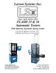
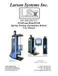
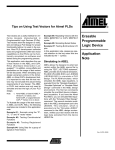
Larson Systems Inc.
V200, V750 and V1500
Digital Valve Spring Tester
User Manual
Current for Software Version 6.9
About This Manual
This manual could contain technical inaccuracies or typographical errors. Changes are
periodically made to the information contained herein. These changes will be incorporated in
new editions of the manual.
Copyright © 2010 Larson Systems Inc.
All rights reserved. No part of this manual may be reproduced by any means without written
permission of the author, except portions necessary for internal use only by the purchaser of
the LSI system.
V-Series Valve Spring Tester User Manual
Page 2 of 2
060-1000-0025-01
1 INTRODUCTION................................................................................................................... 4 1.1 V200, V750 or V1500 Precise Digital Tester................................................................................................. 4 1.1.1 Standard Features .................................................................................................................................... 4 1.1.2 Options ..................................................................................................................................................... 4 1.1.3 Force and Length Specifications .............................................................................................................. 5 2 SAVE YOUR PACKAGING! ................................................................................................. 5 3 QUICK START GUIDE ......................................................................................................... 5 4 SAFETY AND USE ............................................................................................................... 6 4.1 Installation ...................................................................................................................................................... 6 5 USER GUIDE ........................................................................................................................ 8 5.1 General Startup .............................................................................................................................................. 8 5.2 The Control Panel .......................................................................................................................................... 8 5.3 Test Modes ..................................................................................................................................................... 9 5.3.1 Manual ...................................................................................................................................................... 9 5.3.2 Peak.......................................................................................................................................................... 9 5.3.3 Shunt Calibration ...................................................................................................................................... 9 5.4 Force and Length Initialization ................................................................................................................... 10 5.5 Double Adjust Length Stops (optional) ..................................................................................................... 10 5.5.1 Setting the Stops .................................................................................................................................... 10 5.6 Testing Procedure ....................................................................................................................................... 11 5.6.1 Preparation ............................................................................................................................................. 11 5.6.2 Compression........................................................................................................................................... 12 5.6.3 Using Valve Spring Retainers................................................................................................................. 12 5.6.4 Parallelism Check ................................................................................................................................... 12 5.6.5 Deflection Compensation Check ............................................................................................................ 13 5.6.6 Length Calibration Check ....................................................................................................................... 13 5.6.7 Force Calibration Verification.................................................................................................................. 13 6 MAINTENANCE.................................................................................................................. 13 6.1 General.......................................................................................................................................................... 13 6.2 Calibration .................................................................................................................................................... 14 6.2.1 Ship Tester to LSI ................................................................................................................................... 14 TITLE ........................................................................................................................................ 15 WARRANTY ............................................................................................................................. 15 V-Series Valve Spring Tester User Manual
Page 3 of 3
060-1000-0025-01
1
INTRODUCTION
The V-Series valve spring testers are high precision machines designed for compression
spring testing of force and length.
1.1 V200, V750 or V1500 Precise Digital Tester
The V200, V750 and V1500 models are lightweight. An optional battery is available for ontrack use. Standard features include:
1.1.1
•
•
•
•
•
•
•
•
•
•
•
•
•
•
•
•
•
•
Force capacities of 200, 750 or 1500
pounds
5-inch stroke travel and range
measurement
Compression testing of force and
length
Deflection compensation for accurate
testing
Mechanical and software overload protection
Digital calibration and linearization
Backlit digital LCD display of force and length
Rack and pinion drive for convenient hand
operation
Wipe-clean embossed key faceplate
Push-button force and length zeroing
Push-button English or Metric unit selection
NIST traceable calibration
High-resolution force and length
Long-life rechargeable NiCad battery
RS 232 output to PC or printer
Cast-aluminum and steel frame housing for
durability
Two-inch diameter load platforms with a 5/16 –
18 thread center for mounting fixtures
Built-in shunt calibration verification
1.1.2
•
•
•
•
•
•
•
Standard Features
Options
Double stop rod attachment
Valve spring sorting and certifying spreadsheet interface software
Traveling case
8-piece valve spring retainer set
Micro-adjust with integrated stop rod
Battery for mobile use
RS232 cable for sending data to a printer
V-Series Valve Spring Tester User Manual
Page 4 of 4
060-1000-0025-01
Power Adapter
RS 232
Connection
(View of Back)
RS 232 to Parallel Printer
Cable and Adapter
1.1.3
Force and Length Specifications
V-Series – Force
Specifications
Capacity
Force
Resolution
**High Resolution
Length
110 lb
0.05 lb
0.001 in
200 lb
.10 lb
0.001 in
750 lb
0.5 lb
0.001 in
1500 lb
2
V-Series – Length
Specifications
1.0 lb
0.001 in
Accuracy = ± Resolution x 2
SAVE YOUR PACKAGING!
Your spring tester was shipped in packaging custom designed to protect the instrument. Use
this packaging when you need to ship your tester to LSI for periodic calibration.
3
QUICK START GUIDE
1. Warm up the tester for 30 minutes before using.
2. Initialize (zero) the tester to Zero Length and Zero Force (see 5.4).
3.Place a spring on the lower platform.
4. Use the handle to compress the spring to the specified length and read the force.
V-Series Valve Spring Tester User Manual
Page 5 of 5
060-1000-0025-01
4
SAFETY AND USE
Warning: A compressed or extended spring has stored potential energy proportional to the
spring constant. To avoid injury release this energy in a controlled manner when testing and
wear appropriate eye protection. Also, use approved fixtures to prevent springs from flying out
due to buckling under load. (Fixtures include extension hooks, larger platforms, buttons, etc.)
Do not apply more force than the tester can handle. Although equipped with software and
hardware overload stops, damage to the tester can occur. Release the force quickly and
safely if MAXIMUM FORCE is reached.
4.1 Installation
A dry, non-humid, non-condensing environment kept at room temperature 20° C ± 5° C
(68° F ± 9° F) is suggested when choosing a workstation for operating the tester. This
location should offer protection from debris or falling objects or anything that may damage
or interfere with the operation of the tester. Keep in mind accessibility to a printer and
power outlet depending on the tester’s capabilities. Be sure the operating location is clean
and dry and all parts to be tested are free of oil and contaminants.
Once a workstation location is selected:
• Place the tester on a level and stable work area where the operator can perform
compression testing in a comfortable manner. We recommend that you secure it to the
work surface.
• Insert the end of the Handle through the hole to the left of the Handle Release Lever.
Tighten the Handle Release Lever when in position. The Handle moves the Upper
Platform and is also used to apply force. Remove and reinstall at the next 90-degree
slot for convenience in testing.
V-Series Valve Spring Tester User Manual
Page 6 of 6
060-1000-0025-01
Optional
Compression
Stop Rod*
Optional Compression
Stop Rod*
Sliding Stop Lock
Stop Rod
Clamps
Handle Release
Knob (or Lever)
Stroke (Length) Lock
Handle
Upper Platform
Overload Stop
Screws
Lower Platform
Control Panel
•
•
•
The Stop Rods may be installed and stops set later.
The Stroke (or Length) Lock on the left side is holds the upper platform at a desired
length under load up to 300 lbs. This feature simplifies setting length stops.
The Overload Stop Screws on top of the tester base near the Lower Platform are set
and sealed at the factory and should never be tampered with.
V-Series Valve Spring Tester User Manual
Page 7 of 7
060-1000-0025-01
5
USER GUIDE
5.1 General Startup
Commands using the keypad buttons will refer to the button in CAPITALIZED BOLD
LETTERS in brackets [ ] throughout the manual.
Turn on the testing unit by pressing [ON / CLEAR]. The tester will respond by lighting and
first displaying:
LARSON SYSTEMS
Next it will display:
V750# v6.9
LENGTH RES .0010
The first line in the example above shows the model designation (VXXX), force capacity
(1500#), and the software version (V6.9) used to configure the tester. The second line
indicates the tester’s length resolution (.0010). In the next display that appears, the first
line displays “ZERO LENGTH” indicating that the [ZERO
ZERO LENGTH
LENGTH] button should be pressed to activate the length
0.000
lb
reading function on that line. The force display on the second
P 0.00 in lb
line should show zero or a small reading. Press [ZERO LENGTH] to activate the length
reading function, if available.
The display defaults to the Manual testing mode and the last unit of measurement used on
the tester before it was turned off. Learn about the control panel in the next section.
5.2 The Control Panel
[UNITS] Choose unit of measurement – lb, N, oz, or kg for force and in or mm for length.
[MODE] Select the test mode that applies. The test modes available are: Manual and
Peak. A mode for Shunt calibration verification is included.
[ZERO FORCE] Zero out the current force reading displayed.
[ZERO LENGTH] Zero out the current length reading displayed.
[SEND] Send displayed reading to PC or printer
[ON / CLEAR] Turns on the tester and resets Peak mode.
V-Series Valve Spring Tester User Manual
Page 8 of 8
060-1000-0025-01
[OFF] Turns the tester off. Turn the tester off when not in use to conserve battery life.
5.3 Test Modes
Either Manual or Peak mode may be used for testing. A third mode, Shunt calibration
verification, is not used for testing.
When the machine is first turned on, it defaults to Manual mode. Press [MODE] to enter
Peak mode, and again to enter Shunt calibration mode.
Each of the modes is described in the following sections:
5.3.1
Manual
The Manual (tracking) mode displays the current force and length during testing and
dynamically adjusts as force recedes or increases. The length lock may be tightened at
a desired measuring point to hold the upper platform in place and fix the reading on the
display for recording purposes. Press [SEND] to record the data in a printable format
and continue testing.
5.3.2
P
Peak
2.300 in
87.70
lb
0.00 in lb
The Peak mode is indicated by “pk” in the lower left of the display as shown below.
This testing mode is standard on all models. When testing in this mode, the display
dynamically adjusts to reflect the force and length measurement as the force applied
increases. When the force applied recedes, the display locks in at and displays the
highest force reading that occurred, along with the corresponding length (if applicable).
If a greater force is subsequently applied, the display will continue to adjust to a force
that exceeds the previous reading but will not adjust to a lesser reading.
pk
P
2.000 in
92.85
lb
0.00 in lb
To reset the display reading, press [ON / CLEAR]. If the display does not return to zero
or near zero, press [MODE] to exit Peak mode. Press [MODE] again to enter the
Manual mode. Press [ZERO FORCE] with no force applied while in the Manual mode
to zero the display. Return to peak mode to proceed.
5.3.3
Shunt Calibration
The Shunt mode is indicated by “shn” in the lower left of the display as shown below.
This mode does not apply to testing but to the calibration of the testing unit and is used
to verify the accuracy of force readings.
The tester should be warmed up and the force display zeroed in the Manual mode
before entering the shunt calibration mode for verification. Make sure the unit of
measurement is the same as the Shunt Value recorded on the Calibration Report from
the factory. When the shunt calibration mode is activated, a load is electrically
simulated and generates a force reading on the display. Compare the force value
displayed in the underlined field shown in the example below with the Shunt Value
V-Series Valve Spring Tester User Manual
Page 9 of 9
060-1000-0025-01
recorded on the Calibration Report shipped with the tester. The two numbers should
match or be relatively close. Contact Larson Systems if there is a notable discrepancy.
3.931 in
shn
65.15
lb
P 0.00 in lb
5.4 Force and Length Initialization
The force and length displayed must be initialized (zeroed) at a reference point to achieve
consistent results. This should be done prior to testing.
The normal reference point for force is with the platforms apart and no load (spring) on the
lower platform. However, force initialization may also need to be done after the normal
initialization with the sample spring resting on the lower platform. This ensures the weight
of the test spring is not included in the force measurement. The test procedure includes
this step.
The normal reference point for length is with the upper and lower platforms together
(compression), with force applied.
If stop rods are part of the tester’s assembly, make sure the rods are set to permit free
travel of the upper platform before initializing.
1.
2.
3.
4.
5.
Turn on tester and move the upper platform all the way upward.
There should be no force applied and nothing resting on the lower platform.
Press [ZERO FORCE]. The force display should read zero.
Bring the upper platform down to meet the lower platform.
With the platforms together and applying 10-30% full-scale force, press [ZERO
LENGTH].
5.5 Double Adjust Length Stops (optional)
Repetitive testing at one or two specified lengths is made simple through use of the Double
Adjust Length Stop system that includes one or two threaded stop rods, a dual clamping
top support and a sliding stop block. Initialize the tester (section 5.4) before setting the
stops so the length readings are accurate.
5.5.1
Setting the Stops
1.
2.
3.
4.
Place the spring on the lower platform
Determine two specific lengths for measurement based on the spring
Move the sliding stop block all the way to the left
Adjust the upper platform to the longer measurement length and lock platform at that
length by tightening the length lock lever
5. Adjust the left stop rod to meet the sliding stop block at that length and tighten the
left stop rod clamp
6. Release the length lock and move the sliding stop block to the right
7. Adjust the upper platform to the shorter measurement length and lock platform at
that length by tightening the length lock lever
V-Series Valve Spring Tester User Manual Page 10 of 10
060-1000-0025-01
8. Adjust the right stop rod to meet the sliding stop block at that length and tighten the
right stop rod clamp (the left stop rod passes through the sliding stop block)
9. Release the length lock
Left Compression Stop Rod
Right Compression Stop Rod
The tester is now ready to do repetitive testing of like samples at two lengths by just
applying force until the platform stops and then moving the sliding stop block over for
the next reading. This allows you to test several samples very quickly. If one length stop
measurement is required, use just one stop rod to set. The stops are easily removed for
normal operation.
5.6 Testing Procedure
5.6.1
Preparation
1. Turn on the tester and allow it to warm up for at least 30 minutes prior to testing.
2. Check out the operating condition of the tester. Make sure the upper assembly
moves freely and all parts are in working order.
3. Exercise the machine in the way that testing will be done to facilitate the most
accurate readings.
4. Leave the tester in Manual mode to begin.
V-Series Valve Spring Tester User Manual Page 11 of 11
060-1000-0025-01
5.6.2
Compression
1. Choose the unit of measurement to be used
for testing by pressing [UNITS].
2. Initialize both force and length for
compression per instructions in section 5.4.
3. Place the spring on the lower platform
without applying force and press [ZERO
FORCE]. This deducts the weight of the
spring from the force measurement.
4. To test in Peak mode, press [MODE]. The
lower left of display reads “pk”. Otherwise,
remain in Manual mode and begin testing
with the next step.
5. Perform test by applying compressive force
to sample using the handle on the upper
rack assembly. Use standards you
previously determined appropriate for
desired results to complete the test.
6. The resulting data may be sent to a printer
at the measurement point by pressing
[SEND]. If preferred, manually record the
data. If sample passes or fails test, remove from platform and sort as needed.
7. Press [ON / CLEAR] to reset the display. If you are testing in Peak mode and the
display will not zero, you will need to zero it in the Manual mode. Then return to
Peak mode to continue testing.
8. Repeat procedure from step 3, making sure the force display reads zero with sample
on platform with no force applied as instructed.
When length is initially zeroed, it should not be necessary to initialize length again
before testing additional samples, unless [ZERO LENGTH] is pressed when platforms
are apart.
5.6.3
Using Valve Spring Retainers
A set of eight (8) valve spring retainers is
available from Larson Systems Inc. Use
them to get more accurate readings on
double or triple valve springs.
5.6.4
Parallelism Check
The upper platform must be parallel with
the load cell (lower platform) to achieve
reliable readings. Parallelism directly
affects length accuracy and should be
verified prior to verifying the length calibration. This procedure requires using a dial
V-Series Valve Spring Tester User Manual Page 12 of 12
060-1000-0025-01
indicator for parallelism measurement. If a dial indicator is not available or length data
is not required, this procedure may be omitted.
5.6.5
Deflection Compensation Check
1. With no force applied, press [ZERO FORCE].
2. Bring the upper platform down to meet the lower platform. While applying about 5%
full-scale force, press [ZERO LENGTH] to initialize.
3. Place a 0.1-inch gage block between the upper and lower platform.
4. Apply 5% and 95% full-scale force and record the deflection length for compression.
The length displayed should read the same at 5% and 95% within .001 of an inch.
5.6.6
Length Calibration Check
1. Bring platforms together and press [ZERO FORCE] while applying a known force
near 50% full scale to initialize. Remove force.
2. Place a 0.1-inch gage block between the load cell and upper platform.
3. Apply the same known force used to initialize the tester in step 1 and record the
gage block length and displayed length.
4. Repeat step 3 inserting gage blocks increasing length to 1, 2, 3, 4, 5, and 6 inches.
5.6.7
Force Calibration Verification
1. Move the upper platform to its maximum height.
2. Press [ZERO FORCE] to zero the display.
3. Apply known loads in ascending order in 10 equal increments up to full scale and
record the results.
4. Reapply the loads at least three times to establish repeatability.
5. Evaluate the results. The results should be within the accuracy specifications found
in the corresponding force specification table for the tester in section 1.
6
MAINTENANCE
6.1 General
The V-series Valve Spring tester is a low maintenance tester. We recommend that oils and
other liquids be kept away from and off of the electronics portion of the tester. If liquid or oil
should contact the device, wipe it off with a soft cloth or paper towel. Never apply any
cleaner or solvent directly to the electronics faceplate; a mild plastic cleaner applied to a
wipe may be used. Take measures to protect the tester from debris or falling objects; the
load cell contains sensitive electronics and can be severely damaged by such forces.
V-Series Valve Spring Tester User Manual Page 13 of 13
060-1000-0025-01
6.2 Calibration
We recommend that you have your tester calibrated for NIST traceable certification on an
annual basis. Frequency of calibration can be based on how often and for what purpose
the tester is used. Contact Larson Systems to schedule calibration service as needed.
6.2.1
Ship Tester to LSI
The tester may be shipped to LSI in its original packaging container for calibration with a
usual turnaround time of less than one week. Our address is:
Larson Systems Inc.
10073 Baltimore St. N.E.
Minneapolis, MN 55449
To schedule calibration, call 1-877-780-2131. Send the tester to us freight prepaid.
V-Series Valve Spring Tester User Manual Page 14 of 14
060-1000-0025-01
TITLE
Title to the described equipment shall remain in the seller until full, actual payment therefore
shall have been made. In the event of a default, the seller shall have the right to repossess the
said equipment and whatever monies shall have been paid on account shall be deemed to
have been rental for the use thereof to the date of such repossession. The seller shall also
have the right to hold the purchaser liable for a sum equivalent to the unpaid balance of the
purchase price together with all expenses and damages that the seller may have sustained,
the purchaser to receive credit however, for the net monies realized on the sale of the
equipment. At the election of the seller, the seller may deem title to have passed to the
purchaser, in which event the seller need not repossess the equipment, but may sue at law for
the balance unpaid thereon.
WARRANTY
The V-series Valve Spring Tester parts and labor are warranted against defects in material and
workmanship to the consumer for a period of twelve months from the date of purchase. This
warranty covers all parts, except consumable items. It applies only to machines and
accessories which have been installed and operated in accordance with instructions in our
reference manuals, have not been tampered with in any way, misused, suffered damage
through accident, neglect or conditions beyond our control and have been serviced only by
authorized personnel. Larson Systems Incorporated is not responsible for loss in operating
performance due to environmental conditions, such as humidity, dust, corrosive chemicals,
deposition of oil or other foreign matter, spillage or other conditions beyond our control. There
are no other warranties expressed or implied, and Larson Systems Incorporated shall not be
liable under any circumstances for incidental or consequential damage. Warranty service is
conducted at LSI’s facilities in Minneapolis, MN. Return the tester freight prepaid during the
warranty period, and Larson Systems Incorporated will make a warranty determination, repair
and return the tester freight collect. Shipments sent collect will be rejected.
V-Series Valve Spring Tester User Manual Page 15 of 15
060-1000-0025-01
Larson Systems Inc. 10073 Baltimore Street NE Minneapolis, MN 55449‐4425 763‐780‐2131 Fax: 763‐780‐2182 1‐877‐780‐2131 www.larsonsystems.com [email protected] V-Series Valve Spring Tester User Manual Page 16 of 16
060-1000-0025-01