1
Operability
Central operation by master unit
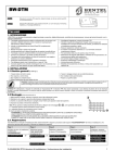
A wide range of settings and control functions
Digital display panel
LED lamp
LED lamp indicates a function that can
be selected.
(Selected function flashes on the display)
Front
Ease of use enables smooth working on site.
Ch : For selecting channels
Brt : For setting light control data
(constant lighting type only)
Pls : For setting the pulse width
Dly : For setting the delay time
(strobe type only)
Opt : For setting optional functions
Terminal unit
The Terminal Unit is inserted at the rear
end of the unit.
※Caution
Do not remove the Terminal Unit while the power is turned
on. Doing so may damage the system.
Panel buttons
Output connector
The unit can be operated by the panel
buttons. Reliable one-touch settings
improvs operability.
Employs a connector with a new configuration.
Used for connections with lighting units via the
dedicated cable included. Two types are
available for 12V and 24V lighting.
…Select button
SEL
Select the function desired to be set.
Output connector
Pin configuration
B1
…Numerical value setting buttons
(up/down buttons)
B2
B3
Pin number
…Range button
RANG
Shifts the digits of numerical values.
…Enter/lock button
ENT/
LOCK
Confirms a function or numerical value.
When this button is pressed and held down,
it is locked, and when it is held down again,
lock is released.
A1
A2
A3
Description
A1
L ED I D
A2
Nothing to be
connected
A3
Nothing to be
connected
B1
Output+24V
B2
Output+12V
B3
COM
Items included
Terminal configuration
•Intermediate cable for 12V lighting for
12V output units.
•Intermediate cable for 24V lighting for
24V output units.
Equipped with a DC24V input terminal,
a trigger signal input terminal, and an
FG terminal.
Terminal block
TRIG+
24V+
4
1
24Vー
5
2
ー
TRIGー
6
3
Bottom
FG
ID setting switch
All the units can be registered by ID numbers.
Pin configuration
Pin number
Description
1
24V+
2
24Vー
3
FG
4
TRIG+
5
TRIG ー
6
Nothing to be
connected
Recommended crimp terminal : NICHIFU M3 crimp
terminals with insulating sheath Ring or “Y” TMEV
1.25-3
Mounting screw hole for mounting to stand.
Used for mounting the unit instead of
DIN rails.
Also used for mounting to the optional
stand.
Mounting screw hole for connecting parts.
Use the attached connecting parts when
fixing units.
※ See the User Manual for details related to each item.
7
Operation conditions can be checked and
set values can be controlled easily.
Also equipped with an error display function
that notifies the user by error code when any
errors occur.
ON
1
2
3
4
Switch positions for setting ID numbers
No. 0
No. 4
No. 8
No. 12
No. 1
No. 5
No. 9
No. 13
No. 2
No. 6
No. 10
No. 14
No. 3
No. 7
No. 11
No. 15
※Caution
Make sure that the power is turned off before setting
ID numbers.
Setting numbers with the power ON may damage the
system.
Points when setting ID numbers
ID numbers at the time of shipment are set
at 0 for all units.
When adding a unit, set the master unit at
ID No.0, and set the other units at ID No.1,
2,3 etc. in the order of coupling, in order to
allow for easy operation and control.