1
Freescale Semiconductor, Inc.
Software Implementation
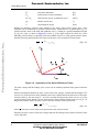
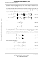
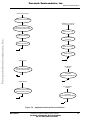
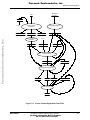
In the case presented, the output voltages are divided into six sectors; (see Figure 7-17.). The current
is then calculated according to the actual sector value:
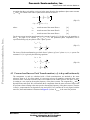
for sectors 1, 6:
iA = – i B – iC
(EQ 7-5)
iB = – i A – iC
(EQ 7-6)
iC = – i B – iA
(EQ 7-7)
for sectors 2, 3:
Freescale Semiconductor, Inc...
for sectors 4, 5:
Notes:
The sector value is used only for current calculation and has no other meaning at the sinewave
modulation. But if any type of the space vector modulation is used, the sector value can be
obtained as a part of space vector calculation and used for phase current measurement.
7.6.2 Voltage Sensing
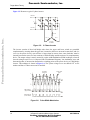
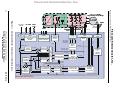
The resistor divider network in Figure 7-18 is used to sense the DCBus voltage. The voltage signal is
divided down to the 3.3V level and is ready for further processing. DCBus voltage does not change
rapidly. It is almost a constant, with ripple caused by the structure of the power supply. If a bridge
rectifier for conversion of the AC line voltage is used, the ripple frequency is twice the AC line
frequency. Ripple amplitude should not exceed 10% of the nominal DCBus value if the power stage is
designed correctly.
DC bus positive
330k-1%
R224
270k-1%
R225
6.8k-1%
R226
R228
6.8k-1%
220k-1%
R227
R229
270-1%
+
C208
22nF/630VDC
3.24V @
C209
470uF/400V
DC-Bus = 400V
V_sense_DCB
R230
6.8k-1%
DC bus negative
GNDA
Figure 7-18. DC-Bus Voltage Sensing
The measured DCBus voltage must be filtered in order to eliminate noise. One of the easiest and
fastest techniques is a first order filter, which calculates the average filtered value recursively from the
last two samples and a coefficient C:
u DCBusFilt ( n + 1 ) = ( Cu DCBusFilt ( n + 1 ) – Cu DCBusFilt ( n ) ) – u DCBusFilt ( n )
56
3-Phase AC Induction Motor Vector Control
For More Information On This Product,
Go to: www.freescale.com
(EQ 7-8)
MOTOROLA