1
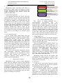
Iraq J. Electrical and Electronic Engineering Vol.10 No.2 , 2014 اﻟﻤﺠﻠﺔ اﻟﻌﺮاﻗﻴﺔ ﻟﻠﻬﻨﺪﺳﺔ اﻟﻜﻬﺮﺑﺎﺋﻴﺔ واﻻﻟﻜﺘﺮوﻧﻴﺔ 2014 ، 2 اﻟﻌﺪد، 10 ﻡﺠﻠﺪ to be transmitted through it, most manufacturers have made the OBD-II Data Link Connector the only one in the vehicle through which all systems are diagnosed and programmed. OBD-II Diagnostic Trouble Codes are 4-digit, preceded by a letter: P for engine and transmission (Powertrain), B for body, C for the chassis, and U for the network. Fig. 3 shows the pin configuration of OBD connector and Table. I is the description of these pins. IV. SYSTEM FEATURES The system has many combined features that make the driving safer, maintenance faster, avoid stealing of a vehicle, and eases the reaching of the destination which will save fuel and time. Fig. 4 briefly shows these features. Early Warning Remote Fault Diagnosis Vehicle Tracking Traffic Control Safety vehicle ID verification Environme nt friendly Fig. 3 OBD Connector Shape Fig. 4. System Features For example, if the vehicle has pin numbers 2, 4, 5, 10, and 14 populated, then the vehicle will be using the SAE-J1850 protocol (and this vehicle was made by Ford). Early Warning The system has the ability to display and send an early warning message to the driver and the monitoring center. According to the sensor’s measurement some faults can be predicted by the system based on car history and experience data base. A. As a ―rule of thumb‖, Ford vehicles use the SAE-J1850 PWM protocol, Japanese vehicles use ISO 14230, Chrysler and other foreign vehicles use ISO 9141, and GM uses SAE-J1850 VPW. The exception to this are vehicles that are year 2005 (some not all vehicles 2005-2008) or newer (2008 and newer for certain as CAN bus was mandated in 2008) as these vehicles all use the CAN bus. However, even if a vehicle uses the CAN bus, there are multiple CAN bus protocols. To determine exactly which CAN bus protocol the STN1110 is using, you will have to rely on the software running on the master device reporting then protocol being used [9]. Vehicle Tracking The system uses a GPS card to find the vehicle’s location and speed. This information will be used by the system for tracking the vehicle for many reasons. The first is to track the vehicle in case the car got stolen and the second is to find the nearest maintenance center in case help was needed. B. Remote Fault Diagnosis Fault codes and sensor’s measurement are read as required by the system via the OBD connector. These codes and sensor readings are sent to the monitoring center if required to evaluate the vehicle status and make a decision if the vehicle can be fixed on location and what spare parts are required or if it needs to be loaded to the nearest maintenance center. C. Table I OBD-II Pin Configuration Pin Number 1 2 3 4 5 6 7 8 9 10 11 12 13 14 15 16 Function Single-Wire CAN, J2411 Bus + of SAE-J1850 PWM or VPW Not used on adapter Chassis Ground Signal Ground CAN High, ISO 15765-4, SAE-J2284 K-line of ISO 9141-2 and ISO 14230-4 Not Used Not Used Bus – of SAE-J1850 only Not used on adapter Not Used Not Used CAN Low, ISO 15765-4 and SAE-J2284 L-line of ISO 9141-2 and ISO 14230-4 Battery Positive Safety One of the most important sensors that need to be read periodically by the system is the airbag’s sensor. The system will send a high priority warning message to the monitoring center that includes the vehicle’s location if the vehicle’s airbag is activated. The monitoring center employer can use the system GSM modem to make a call to the driver and checks if the driver can answer or not before sending help. D. 57