1
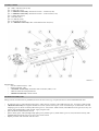
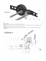
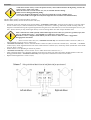
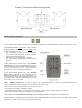
caravan mover
user`s manual
Safety precautions
Read this manual before fitting or first use
Use only approved jacking equipment when fitting
Check the tyres pressure and condition (new tyres recommended)
Check the chassis is in undamaged, rust-free condition
Apply caravan hand brake before fitting
Always apply caravan hand brake prior to disengagement of drive rollers and after the mover
operation is complete (you cannot rely on rollers to act as hand break)
Apply torque settings specified
Perform a dry run in an open area after fitting to familiarise yourself with mover`s operations
Keep the remote out of reach of children
If you have bought a Manual Version Mover you can easily upgrade to Automatic Version at a later date. It is as simple as fitting
roller actuators and Automatic Roller Control box (ARC). Your Caravan Control system (CC) and the remote will automatically
recognise the upgrade and are ready to work. Ask your dealer for further details.
Technical spec
caravan max weight
2000 kg (20% slope)
weight without battery
33kg (Manual Version: 36 kg)
velocity
appr. 15cm/s
min battery capacity
80Ah 12V DC
Chassis critical dimentions
Standard kit allows fitting to vast majority of caravans available (will fit both L-plate type and U-plate type chassis).
If in any doubt please check that the chassis of your caravan complies with dimentions:
*if „x” and/or „h” measurement is out of those given above („x” is lower than 170 mm (see schemes A) or „h” is higher than 18 mm
(see schemes B)) custom spacers will be required (available on request – supply your dealer with appropriate measurements of your
caravan chassis)
Tools needed
–
–
–
–
–
open-end or ring 10 mm wrench: 2 No
open-end or ring 13 mm wrench: 2 No
open-end or ring 17 mm wrench: 1 No
small pozi/cross screwdriver
torque wrench
Assembly contents
pos. 1 and 2: side drive unit (2 No)
pos. 3: centre bar (1 No)
pos. 4: <Manual Version only> hollow box section – extention (2 No)
pos. 5: <Manual Version only> hollow box section – centre section (1 No)
pos. 6: clamp plate (2 No)
pos. 7: bracket (2 No)
pos. 8: U-bolt kit (2 No)
pos. 9: stop block kit (2 No)
pos. 10: <Manual Version only> Hex screw M8x35 with nut (2 No)
Scheme 2
Supplied also:
– caravan control unit (CC): 1 No
– remote controller: 1 No
– <Automatic Version only> automatic roller controller (ARC): 1 No
–
cable set/connectors/crimps/cable ties
– <Manual Version only> 19mm wrench
Mechanical assembly order
Fitting in front of caravan axle is preferable, however in some cases (e.g. no space) the mover can be fitted behind the axle.
–
–
–
–
–
fit centre bar (pos. 3) into both drive units (pos.1 and 2). Screw in loosely 4 No of M10 screws (pos. 14) with a 17mm wrench.
<Manual Version only> Fit together hollow box section (centre section pos.5, 2 No of extention pos. 4) and slide it onto side
couplings (pos.12). Screw in loosely M6 screws (pos.13; 4 No) with a 10mm wrench, insert M8x35 screws (pos.10; 2 No), use
nylock nuts supplied and a 13mm wrench. Apply torque 27 Nm.
place the Mover underneath the caravan
place U-bolts (pos.8; 2 No) through clamp plate (pos.6), bracket (pos.7), thick washer (pos.15; 4 No) and secure loosely with
supplied M10 nylock nuts (pos.16; 4 No). Use a 17mm wrench.
Repeat procedure with the other side drive unit
–
–
–
–
–
allign the mover as on scheme 5. Use supplied wooden blocks (pos.20) to determine the correct clearance between caravan`s tyre
and drive rollers
tighten up nylock nuts (pos.16; 8No) to 25Nm with a 17mm wrench.
Move stop block (pos.9) to bracket (pos.7) and tighten up M10x35 screw and nut and secure with M10 counternut to torque
50Nm.
Tighten up M10 screws (pos.14; 4No) to 12Nm with a 13mm wrench.
<Manual Version only> Tighten up M6 screws (pos.13; 4No) to 12Nm with a 10mm wrench and secure with supplied
counternuts.
Scheme 6
Electronic control system assembly and operations
It is recommended to use a battery of minimum capacity of 80 Ah.
Ensure the battery is fully charged before operation.
Mind that all batteries discharge slowly with time on their own.
Procedure
Avoid short-circuits! Always secure the positive battery cable with an insulator during fitting. Connect the
positive battery cable as last cable.
Check the electronic caravan control box (CC) is switched off before fitting.
Rollers must be disengaged during fitting.
Control box should be installed in a dry place, best inside the caravan, enabling access.
Never shorten/add extra lenght of aerial (stock length has been tuned for best communication)
Thicker cables (10mm2) connect the battery with (CC).
Thinner cables (6mm2) connect the drive motors with (CC).
–
lead all the wires from left/right motors and the battery <Automatic Version only: and wires from actuators> to the area where
caravan control box (CC) will be installed (most commonly in front boot or inside e.g. under bed); instead of cutting cables to
length we recommend leaving the original length and securing the excess with cable ties (in case of transfering the mover to your
next – bigger caravan you may need longer cables); in case of cutting cables new cable crimps should be used.
Ensure cables do not chaff especially when led through caravan`s floor (use protective grommet, tape, tube
sleeve or the like if necessary – not supplied). Use cable ties to secure cables.
Remember to leave a length of slack cable by the drive motors to allow for rollers` engagement/
disengagement movement.
–
–
–
–
–
– Secure caravan control box (CC) <Automatic Version only: and Automatic Roller Control box (ARC)> in
place and undo 4 screws on (CC) to remove lid.
<Automatic Version only> connect Automatic Roller Control box (ARC) to Caravan Controller (CC). Use PWR - + and RS485
socket on (CC). Insert supplied 20A fuse into socket inside Caravan Controller (CC). Ensure dip switch (beside fuse socket inside
CC) is at „RCU” position.
Follow scheme 7 or 8 depending on the mover position
<Automatic Version only> connect actuator wires to ARC. Red colour connectors are „+”
After connecting all the wires check the operations of the mover by observing rollers movement (double-check the rollers are
disengaged beforehand). <Automatic Version only: check operation of IN/OUT movement of the rollers>
Replace lid and tighten the 4 screws on (CC)
Remote control operating manual
1. To switch the remote ON press simultaneously
+
buttons for about 3 sec.
All three LEDs (bi-colour LEDs are used) light up durring pressing. Remote switches Off after no button has been pressed for 1 min.
2. Range/Remote battery level LED: (LED signalling
normally in green; when remote battery level is low, LED
signalling changes to red. There is min. 2 working hours
left after LED changes to red).
− when remote out of range (or caravan control box
(CC) switched Off) LED flashes in series of 4 times
fast/no flash (searching for signal);
− when remote in range LED is lit up (constant);
− fast LED flashing indicates Drive buttons buttons
pressed.
3. Auto rollers IN/OUT buttons (active with Automatic
Version only): press both buttons simultaneously to move
rollers IN or OUT of the tyres. Rollers will stop as soon as
the correct individual pressure on tyre is achieved (useful if
both caravan tyres are not pressurised identically).
4. Auto Rollers STOP button (active with Automatic
Version only): during IN or OUT movement of Auto
Rollers press this button to stop such movement (e.g. in
case of emergency). After such stoppage the next time both
Auto rollers IN/OUT buttons are pressed the rollers will
always return to OUT position first.
NOTE <Automatic Version only>: in case of a failure (e.g. discharged main battery) slide rubber grommets off the back of
actuators and wind the actuators separately out of the wheels using 8mm hex key.
5. Main (mover) battery level LED (active only when remote in range):
- green LED lit up (constant): main battery charged;
- red LED flashing: main battery appr. half-empty; needs charging, however system still fully operative for some time.
- red LED lit up (constant): main battery level too low; system inoperative.
6. Alert LED (active with Automatic Version only): green LED flashing indicates Auto Rollers IN or OUT movement.
Both Main battery level LED and Alert LED flashing in green and red simultaneously indicate overload (may happen under extreme
conditions eg. very heavy caravan trying to drive past a steep kurb).
Manoeuvring
You can manoeuver your caravan/trailer in directions represented by buttons with arrows on the remote. Pushing a button is
confirmed by fast-flashing of Range/Remote battery level LED. Your caravan/trailer can be moved:
backwards right
forwards right
backwards
forwards
backwards left
forwards left
It is also possible to spin your caravan/trailer by means of
pushing simultaneously (active only with single axis
version only):
+
spin right
+
spin left
Caravan Control box (CC) operations
Switch ON power switch on the caravan control box (CC) to activate the system. Green LED on (CC) blinks for 3 sec (internal selftest). Continuous green LED illumination denotes sytem ready to work. Green LED on (CC) flashes fast when receiving signal from
the remote.
Flashing red LED on (CC) indicates main battery low (appr. half-empty). It is still possible to operate the system with red LED
flashing, however it is recommended to charge the battery as soon as possible. Continuous red LED illumination denotes flat battery –
the system is inoperative (no reaction to the remote). Charge main battery.
System goes into stand-by mode after 2mins of no operation (reverts to normal mode if any signal received from remote). Although
stand-by mode consumes minimal energy the power should be switched off if mover not intended to be used for a longer time (e.g.
after holiday).
By overload operations of the system are suspended for 10 sec (both green and red LEDs flash simultaneously). Systems
resumes operation after that time if the cause of overload removed which is confirmed by continuous green LED illumination
(red LED indicates main battery level irrespectively).
Synchronising remote with main control box
Your Combi Mover control system comes ready to use. However, you will need to re-synchronise the remote with caravan control
box (CC) in case of replacing either of them. Synchronising procedure creates a unique connection code assigning the remote to the
particular (CC)(which prevents possibility of interference with other movers in the area).
1. Apply caravan handbrake and disengage rollers
2. Connect remote with caravan control box (CC) using mini-jack cable (supplied).
3. Switch the (CC) and remote on
4. Push service button on (CC) (using a match or other thin-tipped item as the button is placed deeper in the case to prevent accidental
activation). Green LED beside the service button flashes slowly.
5. Push any arrowed button on the remote (green LED beside the service button flashes fast) and wait appr. 2 sec.
Syncronising procedure is completed when confirmed by continuous green LED illumination on (CC). Remove mini-jack cable –
system is ready to work.
In emergency (e.g. strong radio interference in the area or flat remote battery) you can cable-operate your caravan/trailer (signal from
remote passes via supplied mini-jack cable to main control box).