1
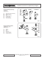
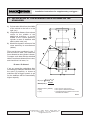
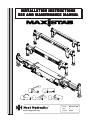
INSTALLATION INSTRUCTIONS
USE AND MAINTENANCE MANUAL
Boretto Reggio Emilia Italy
Code
Rev
Edition
MD.0.157 GB
1
10/08
- Installation instructions for supplementary outriggers -
INDEX
FOREWORD ........................................................................................................................................... page 1
MACHINE DIRECTIVE ................................................................................................................................ “ 2
REFERENCE NORMS ................................................................................................................................ “ 2
1
2
3
4
5
6
7
7.1
7.2
7.3
7.4
8
9
10
11
11.1
11.2
11.3
11.4
12
12.1
12.2
12.3
12.3.1
12.4
12.5
12.6
12.7
12.8
13
14
15
16
17
MAIN COMPONENTS AND TERMINOLOGY ............................................................................................... “
CYLINDERS FIXING SYSTEMS .................................................................................................................. “
CHOOSING THE STABILIZER .................................................................................................................... “
CALCULATION OF THE MAXIMUM FORCE ALLOWED ON THE STABILIZER ........................................... “
TABLE OF MAXIMUM FORCE RATES ALLOWED ON THE DIFFERENT “MAXISTAB” STABILIZERS ......... “
SUPPLEMENTARY OUTRIGGERS INSTALLATION .................................................................................. “
CHOOSING THE VERSION ....................................................................................................................... “
INSTALLATION ON THE CHASSIS
INSTALLATION UNDER THE CHASSIS
FIXING SYSTEM BY CLAMP COLLAR FOR SERIES “ ML ” - ” 0 " - “ 1 ” - “ 2 ” - “ 3 ” ............................... “
Supply conditions ....................................................................................................................................... “
Fixing instructions ...................................................................................................................................... “
Warnings and dangers ............................................................................................................................... “
Periodical checkings .................................................................................................................................. “
ASSEMBLING AND DISASSEMBLING OUTRIGGERS CYLINDERS SERIES “ 4 ”
STANDARD OR “ P ” VERSION WITH SYSTEM BY STOP RING .............................................................. “
Modification of a stabilizer series “ 4 ” standard version into “ P ” version .............................................. “
FIXING SYSTEM BY SPACER FOR OUTRIGGER CYLINDERS SERIES “ 5 ”, “ 6 ”, “ 7 ”, “ 8 ” ................. “
SPECIAL VERSIONS AND OPTIONALS .................................................................................................... “
“GIR” (tilting) version .................................................................................................................................. “
Swivel foot kit .............................................................................................................................................. “
Cylinders rod extensions ........................................................................................................................... “
Dual side controls kit c/w valve bank ......................................................................................................... “
HYDRAULIC CONNECTION OF “ MAXISTAB ” SUPPLEMENTARY OUTRIGGERS ................................. “
Lock valves on outrigger cylinders ............................................................................................................ “
Connection piping ...................................................................................................................................... “
Prescriptions for “ MAXISTAB ” hydraulic system ...................................................................................... “
Double on-line relief valve ......................................................................................................................... “
Hydraulic scheme for manual extendable stabilizers c/w one valve bank function
and “T” connection between crane and additional stabilizers ................................................................. “
Hydraulic scheme for manual extendable stabilizers c/w one valve bank function
and 5 ways/4 pos. diverter ......................................................................................................................... “
Hydraulic scheme for hydraulic extendable stabilizers c/w one valve bank function
and two 5 ways/4 pos. diverters ................................................................................................................ “
Hydraulic scheme for hydraulic extendable stabilizers c/w two independent 4 functions
valve banks (one for the crane and one for the additional stabilizers) .................................................... “
Hydraulic scheme for manual extendable stabilizers c/w two independent 2 functions valve banks ... “
HYDRAULIC CONNECTION OF THE ROD EXTENSION CYLINDERS
FOR MODELS “ 1 EHO “ – “ 2 EHO “ ........................................................................................................ “
INSTRUCTIONS FOR FIXING AND CONNECTING THE KIT MICROSWITCHES FOR
NOT LOCKED EXTENDABLE RODS ......................................................................................................... “
DECALS APPLICATION .............................................................................................................................. “
STORAGE AND HANDLING INSTRUCTIONS ........................................................................................... “
CAUTIONS TO OBSERVE .......................................................................................................................... “
TABLE OF WEIGHTS W/O PACKING ......................................................................................................... “
FINISHING AND PAINTING OF “ MAXISTAB ” STABILIZERS ..................................................................... “
Via Mediterraneo, 6 - 42022 - Boretto - Reggio Emilia - Italy
Tel. +39 - 0522-96 30 08 - Fax +39 - 0522-96 30 39
[email protected]
3
3
5
6
7
8
9
11
11
11
12
13
13
15
15
16
16
16
16
17
18
18
18
18
19
20
21
22
23
24
25
26
27
28
28
29
30
-
18
18.1
18.1.1
18.1.2
18.2
18.2.1
18.2.2
18.2.3
18.2.4
18.3
18.3.1
18.3.2
18.3.3
18.3.4
Use and maintenance manual
-
STABILIZERS’ USER MANUAL .................................................................................................................. “
Lateral extensions locking systems .......................................................................................................... “
Manually operated lateral extensions ....................................................................................................... “
Hydraulically operated lateral extensions ................................................................................................. “
Operating instructions ............................................................................................................................... “
General attentions ..................................................................................................................................... “
Hydraulic stabilizer ..................................................................................................................................... “
Manually tilting hydraulic stabilizer ............................................................................................................ “
Automatically tilting hydraulic stabilizer ..................................................................................................... “
Regular checks .......................................................................................................................................... “
For all the models ...................................................................................................................................... “
Stabilizer models “ML”, “0”, “1”, “2”, “3” ...................................................................................................... “
Tilting legs models .................................................................................................................................... “
Foot plates on stabilizer legs .................................................................................................................... “
Via Mediterraneo, 6 - 42022 - Boretto - Reggio Emilia - Italy
Tel. +39 - 0522-96 30 08 - Fax +39 - 0522-96 30 39
[email protected]
31
31
31
31
32
32
33
33
34
35
35
35
35
35
SUPPLEMENTARY OUTRIGGERS
FOREWORD
This manual is to be considered as leading the choice and the correct installation
on trucks of the Maxistab range of supplementary outriggers.
Section 18 includes all the instructions for correct use and maintenance, so these
pages can be photocopied and included in the manual that the truck fitting work-shop
must consign to the end user according to CE Directives
ATTENTION!
Every modification or intervention on the base structures of MAXISTAB stabilizers
shall have to be agreed with and approved by Next Hydraulics’ Technical
Department.
Always reed carefully this manual and the “Installation Instructions” of vehicle’s
manufacturer before starting installation.
Next Hydraulics s.r.l. keeps the right to change its products at any moment without any
prior notice. Always make sure to be in possession of the latest release of this manual,
and that the prescriptions concerning the models involved in your installation are still in
force.
-1-
Via Mediterraneo, 6 - 42022 - Boretto - Reggio Emilia - Italy
Tel. +39 - 0522-96 30 08 - Fax +39 - 0522-96 30 39
[email protected]
- Installation instructions for supplementary outriggers -
MACHINE DIRECTIVE
All the equipments sold within the European Union’s territory must fulfil the regulations of the CEE 98/37 Directive
(MACHINE DIRECTIVE) in the version in force.
Therefore, each Maxistab stabilizer is fitted with the safety devices required, it bears a plate carrying the CE mark
in a visible position, and is delivered accompanied by relevant Conformity Declaration.
The installer carrying out mounting, by incorporating the Maxistab stabilizer in the vehicle, produces a new machine:
crane (or others) on a vehicle, ready to be put into service. Therefore, he becomes the manufacturer of this new
machine, and must comply with the Directive’s provisions concerning design, building, safety in functioning and use.
He must keep all of this recorded in the Technical Dossier he is compelled to draw up.
After making sure, by proper tests and practical exams, of the correspondence to the requirements, the installer
places his own CE plate, and releases his own Conformity Certificate.
NOTE
We remind that the non-fulfilment to the above involves, in case of accidents:
- criminal sanctions
- fines (compensation for economic damage caused by defective product)
- withdrawal from the market of the machine itself, and in case also of others of the same series.
REFERENCE NORMS
Directives CEE 98/37, CEE 89/336 and following modifications (91/263 – 92/31 – 93/68).
Norm EN 12999 in the version in force.
Norm CUNA NC 034-05 (Release 1984), Norm DIN 15019.
INSTALLATION AND MOUNTING INSTRUCTIONS, from Manufacturers of various industrial vehicles.
Use manuals of hydraulic hoses, from various Manufacturers.
Use manuals of hydraulic steel pipes and fittings, from various Manufacturers.
Use manuals of pumps and PTO’s, from various Manufacturers.
-2-
Via Mediterraneo, 6 - 42022 - Boretto - Reggio Emilia - Italy
Tel. +39 - 0522-96 30 08 - Fax +39 - 0522-96 30 39
[email protected]
- Installation instructions for supplementary outriggers -
1 - MAIN COMPONENTS AND TERMINOLOGY
The stabilizer is made of the following parts and main components:
(see Pict. 1)
1)
2)
3)
4)
5)
6)
7)
8)
1
Main beam
Extendable rod
Cylinder sleeve
Stabilizer cylinder
Foot plate
Rod extension cylinder
Lock valve
Lock assembly for rods
6
2
8
3
Pict. 1
4
7
5
2 - CYLINDERS FIXING SYSTEMS
Fixing system by clamp collar
(Series 0/ML)
(see Pict. 2)
1)
2)
3)
4)
5)
5
3
Clamp collar
Tightening nut
Hook
Fastening screw
Cylinder sleeve
4
2
1
Pict. 2
6
Fixing system by clamp collar
(Series 1, 2, 3)
(see Pict. 3)
1)
2)
3)
4)
5)
6)
5
4
Clamp collar
Tightening nut
Hook
Screw eye
Lock nut
Cylinder sleeve
3
2
1
Pict. 3
Via Mediterraneo, 6 - 42022 - Boretto - Reggio Emilia - Italy
Tel. +39 - 0522-96 30 08 - Fax +39 - 0522-96 30 39
[email protected]
-3-
- Installation instructions for supplementary outriggers -
Fixing system by stop ring
(Series 4)
(see Pict. 4)
3
1)
2)
3)
4)
5)
6)
1
6
Stop ring (stop round bar)
Cylinder sleeve
Slit
Cylinder groove
Hooking hole
Security dowel
4
NORMAL
"P" VERSION
2
5
Pict. 4
3
Fixing system by spacer
(Series 5, 6, 7, 8)
(see Pict. 5)
1)
2)
3)
4)
5)
2
1
Spacer
Plate
Ring nut
Security dowel
Cylinder sleeve
4
5
Pict. 5
-4-
Via Mediterraneo, 6 - 42022 - Boretto - Reggio Emilia - Italy
Tel. +39 - 0522-96 30 08 - Fax +39 - 0522-96 30 39
[email protected]
- Installation instructions for supplementary outriggers -
3 - CHOOSING THE STABILIZER
The MAXISTAB range of stabilizers is additional for cranes which already have their own stabilizers,
when the stability of the vehicle is not sufficient.
In case the vehicle on which a crane is installed is smaller than the minimum vehicle foreseen by the
manufacturer for that kind of crane, it will be necessary to install an additional stabilizer.
The choice of the additional stabilizer is to be made according to two main factors:
1)
The stability checking of the vehicle with crane at full load and in the most unfavourable conditions
2)
The maximum force which has to be borne by the additional stabilizer.
Each crane manufacturer gives some
indications, which you can refer to, for
the stability calculation of the vehicle
with crane installed.
In case of use or installation as main
stabilizer near to cranes, aerial
platforms or for other employments, in
order to guarantee the stability of the
vehicle, the installer has to calculate
the stability of the system and the
actual stress the stabilizer will be
subjected to, by following the
calculation systems imposed by the
regulations in force, and making sure
that the max. stress borne by the
stabilizer is lower than the rates
indicated in the table at page 7.
Anyway, in the MAXISTAB range you
can choose among the following
stabilizer models:
-
Type
"EMO"
"EHO"
Type "F"
Type
Type
"EMA"
"EHA"
"EXHA"
fixed (F)
extendable with opposite rods
(EMO/EHO)
Pict. 6
extendable with side-by-side rods
(EMA/EHA/ELHA)
extendable with two telescopic extensions each side (EXHA/EXPHA)
(see Pict. 6).
As far as the choice of stabilizer size or type according to crane lifting moment is concerned, it is
important to remember that the moment rates mentioned in the range brochure are only an indication,
as they cannot consider the real distance of the stabilizer from the crane, or the actual dynamic moment
of the crane itself.
Therefore, in order to make a correct choice, please follow the calculation system shown at page 6.
Via Mediterraneo, 6 - 42022 - Boretto - Reggio Emilia - Italy
Tel. +39 - 0522-96 30 08 - Fax +39 - 0522-96 30 39
[email protected]
-5-
- Installation instructions for supplementary outriggers -
4 - CALCULATION OF THE MAXIMUM FORCE ALLOWED ON THE
STABILIZER
1) Column axle offset from the middle
of the vehicle to the left or to the
right (cm)
2) Longitudinal distance from column
centre to the middle of the
additional stabilizer, or to the
middle of the closest stabilizer
cylinder in case of stabilizer with
side-by-side rods (cm)
3) Maximum dynamic moment of the
crane stated by its manufacturer
(daNm).
Filing up the two equations in pict. 7
with the above data, the maximum
force allowed on the cylinder is drawn.
Compare such data with the attached
table of maximum allowed force rates,
and check that it is lower, i.e.:
R max < R allowed
If not so, repeat the calculation after
increasing the stabilizer distance from
the crane (if possible), or choose a
stabilizer with a bigger spread, or opt
for the stabilizer with the immediately
higher capacity.
H (cm) =
(C/2-S)2 +L2
Rmax(daN) = M max
H
Where: M max. (daNcm)
C (cm)
L (cm)
= Max. dynamic crane moment
= Max. spread of additional stabilizer
= Longitudinal distance between column axle
and additional stabilizer
Pict. 7
-6-
Via Mediterraneo, 6 - 42022 - Boretto - Reggio Emilia - Italy
Tel. +39 - 0522-96 30 08 - Fax +39 - 0522-96 30 39
[email protected]
- Installation instructions for supplementary outriggers -
TABLE OF MAXIMUM FORCE RATES ALLOWED ON THE DIFFERENT “MAXISTAB”
STABILIZERS
TYPE
R allowed
(daN)
(Lbs)
ML-F
2400
5300
ML-E
1560
0F
TYPE
R allowed
(daN)
(Lbs)
3 EHA
10500
23100
3450
4 EHA
14000
30800
3000
6600
5 EHA
17750
39000
0 EMO
3000
6600
5 ELHA
19700
43300
1F
6300
13850
5 EXHA
17800
39100
1 EMO
6300
13850
5 EXPHA
15000
33000
1 EHO
6300
13850
6 EXHA
21500
47300
1 EMA
6150
13550
6 EXPHA
19000
41800
1 EHA
6150
13550
7 EXPHA
25000
55000
2F
8250
18150
8 EXPHA
28000
61600
2 EMO
9000
19800
2 EHO
9000
19800
2 EMA
9000
19800
2 EHA
9000
19800
ATTENTION!
Please remember that the rates mentioned in this table concern the structural resistance of the stabilizer,
and do not consider the consistency of the ground on which the vehicle has to work. Especially for those
stabilizers whose max. allowed force is very high, we suggest always to foresee during the installation a
housing where to store two outrigger pads for weight distribution with proper surface and resistance, as
well as to prescribe their use to the customer in the Technical Booklet.
Via Mediterraneo, 6 - 42022 - Boretto - Reggio Emilia - Italy
Tel. +39 - 0522-96 30 08 - Fax +39 - 0522-96 30 39
[email protected]
-7-
- Installation instructions for supplementary outriggers -
5 - SUPPLEMENTARY OUTRIGGERS INSTALLATION
The supplementary outriggers can be installed in the following ways:
On the chassis
by welding the stabilizer to the edge of
the counter-frame, or by cutting the
same and inserting the stabilizer in an
opening made in a middle point of the
counter-frame itself.
At this stage it will be necessary to fix
adequately the counter-frame and the
stabilizer to the vehicle chassis by side
plates and fixing screws.
(see Pict. 8)
Counter-frame
Chassis
Opening for
stabilizer
Pict. 8
Under the vehicle chassis
In this case, the stabilizer is to be fixed
to the chassis and the counter-frame
by means of brackets welded to the
stabilizer itself, with counter-plates to
be fixed by screws to the chassis or
the counter frame.
It is important that the stabilizer leans
against the chassis without clearance
and in vertical position. The chassis
must be reinforced by a suitable
counter-frame supporting the same
according to the indications of the
crane or the vehicle manufacturer.
(see Pict. 9)
Piping side
Apart from the solution chosen, the
stabilizer installation must always fulfil
the following essential conditions:
-8-
Via Mediterraneo, 6 - 42022 - Boretto - Reggio Emilia - Italy
Tel. +39 - 0522-96 30 08 - Fax +39 - 0522-96 30 39
[email protected]
Pict. 9
- Installation instructions for supplementary outriggers -
a)
b)
c)
d)
e)
the manually operated pins and hookings, the extendable rod handles, the levers of the manual
lock valves are always to be easily accessible, and their operation must entail no risk for the user
the hydraulic hoses close to the operator must always be properly protected and shielded
check that there are no piping or wires pending or protruding under the stabilizer, with following
risk of entangling when travelling. When necessary, collect them by means of clamps, sheaths,
etc., and fasten them properly to some fixed parts
for hydraulic extendable stabilizers, make sure of the correct functioning of the side extension
system, and check in particular that the mobile parts (such as rods, piping, wires, etc.), when
moving, do not interfere of get entangled with other fixed parts of the vehicle or the stabilizer
for the manually tilting stabilizers, make sure that relevant operations can be easily and safely
carried out.
6 - CHOOSING THE VERSION
According to the type of installation adopted, you have to choose the right version of additional stabilizer.
INSTALLATION ON THE CHASSIS
If the installation is to be made on the chassis, normally you choose stabilizers with standard or long
stabilizer cylinders. Only in exceptional cases you will have to choose the “S” versions with short cylinders.
From series ML/0 up to series 3
The stabilizers in “K” version from series ML/0 up to series 3, which are already shipped in standard
version, checking excepted, are ready for installation.
In case, when extending the rods, the cylinder or the fitting protection interfere with the body side box, it
is possible to lower the cylinder, keeping it aligned in the upper part of the cylinder sleeve, as mentioned
in § 7.3 (Pict. 14).
Series 4
For the stabilizers of series 4 it will be necessary to check if you require the “S” version with short
cylinders, or the standard version, by looking at the sizes of each type in the catalogue.
Series 5-6-7-8
For the stabilizer series 5-6-7-8 type EXHA or EXPHA, first it will be necessary to check if you have to
use the “S” versions with short cylinders, or the “L” version with long ones. Then, in case, you can
consider the AR versions (to be always originally ordered), which make the stabilizer cylinders move
200mm downwards.
For the models 5 EHA – 5 ELHA, which can be supplied both in “S” or “L” version too, the AR option (to
be always originally ordered) makes the stabilizer cylinders move upwards of about 60mm, and
consequently it is more suitable for installation under the chassis.
INSTALLATION UNDER THE CHASSIS
In case you wish to install the stabilizer under the chassis, you will have to make your choice in the
following way, according to the different fixing systems foreseen for stabilizer cylinders.
Via Mediterraneo, 6 - 42022 - Boretto - Reggio Emilia - Italy
Tel. +39 - 0522-96 30 08 - Fax +39 - 0522-96 30 39
[email protected]
-9-
- Installation instructions for supplementary outriggers From series ML/0 up to series 3
Stabilizers series ML-0-1-2-3: you will have to choose among the several versions according to the
length of the cylinders, which anyway will have to be moved upwards by following the instructions at § 7.
The installer will have to secure again the clamp collars in the position suitable to allow the stabilization,
and to prevent cylinders interference with the body side boxes during the extension operation.
Series 4
Stabilizers series 4: you will have to choose a stabilizer in “P” version with standard or short (“S”)
cylinders, checking that the size “R” and the stroke “E” in the catalogue allow the correct stabilization.
On request before ordering, it is possible to have the cylinders in a 100 mm lower position compared to
the size “R” in the catalogue.
Check that the size “U” does not cause interferences of the cylinder with the body.
Sometimes it could be necessary to consider the AR (overturned rods) version, which allows to move
the cylinder more upwards, in case you need to recover some space from the ground, and the room
above the stabilizer makes this operation feasible.
Series 5-6-7-8
Except for special cases, in this type of application you have to use the versions ****/S-P, which grant
the min. dimensions under the vehicle chassis (size “R”).
The AR option (to be always originally ordered) moves the cylinders 200mm downwards in models
*EXHA - *EXPHA in comparison to the corresponding standard version.
For models 5 EHA – 5 ELHA the AR option (to be always originally ordered) moves the stabilizer cylinders
60mm upwards in comparison to the corresponding standard version.
All these different possibilities grant innumerable combinations of application features, which make the
product suitable for the most various requirements.
In some cases you could use the “S” versions as well for installation under the chassis, in the presence
of vehicles with considerably high frames.
Arrangement of supporting tubes for hoses, on models from 1EMA to 5 EHA
The standard, ex works, arrangement for the stabilizer
cylinders, their hoses and supporting tubes, is shown on
pict. 10A. When is necessary to move the cylinders
upwards, the supporting tubes must be modified to
enable the repositioning of the cylinders and their hoses
to run and move free of any obstruction.
Procedure:
¾ Loose the anti-rotating lock (1) of the cylinder.
¾ Rotate the cylinder toward the outer side of the beam,
until the supporting tubes (2) and relevant hoses enable
the cylinder itself to be moved upwards freely, without
getting stuck on the outer part (3) of the main beam.
¾ Put a mark on the supporting tube, on point (4) where
the tube will be bent, then measure with a a goniometer
the bending angle required to bring the tube parallel to
the main beam in the new required configuration (ref
pict. 10B).
¾ Disassemble the supporting tube from the valve, by
loosening bolts (5).
4
¾ Bend the tube at the required angle, then mount it again
on the valve and secure the hoses to it.
¾ Repeat procedure on each side of the stabilizer.
- 10 -
3
A
Via Mediterraneo, 6 - 42022 - Boretto - Reggio Emilia - Italy
Tel. +39 - 0522-96 30 08 - Fax +39 - 0522-96 30 39
[email protected]
1
2
5
B
Pict. 10
- Installation instructions for supplementary outriggers -
7 - FIXING SYSTEM BY CLAMP COLLAR
FOR SERIES “ML” – “0” – “1” – “2” – “3”
7.1 Supply conditions
The stabilizer is supplied with outrigger cylinders already fixed in the position
shown in Pict. 11, and locked in a way which does not require any
further operation to be carried out by the installer, in case such position
is suitable for the type of mounting.
IMPORTANT
Should cylinder position need to be different, the installer
must conform scrupulously to the below described instructions
Pict. 11
7.2 Fixing instructions
In case you want to change cylinder position in comparison to the
one it has been supplied in, first of all you have to unscrew the lock
nut (1) (Pict. 12) of the fall and slewing preventing system; therefore
it is necessary to pay attention to the accidental and uncontrolled
descent of the cylinder itself, which may cause limbs crushing.
Concerning cylinders of series “0”/”ML”, please refer to Pict. 12a.
-
Unscrew the locking screw (2) of the clamp (3), and pull it out,
consequently releasing also the coupling (4).
In order to open wide the collar, you have to screw the screw
(2) from the threaded side (Pict. 13), placing a shim or the
coupling itself in the split.
Let the collar slide up to the desired position, and lock it
unscrewing the screw previously fitted in.
Put the screw (2) back into its original position, slipping it into
the hole of the adjustable coupling (4) inserted in the split.
Let the cylinder slide upwards (Pict. 14), until the collar leans against
the cylinder sleeve, so that the threaded shank of the coupling (4)
slips into the eyelet (5), and can be locked by tightening the lock nut
(1).
1
5
4
3
2
Pict. 12
4
1
3
Via Mediterraneo, 6 - 42022 - Boretto - Reggio Emilia - Italy
Tel. +39 - 0522-96 30 08 - Fax +39 - 0522-96 30 39
[email protected]
2
Pict. 12a
- 11 -
- Installation instructions for supplementary outriggers - Tighten slightly the screw (2), paying attention that the collar is
completely leaning to the below part of the cylinder sleeve, in
case helping by some slight rebound-proof mallet strokes.
- Then tighten definitively the screw by the torque wrench to the
driving torque shown in the proper table (Tab. 1).
Table 1
Stabilizer
Cylinder Screw type Wrench
model diameter(mm)
(mm)
(mm)
GR. 0/ML
70
Gr. 1
85
Gr. 2 / Gr. 3
95
TCEI M12
cl. 12.9
TCEI M14
cl. 12.9
TCEI M16
cl. 12.9
Driving torque
10
daN-m
12
Lbs-ft
85
12
20
145
14
30
220
Pict. 13
7.3 Warnings and dangers
Pict. 14
1.
2.
3.
4.
5.
The non-respect of tightening torques puts at risk stabilizer’s
safety. Before tightening, check that the screw
and its threaded hole made in the collar are
degreased and clean.
Check that in the new working position chosen,
YES
the stabilizer cylinder is still correctly housed
into its cylinder sleeve. That happens when the
cylinder leans on both centering bands made
inside the sleeve (Pict. 15).
If during the above operations the sharp profiles
made in the internal cylindrical surface of the
collar are accidentally damaged, take care of
replacing the collar by a new one.
The collar must not be welded in any way.
The prescription decal, indicating the obligation
to use the torque wrench, and the driving torque
value, is to be applied near the collar after the
installation is finished, and anyway after painting,
so that it is completely visible.
- 12 -
Via Mediterraneo, 6 - 42022 - Boretto - Reggio Emilia - Italy
Tel. +39 - 0522-96 30 08 - Fax +39 - 0522-96 30 39
[email protected]
NO
Pict. 15
- Installation instructions for supplementary outriggers -
7.4 Periodical checking
-
Weekly:
Carry out a visual checking making sure that the cylinders did not move upwards or that, with
cylinders in transport position, there is no clearance between the locking collar and the sleeve; in
case one of the above situations occurs, have screw tightening checked by an authorized workshop.
Yearly:
Have screw tightening checked by an authorized workshop and, if necessary, restore it tightening
by torque wrench, according to what shown in Tab. 1.
-
Each operation beyond what described has always to be approved by Next Hydraulics’ Technical
Department, whom you have to apply to for any clarification and further information required.
8 - ASSEMBLING AND DISASSEMBLING OUTRIGGER CYLINDERS SERIES “4”
STANDARD OR “P” VERSION WITH SYSTEM BY STOP RING
Assembly (see Pict. 16-17)
STEPS
1)
2)
3)
4)
5)
6)
7)
Take the new stop round
bar (1) and bend it slightly
ASSEMBLY
close to the hooking notch
(drawing)
Grease by a brush the
Bend slightly
cylinder sleeve and the
cylinder liner in the area
where it slips into the
Grease
sleeve
Slip the cylinder into the
DISASSEMBLY
seat until the groove and
1/2"gas
the hooking hole coincide
with the slit in the front of
L=
~6
00
the cylinder sleeve
mm
Hook the stop round bar,
grease it and screw by the
lever (3) until everything is
in its place, and setting the
fittings inlets in the desired
position
1/2"gas
Lock the rotation by the
L=
3/8"gas
~6
00
dowel (2); use Loctite 242
mm
to prevent unscrewing
Degrease the outside and
seal the “A” and “B” areas
Pict. 16
by silicone (black Saratoga
for bodywork).
Assemble all fittings. Both greasing and protection against possible water seepages are
important for an easy disassembly.
Via Mediterraneo, 6 - 42022 - Boretto - Reggio Emilia - Italy
Tel. +39 - 0522-96 30 08 - Fax +39 - 0522-96 30 39
[email protected]
- 13 -
- Installation instructions for supplementary outriggers IMPORTANT
For a following easy disassembly, it is important to be particularly careful during the greasing
and sealing operations, in order to grant an effective protection against water seepages.
Disassembly (see Pict. 16-17)
STEPS
1)
2)
3)
4)
5)
6)
Disassemble cylinder
piping, which inhibit its
extraction
Remove the sealing
silicone from the “A” and
“B” areas
Unscrew the dowel (2),
in order to release the
cylinder
Insert the lever (3) for
the disassembly; make
the cylinder turn until
the end of the stop round
bar (1) comes in
correspondence of the
slit on the sleeve
Lever by a screwdriver,
so that the round bar,
going on turning, comes
out of the slit
At this stage, when the
round bar is out, the
cylinder can be extracted.
DISASSEMBLY
ASSEMBLY
Bend slightly
Grease
L=
~6
00
mm
1/2"gas
L=
~6
00
mm
1/2"gas
L. to be
defined
Pict. 17
IMPORTANT
For a following easy disassembly, it is important to be particularly careful during the greasing
and sealing operations, in order to grant an effective protection against water seepages.
- 14 -
Via Mediterraneo, 6 - 42022 - Boretto - Reggio Emilia - Italy
Tel. +39 - 0522-96 30 08 - Fax +39 - 0522-96 30 39
[email protected]
- Installation instructions for supplementary outriggers -
9 -Modification of a stabilizer series “4” standard version into “P” version
(with system by stop ring – see Pict. 16)
After the cylinder have been disassembled by following the above mentioned instructions, you have to
carry out the following operations:
1)
2)
3)
Put the cylinder on the lathe, and make a groove in the desired position with same dimensions of
the one already existing on the bottom, depth 2.5 mm, R 2.6 mm, by a tool of proper radius
In case turn the cylinder liner to the nominal diameter (if necessary) for a length of 200-210 mm
beyond the groove made
Drill by a flat centre a hole Ø 5.25 in the middle of the groove, lined up to the fittings. The depth of
the hole must not exceed 5.5 – 6 mm.
ATTENTION!
The thickness of the cylinder liner is 7.5 mm.
After this operation, you can go on with the assembly by following the above mentioned instructions.
10 - FIXING SYSTEM BY SPACER FOR OUTRIGGER CYLINDERS
SERIES “5” – ”6" – “7” – “8”
In case of standard installation, the force develops on the spacer (1)
placed between the lower surface of the cylinder sleeve (2) and the
beat made on the cylinder collar (3).
In case of installation under the chassis (P version), the force is
developed from the direct contact between the cylinder collar beat
and the lower surface of the cylinder sleeve. The fixing is fulfilled by
slipping the spacer on the cylinder, whose collar is already beating on
the cylinder sleeve lower part, stopping the system by the plate (4)
and screwing the ring nut (5) on the threaded tang on cylinder bottom.
Then the cylinder is locked by screwing the dowel (6), which prevents
rotation, in the threaded hole of the sleeve. In order to fulfil an
intermediate positioning in comparison to the above mentioned two,
you have to cut the spacer. The steps to follow for disassembly in this
case, or in case you wish to change cylinder position compared to
the one it has originally been delivered into, are the following:
a)
Remove fittings protection
b)
Disassemble the piping
c)
Unscrew the elbow union on cylinder bottom
d)
Before unscrewing the ring nut, you have to support the cylinder
by proper means, in order to prevent its accidental and
uncontrolled descent, which can cause limbs crushing
e)
Unscrew the ring nut, in order to release the plate
f)
Unscrew the rotating preventing dowel
g)
Extract the cylinder and the spacer
Via Mediterraneo, 6 - 42022 - Boretto - Reggio Emilia - Italy
Tel. +39 - 0522-96 30 08 - Fax +39 - 0522-96 30 39
[email protected]
5
4
1
2
6
3
Pict. 18
- 15 -
- Installation instructions for supplementary outriggers -
11 - SPECIAL VERSIONS AND OPTIONALS
The MAXISTAB stabilizers can be provided with some optionals which can solve problems related to
difficult or particular installations.
11.1 “GIR” (tilting) version
This version is to be specified on order, and has got slewing cylinders, which can pivot on a pin, with the
possibility of pegging the cylinders in transport position to different angles compared to the vertical line.
Normally, the standard positions are 45° and 180°.
This version is chosen when you require a reasonable stroke of the stabilizer cylinders, but their overall
dimensions are excessive and they cannot stay in vertical position, or when there are some cumbersome
parts on the vehicle, which do not allow the correct placing in vertical transport position of the cylinders.
Conversions into this version starting from standard stabilizers are not possible. This version is to be
originally ordered.
11.2 Swivel foot kit
It is installed as standard on the biggest models starting from series 3, and it helps preventing bending
stresses on cylinder rods, in case the foot plate bearing surface is not completely flat.
It can be requested as optional also on series ML-0-1.
11.3 Cylinders rod extensions
Such optionals are used in case you realize that the fully extended stabilizer cylinders are not able to
stabilize sufficiently the vehicle. They are normally threaded male-female, and can be mounted by placing
them between rod and foot plate, screwing them thoroughly and locking them up and down by a dowel.
Next Hydraulics is able to supply optional rod extensions, whose dimensions are mentioned in the
MAXISTAB catalogue. The dimensions, the mounting procedure and the materials they are made of
ensure their suitability for installation on our stabilizers.
!
ATTENTION - DANGER
The application of rod extensions to the stabilizer cylinders is to be made with extreme care, as in
general it implies an increase of stresses on the rods, with following danger of inflection and unexpected
yielding of the same, and consequent risk for the stability of the vehicle.
Before applying non-original extensions, always consult Next Hydraulics, in order to check whether they
are suitable and correctly mounted.
In particular, in case of extensions applied by welding (operation to avoid as far as possible), before
welding the extension to the rod you must always fully extend the rod itself up to its stroke end, in order
to prevent the burning of cylinder head seals.
All cylinders leaking oil owing to the inobservance of such basic precaution are not acknowledged under
warranty.
- 16 -
Via Mediterraneo, 6 - 42022 - Boretto - Reggio Emilia - Italy
Tel. +39 - 0522-96 30 08 - Fax +39 - 0522-96 30 39
[email protected]
- Installation instructions for supplementary outriggers -
11.4 Dual side controls kit c/w valve bank
This kit is used in case you wish to operate the rear stabilizer directly by a valve bank installed on it.
Normally the hoses for connection to the cylinders and the valve bank pass under the stabilizer, and are
suitable for installation under the
chassis.
If you want to install the
stabilizer on the chassis, this
must be specified on order, so
that the original run of the hoses
can be modified.
There are 3 available types of
dual side controls kits:
A) for stabilizers c/w
hydraulically extendable side-byside rods
B) for stabilizers c/w
hydraulically
extendable opposite rods
C) for fixed or manually
extendable stabilizers.
The operation levers are
arranged in order to allow only
the operation of the functions
related to their location side.
(see Pict. 19)
!
ATTENTION
The distributor valve bank is
supplied with a standard preset value of 80 bar on its main
relief valve. Some models of
stabilizers (see Table 2)
require a setting of 150 bar on
the section directing the lateral
beam extension. In these
cases adjust the main relief
valve (checking the pressure
with a manometer gauge on
the P port) until the desired
value is achieved.
Pict. 19
Via Mediterraneo, 6 - 42022 - Boretto - Reggio Emilia - Italy
Tel. +39 - 0522-96 30 08 - Fax +39 - 0522-96 30 39
[email protected]
- 17 -
- Installation instructions for supplementary outriggers -
12 - HYDRAULIC CONNECTION OF “MAXISTAB” SUPPLEMENTARY
OUTRIGGERS
The MAXISTAB stabilizers are supplied equipped with their own installed hydraulic circuit.
Piping is interrupted and open in the middle of the stabilizer itself, in order to allow the connection to the hydraulic
feeding circuit, according to different schemes which are left to the installer’s preference. Even within such power of
discretion, for safety reasons and regulations, it is essential that the control hydraulic circuit can be operated on
both sides of the vehicle, so that the operations concerning stabilizer rods extension and stabilizer cylinders lowering
on the ground are always visible during their execution.
In the following pages (Pict. 22-23-24-25-26) are shown as an example the schemes of some hydraulic circuits for
the connection to MAXISTAB stabilizers.
ATTENTION
Whatever the type of circuit chosen is, you have to make sure of connecting always the bottom side of one stabilizer
cylinder with the bottom side of the other one, and consequently also the rod side of the first one with the rod side
of the other one (compare the pict. 22-23-24-25-26).
Otherwise, when putting into service for the first time, the overpressure caused by the wrong connection will result in
the immediate breaking of one of the cylinder heads, without any warranty acknowledgement by Next Hydraulics.
In Section13, is shown the connection scheme for the supply of the rod extensions cylinders for MAXISTAB models
1 EHO and 2 EHO.
We hereby recall some information and warnings.
12.1 Lock valves on outrigger cylinders
All stabilizers starting from series 2 inclusive onwards are fitted with standard double acting lock valves, while all
stabilizers of series ML, 0 and 1 are fitted with simple acting manual lock valves.
NOTE: in case the crane valve bank is a so called “open centre” type, the stabilizers lock valves need to be double
acting. In case of order of stabilizers series ML, 0 or 1, this is to be specified when placing it.
12.2 Connection piping
The connection piping to the hydraulic circuit of MAXISTAB stabilizers can be either a steel stiff type or rubber
hoses with steel plaits, but always of a type suitable for high pressure hydraulics. The internal diameters, materials
and thicknesses must be suitable to circuit pressures and circulating oil flow. About this we suggest to follow the EN
12999 prescriptions.
12.3 Prescriptions for Maxistab hydraulic system
Locking pins and safety automatic latches against accidental coming out of the lateral extension
beams must be protected from damage by limiting the pressure on bottom side of the extension
cylinders (ref. picts. 12.6, 12.7).
It is also required that spools of the “closed center” type are fitted on the sections of the distributor
valvebank that controls lateral extensions (ref. again picts 12.6, 12.7).
Follow TABLE 2 for the maximum allowable pressures on these sections for every model of Maxistab
range. These values are also written on the yellow decal labels applied on every stabilizer beam
nearby the ports of the extension cylinders (as shown on pict. 20).
A relief valve able to limit the pressure on the lateral extensions cylinders, is available and its features
are shown in the following section 12.3.1.
- 18 -
Via Mediterraneo, 6 - 42022 - Boretto - Reggio Emilia - Italy
Tel. +39 - 0522-96 30 08 - Fax +39 - 0522-96 30 39
[email protected]
- Installation instructions for supplementary outriggers The maximum working pressure for the Maxistab range hydraulic system is 300 bar.
In case of higher pressure, always apply to Next Hydraulics tech. dept for approval.
Table 2
MOD EL
Max. w orking
pressure on bottom
side of lateral extens.
cylinders
[bar]
1
1
2
2
EHO
EHA
EHO
EHA
3
4
5
5
5
6
6
7
8
EHA
EHA
EHA
EXHA
EXPHA
EXHA
EXPHA
EXPHA
EXPHA
80
150
12.3.1 Double on-line relief valve
This valve (ref. pict. 21) has a maximum working
pressure of 350 bar and a max oil flow of 80
liters/min. When connect the bottom ports of
extension cylinders to the valve ports V1 and V2,
the pressure in these sides will be limited to a
value (factory pre-set) of 80 bar. When required
according to TABLE 2, this value may be raised
to 150 bar by tightening the screws on the
cartridges. Whilst doing this, carefully check the
new set value by mean of a manometer gauge. The valve port T must be connected to the oil tank.
V1
T
V2
V2
V2
V1
G 1/2” BSP
G 1/2” BSP
V1
Pict. 20
T
G 1/2” BSP
Pict. 21
In the next pages various examples of possible hydraulic diagrams for stabilizers connections are shown.
Via Mediterraneo, 6 - 42022 - Boretto - Reggio Emilia - Italy
Tel. +39 - 0522-96 30 08 - Fax +39 - 0522-96 30 39
[email protected]
- 19 -
- Installation instructions for supplementary outriggers -
12.4 Hydraulic scheme for manual extendable stabilizers c/w one valve
bank function and “T” connection between crane and additional stabilizers
Additional stabilizer
4
4
2
2
Main crane
stabilizer
3
3
2
2
1
V Max
1)
2)
3)
4)
150 bar
Control valve bank
Lock valve
Crane stabilizer cylinder
Supplementary stabilizer cylinder
- 20 -
Via Mediterraneo, 6 - 42022 - Boretto - Reggio Emilia - Italy
Tel. +39 - 0522-96 30 08 - Fax +39 - 0522-96 30 39
[email protected]
Pict. 22
- Installation instructions for supplementary outriggers -
12.5 Hydraulic scheme for manual extendable stabilizers c/w one valve
bank function and 5 ways/4 pos. diverter
Alternative: manually operated lock valve
Additional stabilizer
5
5
2
2
Main crane
stabilizer
3
3
2
2
4
1
V max
150 bar
1)
2)
3)
4)
5)
Control valve bank
Lock valve
Crane stabilizer cylinder
Diverter
Supplementary stabilizer cylinder
Via Mediterraneo, 6 - 42022 - Boretto - Reggio Emilia - Italy
Tel. +39 - 0522-96 30 08 - Fax +39 - 0522-96 30 39
[email protected]
Pict. 23
- 21 -
- Installation instructions for supplementary outriggers -
12.6 Hydraulic scheme for hydraulic extendable stabilizers c/w one valve
bank function and two 5 ways/4 pos. diverters
Alternative: manually operated lock valve
8
8
Additional stabilizer
7
7
9
9
4
4
6
5
5
3
Main crane stabilizer
3
4
4
2
1
V max
150 bar
1)
2)
3)
4)
5)
Control valve bank
Crane stabilizer diverter
Crane stabilizer cylinder
Lock valve
Crane stabilizer extension cylinder
- 22 -
6)
7)
8)
9)
Additional stabilizer diverter
Additional stabilizer cylinder
Additional stabilizer extension cylinder
Relief valve (see Table 2)
Via Mediterraneo, 6 - 42022 - Boretto - Reggio Emilia - Italy
Tel. +39 - 0522-96 30 08 - Fax +39 - 0522-96 30 39
[email protected]
Pict . 24
- Installation instructions for supplementary outriggers -
12.7 Hydraulic scheme for hydraulic extendable stabilizers c/w two independent 4
functions valve banks (one for the crane and one for the additional stabilizers)
Alternative: manually operated lock valve
7
7
Additional stabilizer
6
6
2
2
4
Main crane stabilizer
4
1
1
2
2
3
5
V max
150bar
p max
p max
150bar
p max: see Table 2
1)
2)
3)
4)
5)
6)
7)
Crane stabilizer cylinder
Lock valve
Crane stabilizer valve bank
Crane stabilizer extension cylinder
Additional stabilizer valve bank
Additional stabilizer cylinder
Additional stabilizer extension cylinder
Via Mediterraneo, 6 - 42022 - Boretto - Reggio Emilia - Italy
Tel. +39 - 0522-96 30 08 - Fax +39 - 0522-96 30 39
[email protected]
Pict. 25
- 23 -
- Installation instructions for supplementary outriggers -
12.8 Hydraulic scheme for manual extendable stabilizers c/w two
independent 2 functions valve banks
Alternative: manually operated lock valve
Additional stabilizer
5
5
2
2
Main crane stabilizer
1
1
2
2
3
4
V max
150bar
1)
2)
3)
4)
5)
Crane stabilizer cylinder
Lock valve
Crane stabilizer valve bank
Additional stabilizer valve bank
Additional stabilizer cylinder
- 24 -
Via Mediterraneo, 6 - 42022 - Boretto - Reggio Emilia - Italy
Tel. +39 - 0522-96 30 08 - Fax +39 - 0522-96 30 39
[email protected]
150bar
Pict. 26
- Installation instructions for supplementary outriggers -
13 -
HYDRAULIC CONNECTION OF THE ROD EXTENSION CYLINDERS
FOR MODELS “1 EHO” – “2 EHO”
In picture 27 are shown the connection inlets for the rod extension cylinders, in order to make the
correct mounting easier.
C
A
D
B
B
A
C
D
B
A
C
D
Via Mediterraneo, 6 - 42022 - Boretto - Reggio Emilia - Italy
Tel. +39 - 0522-96 30 08 - Fax +39 - 0522-96 30 39
[email protected]
Pict. 27
- 25 -
- Installation instructions for supplementary outriggers 14 - INSTRUCTIONS FOR FIXING AND CONNECTING THE KIT MICROSWITCHES
FOR NOT LOCKED EXTENDABLE RODS
The kit warns the driver, when manually operated extension rods are not locked in the transport position. That kit is to be ordered
separately, and is supplied with instructions sheet.
WIRING INSTRUCTIONS (Pict. 28):
Microswitches (1) e (2) of the supplementary outrigger must be normally
open (NO) and series connected each other, by means of the bus bar (3).
Should the extensions of the crane main stabilizer be manually operated,
also their microswitches (4) and (5) will have to be normally open (NO)
and series connected each other and with the previous ones, layed on the
line supplying the solenoid of the relay (6). The contact (7), controlled by
the relay, must be normally closed (NC) on the line supplying the warning
light (8) in the driver’s cab, and series connected with the truck ignition
key (9). The warning light must be a RED lamp or LED.
FITTING OF THE COMPONENTS (Pict. 29):
3
1
2
9
4
6
5
7
8
Pict. 28
Place the plate (1) on the centreline of the main beam, on the vertical
wall. Then, fix it with two small welds through holes (3).
¾ Following the contour of the plate (1), apply a silicone bead to avoid penetration between and subsequent formation of rust.
¾ Drill the wiring box (2), with three ø19 holes (4) as shown in pict. 29.
¾ Fix the wiring box (2) on the plate, using the two screws (5), through holes (6).
¾ Fit the holes (4) with relevant wire clamps (7) and secure them with relevant counternuts (8).
¾ Mount, on each side of the beam, the two microswitches (11), fixing along with their spacer (13) on the locking latches (12) by
means of bolts (9)+(10) securing with soft loctite on their threads.
¾ Drive the free end of the microswitches wires (14) into the box through the wire clamps (7).
¾ Connect wires on the bus bar (15) following to the wirings shown in pict. 28.
¾ Apply the self-adhesive clips (16) on the beam.
¾ Secure the wires (14) to the adhesive clips (16), using cable ties (17).
¾ Tighten the caps (18) on every wire clamp (7).
¾ Close the box (2) with its cover (19), tightening the screws (20).
¾
Pict. 29
FINAL CHECKINGS:
With the truck ignition key turned ON:
The red lamp in the driver’s cab must be switched OFF when both lateral extensions are locked. The red lamp must be light ON if one
or both the lateral extensions are not locked.
- 26 -
Via Mediterraneo, 6 - 42022 - Boretto - Reggio Emilia - Italy
Tel. +39 - 0522-96 30 08 - Fax +39 - 0522-96 30 39
[email protected]
- Installation instructions for supplementary outriggers -
15 - DECALS APPLICATION
Version:
4-EHA 5-EHA
5-ELHA
5-EXHA 6-EXHA
5-EXPHA 6-EXPHA 7-EXPHA
8-EXPHA
version with automatic
lock valve
Pict. 30
Each MAXISTAB stabilizer is equipped with a sealed envelope holding the decals and the safety warnings
required. Such decal kit must be applied to the stabilizer, after its final painting, as shown in pict. 30.
When delivering the stabilizer to the end customer, always make sure that it is fitted with all the warnings
and decals shown in the picture. If not so, apply to Next Hydraulics for the missing ones.
Via Mediterraneo, 6 - 42022 - Boretto - Reggio Emilia - Italy
Tel. +39 - 0522-96 30 08 - Fax +39 - 0522-96 30 39
[email protected]
- 27 -
- Installation instructions for supplementary outriggers -
16 - STORAGE AND HANDLING INSTRUCTIONS
The MAXISTAB stabilizers can be delivered to the installer on different sorts of packing, generally pallets
or wooden frame suitable for handling by forklifts or transpallets.
Each stabilizer is supplied along with:
- CE Conformity Declaration
- decal kit as described in Section 15.
On the receipt, always make sure that all of the above material has arrived, and that the stabilizer and its
more exposed parts (piping, valves, hookings, etc.) did not get damaged in transport.
In case of doubts about some parts efficiency and functionality, remove them and agree with Next
Hydraulics on their replacement.
Storage must be carried out in a covered and dry place, especially if you do not expect to use the product
for quite a long time.
Anyway bear in mind that, after long storage periods (12 months or more, depending also on the
environmental conditions), some anomalies could occur when putting into service for the first time, due
to the sticking of the seals of rods, valves cursors, etc. for long inactivity.
CAUTIONS TO OBSERVE
As a simple and not exhaustive example, we hereby report some basic precautions regarding the
installation operations:
1] locate and delimit the area appointed for mounting, keeping it clear from the transit of other
machines, equipments, personnel
2] avoid any welding operation, or free flames in narrow or not adequately aired places, or close to
inflammables
3] be careful when entering (or slipping some parts of the body) in narrow spaces
4] pay attention to dangers and risks coming from parts in motion, toxicants or corroding substances
(for instance: batteries acids) and fluids under pressure
5] always use clothes conform to the accident preventing norms
6] all the machines or some of their parts, or other equipments lifted from the ground, or which
might cause crushing or shearing, must be safely locked in their position
7] operate in healthy environments, well aired, with clean and dry floors. Avoid using inflammable or
toxic detergents.
As far as handling is concerned, both when loading/unloading and when positioning the stabilizers for
their mounting and installation, the weight of each model without packing is listed in the following table:
- 28 -
Via Mediterraneo, 6 - 42022 - Boretto - Reggio Emilia - Italy
Tel. +39 - 0522-96 30 08 - Fax +39 - 0522-96 30 39
[email protected]
- Installation instructions for supplementary outriggers -
TABLE OF WEIGHTS W/O PACKING
Model
kg
Model
kg
Model
kg
Model
kg
ML - F
65
ML - E
95
1 EMA
245
5 EXHA
910
0F
80
0 EMO
125
1 EHA
280
5 EXPHA
1010
1F
130
1 EMO
185
2 EMA
345
6 EXHA
1210
2F
185
1 EHO
210
2 EHA
385
6 EXPHA
1360
2 EMO
240
3 EHA
435
7 EXPHA
1590
2 EHO
260
4 EHA
5 EHA
510
680
8 EXPHA
1740
5 ELHA
800
When moving and lifting by means of bends, chains or other slings, always bear in mind the
recommendations and safety prescriptions required for loads lifting, and in particular:
1]
2]
3]
always make sure that the weight of
the stabilizer handled is lower than
the loading capacity of the lifting
equipments you intend to use, using
the above table as a reference
keep the operating area free from
people and things
the stabilizers could be not
symmetrically balanced as far as
the distributions of their weights is
concerned, especially if you need to
rotate them in order to overturn
them. Their barycentre is extremely
variable, even for the same model,
but according to the different version
chosen, options installed, etc. Pay
extreme attention to rough
movements and impacts which
could come from them!
As far as possible, try and apply the
lifting equipments in order to balance
the weight.
14
00
Pict. 31
Via Mediterraneo, 6 - 42022 - Boretto - Reggio Emilia - Italy
Tel. +39 - 0522-96 30 08 - Fax +39 - 0522-96 30 39
[email protected]
- 29 -
- Installation instructions for supplementary outriggers -
17 - FINISHING AND PAINTING OF “MAXISTAB” STABILIZERS
The stabilizers are supplied painted with EPOXY priming coat of half-luster black colour.
This product is an excellent support, after the mounting and installing operations, for the application of a
final paint, as mentioned in the warning decal applied to each stabilizer.
In order to prevent future rust dripping from the slits of the demountable parts connections (for instance:
cylinder sleeve/stabilizer cylinder coupling), we suggest to seal such parts by seams of silicone-base
products before going on with the final paint.
In order to achieve the best aesthetic and protective result, after degreasing the stabilizer, we suggest to
rub slightly the black coat by fine-grained abrasive paper, and to apply one or two coats of final paint in
the desired colour and of following type:
-
POLYURETHANE
ACRYLIC
POLYACRYLIC
- 30 -
Via Mediterraneo, 6 - 42022 - Boretto - Reggio Emilia - Italy
Tel. +39 - 0522-96 30 08 - Fax +39 - 0522-96 30 39
[email protected]
- instructions
Use and maintenance
manual outriggers
- Installation
for supplementary
-
18 - STABILIZERS’ USER MANUAL
The following pages include the instructions for use for MAXISTAB supplementary outriggers.
The installer must take care of enclosing such pages (in case even photocopying them) in the user
manual he has to provide to the end user, as foreseen in the Machine Directive.
18.1 Lateral extensions locking systems
18.1.1 Manually operated lateral extensions (Pict. 32 A)
These beams are fitted with two separate locking devices, one manually operated (1) and a second
(2) on the other side of the main beam, automatically deploying and ready to be equipped with a
microswitches kit that warns the driver when both lateral extensions are not properly locked for
travelling on road (see sect. 14). For extending laterally the beam, first disengage the manual lock (1)
rotating it 180 degrees upward. Pull out the extension acting on the relevant handle (3) at the same
time for the first 20 cm of running, keeping manually lifted the automatic latch so that its locking pin
(4) can be overrun. When done, turn again the manual lock (1) of 180 degrees, in this way its spring
operated pin will engage and lock the lateral extension when fully extended in working position,
marked by a vertical yellow stripe on the lateral extension.
For retracting the extensions in travelling position: disengage the manual lock turning it 180 deg
upwards, push the extension inside for a 20 – 30 cm acting on the handle and then turn the lock of
180 deg again, so it will lock the extension in travelling position automatically when fully retracted.
Push completely the extension until it stops, both devices (1 and 2) will engage and secure
automatically.
18.1.2 Hydraulically operated lateral extensions (Pict. 32 B)
The hydraulic extendable stabilizers are fitted with a single automatically inserting device (5). In this
case, in order to allow the hydraulic extension of the rod, you have to pull the lever (6) of the device
upwards, and keep it lifted by means of its proper retainer (7), which has to lean on the pin (8) of the rod
itself. For retracting, simply operate on the controls, the locking device will engage automatically when
fully retracted.
If the safety latch device looks damaged or not properly working, bring the truck to the workshop for
checking correct setting of pressures and choice of controls according to sect. 12.3, 12.6, 12.7
3
6
7
1
4
2
8
6
5
7
5
8
Pict. 32A
Via Mediterraneo, 6 - 42022 - Boretto - Reggio Emilia - Italy
Tel. +39 - 0522-96 30 08 - Fax +39 - 0522-96 30 39
[email protected]
Pict. 32B
- 31 -
- Installation
for supplementary
- instructions
Use and maintenance
manual outriggers
-
18.2 - Operating instructions
18.2.1 General attentions
The equipment is to be used exclusively by qualified and skilled staff. They must know locations and
functioning of every control, instruments, indicator, warning light, plate and sticker.
!
DANGER!
Before starting any operation, make sure that
nobody is present in the working area of the
equipment.
-
-
-
-
-
Make sure that the vehicle is braked. In case,
2
lock the wheels by proper wedges.
Pull out the outrigger rods up to the stroke
end marked by the yellow line (2) (Pict. 33),
and make sure that the safety pins on the
beam are locked.
Lower the outrigger foot plates (1) down to
the ground, making sure of never entirely
releasing the suspensions of the vehicle, so
that it never lifts up excessively. This is of
utmost importance in order not to loose the
contribution of the tires to the stability of the
vehicle, leaving the support of the load
1
3
burdening on the crane and the vehicle itself
to the stabilizers only.
When tilting stabilizers are supplied, check
that these are in vertical position, and that
Pict. 33
their safety pins are in their housing and well
secured.
When lowering the outrigger cylinders, always stay away from their area, in order to prevent lower
limbs crushing.
Never operate the crane before checking that the outriggers are well positioned on a firm ground (if
necessary, increase properly their bearing area). Check the stability according to the existing
operating conditions. In case the ground under the stabilizer legs is yielding, the bearing area of
the foot plates must be increased, even better by using outrigger pads supplied by the manufacturer.
Extend the outrigger rods, one at a time, starting by the one on controls side, after releasing the
rods locking systems, according to their type, and then checking that, when foreseen, they go off
once the max. rod extension is achieved. In case of manual extendable stabilizer, always make
sure of pulling the rods by the proper handle on the stabilizer cylinders, and never by the pipes on
the stabilizer itself.
ATTENTION
The stabilizers are fully extended when you can see clearly the yellow stroke end line on stabilizer
rods.
- 32 -
Via Mediterraneo, 6 - 42022 - Boretto - Reggio Emilia - Italy
Tel. +39 - 0522-96 30 08 - Fax +39 - 0522-96 30 39
[email protected]
- Installation
for supplementary
- instructions
Use and maintenance
manual outriggers
-
Lower the foot plates one at a time by operating as follows:
18.2.2 Hydraulic stabilizer
Manual lock valve (Pict. 34)
Open the manual lock valve (1), in order to allow the
lowering to the ground of the foot plate (2).
The valve is open when the lever is in position “A”.
Operate the lever of the valve bank and the flow divider
(if present) until the plate reaches the ground, without
unloading the suspensions of the vehicle.
Then put the manual lock valve back to “C” (closed)
position.
1
A
C
Double acting lock valve
2
Obviously the lock valve manual operation is omitted in
case of double acting lock valves.
Pict. 34
18.2.3 Manually tilting hydraulic stabilizer
In case of tilting stabilizer legs, before operating the lock
valve, make sure that the cylinders are in vertical
position, with foot plates downwards, with the lock pin
(1) fully in and the split pin (2) inserted. If not so, remove
the split pin, pull out the lock pin and turn the stabilizer
leg with the plate downwards. Lock the leg by the lock
pin and the split pin. Open the lock valve (3) and operate
relevant lever (4) of the valve bank until the stabilizer
foot plate (5) reaches the ground, as described for the
standard hydraulic stabilizer. When duly positioned,
close the valve (3) on the stabilizer (Pict. 35).
2
1
3
4
5
Pict. 35
ATTENTION
If the stabilizer is not in a stable vertical position, when removing the lock pin, it must be properly
supported, in order to prevent it from falling downwards, causing damages or injuries.
Via Mediterraneo, 6 - 42022 - Boretto - Reggio Emilia - Italy
Tel. +39 - 0522-96 30 08 - Fax +39 - 0522-96 30 39
[email protected]
- 33 -
- Installation
for supplementary
- instructions
Use and maintenance
manual outriggers
-
18.2.4 Automatically tilting hydraulic stabilizer
3
The automatically tilting device system is applicable on
request to the stabilizers of series “4”, “5”, “6”.
With such system, the stabilizer leg rotation is induced
by the rod stroke. Therefore, in order to prevent the
accidental operation (and the consequent cylinder
lowering or raising), it is necessary to lock the cylinder
by fully slipping the lock pin (1) into the hole of the slewing
pivot (2), in the corresponding working or travelling
position, and then inserting the split pin (3) (Pict. 36).
When placing the order, you have to specify the angle
required for the travelling position, preferably choosing
between 45° or 90°.
For angles smaller than 45° (Pict. 37), first of all you have
to pull out the internal profile of the mechanical strut, after
removing the fulcrum pin.
Turn the fully retracted cylinder up to the desired travelling
position, holding it in this position by proper means.
Place the extracted profile beside the external one, with
the fulcrum eyelet in correspondence of relevant fork, and
paying attention that both of them are lined up to the seam
of the two fulcra.
Draw the internal profile, so that it beats against the
bottom of the external profile, considering that the
thickness of this one is 10 mm, and mark by paint,
through the hole on the external profile, the hole to carry
out. Also check that, when the cylinder is in vertical
position (fully extended), the internal profile remains
guided for a sufficient stretch (x > 20mm) inside the
external one.
Cut the internal profile in correspondence of the line
marked, and drill the hole.
Mount again the shortened and drilled internal profile,
checking that, in correspondence of the desired position,
the holes on both profiles coincide.
In this case, the slewing cylinder locking into travelling
position is possible only by the pin (4) (Pict. 38), slipped
inside the hole of the mechanical strut (5) and the split
pin (6). The pin (1) must be slipped into the slot near to
the rod end, and locked by the split pin (3). In working
position instead, you have to lock the cylinder by the pin
(1), and the split pin (3).
2
1
Pict. 36
Pict. 37
3
1
4
6
5
Pict. 38
- 34 -
Via Mediterraneo, 6 - 42022 - Boretto - Reggio Emilia - Italy
Tel. +39 - 0522-96 30 08 - Fax +39 - 0522-96 30 39
[email protected]
- Installation
for supplementary
- instructions
Use and maintenance
manual outriggers
18.3 - Regular checks
18.3.1 For all the models
Weekly:
Check for presence of oil leaks from hoses / pipings and fittings, if any, find out and remove their
causes.
Check for damages or wear on hoses and piping.
Check the locking pins and safety latches: They must be efficient and perfectly working. If bent,
broken, damaged or missing of any item, they must be immediately replaced or repaired at authorized
workshop.
Check integrity and efficiency of the devices supporting and driving the hoses whilst extending.
18.3.2 Stabilizer models “ML”, “0”, “1”, “2”, “3”
-
-
Weekly:
Carry out a visual checking making sure that the cylinders
did not move upwards or that, with cylinders in transport
position, there is no clearance between the locking collar and
the sleeve; in case one of the above situations occurs, have
screw tightening checked by an authorized workshop.
(Pict. 39)
Yearly:
Have screw tightening checked by an authorized workshop
and, if necessary, restore it tightening by torque wrench,
according to what shown in Tab. 1.
2
3
1
4
Each operation beyond what described has always to be approved
by Next Hydraulics’ Technical Department, whom you have to
apply to for any clarification and further information required.
Pict. 39
18.3.3 Tilting legs models
3
Quarterly:
Check that the pivot (1) and its bushing (2) are correctly greased. If
not, apply grease through the relevant grease nipple (3). (Pict. 40)
2
1
18.3.4 Foot plates on stabilizer legs (Ref. picts. 39, 40 Pos.4)
Weekly:
Check that the bearing surface is plane, without damages nor
deformations. If not, replace with original parts.
4
Pict. 40
Via Mediterraneo, 6 - 42022 - Boretto - Reggio Emilia - Italy
Tel. +39 - 0522-96 30 08 - Fax +39 - 0522-96 30 39
[email protected]
- 35 -
Via MEDITERRANEO, 6 - 42022 BORETTO (REGGIO Emilia) - Italy
Tel. 0522 / 96 30 08 - Fax 0522 / 96 30 39 - [email protected]
MD.0.157 GB