1
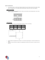
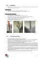
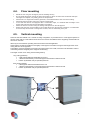
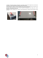
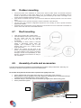
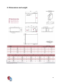
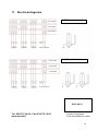
INSTALLATION AND MAINTENANCE MANUAL MINI AIR HANDLING UNIT « MISTRAL » 1 1. Presentation 2. Generalities 2.1. Warnings Generalities 2.3. Safety instructions 3. Reception - Storage Installation 4.1. The choice of the place Handling Ceiling mounting Floor mounting Wall mounting Outdoor mounting Roof mounting 4.8. Units and accesories assembly 5. Hydraulic connection 5.1. Coils connection 5.2. Evacuation of condensates 5.3. Control valves 6. Air duct connection 7. Electrical connection 7.1. Identification plate 7.2. Fans 7.3. Electric batteries 8. Dimensions and weight 9. Maintenance 10. User guide 11. Electrical diagrams 3 3 4 4 4 4.5. 9 10 10 Erreur ! Signet non défini. 11 14 18 20 2 1. Presentation Mistral is a compact air handling unit for heating and cooling applications essentially on pipework system with water coils and/or electric batteries supply. Mainly used in ceiling mounting, it offers the advantages of a compact ceiled device associated to the modularity of classic air handling units. Standard units are made with a double-skin casing in steel with 1 mm of thickness + 25 mm of insulation classified M0. Those units also exist in a dual flow configuration. To the main casing (fan section + coil section) it could be added, before and after, some optional accessories like: Sleeves Mixing box 2 or 3 ways Filter casing with pocket filter Additional electric battery casing Sound attenuating chamber (blowing and/or return) Plenum with spigots Heat recovery exchanger casing Some constructive options are proposed: Lacquer-coated RAL 9003 Super insulation acoustic TSR (Technic of spread sound). The range is composed of 3 sizes and 5 models. The ventilation is provided by a power set of free wheel + motor (M20 to M60 model). The speed variation is got by the use of a frequency converter (M30 to M60 model). 2. Generalities 2.1. Warnings Read carefully this manual before starting the installation. Confide the installation to a qualified installer. The units must be installed and bring into service respecting all instructions giving in this manual and in compliance with local regulations. The installer will have to establish a declaration of conformity and mark the installation. Check that the tension and the frequency of the power supply is like the ones necessary at the unit which has to be installed. Eventually, take into account of others devices connected up at the same electric circuit. Also make sure that the safety requirements of national standards have been respected over the power supply circuit and in particular that you dispose of a connection on the floor with an adequate size. After the installation, make a complete test of the system and explain all the functions to the user. It is recommended to disinfect once by year, condensate drain pan to avoid the development and spreading of legionella. Use this unit only as a part of registered applications. Keep the device away from frost. Before any intervention on the system and before handling any intern components cut the power to the main circuit-breaker. The manufacturer declines any responsibility for damage caused by the modification or mistake in electric connections or hydraulic connections. Failing to follow the manufacturer instructions concerning the installation or the use of the unit in conditions that exceed functioning limits indicated in this manual can lead to the loss of the unit warranty. Failing to follow the electrics security rules can caused a risk of fire in the case of an electric short. In case of an unusual functioning, turn off the unit, remove the electricity supply and contact specialized personnel. Maintenance must be made only by qualified personnel. Recycle packaging in accordance with local laws regarding waste. 3 2.2. Generalities It should be avoiding the use of mini AHU in an atmosphere that contains oil vapors, sea air, corrosive or dusty air. Unless particular conditions, the manufacturer gives one year parts warranty against defects in conception or production. Are excluded defects of installation and use and also wearing parts and environment condition which damage the smooth functioning of the device that would not be specified in the order. The units should be mounted and bring into service following the instructions giving in this manual in compliance with local regulations. The installer will have to establish a declaration of conformity and mark the installation. 2.3. Safety instructions Installation works and start-up should be made by qualified personnel. Before any intervention: Disconnect the power supply All mobile parts (motors, fans, dampers, etc…) must be turn off. Wait the drop of temperature of hot parts (heat exchanger, electric batteries, motors, etc…) Wait pressure balance in unit boxes. During the intervention or start-up, never exceed the operating range of the unit. 3. Reception - Storage Ensure that the unit has not been damaged during the transport. If it is the case, it must be done reserves over the delivery coupon of the transporter and confirm to him by registered letter over 48 hours. Does neither install nor use damaged devices. Check the conformity of goods delivered in relation to the order. Read and control the instructions over the identification plate. The device must be delivered in a pallet over shrink packaging. Additional casings and accessories could be packaged in the same pallet or individually Storage the equipment in a clean, dry place, protected from shocks, vibration and temperature fluctuation and at a relative humidity level of less than 90%. The period of storage should not exceed 1 year. Proceed with the unpacking of the device using the protections of accident prevention which are required. 4. Installation 4.1. The choice of the place Avoid the following locations: Areas close by sources of heat. Humid locations and places where water may penetrate into the unit. Location advised: Consider a location where the installation will be easier. Allow required clearances. It could be easy to connect condensate drain pipe to the appropriated pipework. 4 Space for maintenance In the chosen location, check that the clearances (lateral or by the bottom) around the unit offer enough space for maintenance. If it is needed, make a test by taking out the coils, motors, fans and filters. Clearance by the bottom The filters could be removed laterally (from 2 sides) or by the bottom of the standard device. In this case, foresee a clearance of 338 mm. Lateral clearance Space available in order to can clear laterally the filters, the coils, or the fan(s). MISTRAL M20-M30 M40-M50 M60 A 926 1376 1826 B 975 1425 1885 (Space for maintenance) All the hydraulic arrangements are situated on one same face (following the connection indicated in the order) Foresee an access from the two sides for the Mistral M60 model to the fan section in order to access to each fan. 5 4.2. Handling Depending on the unit configuration at the delivery, the handling is carried out by support frame or suspension fixation, or by delivery pallet. Pallet configuration Use forks enough long that can pass under the depth of the pallet. The center of gravity and the load distribution have to be taking into account. Rail support/ Hangers configuration Only use adapted and authorized lift system. Fasten the lift system to the extremity of the rail support or to hangers Be careful to the center of gravity during the lifting to avoid sliding or tipping of the load. The angle formed by the lifting cable and the load do not be inferior to 45° Move the unit with precaution and avoid abrupt movements The device doesn’t be fitted brutally or suffer shocks. No additional load can be lifting with the unit. 4.3. Ceiling mounting Use a forklift to facilitate the installation of the unit to the ceiling. Do not handle the device using at the same times pipes or valves as well as the condensate drain pan. The edges are sharped; carry safety gloves for this operation Check there is no fragments inside the pipework; it could deteriorate the mini AHU at the starting. Check also that the surface using as a support (ceiling, wall, floor...) is perfectly flat. Raise the unit carefully, holding it by its suspension edges. Fasten the mounting clips (not supplied) with a diameter maximum of 8 mm in the ceiling regarding the gap of fixation clips (clips are realized with slotted holes to permit a final adjusting). To achieve this, it is recommended to use a template. The mounting clips and its anchoring system must be adapted to the nature of the support and all of those have to support the weight of the unit. Introduce the mounting clips in the fixing holes, add anti vibration rubber / washers / nuts et counternuts (accessories not supplied) without tighten Put up the unit horizontally with a spirit level adjusting the nuts and counternuts of threaded mounting clips. Then, create a slight slope of minimum 2% toward the output of the condensate drain pan in order to make easier the runoff (Mistral M20 and M30 slope of 5 mm, Mistral M40 and M50, slope of 7 mm, Mistral M60 slope of 10 mm) Ensure that when the unit is installed, it has a slight slope (2%) favoring the evacuation of condensates. A reverse slope would result of a stagnation of water, even an overflowing of the pan. 6 4.4. Floor mounting Handle the unit using the rail support (see the handling section) Do not handle the device using at the same times pipes or valves as well as the condensate drain pan. The edges are sharped; carry safety gloves for this operation. Check there is no fragments inside the pipework; it could deteriorate the mini AHU at the starting. Check also that the surface using as a support is perfectly flat. In the case that devices are equipped with a condensate output, it is essential that the height of the support match at least with the required height of the siphon. Secure the device to the floor using the oblong holes present on the rail supports. Ensure that when the unit is installed, it has a slight slope (2%) favoring the evacuation of condensates. A reverse slope would result of a stagnation of water, even an overflowing of the pan. 4.5. Vertical mounting When the mini AHU Mistral is in a vertical mounting configuration, is provided with 2 or 3 rail supports (based on the size of the casing). Those fixations must have to be used for the fulfillment of the supporting and the fixation of the units on the wall. All the layout of the Mistral’s operating instructions manual remains applicable. Check that the mechanical resistance and rigidity of the support or the wall is enough for the weight of the unit or casing that have to be supported. The fixations used (no supplied) for anchoring the support frame on the wall, must have to be selected in order to could taking back the integrality of the weight of the device(s). The weight of each unit or casing must be taking back by: Long casing (1050mm) 3 frail supports delivered assembled on the unit 1 fixation at the extremity of each rail support which means 6 fixations in total. Fixation by threaded rods (or equivalent) M8 mini Short casing (525mm) 2 rail supports delivered assembled on the unit 1 fixation at the extremity of each rail support which means 4 fixations in total. Fixation by threaded rods (or equivalent) M8 mini 7 In addition to the fixation system by rail support, it is necessary to take over the weight of the unit on the front of the device, using riveted brackets mounting provided for that purpose. The brackets permit a fixation by threaded rods (M8 o M10). The rods will be hanged or put on the floor to be used as a support (in all cases, ensure to maintain the accessibility to the filters). The fitting of the brackets will be made in order to obtain the horizontality of each casing and a correct alignment of casings among each other. In the case there are multiples units or casings, it will be imperatively to make the previous operation casing by casing. 8 4.6. Choose the place of the installation in order that the fresh air intake doesn’t be oriented toward the direction of the wind. In areas where there is a lot of snowfall, the place of the installation must be chosen in order that the snow doesn’t damage the good functioning of the device. The height of the support must be adapted following those data. If the device is mounted on the roof, you must ensure before the allowed pressure of the roof and the frame. The installation on the ground must permit a correct evacuation of the rainwater The use of the unit in outdoor configuration requires the roof mounting in order to protect the device against bad weathers. All panels which composed the roof are delivered not mounted but as a kit of elements to assemble on the box of the main unit and on the additional boxes. 4.7. Outdoor mounting Roof mounting Take off the protective film of sheet metals. Install the different sheet metals of the roof over the unit. Check that the roof overflows sufficiently the cover of the unit and the accessories. The assembly of sheet metals is executed thanks to self-tapping screws which are supplied, with a maximum gap of 15cm between each screw. Put a sealing washer under each screw. Staunch the covering and the bond of the panels. An insufficient impermeability can lead to a water infiltration in the unit and consecutive damages. Ensure the impermeability of each element, especially at the entrance of wiring or coil connections. 4.8. Assembly of units and accessories The units and accessories are destined to be assembled by the interior at the junction frame. That’s why it is necessary to dismount some panels to access to the fixation points. Do not take off all panels at the same time, to preserve the rigidity of the unit. Put the adhesive seal on the casing of the main unit or on the casing of the accessory. Bring casings as much as possible to each other. Before the assembly (do not use the heat exchanger connectors or the condensate drains to push or pull the units). Assemble casings to each other thanks to the fastenings supplied at the different fixing points. Put the panels back together Seal Fixation points 9 5. Hydraulic connection 5.1. Coils connection Size M20-M30 M40-M50 M60 2- Row Coil Male 15 x 21 Male 20 x 27 Male 20 x 27 4- Row Coil Male 20 x 27 Male 26 x 34 Male 26 x 34 6- Row Coil Male 26 x 34 Male 33 x 42 Male 33 x 42 Operating limits: Maximum allowable pressure: 8 bar Minimum ambient air temperature: 5°C, maximum: 32°C Minimum water temperature: 2°C, maximum 100°C Maximum supply air temperature: 45°C Ensure that the hydraulic network is well done (dimensioning, solidity, total clean-up, drain, etc…) The functioning of auxiliary electrical resistances is forbidden when the main coil is supplied with hot water. Unless otherwise indicated concerning the machine, with an arrangement on the left, the inlet of water matches the pipe at the bottom (for ceiling mounted unit). The outlet of water matches the pipe at the top. With an arrangement on the right, the configuration is reversed: water inlet on the top of the pipe and water outlet on the bottom of the pipe. For a 4 tubes installation (device equipped of 2 coils), the chilled water coil is located before the hot water coil in the direction of the air (unless otherwise specified) The torque applied to use for the hydraulic connection is 25Nm. The tightening on the inlet and outlet connections of coils has to be ensured with precaution with a backup wrench to avoid the transfer of the effort on the coil’s tubes. Install purges in the higher parts of the installation. Purge entirely the air inside the coil when the water is passing on. It is also recommended to install ball valves on the water inlet and outlet, in order to could dismount the units without draining the complete installation. Foresee drain plugs of the unit and the circuit at the lower point. It is imperative to foresee a non-freeze security for the devices that used with introduction of fresh air, in order to protect efficiently the coil if the hot water production is stopped. It is recommended to do the piping connection with isolated flexible pipes. For a connection that used with steel tubes, ensure it are aligned and suspended to not put mechanical stress on the unit. When the connection is done, it is necessary to surround the valves and the pipes with impermeable and insulating materials. Insulate correctly the pipelines. Check that all connector seals when the system is filling of water. The manufacturer cannot guarantee the quality of the seals which are provided by the installer. AIRCALO decline all responsibility of an eventual malfunction of the kit and for damages that can come from leaks. 5.2. Evacuation of condensates The condensate drain pan is equipped with a smooth output DN 14 mm. It is recommended to connect the pipe PVC of 25 mm with sealed links and to surround all of this with an adequate insulating cover. To ensure a good run off of the condensates, the pipe should be slopped downwards and have a constant downslope of 2 % without curves or horizontal draining. Its connection to the sewage system has to be done with a siphon correctly proportioned to permit an enough and permanent evacuation of water. 10 Foresee necessarily a vertical siphon such as : L1 (mm) will be equal to 2 x the pressure / depression of the unit (mmCE) Mistral L1 Recommended L2 Recommended M20-M30 80 mm 40 mm M40-M50 100 mm 50 mm M60 100 mm 50 mm In case of multiple units, the evacuation plan to realized is this one : If it is not possible to ensure this downslope to drain the condensates, it will be necessary to install an auxiliary draining pump with a level controller (we advise the models with floats to stop the flow in case of pump damage). The flow of the pump to foresee will be in function of hygrometry rate. Foresee to stop the chilled water production in case of power cut. Before the starting of the unit, pour some water in the extern condensate drain pan. Check the regular runoff of the contents of the pan and control that the pump evacuates the water in the case of a mounting with condensate pump. If the runoff is insufficient, check the slope of the unit and the pipework and look for an eventual bottleneck. 5.3. Control valves The motor control valves mounting can be supply by us. In this case, they are mounted in the factory. The standard motors of the valves are planned to be supplied with 230V, their average consumption 5 VA. The valves are type 2 ways or 3 ways with by-pass. The valves must close the water inlet when there is no electricity supply. Before looking at the connections, control the position of the thermo-electric valve: normally closed from battery side and normally opened from the by-pass side. When the ambient temperature do not satisfy the thermostat, an electric resistance cause the warming of thermostatic heating element that determine the slope of the piston ; the valve opens progressively to circulate the water inside the coil. When the ambient temperature reaches the level required by the thermostat when the electricity supply is cut, the valve is closed progressively from the coil side and opened from the by-pass side. Insulate with precaution the pipes, the all valve, the coil connections (chiller water side) to avoid that the condensation that could be formed, do not flow in the false ceiling. It is recommended to foresee the control valve as in the case of non-functioning of the ventilation the valve won’t be opened. 6. Air duct connection It is recommended to use ducts with galvanized steel covered with heating insulation to avoid the eventual formation of condensates and to avoid losses. Connect ducts with sleeves which absorb the vibration and reduce noise propagation. Ensure to cover the totality of the surface of framing angles to ensure the maximum impermeability. Following the installation requirement, you should foresee a sound attenuating chamber. The pressure losses generated by the ductwork must be compatible with the performance of mini AHU. A study of pressure losses of the ductwork has to be done by a professional. Otherwise, it should be checked that the ducts are smooth and that do not have any leaks or crushing or obstructions. The bends generate huge pressure losses and even if its bend radius is small. 11 Performance curves of the main casing (without pressure losses of components and networks) M20 Air Flow (m³/h) Pressure losses (Pa) Total static pressure (Pa) Minimum air flow authorized Filter G3M 2- Row Coil Filter G4 4- Row Coil Filter F7 pocket 6- Row Coil Filter F7 pleated Moisture collector Filter F9 pocket M30 Maximum air flow authorized for heating Air Flow (m³/h) Pressure losses (Pa) Total pressure (Pa) Maximum air flow authorized for cooling Filter G3M 2- Row Coil Filter G4 4- Row Coil Filter F7 pocket 6- Row Coil Filter F7 pleated Moisture collector Filter F9 pocket 12 M40 Air Flow (m³/h) Pressure losses (Pa) Total pressure (Pa) Maximum air flow authorized for cooling Filter G3M 2- Row Coil Filter G4 4- Row Coil Filter F7 pocket 6- Row Coil Filter F7 pleated Moisture collector Filter F9 pocket M50 Maximum air flow authorized for heating Air Flow (m³/h) Pressure losses (Pa) Total pressure (Pa) Maximum air flow authorized for cooling Filter G3M 2- Row Coil Filter G4 4- Row Coil Filter F7 pocket 6- Row Coil Filter F7 pleated Moisture collector Filter F9 pocket 13 M60 Maximum air flow authorized for heating Air Flow (m³/h) Pressure losses (Pa) Total pressure (Pa) Maximum air flow authorized for cooling Filter G3M 2- Row Coil Filter G4 4- Row Coil Filter F7 pocket 6- Row Coil Filter F7 pleated Moisture collector Filter F9 pocket 7. Electrical connection The electrical installation of the device must be conformed to installation rules in the country of destination and be realized by qualified personnel following the diagrams added at the end of the manual. Make the ground connection before any other connection. Check that the power supply pass by the circuit-breaker that could cut the current in all pole, respecting a gap of at least 3 mm between the contacts. The connecting wires section must be defined according to the power absorbed given below and the cable lengths to fit following the geometry of the location. 7.1. Identification plate Each AHU is identified by a serial number. This identification number is on the identification plate located on the AHU. This label indicates: The size of the unit The power and the polarity of the electric motors of fans The frequency range of the use, in the case of a use with a frequency converter The tension, the number of phase, the frequency of the electricity supply. 14 7.2. Fans Fans are pre-wired in the factory in order to facilitate the electrical connection. The installer would have to ensure that the connection, the protection and the motor controller are done following the electric standards. Fans number depends on the selected unit model. Each fan is composed of a reaction turbine directly driven by a three-phase asynchronous motor. The electric motor has a thermal protection type PTO. The rated power of the electric motor depends on the operating ranging needed (cf. selection software) The motor is wired in delta connection 230V/3/50Hz, in order to can be used with a frequency converter (230V single power supply, output 230V / 3 / 50Hz) Thanks the modulation of the rotation frequency, the frequency converter calodrive (in option) permits to adapt the speed of the fan depending on the working point(s) wanted. In the case of a use with another type of converter, it could be necessary to modify the wiring of the motor. Operating limits: Minimum allowable frequency: 20Hz Maximum allowable frequency: depend on the motor type and selected power. Refer to the identification plate of the unit and to the technical specification sheet to get more information. Never operate the fan outside of its frequency range or with a higher power level than the power rating of the motor. 15 The fan can be accessed by the lateral panel of the fan. It is composed of 1 cable gland for the passing of the power supply cable and 1 cable gland for the PTO cable. Cable gland of the motor Due to the use of a frequency converter, it is necessary to realize the connection, between the converter and the motors, as short as possible and with a shielded cable in order to avoid electromagnetic disturbances. Check the lack of disturbance. Electric motors are equipped with thermal protections type PTO which will have to be connected to the control system to ensure the protection against the overheating. Also refer to the frequency converter manual (in option) for the electrical connection rules and electric diagrams propositions. Adjustment of the shell of the fan Due to the transport and the handling, the shell could be decentered in relation to the free wheel of the fan. Before the first starting up of the unit (not supplied by electricity), you can make a first control which will be to turn the free wheel with the hand in order to check if there is no rubbing. You could complete this test by checking the play of the height and the width of both sides of the wheel. If it is decentered, it is necessary to recenter the shell. It means it is necessary to disunite the fan from the inside panel of dividing wall to take out the unit. Fixation screws of the fan support When the unit it is taking out, unscrew the fixation screw of the shell and proceed to its alignment with the turbine of the fan. Make the same reverse process for the reassembly. Fixation screw of the shell 16 7.3. Electric batteries Battery When the device is supplied with electrical resistances, a connection box is mounted on the hydraulic arrangement side. It is composed of a manually reset safety thermostat. In standard, the thermostat is adjusted to be activated for 105°C. If the thermostat is activated, you should cut the general power supply. The reset of the thermostat is done at the box without disunite the panel. Check that the ventilation system works correctly (enough air flow) before to restart the thermostat. Post-ventilation: When the electric battery is stopped, it is necessary to foresee a forced operating temporization of fan(s) in order to ensure a dissipation of the residual energy. For capacity < 9 kW the minimal temporization is of 4 minutes For capacity > 9 kW the minimal temporization is of 5 minutes The non-observation of this enslavement could deteriorate the unit even the environment. During the functioning of the electric battery, a cut of electricity network supply can cause the onset of the security thermostat. 17 8. Dimensions and weight Vertical and horizontal mounting Lateral panel motor access Inferior panel filter access Lateral panel coils access Lateral panel filter access Dimensions non contractual. Subject to change. 18 9. Maintenance Cleaning operations and the maintenance must be done by specialized personnel. Turn off the electrical supply. Filters The cleaning of the filters depends on the functioning of the unit (about every two months). They have to be changed at least once a year. Only operate the unit with the filter. Long stoppage period Before restarting the unit and at least once a year: Clean or change the filters of the unit Examine the fins of the coil and if it is necessary, remove the dust Examine and clean the condensate drain pan of the unit and remove any stranger elements. Check that the electrical connections are duly tightened. Additional maintenance Water coils even the condensate drain pan are mounted on ways that permit an easy lateral disassembly. In this case, take off the different lateral panels. The clean state is a determining factor for a good yield of the unit. The cleaning of the coil can be done with a vacuum cleaner and/or a jet of compressed air. The replacement of the motorized fan is done laterally. 10. User guide Once the installation and test are finished, explain to the user the main instructions of the functioning and maintenance manual, and especially pay attention of the main operating modes of the unit: How to put into service and stop How to modify the operating modes How to select the temperature Give to the user the installation manual of the unit, as well as the use and service manual, in that way, it could be used for the maintenance or in the case of an installation in another place or other eventualities. 19 11. Electrical diagrams 3-STAGES TERMINAL MISTRAL M20-M30-M40 2-STAGES TERMINAL 1-STAGE TERMINAL SECURITY THERMOSTAT 3-STAGES TERMINAL FAN MISTRAL M50-M60 2-STAGES TERMINAL 1-STAGE TERMINAL SECURITY THERMOSTAT FAN 1 FAN 2 M 19-04-13 Tel: 05 56 70 14 00 - Fax 05 56 70 14 09 www.aircalo.fr 14 Avenue Cassiopée 33160 Saint Médard en Jalles 20