1
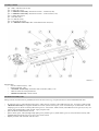
Assembly contents
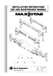
pos. 1 and 2: side drive unit (2 No)
pos. 3: centre bar (1 No)
pos. 4: <Manual Version only> hollow box section – extention (2 No)
pos. 5: <Manual Version only> hollow box section – centre section (1 No)
pos. 6: clamp plate (2 No)
pos. 7: bracket (2 No)
pos. 8: U-bolt kit (2 No)
pos. 9: stop block kit (2 No)
pos. 10: <Manual Version only> Hex screw M8x35 with nut (2 No)
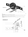
Scheme 2
Supplied also:
– caravan control unit (CC): 1 No
– remote controller: 1 No
– <Automatic Version only> automatic roller controller (ARC): 1 No
–
cable set/connectors/crimps/cable ties
– <Manual Version only> 19mm wrench
Mechanical assembly order
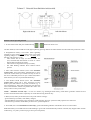
Fitting in front of caravan axle is preferable, however in some cases (e.g. no space) the mover can be fitted behind the axle.
–
–
–
–
–
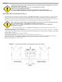
fit centre bar (pos. 3) into both drive units (pos.1 and 2). Screw in loosely 4 No of M10 screws (pos. 14) with a 17mm wrench.
<Manual Version only> Fit together hollow box section (centre section pos.5, 2 No of extention pos. 4) and slide it onto side
couplings (pos.12). Screw in loosely M6 screws (pos.13; 4 No) with a 10mm wrench, insert M8x35 screws (pos.10; 2 No), use
nylock nuts supplied and a 13mm wrench. Apply torque 27 Nm.
place the Mover underneath the caravan
place U-bolts (pos.8; 2 No) through clamp plate (pos.6), bracket (pos.7), thick washer (pos.15; 4 No) and secure loosely with
supplied M10 nylock nuts (pos.16; 4 No). Use a 17mm wrench.
Repeat procedure with the other side drive unit