1
User’s Manual
(For SI/ engineer)
Powerline/Cable
200M Bridge
1. Cable / Powerline Networking Installation
1.1 Simple step to install cable Networking
2
1.2 Simple step to install Powerline Networking
3
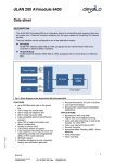
1.3 Application Block Diagram
1.3.1 Internet ADSL with one computer via power outlet
(Bridge mode: Switch in PL/Cable side)
1.3.2 Online game via power outlet (Bridge mode: Switch in PL/Cable side)
4
1.3.3 Internet ADSL and Home Networking via power outlet
(Bridge mode: Switch in PL/Cable side)
5
1.3.4 Internet ADSL and Home Networking via coaxial cable
(Master/Slave mode: Switch in Cable only)
In this case, the home Powerline device need to change the Private Network Name to avoid the interference from
Cable device, due to the default settings is the same. Or change the Powerline/cable 200M bridge private network
name to another name can work well too.
6
7
1.4 Benefits
‧Data transfers at up to 200 Mbps over the household power circuit or coaxial cable
‧Ranges of 200 meters
‧No need new wires for Home networking
‧Deliver the benefits of Ethernet without the wiring expense
‧Send even large files between PCs without long waits
‧High-speed Internet and DVD-quality video streaming
‧Fully compliant with IEEE 802.3, IEEE 802.3u
‧Privacy through DES encryption
1.5 Features
‧Use the home's existing Powerline or coaxial cable
‧Support coexist with Powerline 85M or 14M bridges
‧Easy to install
‧Throughout the whole house, just use your power circuit to access the Internet or PC network
‧Orthogonal Frequency Division Multiplexing for high data reliability in noisy media conditions
‧Integrated Enhanced Quality of Service(QoS) features: Eight levels of prioritized random access, contention
free access, and segment bursting
‧Up to 200Mbps data rate on Powerline or coaxial cable
‧Provide 128-bit AES Link Encryption with key management for secure Powerline communications
‧Master/Slave mode support (coaxial cable link only)
‧Up to 252 slaves with 1 master, 253 total devices for cable link
‧Up to 4 masters with up to 1008 slaves, 1012 total devices in 4 AVLNs for cable link
‧Up to 4096 addressable devices including bridged devices
1.6 Package Contents
‧Powerline/Cable 200M Ethernet Bridge unit
‧Utility & Manual CD
‧Quick Installation Guide
‧Category 5 cable
8
1.7 The Front LEDs
LED
State
ON
Powerline network activity.
OFF
Search or no Powerline network activity.
ON
Ethernet connection is OK.
LINK
ETH
Description
Flashing Data transfer.
POWER
OFF
No link to Ethernet.
ON
Power on.
OFF
Powerline off or failure.
1.8 The Rear Ports
Connector
POWER
Description
Connect to power cord.
Connect to coaxial cable. Be sure, in some countries or Europe, the coaxial connector is
Coaxial Cable
different so user need to buy extra converter to link the device to the internal TV cable not
the satellite cable.
Switch to cable only mode or Powerline/Cable mode, when switch to cable only, the
switch
Powerline function will be disable. When switch to Powerline/cable, it can enable both, so
just don’t connect to the coaxial cable, it can use as Powerline device.
LAN
Secure
Router is successfully connected to a device through the corresponding port.
If the LED is flashing, the Router is actively sending or receiving data over that port.
Button can auto secure and group the Powerline devices.
9
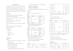
※ The Europe TV connector is different type, like the picture 1.8.1. So user need to have the converter(picture 1.8.2) to
connect the coaxial cable to the TV cable connector on the wall, don’t connect the device to the satellite connector, it
will not work.
In some countries or in Europe use
different TV connector for coaxial cable.
Picture 1.8.1
Use this converter to connect to the
coaxial cable and then connect to
the TV connector on the wall.
Picture 1.8.2
10
1.9 The Bottom Port
Button
Reset
Description
Push this button can reset to the factory default settings.
1.10 System Requirements
‧Ethernet device
‧AC power outlet
‧Cable link
‧Windows system for encryption setup
11
I N T E L L O N
H O M E P L U G
A V
D M
U S E R ’ S
G U I D E
3. Device Manager Use
3.1.
Device Manager Installation
The following describes the installation of the Device Manager software.
1.
2.
3.
4.
5.
6.
7.
8.
9.
A network card must be installed and enabled before continuing.
Locate the Device Manager Software folder on the Intellon Customer FTP site.
Download and unzip the DM software.
Note the following files:
x DeviceManagerSetup.msi
x Setup.exe
x Setup.ini
If the Windows Installer is already installed, simply run the .msi file. It will invoke the Windows Installer wizard to
walk the user through a few simple steps to install the Device Manager. By default, an Intellon directory under
Program Files, will be created to hold the required files for operation. The driver files will automatically be installed
in the system32 directory. A Device Manager (DM) icon will appear on the desktop as a shortcut for launching the
application.
If the Windows Installer is not already installed, simply run Setup.exe, which will install the Windows Installer first
and then proceed with the Device Manager installation.
To use the installer with a previously installed Device Manager will require removing the pre-existing Device
Manager through the “Add or Remove Programs” facility with Windows. Files in the repository directory can be
moved to backup directories to manage multiple versions.
Launch the Device Manager. If it fails to launch, the probable cause is that .NET 1.1 redistributable is not
installed. .NET Framework 1.1 Redistributable is freely downloadable from:
http://www.microsoft.com/downloads/results.aspx?pocId=&freetext=.NET+redistributable&DisplayLang=en.
The installation is now complete.
INTELLON CONFIDENTIAL
6
25004106 Revision 1
I N T E L L O N
3.2.
H O M E P L U G
A V
D M
U S E R ’ S
G U I D E
Common Features of Tabbed Windows
3.2.1.
Icon Tool Bar
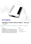
The Device Manager graphical user interface is shown in Figure 3. Note that the tool bar has icons to visually indicate the
operation performed. A textual Tool Tip function has been added to supplement the graphical indication with a textual
description of a tool buttons’ functionality. The tool tip function is invoked by “hovering” the mouse over a specific tool bar
button for a few moments.
The Tool Bar is visible and operational from all functional tabs; this makes device operations such as reading or writing a
PIB much easier since the operator is no longer required to return to the Configuration Tab to execute tool bar operations.
Figure 3: The Device Manager Default User Interface
INTELLON CONFIDENTIAL
7
25004106 Revision 1
I N T E L L O N
H O M E P L U G
A V
D M
U S E R ’ S
G U I D E
3.2.2.
NIC Selector
As demonstrated in Figure 4, a second tool bar is provided for selection of Network Interface Cards and connected
devices. The name of the network cards as displayed in the network interface drop-down list has been changed to
indicate the Windows “Friendly Name” of the adapter. This makes it much easier to select the appropriate network adapter
when several NIC are present.
Figure 4: Viewing and Selecting a Network Interface Card
INTELLON CONFIDENTIAL
8
25004106 Revision 1
I N T E L L O N
H O M E P L U G
A V
D M
U S E R ’ S
G U I D E
Figure 5: Selecting Viewable Tabs
Functional Tabs can be selectively enabled or disable by checking or un-checking the Tab name on the “View” Drop
Down Menu.
INTELLON CONFIDENTIAL
9
25004106 Revision 1
I N T E L L O N
H O M E P L U G
A V
D M
U S E R ’ S
G U I D E
3.2.3.
Drop-down Menus
The Device Manager’s drop-down menus are just above the icon bar and open as illustrated in Figure 5 and Figure 6.
3.2.3.1.
“View” Drop-down Menu
The “View” drop-down menu enables selective hiding of functional tabs from view. This simplifies the visual layout and
reduces key strokes required by eliminating unused tab(s) from view.
3.2.3.2.
Device Drop-down Menu
The Device Drop-down Menu provides an alternate method for accessing Device Operations such as reading a PIB,
writing a PIB, Loading Firmware, or resetting a device.
3.2.3.3.
“Help” Drop-down Menu
From the Help menu, a user can access the “About” sub-menu which displays a dialog indicating the Product Name and
version.
Figure 6: The File Menu
3.2.4.
Status Bar
The Application Status Bar displays read-only device information relating to the session.
INTELLON CONFIDENTIAL
10
25004106 Revision 1
I N T E L L O N
3.3.
H O M E P L U G
A V
D M
U S E R ’ S
G U I D E
Configuration Tab (Configuration Window)
Figure 7: Configuration Tab Window
3.3.1.
Configuration Fields
The DM GUI tabbed window labeled ‘Configuration’ is shown in Figure 7. Areas available for configuration using this
window include:
x File Selection: Softloader and Prescaler files
x Personalization Information
o MAC Address, Network Password, User HFID, MDU Configuration
x Configuration Check Boxes
x Connected Device Identification
Fields provided on this window, in the areas listed above, allow updating or changing of PIB variables values. These
changes are made to the locally stored (the PIB image in the DM’s memory) PIB and are not loaded to the NVRAM until
the Write PIB Function is selected.
Note: The DM and the firmware contain code that interprets the values of the PIB. See below. This shared PIB
management code has a version number, as does the firmware file, and the firmware (SW version). The version codes
must match for update (Write) to occur successfully.
INTELLON CONFIDENTIAL
11
25004106 Revision 1
I N T E L L O N
H O M E P L U G
A V
D M
U S E R ’ S
G U I D E
To upgrade a remote device, both the PIB and the MAC firmware should be updated at the same time. It is very
important to follow this step as failure to do so will result in the device being forced into an isolated network.
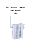
Firmware File Name: INT6000-v3.3.4-0-8-A.nvm
v1.4.2 -4-A.nvm
SDRAM Configuration Code
PIB Version Code
Firmware Version
-A
Version String: INT6000MAC-1MAC-3-3-3348-00-2764-2008-0808-FINAL-A
SDRAM Configuration Code
Major Firmware Version
Build Date
Build Number
PIB Version Code
Eng Update Version
Figure 8: Firmware and Version Strings
To enable download of the PIB to a device, the DM will compare the connected device’s SW version information to those
compatible with the DM’s version of the PIB management code. Valid combinations will allow the Write functionality to
download and commit the PIB to NVRAM. Invalid combinations will be reported to the user upon pressing the Write
button, and the write operation will be cancelled.
3.3.2.
File Selection
Browse buttons are used to locate the Softloader and Prescaler files. The Write SFLD button is used to write the
softloader file to the device. These buttons initiate standard browse windows.
3.3.3.
Personalization Information
The Personalization Information area of the Configuration Tab window allows the configuration of: MAC Address, Network
Password, User HFID, MDU Master or Slave and Auto upgrade or not.
The ‘User HFID’ text box allows the user to create and manage a Human Friendly Identifier (HFID) of up to 64 characters.
The MDU Configuration is used to enable and specify the special MDU functionality. Checking the “Enable MDU”
checkbox, will expose the ‘Master’ and ‘Slave’ radio buttons, providing a toggle choice. This enables the user to configure
the CCo as a Master and all STAs as slaves, which means that the Slaves can no longer communicate with each other –
they can only communicate with the Master. This function must be deliberately enabled by checking the Enable MDU
box.
3.3.3.1.
Managing MAC Addresses
The MAC Address is a writable entity. To write it, you must be working with a PIB that matches the DM’s version of the
PIB. The upgrade process will preserve the running MAC address, so modifying the address is generally not needed.
Running in a flash-less environment is an exception. When prompted for the PIB with the ‘Bootloader’ a non-default MAC
address must be accessible. The address is accomplished with either a non-default MAC address in the selected PIB, or
a non-default MAC address in the exposed MAC address field.
Downloading firmware now requires an accompanying PIB.
WARNING: If new firmware encounters an unacceptable PIB upon coming out of reset, the MAC Address
status bar will display (00:b0:52:00:00:03). This creates an unrecoverable scenario.
NOTE: The recommended procedure for upgrading firmware is to use the Load FW button. This procedure will
automatically first read the running PIB and save the existing MAC address. The user will be prompted for a selection of
PIB and firmware which will be down loaded to the device including the correct MAC address. Status of the transfer and
commit stages of the procedure are provided in the status bar on the lower right of the form.
INTELLON CONFIDENTIAL
12
25004106 Revision 1
I N T E L L O N
3.3.4.
H O M E P L U G
A V
D M
U S E R ’ S
G U I D E
Configuration Checkboxes
3.3.4.1.
Force Commit
The user should check this box when they want to force writing the firmware and or PIB to flash in the scenario where the
firmware was started from the Bootloader or Softloader.
3.3.4.2.
Disable Host Action checkbox
This provides the user with the option to disable the DM’s responsive functionality with respect to the Host Action
Indications received from the Bootloader or Softloader. See following description of the Host Action Indication behavior.
Host Action Indication Functionality
The Host Action Indication functionality is associated with an unsolicited Host Action MME which is sent to the host from
the FW. When the Disable Host Action checkbox is not selected, the Device Manager will react to the reception of these
messages.
* In a flash-less environment, the ROM-based Bootloader will respond to the Device Manager’s discovery process. The
Device Manager will form a connection with the device evidenced with the default MAC address (00:b0:52:00:00:01)
and the appearance of Bootloader in the version string textbox found at the bottom middle of the form.
The Bootloader will periodically send Host Action Indications to the Device Manager based on its state. Initially, the
Bootloader will ask for SDRAM configuration. Based on the user’s selection of the SDRAM size, which is chosen with the
new SDRAM Size drop-down, one of two SDRAM configuration files will be downloaded to the Bootloader. This will
happen automatically, evidenced by “SDRAM Config updated” message in the bottom right status box. The two
configuration files, each associated with 16M or 64M SDRAM sizes are provided by Intellon and are part of the Device
Manager installation package. They are co-located with the bundle of Device Manager files placed in the location chosen
during installation. If these files are lost, removed, or otherwise not found in the native directory, a browse window will pop
up to for the user to select the desired file.
Subsequent to downloading SDRAM configuration, the Bootloader will request loader information. A browse window for
the PIB will first appear. The selected PIB will undergo some validation and be downloaded to the device, evidenced with
a PIB update successful status message.
WARNING: selection of a PIB containing a default MAC address (00:b0:52:00:00:01), will be invalidated
and abort the existing session. A new session will be invoked with the reception of a subsequent Host
Action request for loader information as part of the periodic behavior.
The Device Manager will next prompt the user with a browse window to select firmware. The selected firmware file will be
downloaded as evidenced with a “Downloading firmware” status message and subsequent “Update firmware successful”
status message, if successful.
The new firmware will be started, the PIB installed and the version string text box should indicate that the firmware is
running with the MAC address provided in the PIB.
Downloading a new PIB or firmware image to the running firmware will stimulate a Host Action request to read one or both
modules. In general, the host makes no assumptions regarding the source of the updates, even if the source is itself. The
Device Manager will read the PIB and or firmware from the device and reset the device. When the device comes out of
reset, the Bootloader will repeat its startup procedure. This time, the Device Manager will provide the newly read
information and prompt the user for missing pieces. When the firmware is started and the PIB is installed, the changes will
take effect.
*Note: Flash-less environment using the INT6400 IC is not supported. Please refer to the embedded Linux Took Kit for
details.
INTELLON CONFIDENTIAL
13
25004106 Revision 1
I N T E L L O N
3.3.5.
H O M E P L U G
A V
D M
U S E R ’ S
G U I D E
Device Action Toolbar
x
Reset Device: Clicking on this button will force a device reset.
x
Factory Defaults: Clicking on this button will restore the factory defaults.
x
Load FW: This button provides the user with an option to download firmware to upgrade or downgrade across
PIB and FW versions. See following description of the Upgrade behavior. The upgrade functionality provides the
user with a simple means to migrate back and forth between firmware versions. Clicking on the Load FW button
will first read the PIB running on the device. An abbreviated set of personality attributes will be retained which
includes: MAC address, NMK, and DAK. The user is prompted to select a new PIB with the appearance of a
browse window. The selected PIB will be modified with the retained personality information, previously read from
the running device. The user must next select the new firmware with the appearance of a browse window. The
selected PIB will establish a version for which this selected firmware must match in terms of PIB compatibility.
Warning – configuration information exclusive of the abbreviated set of personality information will not migrate to
the new PIB.
The new PIB and firmware will be downloaded to the device and committed. The device will reset and the new
firmware should start running as evidenced by the version string textbox at the bottom center of the form.
3.3.6.
PIB File Group Box
x Open: (PIB File group) Clicking on this button opens the PIB file and displays its variable values so they can be
examined and modified. Clicking on the Open button causes a File Open dialog to appear. After a file is selected,
that file is opened, validated for conformance with the Device Manager’s format and all PIB variables in the window
are set accordingly.
x Save: (PIB File group) Clicking on this button saves the modified PIB file. Clicking the Save button causes a File
Save dialog to appear and will save a copy of the PIB to the user determined file location with the appropriate file
type extension.
x Read: (Device Configuration group) Clicking on this button executes a read operation of the PIB data existing in
the INT6000. If the PIB contents from the INT6000 are invalid (non-existent or the PIB version does not match the
runtime version), an appropriate PIB Contents MME is returned. Based on the returned status, the Device
Manager will either perform the Set PIB Defaults action or indicate the version mismatch to the user for
subsequent MAC FW download. If the PIB Contents MME is valid, all fields are updated on the appropriate tabbed
windows of the DM.
x Write: (Device Configuration group) Clicking on this button executes a write operation of the PIB data and the
firmware, in case the ‘Download MAC Firmware’ and ‘Download PIB file’ check box is checked, to the NVRAM
(Flash RAM external to the INT6000). Clicking the Write button causes the existing values contained in the PIB to
be sent to the NVRAM using the Download MMEs. Checksums are used to validate the integrity of the download
process. Following download and receipt of an NVRAM Update Complete MME from the INT6000, an appropriate
message is displayed to indicate success or failure. The contents of the Image File are downloaded to the NVRAM
along with the contents of the PIB.
3.3.7.
Low Power Features Configuration
x Device Role – STA, CCO, Backup CCO: Only go into lower power state if this field is checked AND you are a
STA, CCO, and/or Backup CCO.
x Power LED – Duty Cycle: Percent (%) of time when LED is on for the “blink” period when in low power mode.
x Power LED – Blink when in low power mode: If checked, the power LED will blink in low power mode. If not
checked, power LED will remain on.
x Power LED – On Period: Length of blink period of power LED when in Low Power mode.
x Link Up/Down Timer – Time before Low Power Mode: Count down timer after the Ethernet link goes down
before low power mode is enabled.
x Link Up/Down Timer – Time before Device Reset: Countdown timer after the Ethernet link is restored before the
device wakes back up.
INTELLON CONFIDENTIAL
14
25004106 Revision 1
I N T E L L O N
3.4.
H O M E P L U G
A V
D M
U S E R ’ S
G U I D E
Link Information Tab (Operation Analysis Window)
Figure 9: Link Information Tab
3.4.1.
Link Characteristics Box
The context of the link is identified with the Source and Peer Address boxes in the Link Characteristics group box. The
Source Address defaults to the address of the device selected in the Device Selection box on the lower left of the tab and
the Peer Address is selected from a drop-down list.
Receive (Rx) versus transmit (Tx) statistics is controlled with the two radio buttons found in the Link Characteristics group
box.
3.4.2.
Ethernet Controls
The Ethernet Controls are populated once the Retrieve button is pushed and indicate the PHY settings of both ends of the
link.
3.4.3.
Control and Statistics Groups
The members of the Statistics group are populated or cleared based on the radio button selection in the Controls group
and the pressing of the Execute button. The lower status window provides feedback regarding the processing of the
activity.
‘Avg. Available Margin’, in the Statistics group box, only has relevance in the receive context.
INTELLON CONFIDENTIAL
15
25004106 Revision 1
I N T E L L O N
3.5.
H O M E P L U G
A V
D M
U S E R ’ S
G U I D E
QoS Tab (Configuration Window)
Figure 10: QoS Tab Window
QoS requirements are different for various data types such as streaming video or music, voice and raw data. To provide
higher QoS for streaming data, priority levels can be set using tags at the beginning of data frames. Virtual Local Area
Network (VLAN) 802.1p priority tags on Ethernet frames are used to specify 8 (0 – 7) levels of ‘user priority’. HomePlug
AV powerline allows for 4 levels of Channel Access Priority (CAP (0 – 3)). Therefore, the 8 levels of VLAN Ethernet tags
must be mapped to the 4 levels of CAP priority, where CAP 3 is the highest priority and CAP 0 is the lowest. CAP 3
priority might be used for voice and network management frames, CAP 2 is used for streaming video and music while
CAP 1 and CAP 0 are used for data. Mapping VLAN tags or TOS bits to CAP levels is easily done using the VLAN
Priority Mapping function on the QoS tab window.
3.5.1.
List Views
The QoS tab includes two list views to provide simple channel access priority (CAP) classification for individual MAC
addresses and IP Ports. There is a collective limit of eight across both lists. No delimiters, colons, or dashes are allowed
in the MAC address format.
To write these to the PIB, and other QoS related values found on this tab, the Download PIB checkbox found on the
Configuration tab must be checked before exercising the Write button.
3.5.2.
Priority Mapping and Priority Thresholds
Mapping includes VLAN, TOS and DCSP.
INTELLON CONFIDENTIAL
16
25004106 Revision 1
I N T E L L O N
H O M E P L U G
A V
D M
U S E R ’ S
G U I D E
The ‘Traffic Class’ group presents the option to map Channel Access Priority (CAP) to the classic Internet Protocol
(IP)Type of Service (TOS) bits or the new Differentiated Services Code Point (DSCP) values.
These configuration elements are conveyed in the PIB and must be written or saved to preserve them.
Checking the ‘Traffic Class’ checkbox will enable the ‘Traffic Class’ TOS Bits column.
TOS and DSCP mapping is mutually exclusive, controlled with the radio buttons.
3.5.2.1
DSCP Mapping
The DSCP mappings contain a full set of all combinations of 8 bits or 256 individual mappings. The management of the
DSCP mappings can be configured individually and offers a grouping facility to simplify and condense the presentation.
The rightmost button toggles between ‘Group’ and ‘Show All’ for these modes.
The grouping algorithm will bundle sets identified by common leading bit values, having the same mapping. More specific
entries, i.e. having a longer set of common leading bit values may appear after a less specific entry in the group list. In so
doing, the more specific entries override the mapping found in the less specific entry above.
Mapping entries are added by keying in a set of leading bit values in the textbox found to the right of the ‘DSCP’ radio
button. Map a CAP selection with the dropdown box found to the right of the ‘=’ sign - then press the ‘Add’ button. The
regular expression ‘^’ (carrot) symbol can optionally be used to start the set of leading bit values as shown in Figure 10.
Mapping entries are deleted by adding a less specific entry. This action highlights the importance of the sequence in
which entries are added. Re-adding a less specific entry which appears above one or several more entries will delete all
the more specific entries.
3.5.2.2
Priority Thresholds
The Priority Threshold feature allows the specification of priority queue thresholds, also called buffer high water marks, in
order to control the sharing of buffers between the traffic classes. The buffer space is managed according to the specified
percentages for CAP 0, CAP 1, CAP 2 and CAP 3. The threshold test is performed immediately after a frame is
classified. An example will be helpful to explain how the algorithm allocates memory and manages frames being queued
for transmit.
x The buffer memory is divided into three segments (controlled by different parameters) as follows:
1. Memory reserved exclusively for receive (TotalRxRAM) – default is 20%
2. Memory reserved exclusively for transmit (TotalTxRAM) – default is 15%
3. Memory shared between both transmit and receive (TotalFreeRAM)
x Total free memory for transmit is calculated as TotalTxRAM + TotalFreeRAM
x For the example, assume the total free memory for transmit yields 1000 buffers
x The memory is allocated as follows using the priority threshold parameters:
1. CAP 0 and higher = 40%
2. CAP 1 and higher = 30%
3. CAP 2 and higher = 20%
4. CAP 3 = 10%
Converting these percentages into number of buffers yields the following:
1. CAP 0 and higher = 400
2. CAP 1 and higher = 300
3. CAP 2 and higher = 200
4. CAP 3 = 100
From the above numbers, if the TotalTxRAM used is less than 400, CAP 0 will get through. If the TotalTxRAM used is
greater than 400, even if CAP 0 is not using all of these 400 buffers, CAP 0 will not get through. Continuing, CAP 1 will
get through if less than 700 buffers and used, and so on. The numbers generated by the amount of free RAM and the
assigned percentages guarantee that lower priority frames will be dropped if the amount of used RAM reaches the sum of
allocated buffers for the lower priorities.
INTELLON CONFIDENTIAL
17
25004106 Revision 1
I N T E L L O N
H O M E P L U G
A V
D M
U S E R ’ S
G U I D E
3.5.3.
Default CAP
The ‘Default CAP’ group allows for default priority mapping of packets that do not have a VLAN TAG (or have VLAN and
TOS disabled). Settings are available for Unicast (directed to a host).
x
x
x
x
IGMP - (default CAP 3) - sets the channel access priority for IGMP frames - these are the group
management frames, not the stream data
Unicast - (default CAP 1) - sets the default channel access priority for Unicast frames not matching any
other classification or mapping.
IGMP managed Multicast Stream (Fixed to CAP 2) - sets the default channel access priority for stream
data belonging to a snooped IGMP multicast group.
Multicast/Broadcast - sets the default CAP for multicast frames not in a snooped group and for broadcast
frames.
After making CAP settings, clicking the Write button will commit these, along with the values from the Configuration tab, to
NVRAM on the connected device.
3.5.4.
Internet Group Management Protocol (IGMP) Timers
IGMP group tables are built by snooping IGMP report/join messages that traverse the network. In order to age out groups
that are not in use, the maximum query timer (125 seconds * 2 default robustness) plus the maximum report expected
time in the Query message (10 seconds default) is used (260 seconds). Routers can generate “Group Specific” or “All
Systems” queries. The ‘IGMP’ group includes controls to disable aging through the query timeouts. Checking the
‘Override Defaults’ box enables the user to disable the aging of the multicast groups by checking the appropriate disable
mechanism. When “Group Specific query” is checked, the specific multicast group will not be aged out from the table
through the time value for that group. When “All Systems query” is checked, then the time value will not be applied to all
groups in the table for aging. When “Group Membership Interval” is checked, then the timer value for any station’s
response to a query in a given group will be disabled – i.e. the stream to that station will continue indefinitely.
3.5.5.
Time To Live (TTL) Value in MME
The ‘TTL Value’ determines the maximum life span (Time To Live) of each packet in the buffer of the AV device that will
be sent over the powerline subsequently. This value can be varied from 10 msec to 65,000 msec which can be mapped
to different levels of Channel Access priority traffic. The default values used are stored in the PIB file as shown below:
CA0 traffic:
CA1 traffic:
CA2 traffic:
CA3 traffic:
MME traffic:
2000 msec
2000 msec
300 msec
300 msec
300 msec
(used for TCP data traffic)
(used for TCP data traffic)
(used for UDP video/music traffic)
(used for VoIP traffic)
(used for HomePlug and Intellon Vendor Specific MMEs)
Intellon highly recommends that the 300 msec and 2,000 msec default settings not be changed because they are
optimized for the above stated traffic. Intellon highly recommends that the TTL value for MME be left at 300 msec. Under
high traffic conditions, there is a low probability that an MME might not get transmitted due to collisions on the wire. Under
these conditions, increasing the TTL to its maximum of 2,000 msec may resolve this. However, given that MMEs are
always transmitted at the highest priority resolution slot, this condition will most likely not be encountered.
INTELLON CONFIDENTIAL
18
25004106 Revision 1
I N T E L L O N
3.5.6
H O M E P L U G
A V
D M
U S E R ’ S
G U I D E
Priority Hierarchy
The device allows for multiple concurrent priority selections. Table below shows order of the priority that would be used in
case there are multiple priority selections.
Unicast Packets
IP Port
MAC Address
VLAN
TOS
Multicast Packets
IP Port
VLAN
TOS
This means that if IP Port 2525 is assigned to CAP 2, then all other settings for that packet is ignored and that packet is
assigned a CAP2 priority for transmission.
INTELLON CONFIDENTIAL
19
25004106 Revision 1
I N T E L L O N
3.6.
H O M E P L U G
A V
D M
U S E R ’ S
G U I D E
Debug Message Viewer (Operation Analysis Window)
Figure 11: Debug Message Viewer Tab
When used in conjunction with special debug versions of firmware, the Debug Message Viewer Tab displays internal
firmware messages which can be helpful for problem troubleshooting. To enable message display select the “Start”
button; messages are displayed as they are received. Each message has a sequential message ID, a message received
timestamp, the MAC Address of the sending station and the actual debug message. Debug messages can be quite
cryptic, but they have contextual meaning that Intellon Firmware Engineers may find helpful when troubleshooting difficult
problems. When Debug Messages reception is enabled, the “Start” button will change to a “Stop” button. To stop Debug
Messages from being displayed, click the “STOP” button. The button text will return to “Start.” The clear button clears
messages from the message list.
Note the Debug Message List will grow without bound as long as the message display is enabled (started) and there is a
device sending messages. This means that Debug Message Logging is not meant to be enabled indefinitely as eventually
the logging will exhaust the systems memory causing undesirable results. It is expected that the operator will “Stop” and
“Clear” message logs prior to exhausting system memory.
INTELLON CONFIDENTIAL
20
25004106 Revision 1
I N T E L L O N
3.7.
H O M E P L U G
A V
D M
U S E R ’ S
G U I D E
Network Information Tab (Operation Analysis Window)
Figure 12: Network Information Tab Window
This window is an Operation Analysis window that reveals Network information in three categories: CCo Information,
Connected STA Information and Topology.
3.7.1.
Central Coordinator (CCo) Information
The ‘CCo Information’ group reveals the MAC address and TEI of the CCo in the network. In addition, it shows the
Network ID (NID) and Sub-Network ID, which are HomePlug AV logical network identifiers.
3.7.2.
Selected Station (STA) Information
The ‘Selected STA Information’ group shows the MAC Address and TEI for the station upon which the DM is running.
3.7.3.
Topology
The ‘Topology’ group shows the TEI, MAC Address, Bridged MAC Address and the transmit (Tx) and receive (Rx) Coded
and Raw PHY rates for all nodes on the network (other than the local STA). The ‘Coded’ rates exclude FEC bits. The
‘Raw’ rate is the actual channel bit rate. The Raw rate is determined by carrier bit loading and the applied HomePlug AV
Tone Mask which utilizes 917 carriers out of a possible 1155. If all carriers were to be utilized with maximum bit loading
on all 1155 carriers, the Raw channel rate would be approximately 250 Mbps. With the HomePlug AV Tone Mask
applied, the maximum Raw channel rate is approximately 200 Mbps (198 Mbps maximum actual).
INTELLON CONFIDENTIAL
21
25004106 Revision 1
I N T E L L O N
3.8.
H O M E P L U G
A V
D M
U S E R ’ S
G U I D E
Interface Configuration Tab (Configuration Window)
Figure 13: Interface Configuration Window
3.8.1.
Override Defaults Checkbox
The Override Defaults checkbox enables the Flow Control box.
3.8.2.
Flow Control Box
The Disable pause support checkbox is used to disable flow control. Flow Control should only be enabled if autonegotiation is enabled.
3.8.3.
Host Traffic Metering
The ‘Host Traffic Metering’ group is by default unchecked. When it is checked on, it allows the maximum frames per
second (Fps) for the outbound traffic flow through the Ethernet interface to be set. This is a fixed parameter for all packet
sizes and CAP levels. Based on the number selected in this field, the maximum and minimum throughput of the outbound
Ethernet interface (for 1514-byte and 60-byte packets respectively) will be shown on the fields below in the panel.
INTELLON CONFIDENTIAL
22
25004106 Revision 1
I N T E L L O N
H O M E P L U G
A V
D M
U S E R ’ S
G U I D E
The maximum allowed frames per second (Fps) is 37500 and the minimum is 2000. The default value is set to the
maximum 37500 Fps. Running a TCP test using the maximum packet size (1514 bytes) between two nodes under clean
line conditions shows the following results:
x
x
x
37500 Fps: 54.3 Mbps
4000 Fps: 42.6 Mbps
2000 Fps: 21.9 Mbps
These values are provided for reference only and results may vary depending on the test platform used.
INTELLON CONFIDENTIAL
23
25004106 Revision 1
I N T E L L O N
3.9.
H O M E P L U G
A V
D M
U S E R ’ S
G U I D E
Connection Information Tab (Operation Analysis Window)
Figure 14: Connection Information Tab Window
The Connection Information window is used to acquire statistics for both transmit and receive operations in the local or
remote network.
3.9.1.
Connection Select
The ‘Connection Select’ group is used to identify the type of connection (TDMA or CSMA) before statistics are acquired.
The TDMA radio button is grayed out because it is not supported in this version of the Device Manager. When CSMA is
selected, the Destination Address (DA) drop-down menu may be used to select ALL devices or specific devices in the
network. In addition, Channel Access (CA) priority can be defined using the second drop-down menu. The DM allows
only certain valid combinations that can be selected by the user. The following table describes the combinations.
INTELLON CONFIDENTIAL
24
25004106 Revision 1
I N T E L L O N
Device Selection
Local device
Local device
Local device
Local device
Remote device
Remote device
Remote device
Remote device
H O M E P L U G
A V
Destination Address (DA)
All
Remote device
Remote device
Local device
All
Local device
Local device
Remote device
D M
U S E R ’ S
Channel Access priority
All
All
CA0 or CA1 or CA2 or CA3
Any
All
All
CA0 or CA1 or CA2 or CA3
Any
G U I D E
Allowed
Yes
Yes
Yes
No
Yes
Yes
Yes
No
3.9.2.
Transmission and Reception Statistics
The ‘Transmission and Reception Statistics’ groups return operational data regarding MPDUs and packet data unit
handling. Results shown in these fields provide valuable connection quality information.
Transmission Statistics
MPDUs Ack'd
MPDUs sent with SACK received
MPDUs Collided
MPDUs sent with no SACK received
MPDUs Failed
MPDUs sent with SACK ‘out of resources’ received
Reception Statistics
MPDUs Recvd
MPDUs Failed
MPDUs received and acknowledged
MPDUs not received due to out resources (SACK sent)
The ‘Enable Statistics’ button is used to acquire the operational data and the ‘Clear Statistics’ button is used to clear the
fields of data. The values shown by the Device manager is a cumulative total of the packet data that was collected from
the start of either the ‘Enable Statistics’ button or the ‘Clear Statistics’ button click.
INTELLON CONFIDENTIAL
25
25004106 Revision 1
I N T E L L O N
H O M E P L U G
A V
D M
U S E R ’ S
G U I D E
3.10. Bridge Information (Operation Analysis Window)
Figure 15: Bridge Information Tab
3.10.1.
Select Station
The ‘Select Station’ group is used to identify the MAC address of the device that Bridging Information should be displayed.
A list of MAC address that the device is bridging for is displayed on the right under the “Bridged MAC Address” list.
The device’s Local TEI and number of Bridged Destinations are shown on the left of the screen below the “Refresh”
button.
Pressing the “Refresh” button can be used to update the display.
INTELLON CONFIDENTIAL
26
25004106 Revision 1
I N T E L L O N
H O M E P L U G
A V
D M
U S E R ’ S
G U I D E
3.11. Encryption Tab (Configuration Window)
Figure 16: Encryption Tab Window
This Encryption window is used to set or change the network password on a remote device identified by its DAK
password. Clicking the ‘Set’ button sets the entered passwords. If the DAK password field is left blank, then clicking the
‘Set’ button will set local device with the entered password. The ‘Set Encryption for Remote device’ checkbox should be
selected to set the Network Password for the remote device.
The Push Button controls box includes the ‘Action’ drop-down box that provides a choice of three actions {Simple
Connect, NMK Randomize and AVLN Status} signaled to the device when the ‘Simulate Button Push’ button is pressed.
Additionally, two configuration parameters are exposed in the ‘PIB Controls’ sub-group box.
INTELLON CONFIDENTIAL
27
25004106 Revision 1
I N T E L L O N
H O M E P L U G
A V
D M
U S E R ’ S
G U I D E
3.12. Diagnostics Tab (Event Log)
Figure 17: Diagnostics Event Log Report
3.12.1.
Three Sub-tabs
Diagnostics – This tab allows the user to select a directory to be used as a repository for retrieved reports.
Watchdog – This tab displays the Watchdog component of the report.
Check Point – This tab displays the Check Point component of the report.
Note – The use of the Diagnostic tabs should be used in conjunction with Intellon field application engineers.
INTELLON CONFIDENTIAL
28
25004106 Revision 1
I N T E L L O N
H O M E P L U G
A V
D M
U S E R ’ S
G U I D E
3.13. LED Manager Tab (Configuration Window)
Figure 18: LED Manager Tab
The LED Manager tab allows the user to configure the LED functionality. Refer to Table 1 for more detail.
The Disable LED Test Lights checkbox disables the LED test lights.
These configuration elements are conveyed in the PIB and must be written or saved to preserve them.
3.13.1.
GPIO Control
The ‘GPIO Control’ group provides a choice between either the ‘Intellon Default’ or ‘Reference Design’ GPIO settings.
The ‘Intellon Default GPIO’ has:
x
x
Throughput_2 mapped to a value of 5
HomePlug 1.0 mapped to a value of 10
And the Reference Design GPIO Default has:
x
x
Throughput_2 mapped to a value of 10
HomePlug 1.0 mapped to a value of 5
INTELLON CONFIDENTIAL
29
25004106 Revision 1
I N T E L L O N
H O M E P L U G
A V
D M
U S E R ’ S
G U I D E
3.13.2.
LED Functional Value
The LED functional value group offers configuration for the behavior of the LEDs. The ‘Powerline’ is only relevant for
certain throughput choices and disabled otherwise.
3.13.3.
Throughput LED
The ‘Throughput LED’ group establishes PHY rate boundaries for the LED color transitions used in conjunction with the
throughput. The ranges of the two thresholds are mutually exclusive, e.g. the ‘Threshold 1’ value forms the lower bound of
‘Threshold 2’ and ‘Threshold 2’ forms the upper bound of ‘Threshold 1’. As such, the available range of each track bar, is
a function of the other’s setting.
Table 1: LED Behaviors
LED Events
Power
Led Behaviors
Meaning
Disabled
The LED event is ignored
Default
Ethernet
Activity
Ethernet Link
Status
Throughput
Disabled
The LED event is ignored
Default
Blink if there is Ethernet traffic
Disabled
The LED event is ignored
Default
On if there is Ethernet link. Off if there isn’t
Disabled
2LEDFlashing_NoDiag
INTELLON CONFIDENTIAL
On when there is power. Off when there isn’t
The LED event is ignored
Not Associated:
LED 1 off, LED 2 off
No traffic:
Prev Throughput < threshold 1 => LED 1 on, LED2 off
threshold 1 < Prev Throughput < threshold 2 => LED 1 on,
LED2 on
Prev Throughput > threshold 2 => LED 1 off, LED2 on
With traffic:
Throughput < threshold 1 => LED 1 blink, LED2 off
threshold 1 < Throughput < threshold 2 => LED 1 blink,
LED2 blink
Throughput > threshold 2 => LED 1 off, LED2 blink
30
25004106 Revision 1
I N T E L L O N
H O M E P L U G
2LEDStatic_Diag
Powerline
Activity
Powerline
Link Status
INTELLON CONFIDENTIAL
A V
D M
U S E R ’ S
G U I D E
Pre-diagnostic:
LED 1 off, LED 2 off
Diagnostic (not associated):
LED 1 off, LED 2 off
Diagnostic (no traffic):
Prev Throughput < threshold 1 => LED 1 on, LED2 off
threshold 1 < Prev Throughput < threshold 2 => LED 1 on,
LED2 on
Prev Throughput > threshold 2 => LED 1 off, LED2 on
Diagnostic (with traffic):
Throughput < threshold 1 => LED 1 on, LED2 off
threshold 1 < Throughput < threshold 2 => LED 1 on, LED2
on
Throughput > threshold 2 => LED 1 off, LED2 on
Operational (no traffic):
LED 1 off, LED2 off
Operational (with traffic):
Throughput < threshold 1 => LED 1 on, LED2 off
threshold 1 < Throughput < threshold 2 => LED 1 on, LED2
on
Throughput > threshold 2 => LED 1 off, LED2 on
1LEDFlashing_Diag
Pre-diagnostic:
LED off
Diagnostic (not associated):
LED off
Diagnostic (no traffic):
Prev Throughput < threshold 1 => LED 0.5s On, 2.5s Off
threshold 1 < Prev Throughput < threshold 2 => LED 2.5s
On, 0.5s Off
Prev Throughput > threshold 2 => LED on
Diagnostic (with traffic):
Throughput < threshold 1 => LED 0.5s On, 2.5s Off
threshold 1 < Throughput < threshold 2 => LED 2.5s On,
0.5s Off
Throughput > threshold 2 => LED on
Operational:
Throughput < threshold 1 => LED off
threshold 1 < Throughput => LED on
2LEDStatic_NoDiag
Throughput < threshold 1 => LED 1 on, LED2 off
threshold 1 < Throughput < threshold 2 => LED 1 off, LED2
on
Throughput > threshold 2 => LED 1 off, LED2 blink
Disabled
Local AVLN (Non CCo Only)
The LED event is ignored
For CCo device, this LED event is ignored.
For non-CCo device, the LED blinks if there is powerline
traffic for local AVLN
Disabled
The LED event is ignored
Associated Multimember
(assumed multiple members at
first)
LED On if the device is associated in a multi-member AVLN,
off otherwise. For CCo, it assumes the AVLN has multiple
members at first.
31
25004106 Revision 1
I N T E L L O N
H O M E P L U G
Authenticated_MultiMember
Associated_MultiMember
HP 1.0
Detect
Watchdog
Log Indicator
Cold Start
LED init
Warm Start
LED init
INTELLON CONFIDENTIAL
A V
The LED event is ignored
LED blinks if there is HP1.0 traffic
Disabled
The LED event is ignored
LED blinks for 5s if the watchdog log changes from empty to
non-empty
Disabled
The LED event is ignored
All LED’s are on for 0.5s at cold startup, off otherwise
Disabled
Warm Start LED init
G U I D E
LED On if the device is associated in a multi-member AVLN,
off otherwise.
HP 1.0 Detect
Cold Start LED init
U S E R ’ S
LED On if the device is authenticated in a multi-member
AVLN, off otherwise.
Disabled
Watchdog log indicator
D M
The LED event is ignored
All LED’s are on for 0.5s at cold startup, off otherwise
32
25004106 Revision 1
I N T E L L O N
H O M E P L U G
A V
D M
U S E R ’ S
G U I D E
Appendix A: INT6X00 Amplitude Map Modification
Windowed OFDM is used in the PHY layer as the analog medium interface. The HomePlug AV occupied spectrum
extends from approximately 1.8 MHz to 30 MHz and is divided into 1155 separately modulated carriers (tones). Not all
carriers are used. The active number of carriers is fixed at 917 according to the HomePlug AV specification.
The amplitude of each active carrier is established through hexadecimal values listed in a document named
‘prescaler.txt’. This file is referred to as the ‘Amplitude Map’ and contains two columns of numbers.
Tone Index Column
The first (left-hand) column is the tone index, a list of all 1155 tones in decimal numerical order. The actual frequency of
any tone can be determined as follows:
Frequency (MHz) = (Tone Index + 74) / 40.96
Examples: Tone Index = 0 and frequency = 1.806MHz, Tone Index = 1154 and frequency = 29.98MHz
Prescale Value Column
The second column is the assigned amplitude, or prescale, value expressed in
hexadecimal. The amplitude of a carrier (tone) is set, or changed, by entering an
hexadecimal prescale value next to the tone index number, with one space separation.
The hexadecimal value is derived from the desired amplitude level in decibels according
to this formula:
Decibels = 20 log(prescale value/256)
Resolve this formula for the ‘prescale value’:
Prescale value = 256 [ Inverse log ( Decibels/20 ) ]
The prescale value obtained from the above formula is in decimal form and must be
converted to hexadecimal before it is entered into the prescaler.txt file.
Note that the prescale value is a numerical value that represents the tone’s amplitude
relative to 256. For example: a prescale value of 128 (decimal) indicates that the
amplitude is 128/256 = a multiplication factor of 0.5, which means the tone’s power level
is half of the reference level, or -6 dB (6 dB below the reference level). The maximum
decimal range for the prescale value is from 0 to 511 (H1FF).
Prescale Value
(decimal)
511
308
256
64
26
1
0
Examples Table
Relative
Hexadecimal Amplitude
PV/256
000001FF
2
00000134
1.2
00000100
1
00000040
0.25
0000001A
0.1
00000001
0.004
00000000
0
Caution
Any modification to the tone
amplitude map (the prescaler.txt
file) must be done with caution.
The default values in the
prescaler.txt file have been
established to optimize the
performance of the Intellon
corded Ethernet adapter
(RD6000-ETH Reference
Design). Tones in the default
Amplitude Map that have a
prescaler value of 00000000 are
HomePlug AV masked tones –
these values must not be
changed or the file will not be
read by the Device Manager.
Additional tones can be shut off
by entering 00000000 next to the
desired tone index in the
prescaler.txt file. However, other
than turning off additional tones, it
is not advisable to experimentally
change the amplitudes of tones
from their default values.
dB
+6
+1.6
0
-12
-20
-48
*Off (-30 dB Notch)
*A value of 0 turns the tone off with a maximum notch depth of -30 dB due to adjacent tones and noise floor.
The default tone amplitude map is contained in the PIB. Changes to the amplitude map in the prescaler.txt file are read
and loaded into the PIB by the Device Manager.
INTELLON CONFIDENTIAL
33
25004106 Revision 1
I N T E L L O N
H O M E P L U G
A V
D M
U S E R ’ S
G U I D E
Appendix B: Acronyms and Abbreviations
API
Application Programming Interface
AVLN
HomePlug AV Logical Network
CAP
Channel Access Priority
CCo
Central Coordinator
CSMA/CA
Carrier Sense Multiple Access / Collision Avoidance
DM
Device Manager
DSCP
Differentiated Services Code Point
GUI
Graphical User Interface
HLE
Higher Layer Entity
IGMP
Internet Group Management Protocol
MAC
Medium Access Controller
MII
Media Independent Interface
MME
Management Message Entry
NEK
Network Encryption Key
NID
Network ID (Identification)
NMK
Network Management Key
NVRAM
Non-Volatile Random Access Memory
PCI
Peripheral Component Interconnect
PHY
Physical
PIB
Parameter Information Block
SDK
Software Development Kit
STA
Station
TDMA
Time Division Multiple Access
TEI
Terminal Equipment Identifier
TOS
Type Of Service
TTL
Time To Live
VLAN
Virtual Local Area Network
INTELLON CONFIDENTIAL
34
25004106 Revision 1
I N T E L L O N
H O M E P L U G
Corporate
Headquarters
Founding Member
5950 T.G. Lee Blvd.
Suite 600
Orlando, FL 32822
(407) 238-2800
(407) 238-2850 (Fax)
A V
D M
U S E R ’ S
G U I D E
Ocala Office
San Jose Office
Toronto Office
5100 West Silver Springs
Boulevard
Ocala, FL 34482
(352) 237-7416
(352) 237-7616 (Fax)
1731 Technology Drive
Suite 560
San Jose, CA 95110
(408) 501-0320
(408) 501-0323 (Fax)
144 Front Street West,
Suite 385
Toronto, Ontario M5J 2L7
(416) 217-0451
(416) 217-0459 (Fax)
© 2008 Intellon Corporation. The information contained in this document is provided “AS IS”. Intellon reserves the right to make changes to this document and to any products
without notice. INTELLON MAKES NO WARRANTY, REPRESENTATION OR GUARANTEE OF ANY KIND, EXPRESS OR IMPLIED, INCLUDING REGARDING THE
CAPABILITY, PERFORMANCE OR SUITABILITY OF ITS PRODUCTS FOR ANY PARTICULAR PURPOSE. INTELLON ASSUMES NO RESPONSIBILITY OR LIABILITY
ARISING OUT OF THE APPLICATION, THE USE OF ANY PRODUCT, THE USE OF ANY INFORMATION CONTAINED IN THIS DOCUMENT, OR FOR ANY
INFRINGEMENT OF PATENTS OR OTHER INTELLECTUAL PROPERTY RIGHTS OWNED BY THIRD PARTIES. INTELLON SPECIFICALLY DISCLAIMS ANY AND ALL
LIABILITY, INCLUDING WITHOUT LIMITATION, CONSEQUENTIAL OR INCIDENTAL DAMAGES. CERTAIN APPLICATIONS OR EQUIPMENT MAY BE SUBJECT TO
REGULATORY REQUIREMENTS. INTELLON DISCLAIMS AND MAKES NO GUARANTEE OR WARRANTY, EXPRESS OR IMPLIED, THAT A PRODUCT WILL COMPLY
WITH ANY SUCH REGULATORY REQUIREMENTS. INCLUSION OF INTELLON PRODUCTS IN ANY SUCH APPLICATIONS OR EQUIPMENT IS UNDERSTOOD TO BE
FULLY AT CUSTOMER’S RISK AND RESPONSIBILITY TO ENSURE THAT ALL NECESSARY REGULATORY REQUIREMENTS ARE MET. INTELLON PRODUCTS ARE
NOT DESIGNED, INTENDED, OR AUTHORIZED FOR ANY APPLICATION IN WHICH THE FAILURE OF THE INTELLON PRODUCT COULD CREATE A SITUATION
WHERE PERSONAL INJURY OR DEATH MAY OCCUR. SHOULD CUSTOMER PURCHASE OR USE INTELLON PRODUCTS FOR ANY SUCH UNINTENDED OR
UNAUTHORIZED APPLICATION, CUSTOMER SHALL INDEMNIFY AND HOLD INTELLON AND ITS OFFICERS, EMPLOYEES, SUBSIDIARIES, AFFILIATES, AND
DISTRIBUTORS HARMLESS AGAINST ALL CLAIMS, COSTS, DAMAGES, AND EXPENSES, AND REASONABLE ATTORNEY FEES ARISING OUT OF, DIRECTLY OR
INDIRECTLY, ANY CLAIM OF PERSONAL INJURY OR DEATH ASSOCIATED WITH SUCH UNINTENDED OR UNAUTHORIZED USE. Neither the supply of information or
purchase of product or service conveys any license, either express or implied, under patents or other intellectual property rights owned by Intellon or licensed from third parties
by Intellon. All products are sold and services provided subject to Intellon’s standard terms and conditions of sale, which are available on request.
Intellon and No New Wires are registered trademarks of Intellon Corporation. HomePlug is a registered trademark of the HomePlug Power line Alliance. All other trademarks
are the property of their respective owners.
INTELLON CONFIDENTIAL
35
25004106 Revision 1