1
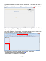
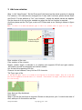
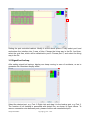
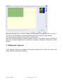
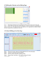
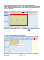
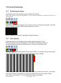
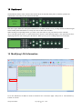
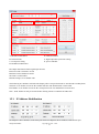
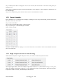
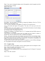
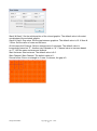
IMPOSA MAGER User’s Manual Version: 1.0.5 WI/QS-PM-M0006 Copyright © 2013 – 2023 1 Updated record Version Updated content Editor Date Ver1.0 Version 1.00 DHY 2013-06-07 Ver 1.0.0 Revised version 1 DHY 2013-08-22 Ver1.0.1 Revised version 2 YSW 2013-09-11 Ver1.0.2 Function update 1 YSW 2013-09-26 Ver1.0.3 Function update 2 YSW 2013-11-23 Ver1.0.4 DVI modification YSW 2013-12-20 Ver1.0.5 Upgrade YSW 2014-9-10 WI/QS-PM-M0006 Copyright © 2013 – 2023 2 Content 1 Software Introduction ...................................................................................................................................... 1 1.1 Software Installation ............................................................................................................................... 1 1.2 Page elements ........................................................................................................................................ 2 2 Build new project ................................................................................................................................................. 3 3 Add new window ................................................................................................................................................. 6 3.1 Signal hot backup ..................................................................................................................................... 7 4 Shifting the Cabinets ............................................................................................................................................ 8 4.1 Shifting the Cabinets on the Editing Page........................................................................................... 9 4.2 Cabinet Shifting on the Main Page ........................................................................................................... 9 5 Custom Tile Setup ...........................................................................................................................................11 5.1 Self-defined Tile .......................................................................................................................................11 5.2 combined cabinet ....................................................................................................................................... 14 6 Displaying setup of cabinet types ....................................................................................................................... 15 7 Print layout ......................................................................................................................................................... 16 8 Brightness control .............................................................................................................................................. 17 8.1 Set the Maximum and Minimum Brightness ..................................................................................... 17 8.2 Manual brightness control ................................................................................................................... 17 8.3 Automatic brightness control ............................................................................................................... 18 8.4 Schedule brightness control ................................................................................................................ 18 9 Color temperature adjustment ............................................................................................................................ 18 10 Gamma adjustment ............................................................................................................................................... 19 11 Freeze window .................................................................................................................................................. 21 12 Blank screen ....................................................................................................................................................... 21 13 Test and Positioning ........................................................................................................................................... 22 13.1 Positioning function .............................................................................................................................. 22 13.2 Test function........................................................................................................................................... 22 14 Dashboard .......................................................................................................................................................... 23 15 Modifying LDU Information.............................................................................................................................. 23 15.1 IP Address Modification .......................................................................................................................... 24 15.2 Power Schedule ....................................................................................................................................... 25 15.3 High Temperature Protection Setting ...................................................................................................... 25 16 Tile status monitoring ...................................................................................................................................... 26 16.1 Examination of the Cabinet Health ......................................................................................................... 26 16.2 Uniformity of Cabinet Information ......................................................................................................... 27 17 Tile test ............................................................................................................................................................... 28 18 Tile indicators and testing buttons setting ...................................................................................................... 29 19 Update tile program............................................................................................................................................ 30 20 Clone tile data..................................................................................................................................................... 30 21 Pixel brightness calibration ................................................................................................................................ 31 22 ArtNet function .................................................................................................................................................. 32 22.1 Graphic clone........................................................................................................................................... 33 WI/QS-PM-M0006 Copyright © 2013 – 2023 3 1 Software Introduction Imposa Mager is a synchronous control software. It has many functions, supporting multi-angle rotation, full HD output, pixel brightness calibration, color temperature adjustment, and Gamma adjustment. Besides, it also supports port hot-backup, Artnet, Genlock, tile testing, image positioning testing, indicator light brightness calibration, tile joint lines printing, tile program upgrade and cabinet cloning. 1.1 Software Installation Step 1: open the folder that contains the IMPOSA Mager software. Step 2: double click to start the installation of NET Framework version 4.0 and IMPOSA Mager. If there is no .NET Framework version 4.0, page in figure below will be shown up, and if it’s installed, enter into Step 4. Step 3: click Accept to continue the installation, and then the.NET Framework version 4.0 will be installed automatically, as shown in figure below. Step 4: select the installation path, taking the default path here as an example, as shown in figure below. To change the installation path, please click Browse and select the target path. WI/QS-PM-M0006 Copyright © 2013 – 2023 1 Step 5: click Next until the installation is finished. Step 6: click Close to finish the installation 1.2 Page elements There are five quick-access panels and the picture shown above is the interface of Design quick-access panel. Screen list LDU list Screen preview area WI/QS-PM-M0006 Copyright © 2013 – 2023 2 2 Build new project Step 1: start IMPOSA Mager, as shown in figure below. Step 2: Press “New Project”,pop up the “new project” page, choose “Empty Project”, revise the project name into “demo project”, choose the location, as the below fig. Press “OK”. Access the Device setting page. Step 3: Drag the left button of the mouse to choose a DVI grid, choose the DVI Output Size as1920x1080, as the below fig. WI/QS-PM-M0006 Copyright © 2013 – 2023 3 DVI Output Size: It is usually the same as the PC output resolution, for example, the PC output resolution is 1920 x 1280 pixels, if the DVI Output Size is set as 1024 x 768 pixels, the synchronous display area will only be 1024 x 768 pixels, and the area will be decreased. After finishing the setting, press “Next”. Step 4: Access DVI Guide. Press the “+”on the right side of the page, set the name and IP address on the popping LDU info setting, set the name as demo, IP as 169.254.18.113 as the below fig. press “OK” to save. The LDU info will be saved in the LDU list on the right side if the page, the list will be save in the local and convenient to use. WI/QS-PM-M0006 Copyright © 2013 – 2023 4 If you want to delete the LDU in the list, you can press the “X” on the top right corner of LDU. Step 5: Drag the LDU in the list into the DVI as the below fig., set the new LDU into the DVI. When revise the LDU in the DVI, please press the “X” on the top right corner of the LDU first, then drag the new LDU into the DVI. After completing the setting, press “Finish”. After adding the project, as the below fig., the software page will show the current project location and the name, LDU list will show the LDU we have added. If you want to revise the Device, press the “Device Setting” on the panel. The new project should be saved in time, press . The next chapter is for establishing a new window. WI/QS-PM-M0006 Copyright © 2013 – 2023 5 3 Add new window Step 1: click “New Screen”. Set the Rows and Cols based on the actual quantity of cabinets. For instance, if 40 cabinets are arranged into 5 rows and 8 columns, please set as Row5 and Cols 8. For the attribute of “Uni” and “channel”, usually the default values are applied. Set the channel of Art-net as the needed one when the Art-net function is required. And then please set the Tile Type, such as VFI P8mm and so on. Setting is shown in figure below. Note: If there is no desired cabinet type in the list, please refer to Type 6 in the list: Setting keys for different shapes Row: number of tile rows Cols: number of tile columns Rotate: rotation angle. It defaults to no rotation and supports 90°left and right rotation, 180°rotation as well as horizontal and vertical rotation. Uni: Art-net Uni,supporting 256 Uni. Channel: Art-net channel, every Uni has 512 channels. Tile Type: type of tile In the above figure, there is a column of setting keys of different shapes. They are to set the position arrangement of the cabinets. For instance, if we choose a triangle, then several cabinets will be missing. Here tiles are fully distributed. Click “Next”. Step 2: Set the tile joint lines as required. Shown as next picture, port 1 controls two rows of tiles, while port 2 controls the rest tiles. WI/QS-PM-M0006 Copyright © 2013 – 2023 6 Setting the port controlled cabinet. Modify it as the above picture. Firstly select port1 and scale-down the interface into 2 rows of tiles. Choose the lining way in the Dir. And then, select the rest tiles, which will be defaulted to port2. Choose port 2, and select the lining way in the Dir. 3.1 Signal hot backup After setting signal hot backup, display can keep running in case of accidents, so as to guarantee the consistent display effect. Select the desired port, e.g. Port 2. Right click and drag it to the backup port, e.g. Port 3. The function of hot backup is presented with dotted line, as shown in figure above. To remove connection wire between ports, please click the red cross behind port. WI/QS-PM-M0006 Copyright © 2013 – 2023 7 Select the desired LDU, e.g. LDU 0. Right click and drag it to the backup LDU, e.g. LDU 1. The function of hot backup is presented with dotted line, as shown in figure above. To remove backup, please click the red cross behind LDU. After this setting is finished, if cabinet position needs to be modified, please click Next to enter the corresponding interface to realize the operation. Otherwise, please click “finish” directly. 4 Shifting the Cabinets If the cabinets should be arranged with specific requirements, users can achieve the desired effect by shifting the cabinets. WI/QS-PM-M0006 Copyright © 2013 – 2023 8 4.1 Shifting the Cabinets on the Editing Page Step 1: Choose the cabinets from the graphical interface or from the chart on the right. Step 2: Push CTRL and shift the chosen cabinets, or shift the cabinets by modifying the values on the chart. In the above picture, the cabinets on the right side are shifted towards left and overlap with the cabinets on their left. 4.2 Cabinet Shifting on the Main Page Step 1: Step 2: Step 3: Step 4: Choose the screen where the target cabinets are on the main page. Choose the cabinets by pushing SHIFT Shift the chosen cabinets by pushing CTRL Repeat Step 2 and Step 3 until cabinet shifting is finished. WI/QS-PM-M0006 Copyright © 2013 – 2023 9 Step 5: Click Send Setting. In the above picture, the 4 cabinets on the 4 corners are drawn towards outside. Please note that, there is a button Attach in the Setting Menu, which activates the adhesion function. When being shifted, the adjacent cabinets will be joined together when they are put close to each other. To modify the window, please double click the window to enter the modification page. In case of any urgent events, please save the file by clicking on the shortcut interface after modification. Click on the “Zoom Out” on the shortcut interface to adjust the size of preview area. Choose a window and move the mouse to shift the cabinets, and we can see a progress bar which shows the settings are being sent to the display. In the picture below, the window within the DVI scope is the display area for synchronous control. DVI Area Cancel the Online check box in the SETTING of the shortcut interface to preserve the WI/QS-PM-M0006 Copyright © 2013 – 2023 10 settings while shifting the window. Then click on Send Setting. Users can also use Move To and input the coordinate values to shift windows. If Lock check box is chosen, the current window will be locked and cannot be moved. If Lines are cancelled, the nonius lines will be hidden. The information of the screen is shown on top of the screen window. In the above picture, it shows that the coordinate of the left top of the cabinet tile 0 in the screen is (83, 76), GAMMA 1.8, 9300K (color temperature) and 100% brightness. The wiring is for seeing from the front. 5 Custom Tile Setup 5.1 Self-defined Tile Our software supports custom arrangement of the modules. Users can set the patterns and positions of the modules according to actual situations. WI/QS-PM-M0006 Copyright © 2013 – 2023 11 Step 1: Choose Self Define Type in the Tile Type list when setting up a screen or modifying the screen properties. Then a Custom Tile window will show as in the above picture, and users can set the sizes and patterns of the tiles. Step 2: Modify the sizes of the cabinets and tiles. In the above picture, size of cabinets is modified as 192x96 and tiles 24x48. Step 3: Click on N at the front of the list which is at the right bottom and change it into Y. Now all the tiles are shown on the left interface, and the default setting is showing all the tiles on left top. Step 4: WI/QS-PM-M0006 Copyright © 2013 – 2023 12 Shift the tiles either by moving the tiles in the graphical interface, or by modifying the coordinate value in the form on the right. Step 5: To change the direction of tiles, choose the target tile and change the rotation angle. In the above picture, the two columns of tiles in the middle are rotated 90°to the left. Step 6: Click on OK when the setting is finished, and the effect is shown as below. If users need to change other settings of the tiles, please move to the next steps. Otherwise, please click on Next to enter the wiring window. Step 7: In the above picture, users can double click the cabinet to modify the parameters of the cabinet or tiles. Choose the target cabinet on the right of the custom tile window, for example, tile 0, and modify the tile’s position. Here, the two horizontal tiles right below are rotated to the right by 90°. WI/QS-PM-M0006 Copyright © 2013 – 2023 13 Step 8: Click OK after the modification. 5.2 combined cabinet For combined cabinets, the IMPOSA Mager software can achieve separated control on different types of cabinet in the same display. Choose COMBI cabinet type . Set the cabinet quantity, arranging mode as well as cabling mode as with ordinary cabinet. After setting up the cabling mode, enter into the special setup interface for the combined cabinets. Please refer to the following figure WI/QS-PM-M0006 Copyright © 2013 – 2023 14 Here, you can set displaying content of specific position in a combined cabinet, set the video signal of displaying DVI, as well as set the display content of ArtNet. 6 Displaying setup of cabinet types The IMPOSA Mager software can set different cabinet types in the list. Step1: click“menu”and choose preference. As the figure shows, left side is the type library, with software supportive cabinet types. And the right side shows the current cabinet types. WI/QS-PM-M0006 Copyright © 2013 – 2023 15 Step 2: choose your desired cabinet types in the left-side list. Step 3: click >> bottom to add your desired cabinet type into the right-side list. Bottom >>> can add all kinds of cabinet types to the type owner list while bottom <<< can add all content in the type owner list to the type library list. Step 4: click OK to save your setup. 7 Print layout This software supports layout printing, which makes the display connection convenient for staff. Select the window to be printed, click “Print Layout” on the shortcut panel and then click “OK” on the printing page to print layout, as shown in figure below. The printed layout diagram shows the layout of the back side of the display, contrary to the layout shown in the software, shown as below: WI/QS-PM-M0006 Copyright © 2013 – 2023 16 8 Brightness control This software supports manual, auto and schedule brightness control. Brightness control toolbar is in the DESIGN page, as shown in figure below. Min: to minimize the display brightness. Less: reduce a percentage of brightness in the current brightness level until the minimum brightness is reached. More: increase a percentage of brightness in the current brightness level until the maximum brightness is reached. Max: to maximize the display brightness. Advanced: advanced setting page, as shown in figure below. In the next chapter, function of brightness control will be introduced. 8.1 Set the Maximum and Minimum Brightness On the Advanced Page, select the value for Min Brightness and Max Brightness in the drop-down list. For example, as shown in figure above, set the Max Brightness as 40% and Min Brightness as 5%. Click on “OK” to save the setting. 8.2 Manual brightness control Method 1: Input value on the input box in the middle of the Brightness page, and then select the “%” check box, which shows that the brightness can be set by hundred percentage point system. It will be set by values if the “%” check box is not selected. Method 2: On the Advanced Page, select the “Manual” radio box, and then choose the hundred percentage value in the drop-down list. Click “OK” to save the setting. WI/QS-PM-M0006 Copyright © 2013 – 2023 17 8.3 Automatic brightness control Method 1: Input “0” in the input box in the middle of the Brightness page, and then press “Enter” to do the setting. Method 2: On the Advanced Page, choose the “Auto” radio button, and then click “OK” to save the setting. 8.4 Schedule brightness control Step 1: On the Advanced page, select the “Schedule” radio button. Step 2: Select a check box of a time period. Step 3: Set the “Start Time” and “End Time”, and set the brightness for this time period. Step 4: Repeat Step 2 and 3 to set up all the time periods needed. Step 5: Modify the brightness on the “Default” period, which is “automatic adjustment” originally. Step 6: Click “OK” to save the setting. As shown in figure below, the brightness will be 1% from 0: 00 to 7: 00 and 3% from 7: 00 to 9:00, and it will be in automatic adjustment in the rest time. 9 Color temperature adjustment Step 1: Select the window, and click “Color”. Step 2: select “Advanced” to open window of Color Temperature. WI/QS-PM-M0006 Copyright © 2013 – 2023 18 Step 3: click “Load”, to open window of “Load Color Temperature”. Step 4: Select the correct screen type, choose data of P8 here, click on the “Load”. If color temperature needed to be set, then continue to the next step, otherwise proceed to Step 7 Step 5: Adjust the RGB scroll bar to the proper value, if “Live” option have been checked, live effect will be shown on the display every time after adjustment. Step 6: click on “save to custom” to set brightness value. Step 7: click on “OK”, color temperature setting will be sent to the screen, and then exit the page Step 8: click on “Color” on REVISE panel, select the color temperature which needed to be adjusted, and activate it. 10 Gamma adjustment Select the window and click “Gamma”. WI/QS-PM-M0006 Copyright © 2013 – 2023 19 Select “Advanced” to set the Gamma value, such as setting Gamma 2.2. Step 1: select “GAMMA2.2” for “Item”. Step 2: select “B, Blue” for “Color”. Step 3: type in digits in “Parameter”. Step 4: click “Calculate” and the Gamma curve will be shown on the coordinate. Step 5: select “R” and “G” in turn for “Color”, and set the Gamma value respectively, following the instruction of Step 3 and Step 4. Setting is shown in figure below. Step 6: click “OK” and the Gamma value will be sent to the display, as shown in figure below. Click “X” to exit the page. WI/QS-PM-M0006 Copyright © 2013 – 2023 20 Step7: select “Gamma2.2” under “Gamma”, and activate it. Position of the current window, Gamma color temperature and brightness can be seen in software. 11 Freeze window The function of Freeze window is to freeze the content in the current computer screen. The synchronous output content to the display will be the content under freezing regardless of any change of the content on the computer screen. If the screen is moved, it will run the content in the corresponding positions under the frozen condition. Step 1: select the window and click “Freeze” in the toolbar to freeze the window. The LDU will be in frozen condition and it shows “SYSTEN IN FREEZE” on the LCD page. Step 2: to cancel the freeze, please click “Live”. LDU will be out of frozen condition and shows normal information. 12 Blank screen The blank screen setting should follow the steps as below: Step 1: select the window and click “Blank” on the page. LDU will be in frozen condition and the LCD page will show “SYSTEN IN BLACK”; Step 2: To cancel the blank, please click “Live”. LDU will be out of the frozen condition and shows normal information. WI/QS-PM-M0006 Copyright © 2013 – 2023 21 13 Test and Positioning 13.1 Positioning function Positioning function can facilitate users to position the cabinet. Select the window. Click the drop-down of "Test" item on the panel, and choose “Tile 0” as shown below: Page shown as below will appear on the computer screen and be synchronized to the LED screen, to show position of cabinets and wiring way to users. Click on “stop” or “X” beside on the panel to stop positioning. 13.2 Test function Positioning function can facilitate users to test cabinets’ problems, if any. Select the window, click on drop-down of “Test” item on the panel, choose the corresponding test content as following picture, Choose color gradient here. The following window will be shown on the same location of computer, and synchronously display the image on the screen, it can be changed via options beside. If LDU option is chosen, then the test image will be sent via LDU to the screen, in this case, even if the computer commands no output sync signal, the screen can still be tested. Click “Stop” on the panel or “X” at the right-hand side to stop testing. WI/QS-PM-M0006 Copyright © 2013 – 2023 22 14 Dashboard The dashboard enables remote check of the content shown on the LDU front panel, so that the operator can control LDU even if they are not in front of the LDU. The above figure shows the front panel information of an LDU named 135. Its pressing buttons & indicator light status & LDU panel information are exactly the same as that of the real LDU. When clicking corresponding buttons, you achieve the same effect as you press buttons on the real LDU. Above all LDU panels, there is a panel named ALL (shown as the following figure). This panel doesn’t have displaying function. You can only press the buttons. When you do, you are sending instruction to all LDUs. For example, if you click “Black”,all connected LDU will execute this “Black” command. 15 Modifying LDU Information Click the LDU whose IP address needs to be modified in the main page. And you will see LDU Config. window as below: WI/QS-PM-M0006 Copyright © 2013 – 2023 23 A C B D G E F A: Modified LED address B: Genlock status C: Visual pixel setting D: IP address modification E: LED information F: high temperature protection setting G: power Schedule DVI Input: Resolution of DVI signal input to LDU Firmware: LDU’s firmware version Hardware: LDU’s hardware model SN: LDU’s serial number Default Settings: Set to default value The following two attributes will affect the display effect. Non-professionals are not advised to modify them: Genlock: to set whether to activate the Genlock function. The default mode is inactivated. Pixel Mode: to set whether to activate the virtual pixel mode. It is defaulted to be inactivated. Note: ‘Send’ button can only be activated after clicking ‘Read’ to read back the LDU info. 15.1 IP Address Modification Net Adapter1 shows attributes of the main port while Net Adapter2 shows attributes of the ArtNet port. WI/QS-PM-M0006 Copyright © 2013 – 2023 24 Step 1: modify the IP address. Change the IP to 169.254.10.156, sub network mask to 255.255.0.0 and gateway to 169.254.11.171. When doing the modification, please note that the IP address of Net Adapter 1 and Net Adapter 2 should not be on the same IP range. Step 2: After modification, please click the button ‘Send’. Then modification is done. 15.2 Power Schedule Power Schedule is to set working time for displays, enabling it to work only in the desired period of time and to shut down for the rest of the time. Step 1: click the checkbox Step 2: set the On Time and Off Time for power supply; Step 3: repeat step1 & 2, until finishing the schedule; Step4: send the settings The above schedule means the display is set to work from 8:00~13:30 and from 18:00~1:00 and shall shut down for the rest of the time. 15.3 High Temperature Protection Setting When cabinet temperature is higher than preset value, the cabinet will enter into protection status. As the upper figure shows, when 10% modules’ temperature reaches 55°C, there will be warning on LCD panel; When 20% modules’ temperature reaches 60°C, the LED display will go to half brightness; When 30% modules’ temperature reaches 75 Celsius, the LED display will black out. WI/QS-PM-M0006 Copyright © 2013 – 2023 25 16 Tile status monitoring Enter into “MONITOR” page, and it shows the tile working status. Click “Refresh” to refresh the status information. The status information can be checked after closing the prompt page, as shown in figure below. Green color means tiles are in normal working and blue color means tile status information is not refreshed. Abnormal tile working is marked with red color. For detailed tile information, please check in Report. Monitor Report 16.1 Examination of the Cabinet Health This function can obtain the information of all the cabinets. Click the health button, the software will acquire the CPU, FPGA, GAMMA, Config, Driver Table and Chromaticity information. WI/QS-PM-M0006 Copyright © 2013 – 2023 26 Once the examination is finished, the result of the uniformity will be shown on the software surface. It means that the information of the cabinets is uniform if the color is the same. As the following picture shows, the information of the preceding ten cabinets is uniform. But the connection of the twelfth one failed. 16.2 Uniformity of Cabinet Information After we check the health of the cabinets, we can adjust their information to be the same. Click the Repair button, and you will be prompted to choose one cabinet as a benchmark. WI/QS-PM-M0006 Copyright © 2013 – 2023 27 After choosing the benchmark, there is a dialog box for you to check the information to adjust.) All the cabinets will be set to meet the conformity after choosing. 17 Tile test Enter MAINTENCE and TEST Step 1: Select the test tile in the left list; Step 2: Choose the testing item. E.g. choose “Red”, the screen will show red color only; Step 3: Click “stop” to finish the test. See as follow. Tile list is on the left.”0” tile in Port I has been selected. The test result will be shown under “Command” at the bottom right; the progress bar shows the test schedule. WI/QS-PM-M0006 Copyright © 2013 – 2023 28 Tile test button list All red All green All blue All white Horizontal scanning Vertical scanning Bias scanning Reboot the tile Auto change Stop the test Gradient Wipe Blank Tile information is based on modules Indicator light at the back of the cabinet 18 Tile indicators and testing buttons setting Enter MAINTENANCE and Setting Step 1: select the screen to be modified. Step 2: select Enable or Disable in the drop-down list of Test Button. Step 3: select Close Indicator, Min Brightness, Mid Brightness or Max Brightness in the drop-down list of Indicator Brightness. Step 4: click Setting to send it to the tile. As shown in figure below, SCREEN 0 is selected for setting. Test Button is available. Indicators behind tiles are closed. Commands below show the setting result. Progress bar shows the setting progress. WI/QS-PM-M0006 Copyright © 2013 – 2023 29 19 Update tile program Enter MAINTENANCE and Update and input the password when the page occurred as below, default is mager. Click OK to enter the Update page. Step 1: select the tiles that need program upgrade. Step 2: select the program to be upgraded. Step 3: click “Upgrade”. Note: Before upgrading tiles, please refresh tile information first. For further details, please refer to the Tile status monitoring above. As shown in figure below, Gamma of Tile 11 is selected for upgrade. Commands show the testing result. Progress bar shows the testing progress. 20 Clone tile data Enter MAINTENANCE and Clone. Input password in the page occurred, which is mager by default. Enter into the Clone page. Step 1: select the current screen. WI/QS-PM-M0006 Copyright © 2013 – 2023 30 Step 2: select the tile that needs data clone. Step 3: select tiles to be cloned. Multiple tiles can be selected. Step 4: select data to be cloned. Step 5: click “Clone” to clone data. As shown in figure below, data of port1-0 tile is cloned to Tile 13 and 14. 21 Pixel brightness calibration Enter Calibration page. Select the window to be calibrated in the left side. Click “Adjust”. Input password in the page occurred, which is mager2 by default. Step 1: select the tile to be calibrated. Step 2: select the zone to be calibrated. Step 3: set the calibrated brightness. You can set the increase or decrease brightness ratio here (per ten thousands). click "+" or "-" to increase or decrease the brightness. Step 4: click “apply” to put into use the setting and then set data for other tiles and tiles. Step 5: click “send” to deliver data of brightness calibration. Step 6: click “Turn On Correction” to start brightness correction. To close correction, please click “Turn Off Correction”. WI/QS-PM-M0006 Copyright © 2013 – 2023 31 1 2 3 4 5 6 Function buttons on the panel can also be used for brightness calibration. Return to the main page CALIBRATION and click “Turn On Correction” to activate brightness calibration. To close correction, please click “Turn Off Correction”. To reset to default brightness, click "Factory Reset". If Do not save, just show effect is checked, the brightness data will be sent to the panels. 22 ArtNet function ArtNet can support overlay of the following graphic above the display content. The selected tile by rectangular box on the left top is to emphasis the display content of this tile. Step 1: Select the shape in DRAW list, like rectangle, circle, character, graphic etc. Step 2: Draw the graphics within the DVI signal; Step 3: Double-click the Shape Property as follow: WI/QS-PM-M0006 Copyright © 2013 – 2023 32 Step 4: If you want to change the display order of the graphics, select the graphic and click arrange bar button to change. Step 5: Click “send”. Line Width: You can choose 1~10 pixels to change the boldness of the line. Fill: Set whether to fill in the graphic or not X & Y: The start coordinates of the graphics. The value of X can only be even. W & H: The width and height of the graphics. The value of W can only be the even numbers. Init Color: Set the color of the graphics. If connected with Art-Net device, then the display color will be the same with the device setting. Uni: Set the universe. The Default Value is 1-0. Channel: Set channels. The Default Value is 0. “0” indicates that the R/G/B values are controlled by 1, 2, 3 channels. If this function is not required, please select the graphic and click “delete” to delete; or directly click “clear all” and then click “send” to delete all the graphics. Notice: You need to set the text, font and size if you choose “Text”; If you choose “image”, you need to set the source of the image. Picture showed on the screen is the shape of the image. The value of the color can be set. If some part of the picture is transparent, the transparent part will keep the same on the display. You can check the exist universe and channel of the graphics on the left Device Manager list. The graphics will be shown all together in the same channels. 22.1 Graphic clone Clone function can copy the graphic, and the copied graphics can be arranged in order. Step 1: Select the graphic that needs to be cloned. Step 2: Click the clone button in draw list; Step 3: See the clone setting as follow. Set the starting point as (0, 0), Gap as 0, 2 rows and 3 columns; Step 4: Click “OK” and send. WI/QS-PM-M0006 Copyright © 2013 – 2023 33 StartX & StartY: Set the initial position of the cloned graphic. The default value is the start coordinates of the selected graphic; GapX & GapY: Gap value. Set the gap between graphics. The default value is 10. X Num & Y Num: Set the value of rows and columns. Alt Universe And Channel: Set the arrangement of universes. The default value is increasingly based on “Z”. Another way is based on “N”. Channel value is increase based on “Z”. Use the same universe and channel. Start Universe: Start universe. The default value is 0-0. Start Channel: Start Channel. The default value is 0. See as follow. Clone a rectangle to 2 rows 3 columns, the gap is 0. WI/QS-PM-M0006 Copyright © 2013 – 2023 34