1
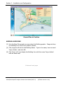
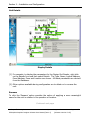
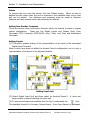
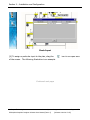
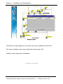
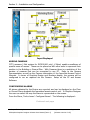
GRAPHICS DESIGNER
From : Version 3.22
SOFTWARE USER MANUAL
Manual ref. No. IXP331-0-0-GB-03
Issue 4
March 2006
IMPORTANT NOTICE
In the event of any discrepancies in meaning between this, the original English
version of the manual, and any other version of this manual, in whatever language,
the information in this version shall take precedence.
IMPRO TECHNOLOGIES (PTY) LTD - SOFTWARE LICENSE AGREEMENT
READ THE TERMS AND CONDITIONS OF THIS LICENSE AGREEMENT CAREFULLY BEFORE OPENING THE PACKAGE CONTAINING THE PROGRAM DISKETTES
OR CD-ROM, THE COMPUTER SOFTWARE THEREIN, AND THE ACCOMPANYING USER DOCUMENTATION (THE “PROGRAM”). THIS LICENSE AGREEMENT
REPRESENTS THE ENTIRE AGREEMENT CONCERNING THE PROGRAM BETWEEN YOU AND IMPRO TECHNOLOGIES (PTY) LTD. (THE LICENSOR) AND IT
SUPERSEDES ANY PRIOR PROPOSAL, REPRESENTATION, OR UNDERSTANDING BETWEEN THE PARTIES. BY OPENING THE PACKAGE CONTAINING THE
PROGRAM, YOU AND YOUR COMPANY (COLLECTIVELY “YOU”) ARE ACCEPTING AND AGREEING TO THE TERMS OF THIS LICENSE AGREEMENT. IF YOU ARE
NOT WILLING TO BE BOUND BY THE TERMS OF THIS LICENSE AGREEMENT, YOU SHOULD PROMPTLY RETURN THE PACKAGE IN UNOPENED FORM, AND
YOU WILL RECEIVE A REFUND OF YOUR MONEY.
1.
demands, or action arising out of or relating to this Agreement shall not exceed the
License fee paid for the use of the Program.In no event shall Licenser be liable for
any indirect, incidental, consequential, special or exemplary damages or lost profits,
even if Licenser has been advised of the possibility of such damages.
LICENSE GRANT
Licenser hereby grants you, and you accept, a non exclusive
license to use the Program CDROM and the computer software
contained therein object-code-only from (collectively referred to as
the Software), and the accompanying User documentation, only as
authorised in this License Agreement. The Software may be used
only on a single computer owned, leased, or otherwise controlled
by you; or in the event of the inoperability of that computer, on a
backup computer selected by you. Concurrent use on two or more
computers is not authorised without the advance written consent
of Licenser and the payment of additional license fees. You agree
that you will not assign sublicense, transfer, pledge, lease, rent, or
share your rights under this License agreement.
2.
7.
HIGH RISK ACTIVITIES
The software is not fault-tolerant and is not designed, manufactured or intended for
use or resale as on-line control equipment in hazardous environments requiring failsafe performance, such as in the operation of nuclear facilities, aircraft navigation or
communication systems, air traffic control, direct life support machines, or weapons
systems, in which the failure of the Software could lead directly to death, personal
injury, or severe physical or environmental damage (“High Risk Activities”). Impro
and its suppliers specifically disclaim any express or implied warranty of fitness for
High Risk Activities.
LICENSOR RIGHTS
8.
TRADEMARKS
You acknowledge and agree that the Program consists of
proprietary, unpublished products of Licensor, protected under
Copyright Law and trade secret laws of general applicability. You
further acknowledge and agree that all right, title, and interest in
and to the Program are and shall remain with Licensor. This
License Agreement does not convey to you an interest in or to the
Program, but only a limited right of use revocable in accordance
with the terms of this LICENSE Agreement.
ImproX, ImproNet, IXP, and other names included therein are trademarks of Licensor.
No right, License or interest to Licensor trademarks are generated hereunder, and
you agree that no such right, License or interest shall be asserted by you with respect
to such trademarks.
3.
10.
9.
LICENSE FEES
TERM
This License Agreement is effective upon your opening of this
package.
5.
11.
SEVERABILITY
Should any item of the License Agreement be declared void or unenforceable to any
court of competent jurisdiction, such declaration shall have no effect on the remaining
terms hereof.
LIMITED WARRANTY
Licensor warrants, for your benefit alone, that the program
diskettes in which the computer software is embedded and the
user’s manual shall, for a period of 90 days from the date of
commencement of this License Agreement (referred to as the
warranty period), be free from defects in material and
workmanship. Licensor further warrants, for our benefit alone,
that during the Warranty Period the Program shall operate
substantially in accordance with he functional specifications in the
User’s Manual. You agree that the foregoing constitutes your sole
and exclusive remedy of breach by Licensor of any warranties
made under this Agreement. EXCEPT FOR THE WARRANTIES SET
FORTH ABOVE, THE PROGRAM, AND THE SOFTWARE CONTAINED
THEREIN, ARE LICENSED “AS IS” AND LICENSOR DISCLAIMS ANY
AND ALL OTHER WARRANTIES, WHETHER EXPRESS OR IMPLIED,
INCLUDING (WITHOUT LIMITATION) ANY IMPLIED WARRANTIES
OF MERCHANTABILITY OR FITNESS FOR A PARTICULAR
PURPOSE.
6.
COSTS OF LITIGATION
If any action is brought by either party to this License Agreement against the other
party regarding the subject matter hereof, the prevailing party shall be entitled to
recover, in addition to any other relief granted, reasonable attorney fees and
expenses.
The License fees paid by you are paid in consideration of the
licenses granted under this License Agreement.
4.
GOVERNING LAW
This License Agreement shall be construed and governed in accordance with the laws
of Republic of South Africa.
12.
NO WAIVER
The failure of either party to enforce any rights granted hereunder or to take action
against the other party in the event of any breach hereunder shall not be deemed a
waiver by that party as to subsequent enforcement of rights or subsequent actions in
the event of future breaches.
13.
RD
USE WITH 3
PARTY EQUIPMENT
THE USE OF THIS SOFTWARE WITH A CARD PRINTER (OR ANY OTHER 3RD PARTY
EQUIPMENT) IS UNDERTAKEN AT THE CLIENT’S OWN RISK. IMPRO WILL NOT
ACCEPT LIABILITY FOR ANY DAMAGE TO SUCH EQUIPMENT CAUSED BY
INCOMPATIBILITIES BETWEEN IMPRO TECHNOLOGIES’ SOFTWARE AND THE SAID
EQUIPMENT.
LIMITATION OF LIABILITY
Licensor’s cumulative liability to you or any other party for any loss
or damages resulting from any claims,
impro
R
Technologies (Pty) Ltd
(website)
http:// www.impro.net
Reg. No. 90/06574/07
READ THIS BEFORE OPENING THE ENVELOPE CONTAINING THE SOFTWARE
© March 2006 Impro Technologies
Data subject to change without notice
IXP300/400 Graphics Designer Software User Manual [Issue 4]
[Software Version V3.22]
Page
3
Blank Page
© March 2006 Impro Technologies
Data subject to change without notice
IXP300/400 Graphics Designer Software User Manual [Issue 4]
[Software Version V3.22]
Page
4
LIST OF CONTENTS
SECTION 1 – AN OVERVIEW OF THE GRAPHICS DESIGNER.................................... 9
SCOPE ............................................................................................................. 9
RELATED PUBLICATIONS .................................................................................. 9
WELCOME ........................................................................................................ 9
SECURE INSTALLATION .................................................................................. 10
SAVING THE GRAPHICS FILES......................................................................... 10
REQUIREMENTS ............................................................................................. 10
DEFINITIONS AND TERMINOLOGY .................................................................. 11
ImproX Units .............................................................................................. 11
Base plan ................................................................................................... 12
Ground Plan ............................................................................................... 13
Building ...................................................................................................... 15
Floor Plan ................................................................................................... 15
Floor Plan Examples .................................................................................... 17
Simple Floor Plan .................................................................................... 17
Detailed Floor Plan .................................................................................. 17
RELATIONSHIP HIERARCHY ............................................................................ 19
SECTION 2 – INSTALLATION AND CONFIGURATION ............................................ 23
INTRODUCTION ............................................................................................. 23
Date/Time Formats ..................................................................................... 23
Disk Space Requirements ............................................................................ 24
INSTALLATION ACTIONS ................................................................................ 24
CONFIGURING THE GRAPHICS DESIGNER - INITIAL OPERATIONS.................... 24
Access Software.......................................................................................... 24
Graphics.Properties ..................................................................................... 25
Starting Graphics Designer .......................................................................... 25
CONFIGURING THE GRAPHICS DESIGNER - DATABASE SETTINGS .................... 25
GRAPHICS DESIGNER START .......................................................................... 26
ADDING A BASE PLAN..................................................................................... 29
ADDING A GROUND PLAN ............................................................................... 30
ADDING A BUILDING ...................................................................................... 32
ADDING A FLOOR PLAN .................................................................................. 34
ADDING CONTROLLERS .................................................................................. 37
ADDING TERMINALS....................................................................................... 40
Filtering...................................................................................................... 40
Filtering Example ........................................................................................ 40
Adding Readers and Non-Readers to the Controllers ..................................... 41
Altering an Icon .......................................................................................... 44
Unit Details................................................................................................. 45
Rename .................................................................................................. 45
Delete .................................................................................................... 46
Adding Non-Reader Terminals...................................................................... 46
Adding Inputs ............................................................................................. 46
ADDING CAMERAS.......................................................................................... 49
CONFIGURING ALARMS .................................................................................. 49
© Impro Technologies
Data subject to change without notice
IXP300/400 Graphics Designer Software User Manual [Issue 4]
[Software Version V3.22]
Page
5
Alarms, General .......................................................................................... 50
Alarms, Advanced ....................................................................................... 51
ADDING CADDX ALARMS ................................................................................ 53
General ...................................................................................................... 53
CaddX Icons ............................................................................................... 54
ADDING ZITON ALARMS ................................................................................. 54
General ...................................................................................................... 54
Adding a Ziton Fire Alarm Panel to the Floor Plan.......................................... 56
Adding a Ziton Fire Alarm Sensor to the Floor Plan........................................ 56
Deleting or Renaming a Ziton Fire Alarm Sensor or Panel icon ....................... 57
GRAPHICS DESIGNER - END............................................................................ 58
MODIFICATIONS ................................................................................................ 58
INDEX ............................................................................................................... 59
© Impro Technologies
Data subject to change without notice
IXP300/400 Graphics Designer Software User Manual [Issue 4]
[Software Version V3.22]
Page
6
Section 1 – Graphics Designer Overview
SECTION 1
GRAPHICS DESIGNER
OVERVIEW
© Impro Technologies
Data subject to change without notice
IXP300/400 Graphics Designer Software User Manual [Issue 4]
[Software Version V3.22]
Page
7
Section 1 – Graphic Designer Overview
Blank page
© Impro Technologies
Data subject to change without notice
IXP300/400 Graphics Designer Software User Manual [Issue 4]
[Software Version V3.22]
Page
8
Section 1 – Graphic Designer Overview
SECTION 1 – AN OVERVIEW OF THE GRAPHICS DESIGNER
SCOPE
This manual contains all the information necessary to correctly install and configure the
Impro Graphics Designer Software.
RELATED PUBLICATIONS
The following related publications are produced by Impro Technologies :
IXP 300/400 ImproNet Access Control System Software User Manual. The Graphics
Designer and Graphics Runtime Software are available as optional utilities for
IXP300/400 Systems.
IXP200 Access Control System Software User Manual. The Graphics Designer and
Runtime Software are integrated into the supplied software suite in the IXP200
software.
ImproX Hardware Installation Manuals. An Installation Manual is supplied with each
individual hardware unit.
NOTES:
1. The Graphics system is designed for use with Windows 2000, NT or XP
Professional. While Windows 98 or XP Home can be used they suffer connection
problems to remote databases and are therefore not recommended.
2. This manual deals with the Graphics Suite as a whole . Please note thatsome of
the features discussed are not implemented in the IXP200 Version.
WELCOME
The Impro Graphics Designer Software provides a process by which the physical
placement of the access control system units in buildings and other areas on an access
controlled Site can be graphically represented on an attached computer (PC).
There are two software programs involved. The first, ‘Graphics Designer’, is the
subject of this manual which describes the installation and use of the Graphics
Designer Software.
This process enables the user to input the graphical
representations of the System and position the various Controllers, Readers, and digital
interfaces in an overall pictorial representation of the position in which these are
installed in relation to the building floors or ground area. The second program is the
Graphics Runtime Software. This is the operating level of the graphics display of the
status of the Access Control System. Its use is described in the IXP300/400 Graphics
Runtime Module Software User Manual.
© Impro Technologies
Data subject to change without notice
IXP300/400 Graphics Designer Software User Manual [Issue 4]
[Software Version V3.22]
Page
9
Section 1 – Graphic Designer Overview
SECURE INSTALLATION
It is suggested that the Designer and Run Time Software should be installed on a
secure PC to limit the possibility of the setup being tampered with. Both programs are
password protected.
SAVING THE GRAPHICS FILES
Graphics Designer automatically saves on program exit. In the case of the IXP200 the
Graphics information is part of the System and is thus also automatically saved.
REQUIREMENTS
Before installing and implementing the software there are some important
requirements:
[1] The Graphics display needs access to the System Database to identify and access
the ImproX units available. In the case of IXP300/400 this implies that the
Graphics PC can be remotely situated as long as it has a LAN connection to the
ImproNet Database. Of course, in the case of IXP200, all software is installed on
the same, single PC.
[2] Before installing and configuring the Graphics Designer, the Base plan, Ground
plan and Building Floor plans must be prepared. Most of this preparation should
have been done during the installation and implementation of the access control
System. The Installation chart indicating the types and numbers of the installed
units, and in which floor or area they are located, is needed to help identify and
configure the installed units into a working display.
[3] The plans needed must be in Jpeg or .gif format (<name>.jpg or <name>.gif).
These do not have to be intricate detailed architectural drawings. They can be
roughly drawn or scanned images (see examples below). What is important is that
the location of the various devices which are to be monitored as part of the
Graphics Software must be accurately named and located using Graphics Designer
[4] For secure and rapid live on-line display the minimum recommended PC
configuration is as follows:
•
For IXP300/400 :
•
•
Pentium 3 (1GHz or Faster), 512MB RAM, Monitor capable of 1024x768 (24 Bit
Colour) with equivalent Graphic Display Adapter, 1GB free Hard Disk Space, 1
free RS232 Comm Port, CD-ROM drive, Mouse and Keyboard.
For IXP200:
•
See the IXP200 System Software User Manual.
Continued next page
© Impro Technologies
Data subject to change without notice
IXP300/400 Graphics Designer Software User Manual [Issue 4]
[Software Version V3.22]
Page
10
Section 1 – Graphic Designer Overview
DEFINITIONS AND TERMINOLOGY
ImproX Units
The various hardware Units used have identifiable names that are descriptive of their
functions. For example, “ImproX KR Keypad Remote Reader ” and “ImproX IC
Controller”.
Non-reader Terminals can often be identified by the absence of the word “Reader”
from their names, e.g. “ImproX DT Door Terminal”, although some Terminals are also
Readers. The word “Non-reader” is used in this manual to clearly identify these units.
The following table is a summary of some descriptive terms and unit type definitions
and included as a guide to the terminology used in the Access Control System:
Descriptive
Term
Meaning
Controller
A Controller acts as an interface between the System Host PC(s)
and the System Terminals. It performs control functions such as
the real-time control of access to the System, and maintains
databases for System activities.
Keypad
A set of pushbutton keys mounted in the cover of a Terminal (or
Remote Reader) which permits the entry of data, such as a PIN
Code, or a PAC (Personal Access Code), into the System.
Non-reader
A unit which does not have the ability to read from (or write to)
Tags. This term includes Power Supplies and also some Terminals
(and Controllers) that enable the routing of access control
functions but are unable to communicate with Tags.
Reader
A Terminal which has the ability to read from (and typically to
write to) a Tag. Currently, Remote Readers are available for 125
kHz proximity RF and MIFARE 13.5 MHz Tags.
Some Readers have Keypads to permit confirmation of
identification by use of a Personal Identification Number PIN or
Personal Access Code (PAC).
Continued next page
© Impro Technologies
Data subject to change without notice
IXP300/400 Graphics Designer Software User Manual [Issue 4]
[Software Version V3.22]
Page
11
Section 1 – Graphic Designer Overview
Descriptive
Term
Remote Reader
Meaning
A unit which has the ability to read from (and typically to write to)
Tag. A Remote Reader must be connected to a suitable ImproX
Terminal (such as the ImproX DT, TA, TT or PT units) in order to
be able to communicate with the associated system Controller.
Currently, Remote Readers are available for 125 kHz proximity RF
and MIFARE 13.5 MHz Tags.
Remote Readers are called ‘Remote’ because they are remote
from the Controller, as a Terminal must always be connected
between the Controller and the Remote.
Some Remote Readers have Keypads to add the possibility of
confirmed identification by use of a Personal Identification Number
PIN or Personal Access Code (PAC).
Some devices, such as the ImproX IR Infra Red Receiver and the
ImproX RF UHF Receiver are connected into a System in the same
way as Remote Readers, and operate similarly, however their
signal is not read by close proximity but by received signal at a
greater distance.
Terminal
A type of unit that interfaces directly to an Improx Controller via
an RS485 Terminal Bus. Terminals can be Readers or Nonreaders but never Remote Readers.
Base plan
A Base plan is used to define the geographic location where the Building, Ground Plans
and Floor Plan/s are to be located. This location can be represented pictorially by a
photograph, a graphic design or even a satellite picture. There can be only one Base
Plan used for the Graphics Representation per Site.
So, for instance, one can use an aerial photograph of the city or town, or a map.
The practical purpose of the Base Plan is to locate the physical placing of the Site
(Buildings and Ground Plans) in relation to the city, town or industrial area where the
Access Control System is sited. Therefore, we would typically use a representation
from a street map as shown below.. Such a map enables the visual integration of
Buildings and Ground Plans into a geographic Base Plan.
Continued next page
© Impro Technologies
Data subject to change without notice
IXP300/400 Graphics Designer Software User Manual [Issue 4]
[Software Version V3.22]
Page
12
Section 1 – Graphic Designer Overview
We are
here
And here
And here.
Annotated Base Plan
Ground Plan
The Ground Plan defines an open area (not inside a building) where Access Control can
be monitored by Impro Graphics and could be a parking lot or the access points to a
building complex. As with the Base Plan, it is two dimensional and serves to locate
where in the geography the user equipment is positioned. The point of the Ground
Plan is to be more specific than the Base Plan. The requirement is, as before, that the
used image must be in Jpeg or Gif format. This example Ground Plan, below, enables
the positioning of Access Control Units at the Boom Gate and, possibly, a garden
entrance
There can be more than one Ground Plan per Base Plan. So, for example, at a
University where there are multiple Parking Lots and Multiple Buildings these can be
integrated into one Base Plan.
Continued next page
© Impro Technologies
Data subject to change without notice
IXP300/400 Graphics Designer Software User Manual [Issue 4]
[Software Version V3.22]
Page
13
Section 1 – Graphic Designer Overview
Ground Plan
The usefulness of the Ground Plan representation is that it enables the display of open
fields, parking lots, and similar areas which are open air, i.e. not roofed or otherwise
enclosed.
A Second Ground Plan can be added such as this:
Continued next page
© Impro Technologies
Data subject to change without notice
IXP300/400 Graphics Designer Software User Manual [Issue 4]
[Software Version V3.22]
Page
14
Section 1 – Graphic Designer Overview
Second Ground Plan
Building
Adding a Building onto the Base Plan identifies a particular installation. The Building is
the primary location for placing Floor Plans. The building represents a threedimensional area and as many floors can be added as are needed. Remember that on
any Base Plan more than one Building can be placed.
Floor Plan
The Floor Plan is the working Graphics Display of the Building Access Control System.
Into the Floor Plan are placed the units that form the access control System using
Graphics Designer. Right clicking on a Building Icon triggers a request for a Floor Plan
to be inserted.
The preparation of a Floor Plan makes the procedure of installation and configuring
easier. The Floor Plan, illustrated in the next diagram, is the one we have used in
describing the process of installation and configuration. The Floor Plan has been
prepared using a convenient drawing software package commonly available.
Continued next page
© Impro Technologies
Data subject to change without notice
IXP300/400 Graphics Designer Software User Manual [Issue 4]
[Software Version V3.22]
Page
15
Section 1 – Graphic Designer Overview
Floor Plan
NOTE : The above Floor Plan is clear of all icons and pictures. The Floor Plan used
later in this document includes pictures of the units that are to be installed.
By using the latter Floor Plan a pictorial description is made easier in this
descriptive manual for those not familiar with Access Control equipment.
Continued next page
© Impro Technologies
Data subject to change without notice
IXP300/400 Graphics Designer Software User Manual [Issue 4]
[Software Version V3.22]
Page
16
Section 1 – Graphic Designer Overview
Floor Plan Examples
Simple Floor Plan
Floor Plan
This Floor Plan, above, represents an installation with limited access control points.
Onto this Floor Plan the various Controllers, Terminals and Remote Readers can be
allocated and displayed. Remember that this picture is just a graphic display into
which can be placed the units which represent the Access Control Readers, Controllers
and Non-Reader Units.
Detailed Floor Plan
A more detailed Floor Plan can be used such as that portrayed below.
It is not necessary to go to this level of detail. The addition of pictures of units has
been used to illustrate where the actual icons are to be inserted. In the design process
it will be noticed that the pictures used in the description are replaced by the icons
used in Graphics Designer.
Continued next page
© Impro Technologies
Data subject to change without notice
IXP300/400 Graphics Designer Software User Manual [Issue 4]
[Software Version V3.22]
Page
17
Section 1 – Graphic Designer Overview
Illustrated Floor Plan Detail with Graphic Icons
This plan represents a typical installation which has links via the lift shaft to floors
above as well as a small external car park. Were it so designed, the car park could be
a floor of the building. In this Floor Plan can be seen where the various Controllers
and Terminals are to be located. (This layout is the one used in the descriptions
provided in the IXP300/400 Installation Instructions in the IXP300/400 Software User
Manual).
Continued next page
© Impro Technologies
Data subject to change without notice
IXP300/400 Graphics Designer Software User Manual [Issue 4]
[Software Version V3.22]
Page
18
Section 1 – Graphic Designer Overview
RELATIONSHIP HIERARCHY
The allocation of Controllers, Readers and Non-readers into the various Floor Plans and
Ground Plans is very flexible. The core consideration is that the Base Plan defines the
initial base onto which the rest is added. A helpful concept in understanding the interrelationship is that the Base Plan has a relationship to the Installation Database, which
in turn is related to a ‘Site’. Positioning units into the various Floors and Ground Plans
is limited to the total number of units the Graphics Designer Software has detected in
the Database.
To clarify the relationship between the Base Plan, Ground Plans, Buildings and Floor
Plans, consider the chart below:
Base Plan
Building 1
Floor Plan 1
Floor Plan 2
Floor Plan 3
More Floor Plans
Building 2
Floor Plan 1
Floor Plan 2
Floor Plan 3
More Floor Plans
Ground Plan 1
Ground Plan 2
Ground Plan 3
This Table shows the relationship of the items and what can be placed where:
Can these :
be placed into
these? :
Base Plan
Ground Plan
Building
Yes
Yes
Floor Plan
Ground Plan
Yes
Building
Yes
Floor Plan
© Impro Technologies
Icon
Yes
Data subject to change without notice
IXP300/400 Graphics Designer Software User Manual [Issue 4]
[Software Version V3.22]
Page
19
Section 1 – Graphic Designer Overview
Blank page
© Impro Technologies
Data subject to change without notice
IXP300/400 Graphics Designer Software User Manual [Issue 4]
[Software Version V3.22]
Page
20
Section 2 – Installation and Configuration
SECTION 2
GRAPHICS DESIGNER
INSTALLATION
And
CONFIGURATION
© Impro Technologies
Data subject to change without notice
IXP300/400 Graphics Designer Software User Manual [Issue 4]
[Software Version V3.22]
Page
21
Section 2 – Installation and Configuration
IMPRO TECHNOLOGIES (PTY) LTD - SOFTWARE LICENSE AGREEMENT
READ THE TERMS AND CONDITIONS OF THIS LICENSE AGREEMENT CAREFULLY BEFORE OPENING THE PACKAGE
CONTAINING THE PROGRAM DISKETTES OR CD-ROM, THE COMPUTER SOFTWARE THEREIN, AND THE ACCOMPANYING
USER DOCUMENTATION (THE “PROGRAM”).
THIS LICENSE AGREEMENT REPRESENTS THE ENTIRE AGREEMENT
CONCERNING THE PROGRAM BETWEEN YOU AND IMPRO TECHNOLOGIES (PTY) LTD. (THE LICENSOR) AND IT
SUPERSEDES ANY PRIOR PROPOSAL, REPRESENTATION, OR UNDERSTANDING BETWEEN THE PARTIES. BY OPENING THE
PACKAGE CONTAINING THE PROGRAM, YOU AND YOUR COMPANY (COLLECTIVELY “YOU”) ARE ACCEPTING AND AGREEING
TO THE TERMS OF THIS LICENSE AGREEMENT. IF YOU ARE NOT WILLING TO BE BOUND BY THE TERMS OF THIS LICENSE
AGREEMENT, YOU SHOULD PROMPTLY RETURN THE PACKAGE IN UNOPENED FORM, AND YOU WILL RECEIVE A REFUND OF
YOUR MONEY.
14. LICENSE GRANT
demands, or action arising out of or relating to this
Licenser hereby grants you, and you accept, a non exclusive
license to use the Program CDROM and the computer
software
contained
therein
object-code-only
from
(collectively referred to as the Software), and the
accompanying User documentation, only as authorised in
this License Agreement. The Software may be used only on
a single computer owned, leased, or otherwise controlled by
you; or in the event of the inoperability of that computer, on
a backup computer selected by you. Concurrent use on two
or more computers is not authorised without the advance
written consent of Licenser and the payment of additional
license fees. You agree that you will not assign sublicense,
transfer, pledge, lease, rent, or share your rights under this
License agreement.
15. LICENSOR RIGHTS
You acknowledge and agree that the Program consists of
proprietary, unpublished products of Licensor, protected
under Copyright Law and trade secret laws of general
applicability. You further acknowledge and agree that all
right, title, and interest in and to the Program are and shall
remain with Licensor. This License Agreement does not
convey to you an interest in or to the Program, but only a
limited right of use revocable in accordance with the terms
of this LICENSE Agreement.
16. LICENSE FEES
The License fees paid by you are paid in consideration of the
licenses granted under this License Agreement.
17. TERM
This License Agreement is effective upon your opening of
this package.
18. LIMITED WARRANTY
Licensor warrants, for your benefit alone, that the program
diskettes in which the computer software is embedded and
the user’s manual shall, for a period of 90 days from the
date of commencement of this License Agreement (referred
to as the warranty period), be free from defects in material
and workmanship. Licensor further warrants, for our benefit
alone, that during the Warranty Period the Program shall
operate substantially in accordance with he functional
specifications in the User’s Manual. You agree that the
foregoing constitutes your sole and exclusive remedy of
breach by Licensor of any warranties made under this
Agreement. EXCEPT FOR THE WARRANTIES SET FORTH
ABOVE, THE PROGRAM, AND THE SOFTWARE CONTAINED
THEREIN, ARE LICENSED “AS IS” AND LICENSOR
DISCLAIMS ANY AND ALL OTHER WARRANTIES, WHETHER
EXPRESS OR IMPLIED, INCLUDING (WITHOUT LIMITATION)
ANY IMPLIED WARRANTIES OF MERCHANTABILITY OR
FITNESS FOR A PARTICULAR PURPOSE.
19. LIMITATION OF LIABILITY
Licensor’s cumulative liability to you or any other party for
any loss or damages resulting from any claims,
© Impro Technologies
Agreement shall not exceed the License fee paid for the use
of the Program.In no event shall Licenser be liable for any
indirect, incidental, consequential, special or exemplary
damages or lost profits, even if Licenser has been advised of
the possibility of such damages.
20. HIGH RISK ACTIVITIES
The software is not fault-tolerant and is not designed,
manufactured or intended for use or resale as on-line control
equipment in hazardous environments requiring fail-safe
performance, such as in the operation of nuclear facilities,
aircraft navigation or communication systems, air traffic
control, direct life support machines, or weapons systems, in
which the failure of the Software could lead directly to
death, personal injury, or severe physical or environmental
damage (“High Risk Activities”). Impro and its suppliers
specifically disclaim any express or implied warranty of
fitness for High Risk Activities.
21. TRADEMARKS
ImproX, ImproNet, IXP, and other names included therein
are trademarks of Licensor. No right, License or interest to
Licensor trademarks are generated hereunder, and you
agree that no such right, License or interest shall be
asserted by you with respect to such trademarks.
22. GOVERNING LAW
This License Agreement shall be construed and governed in
accordance with the laws of Republic of South Africa.
23. COSTS OF LITIGATION
If any action is brought by either party to this License
Agreement against the other party regarding the subject
matter hereof, the prevailing party shall be entitled to
recover, in addition to any other relief granted, reasonable
attorney fees and expenses.
24. SEVERABILITY
Should any item of the License Agreement be declared void
or unenforceable to any court of competent jurisdiction,
such declaration shall have no effect on the remaining terms
hereof.
25. NO WAIVER
The failure of either party to enforce any rights granted
hereunder or to take action against the other party in the
event of any breach hereunder shall not be deemed a waiver
by that party as to subsequent enforcement of rights or
subsequent actions in the event of future breaches.
26. USE WITH 3RD PARTY EQUIPMENT
THE USE OF THIS SOFTWARE WITH A CARD PRINTER (OR
ANY OTHER 3RD PARTY EQUIPMENT) IS UNDERTAKEN AT
THE CLIENT’S OWN RISK. IMPRO WILL NOT ACCEPT
LIABILITY FOR ANY DAMAGE TO SUCH EQUIPMENT
CAUSED BY INCOMPATIBILITIES BETWEEN IMPRO
TECHNOLOGIES’ SOFTWARE AND THE SAID EQUIPMENT.
Data subject to change without notice
IXP300/400 Graphics Designer Software User Manual [Issue 4]
Page
[Software Version V3.22]
22
Section 2 – Installation and Configuration
SECTION 2 – INSTALLATION AND CONFIGURATION
INTRODUCTION
This Chapter describes the installation procedure for the installation of the Graphics
Designer Software. The software is supplied on the ImproNet Software CDROM and
is in two parts. The Graphics Designer is the program used to setup the graphic
display and allocate the alarms and indicators. Graphics Runtime Software is a run
time operation which can be activated according to the customer’s needs. In the
case of the IXP 300/400, which caters for multiple sites and areas as a system, the
program is activated separately when needed by the operator/s.
In the case of the IXP200, the Graphics Designer and Graphics Runtime programs
are included on the CDROM, and are installed together with the IXP200 Application.
The Runtime Graphics is always activated when IXP200 is activated.
Date/Time Formats
All dates and times in the Impro system are entered and displayed in ISO Standard
Format (Dates - yyyy-mm-dd, and Times - hh:mm:ss).
NOTE : Installing on Windows NT, Windows 2000 or XP Professional requires that
the Installer will have to be logged-on with Administrator privileges on the
machine.
For IXP300/400, the Graphics can only be installed onto a PC that has access to the
ImproNet Database. Impro Graphics requires access to the Impro Engine for
communication in respect of the status and operation of the System. In particular,
for display of errors and alarms, the graphics display needs to access the events
and actions configuration.
For IXP300/400, the Graphics can be installed on any one, or more, computers
which are part of an ImproNet access control network. It does not have to be
installed on the server that handles the Firebird Database. It does, however, need
access to the server via the network to maintain contact with the Database from
which are derived the names, numbers and activity of the installed units. For this
reason the Graphics programs are linked to a Site. One Site can have one or more
Areas, which, in turn, can span over buildings and ground areas such as a parking
lot.
When setting up Graphics Designer the address of the PC, which has the Database,
is required and therefore that Database, and Engine, become the primary source of
the installation data.
For IXP200, the Graphics is installed on the same PC as the IXP200 Application
software.
© Impro Technologies
Data subject to change without notice
IXP300/400 Graphics Designer Software User Manual [Issue 4]
Page
[Software Version V3.22]
23
Section 2 – Installation and Configuration
Disk Space Requirements
A minimum of 60MB of free disk space on the C:\ drive is required to install the
Graphics Designer and Graphics Runtime Software.
INSTALLATION ACTIONS
NOTE: The installation procedures for the IXP200 and the IXP300/400 are slightly
different. In the case of the IXP200 the Designer and Runtime are
included in the Installation Sequence. In the case of the IXP300/400 the
Designer and Runtime programs, as with the other utilities, are installed
separately on the PC that will be used for the Graphics Display task.
[1] As with all Windows installation procedures it is advisable that other programs
should be closed while installing the Graphics software. If the Database is on
another PC (in the case of IXP300/400), then the IP address or Name of that
PC must be available so that the program can access the Database. This
address will determine the contents of the Database from which Graphics will
derive the list of units.
[2] For IXP300/400, place the ImproNet Software CD into the CD Reader.
(a) Select from the CD x:/impronet/graphics/designer/setup.exe where ‘x’ is
the CD drive or the location where the CD can be found.
(b) Press ‘Enter’.
[3] The installation program will transfer the software onto the hard disk in
C:\Impronet drive and directory.
[4] It is necessary after installation is complete to reboot (restart) the Computer to
allow the system to configure itself.
CONFIGURING THE GRAPHICS DESIGNER - INITIAL OPERATIONS
Access Software
CAUTION :
The IXP300/400 Access Software (ImproNet) or IXP200
must be started and configuration completed before
starting Graphics Designer. This is to ensure that the
ImproNet Database is updated.
It is not necessary for Access to be running while Graphics Designer is being
installed.
NOTE : When upgrading your system, please ensure that the Database has been
updated using the Database Upgrade facility provided. The use of this
facility is described in the IXP200 and IXP300/400 Software User Manuals.
© Impro Technologies
Data subject to change without notice
IXP300/400 Graphics Designer Software User Manual [Issue 4]
Page
[Software Version V3.22]
24
Section 2 – Installation and Configuration
Graphics.Properties
There are a number of files in the ImproNet Installation that have to have a
common address. These are the ‘properties’ files which in the case of the Graphics
designer will be found as a text file called ‘graphics.properties’ in the directory
C:\Impronet\ Of these the graphics.database.interbase.url entry, =jdbc\:
firebirdsql.…. etc, is important. Each of the programs installed as part of the
system has a properties file and in each the address must be the same in order
that the same database is referenced.
In addition the graphics.database.interbase.encoding entry must reference the
same encoding type. In the above case it is ‘ISO 8859_1’.
For most installation actions the properties files are automatically installed and will
be correct. If, though, for instance, the Database PC is changed or the Database is
moved to another PC, and the Graphics PC is a different computer, then the
addressing will need to be verified and possibly changed. Only in exceptional cases
will there be any necessity to verify any of the other entries.
In IXP200 installations, the properties files are automatically installed with the
correct addresses.
Starting Graphics Designer
For IXP300/400, from the Start/Programs menu click on the Graphics Designer icon.
For IXP200, go to Start/Programs, and select IXP200 and then Graphics Designer.
The program will start and ask for the logon information; User name and password.
Remember :
The password is case-sensitive.
The default Username and Password for logging onto the system are:
Username: sysdba
Password: masterkey
In Graphics Designer we allocate the various plans. The Base Plan is allocated first.
Then, second, the Ground Plan/s and Building/s are inserted (in any sequence) and,
thirdly, into the Building are placed the Floor Plans. If there is more than one Floor
Plan, then these can be inserted sequentially.
CONFIGURING THE GRAPHICS DESIGNER - DATABASE SETTINGS
This information is supplied for reference only. The IXP Access Control System
should already have been configured for the correct database encoding.
Three versions of the Database can be found on the Software CD. These are for
different character encodings which are used in different regions of the world.
© Impro Technologies
Data subject to change without notice
IXP300/400 Graphics Designer Software User Manual [Issue 4]
Page
[Software Version V3.22]
25
Section 2 – Installation and Configuration
Western Europe and North America use the ISO 8859_1 encoding, Eastern Europe
uses Cp1250 and Unicode UTF8 is provided for the Far East.
The default installed database is Western Europe ISO 8859_1. The default
database will be installed in the directory c:\?????\database. The question marks
indicate the installation directory (typically and by default, this is called ‘Impronet’).
If you wish to use a different encoding, copy one of the databases found in the
"c:\????\database\empty databases" folder into c:\????\database folder, overwriting
the Western Europe ISO 8859_1 database already located there. This alteration
must be made before starting up the software.
If the Database is changed for a different encoding, then the software controls will
also have to be reset to use the encoding of the Database. This can be done as
described below.
GRAPHICS DESIGNER START
[1] From either the desktop icon or via the Start, Programs, sequence, click on the
Graphics Designer Icon. The Screen will display the Password Screen.
[2] In the Username and Password fields enter the required Username and
Password as stated above. If a different Username and Password has been
allocated during the software install, then use those.
Remember that it is advisable that the PC does have a secure Password setting
to limit access and so minimise any interference with the setup.
Continued next page
© Impro Technologies
Data subject to change without notice
IXP300/400 Graphics Designer Software User Manual [Issue 4]
Page
[Software Version V3.22]
26
Section 2 – Installation and Configuration
Logon Screen
[3] And then click on ‘OK’ or press Enter.
The display will change to the Graphics Design mode Start Up Screen.
NOTE : The description in this manual describes the setting up of an IXP300/400
system. The setting up of an IXP200 system is similar.
Continued next page
© Impro Technologies
Data subject to change without notice
IXP300/400 Graphics Designer Software User Manual [Issue 4]
Page
[Software Version V3.22]
27
Section 2 – Installation and Configuration
Start-up Screen
On the top menu bar are the usual ‘File, Tools, View and Help’ items. On the side
bar going vertically down are the graphic tools allowing the placing of graphic Icons
of the various installed units. The number of hardware units is derived from the
system Database.
The top side group is marked ‘Main’. This contains two graphic possibilities. These
are, from top, Building and then Ground Plan. The next group is marked H/W
(Hardware). This allows for the placing of as many Controllers, Reader Terminals
(or Remote Readers), Non-Readers (such as I/O units) and Cameras (IXP300/400
only) (if implemented) as are available. In the system used for the compilation of
this manual 4 Controllers, 22 Reader Terminals and 5 Non-Readers have been
detected. No Cameras were installed or available.
The third group of icons enables the setting-up of digital I/O functions.
A fourth group of icons is provided (below the third group) for the setting-up of
CaddX alarms. This has been omitted here for clarity, but is described under the
heading ADDING CADDX ALARMS further on in this manual.
A fifth group of icons is provided (below the fourth group) for the setting-up of
Ziton alarms. This has been omitted here for clarity, but is described under the
heading ADDING ZITON ALARMS further on in this manual.
© Impro Technologies
Data subject to change without notice
IXP300/400 Graphics Designer Software User Manual [Issue 4]
Page
[Software Version V3.22]
28
Section 2 – Installation and Configuration
Any blank positions are locations for future system additions.
ADDING A BASE PLAN
[1] If the ‘New’ Screen is not displayed, click ‘File’ and then ‘New Project’. The
Project Settings display will appear.
Base Plan selection – Project Settings dialog
[2] Click ‘Choose’ and select the Base Plan image.
[3] Then in the Image Name type the name given to the graphic display. This is
usually the company name. This name will identify the display in future. For
the purposes of this display we have chosen a map of Durban and given the
name of the company, Impro.
[4] Any picture can be used as this Base Plan. However, a representation of the
entire site area or a local street map are the most practical. A street map (see
below) has been chosen as it represents the site area, for the purposes of this
description, where the equipment could be installed.
Continued next page
© Impro Technologies
Data subject to change without notice
IXP300/400 Graphics Designer Software User Manual [Issue 4]
Page
[Software Version V3.22]
29
Section 2 – Installation and Configuration
Base Plan in place
ADDING A GROUND PLAN
Into this Base Plan, now, the Ground Plan is placed.
[5] From the top icons, choose the Ground Plan icon, click and hold, and then drag
the icon over to the position where you want the Ground Plan to be. As soon
as you release the mouse button the menu for naming the Ground Plan will
appear.
Adding a Ground Plan - dialog
[6] Provide names for the Icon and Image. We called the image, “Impro Ground
Plan”.
© Impro Technologies
Data subject to change without notice
IXP300/400 Graphics Designer Software User Manual [Issue 4]
Page
[Software Version V3.22]
30
Section 2 – Installation and Configuration
[7] Click on Choose to select the image you need. Use the directory structure to
find the directory and image file. Select the drawing which you need (below
called ‘Complex Ground Plan’) and click on ‘Open’.
Selecting a Ground Plan
[8] The image will be placed on the position selected and the name applied. It is
here called by the image name, “Impro Ground Plan”.
Continued next page
© Impro Technologies
Data subject to change without notice
IXP300/400 Graphics Designer Software User Manual [Issue 4]
Page
[Software Version V3.22]
31
Section 2 – Installation and Configuration
Ground Plan in Position
ADDING A BUILDING
[1] Into the Base Plan graphic we now place the Building graphic. Drag and drop
the Building Icon over to the position chosen.
[2] The program will ask for the Building Name. Type in the name, here we used
‘Impro Admin’, and click OK.
[3] The Screen will now display the Building Icon with the name ‘Impro Admin’
that we have used.
Continued next page
© Impro Technologies
Data subject to change without notice
IXP300/400 Graphics Designer Software User Manual [Issue 4]
Page
[Software Version V3.22]
32
Section 2 – Installation and Configuration
Building Plan Placed in Position
[4] After adding an extra Building and two Ground Plans we derive what is
displayed below. These are: Two Ground Plans; Impro Ground, Parking, and
two Buildings; Admin and Impro Build.
Continued next page
© Impro Technologies
Data subject to change without notice
IXP300/400 Graphics Designer Software User Manual [Issue 4]
Page
[Software Version V3.22]
33
Section 2 – Installation and Configuration
Base Plan with Buildings and Ground Plans
For the sake of simplicity, what follows concentrates on the Floor Plan. Remember
that into both the Ground Plans and the Floor Plans of both buildings Access Control
units can be positioned. The only limiting factor is the number of units that have
been entered into the system Database and their relationship to each other.
ADDING A FLOOR PLAN
[1] Right click inside the Building Icon and then click ‘Add Floor’ to add a Floor Plan.
The displayed screen will ask for the name of the Floor Plan and the level. Type
these in, as shown below, and click OK.
NOTE: In the illustrations that follow we have, for simplicity, inserted only one
Building. As noted above, there could be multiple Buildings and Ground
Plans.
Continued next page
© Impro Technologies
Data subject to change without notice
IXP300/400 Graphics Designer Software User Manual [Issue 4]
Page
[Software Version V3.22]
34
Section 2 – Installation and Configuration
Adding a Floor Plan
[2] The Display then reverts back to the Admin and Map display. The applicable
Floor Plan must be populated with icons representing the access control units
(this is called the configuration of the Floor Plan). To select a Floor Plan to
configure, place the mouse cursor on the Building Icon and right click. The
display will show the Select Floor Plan Menu as shown here below.
Continued next page
© Impro Technologies
Data subject to change without notice
IXP300/400 Graphics Designer Software User Manual [Issue 4]
Page
[Software Version V3.22]
35
Section 2 – Installation and Configuration
Floor Plan Selected
[3] Select the floor required. We have selected the ground floor that was allocated
earlier.
[4] The full Floor Plan will now be displayed.
It is into this Floor Plan that the various access control units are configured. In the
plan we have entered icons representing all the units as an aid to understanding..
(In practice, no units would be shown at this stage as they would not be included in
the Floor Plan diagram). The Floor Plan is shown below.
NOTE : This Floor Plan shows icons for the locations of the various units. These
icons are part of the Floor Plan graphic used here and not of Graphic
Designer. In Graphic Designer the Icons representing the installed Units are
overlaid on to the Floor plan picture. It is not necessary for the Floor Plan to
have representations of the units as shown here. It is pictorially convenient
as an aid to describing the placing of the Graphic Icons representing the
installed units.
© Impro Technologies
Data subject to change without notice
IXP300/400 Graphics Designer Software User Manual [Issue 4]
Page
[Software Version V3.22]
36
Section 2 – Installation and Configuration
Floor Plan ready for Allocating Building Graphics
The middle set of Icons on the left allows the placing of 4 Controllers, 22 Terminals
(Tag Readers) and 5 I/O units (for an IXP300/400 system). The number of these
units is derived from the Database. On other installations, differing totals will
display. It is important to place these carefully in relation to the graphic display
requirements for user monitoring.
The Graphics system permits the display of alarms and other indications on the
Floor Plan itself when they occur.
By placing the Icon correctly in relation to the Floor Plan the operator can see
quickly where an incident or failure has taken place and therefore be in position to
initiate remedial action.
ADDING CONTROLLERS
[1] From the Middle set of unit Icons, click and drag a Controller onto the selected
position. Here the Security Controller is selected.
© Impro Technologies
Data subject to change without notice
IXP300/400 Graphics Designer Software User Manual [Issue 4]
Page
[Software Version V3.22]
37
Section 2 – Installation and Configuration
Adding Controllers
[2] At this point Graphics Designer will reference the ImproNet Database for
IXP300/400 installations and will ask for the correct Controller name. Select the
name from the list and click OK. (In the case of the IXP200 only one Controller
is available per system).
[3] The Controller will be placed in the selected position as shown.
Continued next page
© Impro Technologies
Data subject to change without notice
IXP300/400 Graphics Designer Software User Manual [Issue 4]
Page
[Software Version V3.22]
38
Section 2 – Installation and Configuration
Security Controller placed
[4] The program has placed the Controller Icon and its name, Security Office, on
screen in colour.
[5] In similar fashion, add the other Controllers.
Continued next page
© Impro Technologies
Data subject to change without notice
IXP300/400 Graphics Designer Software User Manual [Issue 4]
Page
[Software Version V3.22]
39
Section 2 – Installation and Configuration
ADDING TERMINALS
Filtering
In large installations where many units are to be placed, ‘Filtering’ can be used to
assist the installer to find the correct icon. Filtering can be done at Zone, Location,
Terminal and Controller levels. For example, where many Readers are attached to
many Controllers, filtering out only those attached to a particular Controller enables
easier selection and positioning of the correct Reader in the correct position.
Filtering Example
[1] When needing to Filter to make a selection, open on The drop-down menu and
select whether filtering is currently required via Controller, Zone, Location or
Terminal. The following will display:
Controllers placed, adding Terminals
[2] Select the filter mode, then in the box provided, type in the filter text required.
For example, select “Controller” and then type “security” in the box and click on
© Impro Technologies
Data subject to change without notice
IXP300/400 Graphics Designer Software User Manual [Issue 4]
Page
[Software Version V3.22]
40
Section 2 – Installation and Configuration
“Filter”. All Terminals connected to Controllers with names starting with
“Security” will now be shown.
Adding Readers and Non-Readers to the Controllers
After placing the Controllers, allocate the attached units. In the example shown
below ‘No Filtering’ has been chosen and therefore all available units are displayed
(in this case, only one unit remains to be placed). Select the Unit to be placed,
click OK and then position and name the Icon.
Adding Readers
After dragging and placing, each unit that has been allocated will be removed from
the list of units available.
In our example, after placing all the Security Controller’s Reader Terminals the
graphic display now appears as follows:
Continued next page
© Impro Technologies
Data subject to change without notice
IXP300/400 Graphics Designer Software User Manual [Issue 4]
Page
[Software Version V3.22]
41
Section 2 – Installation and Configuration
Partial Installation
The Reception, Turnstile and Marketing/Sales area Terminals have been placed and
named.
Finally after placing nearly all the unit icons we reach the graphic representation
shown below.
Continued next page
© Impro Technologies
Data subject to change without notice
IXP300/400 Graphics Designer Software User Manual [Issue 4]
Page
[Software Version V3.22]
42
Section 2 – Installation and Configuration
Illustrating placed Terminals
NOTE:
If all icons have been placed and a change has to be made, then by rightclicking on an icon which has to be moved or changed the following
options are available :
Continued next page
© Impro Technologies
Data subject to change without notice
IXP300/400 Graphics Designer Software User Manual [Issue 4]
Page
[Software Version V3.22]
43
Section 2 – Installation and Configuration
Altering an Icon
[1] Right-click on an Icon which needs any alteration. A screen will appear which
indicates that the choice is between Details, Rename or Delete. The greyed option,
Input, will be discussed later.
Altering an icon
[2] To move an icon, press and hold the <Shift> key and then click and drag the
icon to a new position. A finger appears to assist in the positioning of the icon.
Continued next page
© Impro Technologies
Data subject to change without notice
IXP300/400 Graphics Designer Software User Manual [Issue 4]
Page
[Software Version V3.22]
44
Section 2 – Installation and Configuration
Unit Details
Display Details
[1] For example, to display the parameters for the Design Out Reader, right click
on the Reader Icon and then select Details. The Type, Name, Logical Address,
Fixed Address, Zone and Location are shown. All these parameters are derived
from the Database.
[2] Other options available during configuration are to delete or to rename the
unit.
Rename
To click the ‘Rename’ option provides the option of applying a more meaningful
name for the unit in relation to its operation or location.
Continued next page
© Impro Technologies
Data subject to change without notice
IXP300/400 Graphics Designer Software User Manual [Issue 4]
Page
[Software Version V3.22]
45
Section 2 – Installation and Configuration
Delete
To remove the icon from the layout, click the ‘Delete’ option. When an item is
deleted via this option then the unit is restored to the available units, and a new
unit can be placed. Any deletions and renaming must be made in Graphics
Designer as these options cannot be performed at runtime.
Adding Non-Reader Terminals
There are various other units which function within the system to assist in access
control applications.
These are the Digital Inputs and Output Units, Door
Terminals, CCTV Camera/s (IXP300/400 only), Clock, and Time and Attendance
Terminals.
Adding Inputs
[1] This option enables linking of the representation of an Input to the associated
Digital Input Terminal.
What is done here does not affect the Access Control configuration, as it is only a
representation of an action in the physical location.
Adding Input Unit
[2] Select Digital Input Unit and then select its function(‘Inputs’).
finger pointer is placed showing the input unit.
A hand and
Icon.
[3] To view what Inputs are available click the ‘Eye’ (underneath the
The available Input/s (in this case; General Input – Door Open Sensor) is displayed.
© Impro Technologies
Data subject to change without notice
IXP300/400 Graphics Designer Software User Manual [Issue 4]
Page
[Software Version V3.22]
46
Section 2 – Installation and Configuration
Check Input
[4] To assign a particular input to the plan, drag the
icon to an open area
of the screen. The following illustration is an example.
Continued next page
© Impro Technologies
Data subject to change without notice
IXP300/400 Graphics Designer Software User Manual [Issue 4]
Page
[Software Version V3.22]
47
Section 2 – Installation and Configuration
Assign Input
[5] Select the Input required, in this case only one is available, and click OK.
The input is placed on the screen and shown below upper left.
Similarly, other inputs can be allocated.
Continued next page
© Impro Technologies
Data subject to change without notice
IXP300/400 Graphics Designer Software User Manual [Issue 4]
Page
[Software Version V3.22]
48
Section 2 – Installation and Configuration
Input Displayed
ADDING CAMERAS
CCTV cameras ( iNet system for IXP300/400 only), if fitted, enable surveillance of
specific areas of access. These can be placed as with other units to represent their
position in the Building or Ground Plan. With Cameras there is a restriction of the
number of cameras that can be connected to any PC. Refer to the Camera
Documentation as well as the Camera information in the ImproNet Access Control
Manuals. In terms of Graphics Design and Runtime display, the camera will be
configured to run as required via the Camera Setup on the PC and Access
Software.
CONFIGURING ALARMS
All alarms detected by the Engine are reported, and can be displayed on the Floor
or Ground Plans alongside the associated access control unit. In Graphics Designer
the user can select the way the Alarm is represented on the screen.
From the Menu, Tools choose ‘ Configure Alarms’. The following is displayed :
Continued next page
© Impro Technologies
Data subject to change without notice
IXP300/400 Graphics Designer Software User Manual [Issue 4]
Page
[Software Version V3.22]
49
Section 2 – Installation and Configuration
Configure Alarms: General
Alarms, General
From the ‘General’ setup menu an alarm, such as ‘Anti-Tamper’ can be represented
by one of the alternatives on the display. Click ‘Anti-Tamper’ for example and then
select the Alarm Icon by pressing ‘Play’ (d) as illustrated below.
Alarm Selection
By using the ‘Change’ Button an alternative Alarm Icon can be selected.
Click OK to finish.
© Impro Technologies
Data subject to change without notice
IXP300/400 Graphics Designer Software User Manual [Issue 4]
Page
[Software Version V3.22]
50
Section 2 – Installation and Configuration
Alarms, Advanced
To set any of the Advanced Alarms click, as before, ‘Tools’, ‘Configure Alarms’ and
then ‘Advanced’ and then ‘Choose’ to select the Terminal to be configured. The
following Screen displays:
Alarms, Advanced Selection
In the Advanced setup the Installer can select the various Terminals (Units)
needing Advanced configuring and the way the Alarms will display for each.
[1] From the Screen select the Terminal and then Click OK. The screen returns to
select the Alarm Event and Alarm Icon as illustrated:
Advanced Selection, Alarm Event
© Impro Technologies
Data subject to change without notice
IXP300/400 Graphics Designer Software User Manual [Issue 4]
Page
[Software Version V3.22]
51
Section 2 – Installation and Configuration
[2] Select for each of the Terminals, the Alarm Event and Alarm Type to display via
the arrow (d) and a chosen an Alarm Icon. See the example below.
Advanced Alarm Selection
[3] Click OK to accept the selection.
[4] Repeat the process for each Alarm that is to be configured.
[5] If an Icon has not been set the following will display.
“Icon not set” Message
To change the Alarm Icon used :
[1] Click Change on the General or Advanced Alarm dialog.
[2] Click the radio button corresponding to the Icon you want to use.
[3] Click OK.
© Impro Technologies
Data subject to change without notice
IXP300/400 Graphics Designer Software User Manual [Issue 4]
Page
[Software Version V3.22]
52
Section 2 – Installation and Configuration
Suggested Use
Fire alarms, tamper alarms.
Boom forced alarm.
Door forced alarm.
Door open alarm.
Duress alarm.
Select alarm icon
ADDING CADDX ALARMS
General
The Graphics Designer software provides for the positioning of icons for CaddX
System alarm sensors by dragging and dropping them on to Floor Plans as shown.
CaddX Port
indicator icon
CaddX Zone icon
CaddX icons, and a Floor Plan with icons in position
© Impro Technologies
Data subject to change without notice
IXP300/400 Graphics Designer Software User Manual [Issue 4]
Page
[Software Version V3.22]
53
Section 2 – Installation and Configuration
NOTE : Only Zones that have been added using the CaddX Server software will
appear on the Floor Plan(s).
Enlargement showing CaddX-related icons
CaddX Icons
The large icon at the upper left in the illustration above is the overall CaddX icon
indicating which port is in use for CaddX data. Several CaddX Zone alarm icons are
also shown.
NOTE : The CaddX icons are only visible in the Graphics Designer display. In
Graphics Runtime they are hidden, except when an alarm condition is
will be displayed in the
present, when this animated icon
Graphics Runtime display in the Zone in which the sensor was activated.
ADDING ZITON ALARMS
General
The Graphics Designer software provides for the positioning of icons for Ziton
System fire alarm sensors by dragging and dropping them on to Floor Plans.
NOTE : Before using this facility, ensure that the required Loops, Sensors and
Zones have been defined in the Ziton Server software.
The next illustration shows the location of the Ziton icons at the side of the Floor
Plan, and an icon positioned on the Floor Plan.
Continued next page
© Impro Technologies
Data subject to change without notice
IXP300/400 Graphics Designer Software User Manual [Issue 4]
Page
[Software Version V3.22]
54
Section 2 – Installation and Configuration
Positioning of Ziton Alarm icons
© Impro Technologies
Data subject to change without notice
IXP300/400 Graphics Designer Software User Manual [Issue 4]
Page
[Software Version V3.22]
55
Section 2 – Installation and Configuration
Adding a Ziton Fire Alarm Panel to the Floor Plan
To add a Fire Alarm Panel to the Floor Plan :
[1] To add a Panel, select an icon from the upper icon group in the area labelled
Fire Alarm (on the left side of the Floor Plan diagram).
[2] While this icon is selected (by holding down the left mouse button), a question
mark will appear at the cursor position.
[3] Drag the question mark to the desired position, and release the mouse button.
[4] An Add Fire Panel dialog similar to that shown next will be displayed.
Add Fire Panel dialog
[5] Select the required line in this dialog.
[6] Click OK to accept, or Cancel to reject.
Adding a Ziton Fire Alarm Sensor to the Floor Plan
[1] To add a sensor, select an icon from the lower icon group in the area labelled
Fire Alarm (on the left side of the Floor Plan diagram).
[2] While this icon is selected (by holding down the left mouse button), a question
mark will appear at the cursor position.
[3] Drag the question mark to the desired position, and release the mouse button.
[4] An Add Fire Sensor dialog similar to that shown next will be displayed.
Continued next page
© Impro Technologies
Data subject to change without notice
IXP300/400 Graphics Designer Software User Manual [Issue 4]
Page
[Software Version V3.22]
56
Section 2 – Installation and Configuration
Add Fire Sensor dialog (Ziton)
[5] The Add Fire Sensor dialog permits the identification of each sensor as it is
dragged and dropped onto the Floor Plan.
[6] Once the Fire Alarm Sensor position has been selected, select the required
sensor in the Add Fire Sensor dialog; the line will now be highlighted.
[7] Click OK to save this data, or Cancel to reject it.
[8] If data for a sensor is saved, the data line will be removed from the Add Fire
Sensor dialog.
Deleting or Renaming a Ziton Fire Alarm Sensor or Panel icon
[1] To delete or rename a sensor icon, right-click on the icon.
[2] A menu will be displayed providing these options.
[3] Select the required option.
[4] If Delete is selected,
[5] If Rename is selected, the Rename unit dialog shown next will be displayed.
© Impro Technologies
Data subject to change without notice
IXP300/400 Graphics Designer Software User Manual [Issue 4]
Page
[Software Version V3.22]
57
Section 2 – Installation and Configuration
Rename unit dialog
[6] Enter the New Name in the box, and Accept or Reject the change.
NOTE : Ziton icons do not appear in the Graphics Runtime display. Only when an
alarm occurs will an icon be displayed in the relevant position.
GRAPHICS DESIGNER - END
After allocating all the units the Design Stage is completed. End the program by
selecting File, Exit. The software will automatically save.
Once configured the display is specific to the installation and depends on the
functioning of the installed equipment for correct operation. Therefore, the set-up
cannot be moved to a different installation as the equipment numbering in the new
situation will be different.
For a new design the whole set-up will have to be repeated. The set-up is directly
dependent on the information in the system Database.
MODIFICATIONS
At any time in the future the design program can be re-run to modify the graphics
by deleting and adding and reconfiguring, if, for example, new units are added or
other changes in the physical installation take place.
In the case where a unit has failed and has to be replaced, the suggested
procedure is as follows.
[1] Start the Graphics Designer program and load the project.
[2] Delete the unit from the graphics screen and then shut down Graphics
Designer.
[3] Close the ImproNet Access Software. (Only ImproX 300/400. See IXP200
Software User Manual for procedures in IXP200 systems).
[4] Make, or have made, the replacements and allow the reconfiguring of the
Database to be completed.
© Impro Technologies
Data subject to change without notice
IXP300/400 Graphics Designer Software User Manual [Issue 4]
Page
[Software Version V3.22]
58
Section 2 – Installation and Configuration
[5] Restart Impro Access and Graphics Designer. The new unit will now be
available and will be displayed in the Icon display.
[6] Reconfigure the new unit into the Graphics Display.
When configuration is complete, exit the program.
INDEX
Access Control9, 12, 13, 15, 16, 17,
23, 25, 34, 46
Administrator ...............................23
Alarm Icon...................................50
Altering an Icon ...........................44
Base plan............................... 10, 12
Base Plan.....................................19
Building Icon...............15, 32, 34, 35
Building Name..............................32
Cameras ................................ 28, 49
car park.......................................18
Configure Alarms’ .........................49
Controller ....... 11, 12, 37, 38, 40, 41
Database Settings ........................25
Date/Time Formats ......................23
Definitions ...................................11
Delete .........................................46
Designer7, 9, 10, 17, 19, 21, 23, 24,
25, 26, 36, 46, 49, 58, 59
Designer INSTALLATION ..............23
Digital Input.................................46
Disk Space Requirements .............24
Filtering .......................................40
Floor Plan12, 15, 17, 18, 19, 25, 34,
35, 36
Floor Plans...................................19
gif ...............................................10
Graphic Designer ..........................36
Graphics Software ............ 10, 23, 24
Graphics.Properties ......................25
Ground plan.................................10
© Impro Technologies
Ground Plan ................................ 30
Ground Plans............................... 19
hardware units ............................ 28
Icons .......................................... 36
Image Name ............................... 29
Impro Graphics....... 9, 10, 13, 23, 24
Infra Red .................................... 12
install............................................ 9
Installation Database ................... 19
Installation Instructions ............... 18
IP address................................... 24
ISO Standard Format ................... 23
IXP 300/400 ............................ 9, 23
IXP200.......................................... 9
Jpeg ......................................10, 13
Keypad ....................................... 11
lift shaft ...................................... 18
Micro Terminals ........................... 18
mouse button.............................. 30
New Project’................................ 29
Non-reader terminals ................... 11
Password ...............................25, 26
PIN Code .................................... 11
properties file .............................. 25
Reader Terminal .......................... 11
Relationship Hierarchy ................. 19
Remote Reader ........................... 12
Rename ...................................... 45
Data subject to change without notice
IXP300/400 Graphics Designer Software User Manual [Issue 4]
Page
[Software Version V3.22]
59
Section 2 – Installation and Configuration
Requirements ..............................10
Runtime............................. 9, 23, 24
Saving .........................................10
secure PC ....................................10
Site ....................................... 19, 23
System Database .........................10
Terminal ..................................... 12
Terminal Bus ............................... 12
UHF Receiver .............................. 12
Username ..............................25, 26
USER’S NOTES
© Impro Technologies
Data subject to change without notice
IXP300/400 Graphics Designer Software User Manual [Issue 4]
Page
[Software Version V3.22]
60
Section 2 – Installation and Configuration
USER’S NOTES
© Impro Technologies
Data subject to change without notice
IXP300/400 Graphics Designer Software User Manual [Issue 4]
Page
[Software Version V3.22]
61
Section 2 – Installation and Configuration
USER’S NOTES
APPLICABILITY OF THIS MANUAL
The last two digits of the standard Impro stock code indicate the issue status of the
item concerned. This section of this manual is applicable to the Impro GRAPHICS
DESIGNER SOFTWARE, Version 3.22, onwards. The next issue of this section of the
manual will determine the final software issue to which this manual issue is
applicable.
Please advise us of any errors or omissions in this manual
to enable us to improve our service to you.
Thank you for choosing Impro products to implement your access control system.
Impro Technologies design and manufacture a wide range of technically
advanced, high-quality, reliable Access Control and Asset Identification and
Management Systems. Please contact your distributor to find out more about our
products, or advise us of your needs for specialised products not yet in our
extensive and continually expanding range.
PATENTS AND REGISTRATIONS FOR IMPROX DESIGNS ARE PENDING (WORLDWIDE). REGISTRATION OF THE TRADEMARK 'IMPROX' IS PENDING (WORLDWIDE).
IXP331-0-0-GB-03
© Impro Technologies
Issue 4
March 2006
k:\Custman\ Impro Access\English Manuals\
Impro Graphics_designer_system-usrm-en-04.doc
Data subject to change without notice
IXP300/400 Graphics Designer Software User Manual [Issue 4]
Page
[Software Version V3.22]
62