1
UM1567
Hardware layout and configuration
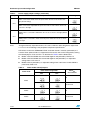
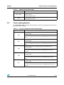
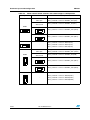
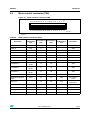
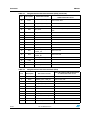
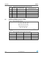
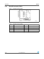
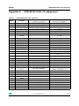
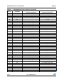
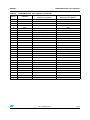
Table 21.
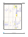
Motor control related switches and solder bridges in PGM position
PGM position
Other conditions
Description
PGM1
-
OPAMP1_IN+,OPAMP2_IN1+, OPAMP2_IN2+
pull-up source connect to +3.3V power
PG3SA position
OPAMP1_IN+, OPAMP2_IN1+, OPAMP2_IN2+
pull-up source connect to DAC_OUT1(PA4)
PGM1
PG3SA position
OPAMP1_IN+, OPAMP2_IN1+ pull-up source
connect to DAC_OUT1(PA4)
OPAMP2_IN2+ pull-up source connect to
DAC_OUT2(PA5)
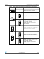
PGM2
-
OPAMP4_IN+, OPAMP4_IN1+, OPAMP4_IN2+
pull-up source connect to +3.3V power
PG3SA position
OPAMP3_IN+, OPAMP4_IN1+, OPAMP4_IN2+
pull-up source connect to DAC_OUT2(PA5)
PGM2
PG3SA position
OPAMP3_IN+ , OPAMP4_IN2+ pull-up source
connect to DAC_OUT2(PA5)
OPAMP2_IN1+ pull-up source connect to
DAC_OUT1(PA4)
Doc ID 023581 Rev 2
25/58