1
Asycube Largo A5
Operating Manual
Document
Asyril_ACUBE-LA5-01_Operating_Manual_E
Version
v1.22
Articles
ACUBE-LA5-01
Date
15.10.2015
Asycube Largo A5 - Asyril SA
Operating Manual
Introduction
v1.2
© Copyright Asyril S.A.
FO 32.03.118
Table of Contents
1.
INTRODUCTION ............................................................................................................................... 4
1.1.
GENERALITIES .......................................................................................................................... 4
1.2.
SAFETY PRECAUTIONS ............................................................................................................. 5
1.2.1. General safety precaution ................................................................................................... 5
1.2.2. Danger.................................................................................................................................... 6
2.
1.3.
W ARRANTY INFORMATION ........................................................................................................ 7
1.4.
CE INFORMATION ..................................................................................................................... 7
1.5.
RELATED MANUALS .................................................................................................................. 8
DESCRIPTION .................................................................................................................................. 9
2.1.
FIRST GLIMPSE AT THE PRODUCT............................................................................................. 9
2.2.
GENERAL CHARACTERISTICS ................................................................................................. 10
2.2.1. Technical features .............................................................................................................. 10
2.2.2. Overall dimensions ............................................................................................................. 11
2.2.3. Visual signals ...................................................................................................................... 13
2.3.
PERFORMANCE ....................................................................................................................... 14
2.3.1. Picking surface .................................................................................................................... 14
2.3.2. Displacement of the parts .................................................................................................. 14
2.4.
ELECTRICAL INTERFACES....................................................................................................... 16
2.4.1. Overview .............................................................................................................................. 16
2.4.2. Power connection ............................................................................................................... 17
2.4.3. Communication ................................................................................................................... 18
2.4.4. Backlight Synchronization ................................................................................................. 18
2.4.5. Digital input 1 and 2 ........................................................................................................... 19
2.4.6. Digital output for hoppers 1 and 2 .................................................................................... 19
2.5.
MECHANICAL INTERFACES ..................................................................................................... 20
2.5.1. Attachment of the Asycube ............................................................................................... 20
2.6.
ACCESSORIES AND OPTIONAL MODULES ............................................................................... 21
2.6.1. Additional platform .............................................................................................................. 21
2.6.2. Backlight .............................................................................................................................. 22
2.6.3. Cables .................................................................................................................................. 23
3.
TRANSPORTATION, HANDLING AND INSTALLATION ....................................................... 24
3.1.
PACKAGING OF THE PRODUCT, TRANSPORTATION AND HANDLING ....................................... 24
3.2.
BEFORE UNPACKING............................................................................................................... 24
3.3.
UNPACKING INSTRUCTIONS .................................................................................................... 25
3.4.
INSTALLATION AND STORAGE ENVIRONMENT ......................................................................... 26
3.4.1. Installation environment ..................................................................................................... 26
3.4.2. Storage environment .......................................................................................................... 26
Operating Manual
Asycube Largo A5 - Asyril SA
2/45
Asycube Largo A5 - Asyril SA
Operating Manual
Introduction
4.
v1.2
© Copyright Asyril S.A.
FO 32.03.118
MAINTENANCE AND REPARATION ......................................................................................... 27
4.1.
SAFETY PRECAUTIONS ........................................................................................................... 27
4.1.1. General safety precautions ............................................................................................... 27
4.1.2. Specific warnings ................................................................................................................ 27
4.2.
PERSONNEL RESPONSIBLE FOR MAINTENANCE OR REPARATION .......................................... 27
4.3.
MAINTENANCE ........................................................................................................................ 28
4.3.1. Periodic maintenance schedule ....................................................................................... 28
4.3.2. Remove the platform module ............................................................................................ 29
4.3.3. Control and Cleaning of the platform ............................................................................... 29
4.4.
REPARATION ........................................................................................................................... 30
4.4.1. Exchanging / installing the backlight ................................................................................ 31
4.4.2. Recover IP address using default IP address ................................................................ 36
4.5.
TECHNICAL SUPPORT ............................................................................................................. 38
4.5.1. For better service … ........................................................................................................... 38
4.5.2. Contact ................................................................................................................................. 38
5.
ANNEXES ........................................................................................................................................ 39
5.1.
CONDITION OF USE OF BACKLIGHT......................................................................................... 39
5.2.
CE CERTIFICATE .................................................................................................................... 43
Operating Manual
Asycube Largo A5 - Asyril SA
3/45
Asycube Largo A5 - Asyril SA
Operating Manual
Introduction
1.
Introduction
1.1.
Generalities
v1.2
© Copyright Asyril S.A.
FO 32.03.118
The following document is the property of Asyril S.A. and may not be copied or circulated
without permission. The information contained in this document is subject to change without
notice for the purpose of product improvement. Before operating your product, please read
this document in order to ensure a correct use of the product. Nevertheless, if you meet
difficulties during the operation or the maintenance, please, feel free to contact Asyril
customer service.
In this manual, the safety precautions that you must respect are classified as: “Danger”,
“Warning” and “Note”; the following symbols are used:
DANGER!
Failure to observe the instruction may result in serious injury.
DANGER!
Failure to observe the instruction may result in electrocution or serious injury due to
electric shock
WARNING!
Failure to observe the instruction may result in injury or property damage.
NOTE :
The user should read carefully this information to ensure the correct use of the product,
although failure to do so would not result in injury.
REFER TO …
For more information on a specific subject, the reader should read other manual, or refer to
other paragraph.
WARNING!
Asyril shall not be liable whatsoever for any loss or damage arising from a failure to observe
the items specified in “Safety Precautions.” The customer is responsible to provide the
necessary instruction to the persons concerned.
NOTE :
All dimensions in this document are expressed in millimeters
Operating Manual
Asycube Largo A5 - Asyril SA
4/45
Asycube Largo A5 - Asyril SA
Operating Manual
Introduction
1.2.
1.2.1.
v1.2
© Copyright Asyril S.A.
FO 32.03.118
Safety precautions
General safety precaution
1.2.1.1. Transport
DANGER !
Be aware of the weight and take care when transporting the system. For more
information, please refer to chapter 3 “Transportation, handling and installation”
1.2.1.2. General
DANGER !
Be sure that all power sources and other cables to the unit are disconnected before
working on the product.
DANGER !
Only qualified personnel (trained by Asyril and with professional experience) are
authorized to work on this device.
DANGER !
Do not unscrew the housing of the system controls. Serious injury or death could
result from electric shock. Only authorized personnel from Asyril SA are allowed to
access this part of the system for maintenance or for repair.
DANGER !
Do not plug or unplug cables of the system unless it is switched off.
DANGER !
Never modify the product. Unauthorized modification may cause the product to
malfunction, resulting in injury, electric shock, fire, etc.
DANGER !
Turn off the power to the product in the event of power failure. Failure to do so may
cause the product to suddenly start moving when the power is restored.
DANGER !
Do not use the product in a place where it may come in contact with water or oil
droplets.
1.2.1.3. Disposal
When the product becomes no longer usable or necessary, dispose of it properly as an
industrial waste.
WARNING!
Observe the valid legal regulation for appropriate disposal protecting environment.
Operating Manual
Asycube Largo A5 - Asyril SA
5/45
Asycube Largo A5 - Asyril SA
Operating Manual
Introduction
1.2.2.
v1.2
© Copyright Asyril S.A.
FO 32.03.118
Danger
1.2.2.1. Safety Equipment for Operators
-
For safety reasons operators must wear protective eyewear when using the backlight
NOTE :
It is the customer responsibility to install warning signs informing that anyone working around
the Asycube must wear safety equipment.
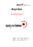
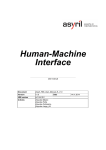
1.2.2.2. Specific danger
Backlight
The
Asycube
has
an
integrated
Backlight that persists of LED’s (Light
Emitting Diodes). These LED’s emit
visible
or
non-visible
depending
on
the
Backlight.
LED’s
radiation
color
of
the
illumination
can
create discomfort, cornea, retinal and
lens damage.
Figure 1-1 :Specific warnings
The used LED are class 0 according to the norm EN 62471, It is the responsibility of
customers to document their own application and instruct employees on procedures to limit
exposure to LED radiation. Following prevention agent can be suggested:
A. Interpose, insofar as the job allows, a high pass filter at x nm depending on the color (see
table below) under a fixed or adjustable connection between the source and the
employee
B. When the implementation of the foregoing is not possible, provide workers with goggles
or face shield suitable for blocking radiation beyond 700nm;
C. Prohibit or limit as possible direct access to the source (exposure in the axis of radiation),
see “Conditions of use of products TPL VISION” below
D. Establish a security perimeter to prevent operators from approaching the source at
distances beyond the nominal ocular hazard recommended by the manufacturer
E. In all cases, ensure that the means used properly mitigate exposure variables
(characteristics of screens or goggles to choose based on wavelength which operators
are exposed).
Refer to “5.1 Condition of use of backlight" on page 39 for the complete calculation sheet on
minimal distance to respect for each kind of backlight.
Operating Manual
Asycube Largo A5 - Asyril SA
6/45
Asycube Largo A5 - Asyril SA
Operating Manual
Introduction
v1.2
© Copyright Asyril S.A.
FO 32.03.118
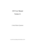
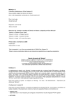
Temperature
The active elements into the asycube
make the surfaces shown on the
picture heating up to 45°C in nominal
use. This temperature can
nevertheless increase to 55°C in
extreme use.
It is the responsibility of customers to
document their own application and
instruct employees on procedures to
avoid contact with these surfaces
Figure 1-2 :Specific warnings
1.3.
Warranty information
You will find all the Asyril warranty information (duration, scope of warranty …) on the general
conditions of sale.
1.4.
CE information
The declaration of incorporation as a partly completed machinery can be found here below.
NOTE:
The partly completed machinery (Asycube) must not be put into service until the final
machinery into which it is to be incorporated has been declared in conformity with provisions
of this directive, where appropriate.
Refer to“5.2 CE Certificate" on page 43 for the complete CE Certificate of the asycube Largo.
Operating Manual
Asycube Largo A5 - Asyril SA
7/45
Asycube Largo A5 - Asyril SA
Operating Manual
Introduction
1.5.
v1.2
© Copyright Asyril S.A.
FO 32.03.118
Related manuals
As described in the Table 1-1, this manual is an integral part of the Asycube documentation
set. This manual covers the installation, a technical description, the maintenance, and the
reparation of your system. Information on the transport and safety precautions are also
included in this manual.
Manual Title
Manual reference
Description of the
content
Asycube
ACUBE-LA5-01_Unpacking_Instructions
Unpacking
Describes how to unpack
your asycube.
Instructions
Asycube Operating
ACUBE-LA5-01_Operating_Manual
THIS MANUAL
ACUBE-MEZ-FOR-LA5_User_Interface_Manual
Describes how to use the
manual
Asycube HMI
manual
HMI (simply move the
parts, and configure the
Asycube's vibrations …)
Asycube
ACUBE-LA5-01_Programming_Guide
Programming guide
Describes the way of
programming and
integrating your Asycube
in the final machine.
Asycube DLL
ACUBE-DLL_Integration_Guide
Describes the Asycube
dll's that are High-level
libraries which helps to
integrate Asycubes using
.Net 3.5 environment.
Table 1-1 : related manuals
Operating Manual
Asycube Largo A5 - Asyril SA
8/45
Asycube Largo A5 - Asyril SA
Operating Manual
Description
v1.2
2.
Description
2.1.
First glimpse at the product
© Copyright Asyril S.A.
FO 32.03.118
Asycube sets new standards in small part feeding. Its 3D vibratory platform allows fast and
flexible presentation of small parts (1 mm to 40 mm) to a robot equipped with a vision system.
The core of Asycube is a platform that can vibrate in three orthogonal directions. By selecting
appropriate vibration signals, a high flexibility in displacing parts on the platform is reached
(forward, backward, sidewise) and flipping is made possible.
It consists in :
(A)
A 3D vibrating platform (called "plate")
(B)
Electrical
interfaces
(communication,
power supply, I/Os…)
(B)
(A)
(C)
For more information on electrical
interfaces to the Asycube, please refer
to “2.4. Electrical Interfaces” on page 16
(C)
An integrated mechanism allowing to
remove the platform easily without
(D)
additional tooling
(D)
An integrated backlight (D) (optional)
that allows an easy recognition of the
parts from a camera placed above
Figure 2-1 : Asycube overview
For more information on how to remove or change the platform, please refer to ”4.3.2.
Remove the platform module” on page 29
For more information on the procedure to control the platform vibrations, please refer to the
HMI manual
For more information on the backlight color and the procedure to exchange the backlight,
please refer to “4.4.1 Exchanging / installing the backlight” on page 31
Operating Manual
Asycube Largo A5 - Asyril SA
9/45
Asycube Largo A5 - Asyril SA
Operating Manual
Description
2.2.
© Copyright Asyril S.A.
v1.2
FO 32.03.118
General Characteristics
WARNING !
Do not use the product outside the specifications. In cases of non-respectation, the product
guarantee will expire.
2.2.1.
Technical features
Asycube largo A5
Typical part size
from 2 mm to 40 mm side length
Integrated high power LED
backlight
Optional
Interchangeable backlight color
(green, red, blue, white, Infrared) please refer to
“2.6.2 Backlight” on page 22 for more information.
Independent vibrations in three
orthogonal directions
Interchangeable vibration
surface
please refer to section “2.6.1 Additional platform” on
page 21 for more information.
Vibration frequency
up to 100 Hz
configurable
Maximal weight on the platform
0.4 kg
Digital Output for hoppers
2
Digital Input
2
Analog Output
2
Operating Manual
Asycube Largo A5 - Asyril SA
10/45
Asycube Largo A5 - Asyril SA
Operating Manual
Description
2.2.2.
v1.2
© Copyright Asyril S.A.
FO 32.03.118
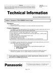
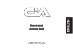
Overall dimensions
C
A
B
Figure 2-2 : overall dimensions largo A5
Characteristic
Asycube Largo A5
Footprint
Size of vibration
platform
C
171 mm
D
300 mm
F
45 mm
A
150 mm
B
195 mm
E
132 mm
Weight with platform and backlight
Operating Manual
Asycube Largo A5 - Asyril SA
7.8 kg
11/45
Asycube Largo A5 - Asyril SA
Operating Manual
Description
v1.2
© Copyright Asyril S.A.
FO 32.03.118
Additional space is needed around the Asycube to be able to remove the platform module
with the integrated tool :
147
13
Figure 2-3 : overall dimensions with "lever"
Refer to “4.3.2 Remove the platform module” on page 29 for more information on how to
remove the platform :
Operating Manual
Asycube Largo A5 - Asyril SA
12/45
Asycube Largo A5 - Asyril SA
Operating Manual
Description
2.2.3.
© Copyright Asyril S.A.
v1.2
FO 32.03.118
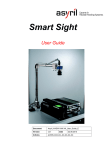
Visual signals
The led give important information on
the state of the Asycube :
Led
State
Meaning
Blinking
System in
”ton”
standby
100ms
(1)
1
(2) (3)
(4)
(5)
(6)
(7)
(8)
Blinking
“ton”
System in service
900ms
2
On
3
On
24V on S-Power
input
24V on Power
input
Communication
4
Blinking
(Send/Receive
TCP packet)
24V on backlight
5
On
(9)
synchronization
(10)
input
6
On
24V on input 1
7
On
24V on input 2
8
On
Platform vibrating
9
On
24V on output 1
10
On
24V on output 2
Operating Manual
Figure 2-4 : Asycube Operating Indicator LED’s
Asycube Largo A5 - Asyril SA
13/45
Asycube Largo A5 - Asyril SA
Operating Manual
Description
v1.2
2.3.
Performance
2.3.1.
Picking surface
The
maximum
dimensions
picking
corresponds
© Copyright Asyril S.A.
FO 32.03.118
surface
to
the
Asycube platform size :
A
195
B
150
B
A
Figure 2-5 : Picking surface
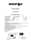
2.3.2.
Displacement of the parts
2.3.2.1. Standard movement
To define a specific movement with
the Asycube several parameters need
to be configured. For each movement
on the cube, twelve parameters must
be
set.
Calling
parameters
will
these
twelve
generate
specific
vibrations (corresponding to the sum
of
the
movements
of
the
four
actuators in each corner of the
platform).
Figure 2-6 : predefined displacement of the parts
The figure on the right shows the
predefined standard movements.
Operating Manual
Asycube Largo A5 - Asyril SA
14/45
Asycube Largo A5 - Asyril SA
Operating Manual
Description
v1.2
© Copyright Asyril S.A.
FO 32.03.118
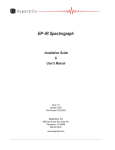
2.3.2.2. Advanced movement
On the Asycube Largo A5, advanced
movements can be achieved. Indeed,
it
is
possible
to
center
components along the long
the
side or
the short side of the plate, as
represented on the figure on the right.
With a sequence of three movements
you can spread easily the parts on the
surface :
1. Center (long side)
2. Center (short side)
3. Flip
Figure 2-7 : predefined displacement of the parts
For more information on these parameters, and to learn how to configure them, in order to
control the cube vibrations, please refer to the User manual
Operating Manual
Asycube Largo A5 - Asyril SA
15/45
Asycube Largo A5 - Asyril SA
Operating Manual
Description
2.4.
2.4.1.
© Copyright Asyril S.A.
v1.2
FO 32.03.118
Electrical Interfaces
Overview
Asycube is a standalone module with
its
own
controler.
The
electrical
(A)
(B)
(C) (D)
(E)
interfaces to the Asycube are situated
at the back of the product:
(A)
Power connection
(B)
Ethernet connection (RJ45)
(C)
Backlight synchronization
(D)
Digital Input 1
(E)
Digital Input 2
(F)
Digital and analog Output 1 for
hopper
(G)
Digital and analog Output 2 for
(F)
hopper
(G)
Figure 2-8 : Electrical interfaces to the Asycube
NOTE :
The cables are not part of the feeder,
but can be ordered separately.
(Please,
refer
to
chapter
2.6.3
"Cables")
Operating Manual
Asycube Largo A5 - Asyril SA
16/45
Asycube Largo A5 - Asyril SA
Operating Manual
Description
2.4.2.
v1.2
© Copyright Asyril S.A.
FO 32.03.118
Power connection
WARNING !
-
Before supplying power to the Asycube, check that your distribution voltage is the same
as the nominal voltage.
-
Never disconnect the power cables. Always turn the machine off and then cut the power
-
Use PELV (protected extra-low voltage) nominal voltage
Pin
Signal description
(1)
24VDC PELV
(1)
(2)
S-Power
(5)
(4)
(3)
(2)
0V GND S-Power
(3)
24VDC PELV
Power
(4)
0V GND Power
(5)
EARTH
Connector type (on asycube side) :
M16, 5 Poles, male
In case of all functions working
Figure 2-9 : power connection
simultaneously (vibration, backlight,
outputs), the current increases to 8A.
Characteristic
Value
Voltage
+24V DC + 5%
Current Power
5A
Current S-Power
3A
WARNING !
-
S-Power is the safety power. This 24V is the power supply of backlight and digital
outputs. Cutting this 24V permits to be sure that the backlight and the outputs
stay OFF (e.g. to secure IR backlight danger). As a consequence, you must get a
24V signal on the S-Power to be able to use the backlight.
Operating Manual
Asycube Largo A5 - Asyril SA
17/45
Asycube Largo A5 - Asyril SA
Operating Manual
Description
2.4.3.
v1.2
© Copyright Asyril S.A.
FO 32.03.118
Communication
The communication with the asycube is
established
by
a
standard
Ethernet
communication via RJ45 port (A)
Characteristic
Default IP
address
Default subnet
mask
Value
192.168.127.254
255.255.255.0
Port
4001
MAC address
Can be read by
ARP request
(A)
For more information on the procedure to
restore the default IP address, please see
Figure 2-10 : Ethernet connection RJ45
chapter 4.4.2.
2.4.4.
Backlight Synchronization
A standard M8 three-pins female cable
enables to synchronize camera acquisition
(3)
and Asycube backlight illumination, it must
(1)
(4)
be connected as follows :
Pin
Signal
(1)
Not wired
(3)
0V GND
(4)
+24 V pulse
(illumination synch.)
Connector type (on asycube side) :
M8, 3P, male
Figure 2-11 : Backlight synchronization
NOTE :
The Asycube Backlight illumination time corresponds to the length of the pulse signal.
Operating Manual
Asycube Largo A5 - Asyril SA
18/45
Asycube Largo A5 - Asyril SA
Operating Manual
Description
2.4.5.
v1.2
© Copyright Asyril S.A.
FO 32.03.118
Digital input 1 and 2
A standard M8 three-pins male cable
enables to read two different signal , it
(1)
must be connected as follows :
Pin
Signal
(1)
+24VDC
OUT
(3)
(4)
(sensor
power supply)
(3)
0V GND
(4)
Input (+24VDC)
Connector type (on asycube side) :
M8, 3P, female
Figure 2-12 : Digital input
2.4.6.
Digital output for hoppers 1 and 2
A standard M8 four-pins male cable
enables to transmit digital output signal
and analog output signal to hopper. It
(1)
(2)
(3)
(4)
must be connected as follows :
Pin
Signal
(1)
0V GND
(2)
0…10VDC
(3)
0V GND
(4)
+24VDC
Hopper
Analog Output 1
Digital Output 1
Connector type (on asycube side) :
M8, 4P, female
Figure 2-13 : Digital output for hoppers
Operating Manual
Asycube Largo A5 - Asyril SA
19/45
Asycube Largo A5 - Asyril SA
Operating Manual
Description
2.5.
2.5.1.
v1.2
© Copyright Asyril S.A.
FO 32.03.118
Mechanical Interfaces
Attachment of the Asycube
To guarantee a proper behavior of the Asycube a tight fastening to a solid underground is
necessary. The holes in the base plate of the Asycube can be used to attach it with four M6
screws.
Repeatable positioning of the Asycube can be done by using positioning pins (possible on
both sides).
Figure 2-14 : attachment of the Asycube
Operating Manual
Asycube Largo A5 - Asyril SA
20/45
Asycube Largo A5 - Asyril SA
Operating Manual
Description
2.6.
2.6.1.
© Copyright Asyril S.A.
v1.2
FO 32.03.118
Accessories and Optional modules
Additional platform
In order to improve the availability of certain components on the surface of the feeder, it is
possible to structure the plate surface. Asyril can provide various types of plates on request.
Frequently used structures on Asycube Largo A5 are as follows:
Plate
type
Example – picture
Example – drawing
Advantage
Plane
This type of plate can be used for a
large variety of components mainly
components with a flat surface
allowing a stable resting position.
Ex : Bolts
Grooves
(deep)
Screw type components can be fed in
vertical position when the plate is
structured with deep grooves.
Ex : Screws, Rivets
Grooves
Wide grooves are useful when
(wide)
cylindrical components are fed. They
reduce the stabilising time significantly
after component displacements on the
plate surface (stop the components
from rolling on the surface).
Ex : Cylinders, Needles
Grooves
Narrow grooves are necessary to
(narrow)
reduce surface contact especially for
flat and light components. This
reduces adhesion forces and improves
the component displacements on the
feeder surface. It also improves the
Ex : Thin washers
Operating Manual
Asycube Largo A5 - Asyril SA
pick-performance of the robot.
21/45
Asycube Largo A5 - Asyril SA
Operating Manual
Description
© Copyright Asyril S.A.
v1.2
FO 32.03.118
Holes
Holes are useful when cylindrical
components are to be fed and
presented upright.
Ex : Pins
NOTE :
For more information on these bespoke platforms, contact Asyril customer’s service.
The table below indicates the article number of a standard (not structured platform)
Product
Part number
Asycube standard platform
Y 660 005 776
(not structured)
2.6.2.
Backlight
Following backlight are available:
Product
Part Number
Backlight Blue, wavelength 465 nm
Y 900 006 095
Backlight Green, wavelength 550 nm
Y 900 006 093
Backlight Infrared, wavelength 850 nm
Y 900 006 097
Backlight Red, wavelength 645 nm
Y 900 006 094
Backlight White, 6500 K
Y 900 006 096
If this option is ordered at the same time with the asycube, it is delivered mounted in the
feeder
For more information on the backlight color and the procedure to exchange the backlight,
please refer to “4.4.1 Exchanging / installing the backlight” on page 31
NOTE :
For more information on these bespoke backlights, contact Asyril customer’s service.
Operating Manual
Asycube Largo A5 - Asyril SA
22/45
Asycube Largo A5 - Asyril SA
Operating Manual
Description
2.6.3.
v1.2
© Copyright Asyril S.A.
FO 32.03.118
Cables
Following cables are available:
Product
Part Number
Power cable (5m)
Y 900 006 215
Ethernet RJ45 cable (5m)
Y 601 000 218
Synchro-backlight cable (5m)
Y 900 006 223
Input Cable (5m)
Y 900 006 224
Output cable (5m)
Y 900 006 225
NOTE :
For more information on these cables, contact Asyril customer’s service.
WARNING :
All these cables are NOT adapted for cable carriers (cable tracks).
Operating Manual
Asycube Largo A5 - Asyril SA
23/45
Asycube Largo A5 - Asyril SA
Operating Manual
Transportation, handling and installation
© Copyright Asyril S.A.
v1.2
FO 32.03.118
3.
Transportation, handling and installation
3.1.
Packaging of the product, transportation and handling
The transportation of the product must be made in accordance with the specific terms
indicated on the package (top, bottom and fragile …). In addition, pay particular attention to
the following points :
WARNING !
-
Be aware of the weight and take care when transporting the system.
-
Always hold the system firmly with two hands on the side bars.
-
The operator should not carry heavy shipping boxes by himself.
-
If the shipping box is to be left standing, it should be in a horizontal position.
-
Do not climb on the shipping box.
-
Do not place heavy objects, on top of the shipping box.
The Asycube is shipped in a cardboard of the following dimensions:
Largo A5
Dimensions
550x400x300 mm
Gross weight
12 kg
Table 3-1 : gross weight and dimensions of the product when packaged
3.2.
Before unpacking
Before unpacking, look at the ShockWatch Label. As to promote zero-defect shipping, all
Asyril products are shipped with a ShockWatch Label. If this is red, or if any evidence of
damage during transit was to be indicated please :
(A)
request that the carrier’s agent be present at the time of
unpacking.
(B)
pay special attention to any damage on the exteriors of the product
(C)
If any damage has occurred, do not sign the delivery recipit and
contact Asyril
(D)
In every cases, make a notation on the delivery recipit
Figure 3-1 : ShockWatch
NOTE :
If the items received do not match to your order, or are damaged, do not sign the receipt,
and contact Asyril as soon as possible.
Operating Manual
Asycube Largo A5 - Asyril SA
24/45
Asycube Largo A5 - Asyril SA
Operating Manual
Transportation, handling and installation
3.3.
v1.2
© Copyright Asyril S.A.
FO 32.03.118
Unpacking instructions
NOTE
Do not remove the Asycube from its packaging until you are ready to install it.
WARNING !
Keep the packaging material and the shipment box in case of return
Locate the identification sticker at
the back of the product and ensure
that the product you have received is
Asyril SA – Switzerland
www.asyril.ch
Adrticle N0 : xxx xxx xxx
the appropriate one.
Type: ACUBE-LA5
Important information is on this
sticker;
such
as
the
power
Input voltage 24VDC
Serial N0: xxxxxx
consumption or the serial number
that you will need for any kind of
correspondence with Asyril.
Figure 3-2 : Product sticker
The product key gives the product designation as follows:
ACUBE - LA5 - xx - - yy - 01 - 03 -
02
Version
01 – Version
number
Backlight
00 – no backlight
01 – green
02 – red
04 – blue
05 – white
06 – infrared
Figure 3-3 : product key
Operating Manual
Asycube Largo A5 - Asyril SA
25/45
Asycube Largo A5 - Asyril SA
Operating Manual
Transportation, handling and installation
3.4.
v1.2
© Copyright Asyril S.A.
FO 32.03.118
Installation and storage environment
WARNING !
The Asycube must be mounted on a smooth, flat and strong surface. Ensure yourself
that the Asycube is not submitted to mounting flexure. Failure to do so would degrade
feeder performance.
3.4.1. Installation environment
The Asycube can be used under following conditions:
-
The asycube is IP20
-
Working temperature: +5°C to +40°C
-
Humidity: 30% to 80%max. non-condensing
WARNING !
In the case humidity or temperature variation, note that it might affect the global
performances of the Asycube.
-
Avoid extreme electromagnetic waves, ultraviolet rays and radiation.
-
Avoid using the product in a place where the main unit or controller may be exposed to water
or oil droplets.
-
Clean room application: cleanliness class ISO7
WARNING !
Do not use the product in an atmosphere of corrosive gases. Rust may form and reduce
the structural strength of the product.
3.4.2. Storage environment
The storage environment should be similar to the operating environment. In addition, you
should protect the Asycube against dust
Operating Manual
Asycube Largo A5 - Asyril SA
26/45
Asycube Largo A5 - Asyril SA
Operating Manual
Maintenance and reparation
v1.2
4.
Maintenance and reparation
4.1.
Safety precautions
4.1.1.
© Copyright Asyril S.A.
FO 32.03.118
General safety precautions
WARNING !
There are no user serviceable parts inside the product. Contact Asyril or your local
supplier to effect maintenance. In cases of non respectation, the product guarantee will
expire.
DANGER !
Do not operate the system when it is damaged. Please ensure yourself before use
that no visual defects are detected.
DANGER !
Power down the system and unplug it from the mains before any kind of
maintenance.
DANGER !
Do not pour water onto the product. Spraying water over the product, washing it
with water or using it in water may cause the product to malfunction, resulting in
injury, electric shock, fire, etc.
4.1.2.
Specific warnings
WARNING !
Be sure that the platform is unloaded before any kind of maintenance.
4.2.
Personnel responsible for maintenance or reparation
Maintenance operation must be done by personnel who has a working knowledge of the
system, nevertheless, we can define three kind of staff :
(A)
Maintenance technician without any specific formation from Asyril
(B)
Maintenance technician with a specific formation from Asyril
(C)
Technician from Asyril’s customer service
Make sure that the person who will be working on the maintenance has received and read
this manual, and will be able to work in the manner specified in the following sections. All
personnel must observe the safety precautions listed in this manual.
Operating Manual
Asycube Largo A5 - Asyril SA
27/45
Asycube Largo A5 - Asyril SA
Operating Manual
Maintenance and reparation
4.3.
© Copyright Asyril S.A.
v1.2
FO 32.03.118
Maintenance
WARNING !
For any kind of maintenance, always use Asyril products.
4.3.1.
Periodic maintenance schedule
Our Asycube are largely maintenance-free, however, simple inspections should be done at
regular intervals to ensure optimum performances, and safety operating of your product.
Item
General
Period
Reference
Cleaning of the machine
Week
Visual check of electrical harness
Year
Visual check and cleaning of the plate
Week
Section 4.3.3
/
/
specific
It is the customer’s responsibility to schedule
process
the maintenance of his specific process
Backlight
Visual check
Month
Table 4-1 : periodic maintenance schedule
NOTE :
The information given in the “Table 4-1 : periodic maintenance schedule” is only
informative, maintenance and times must be modified by the operator in accordance
with your particular system, its operating environment and the amount of usage.
Operating Manual
Asycube Largo A5 - Asyril SA
28/45
Asycube Largo A5 - Asyril SA
Operating Manual
Maintenance and reparation
4.3.2.
v1.2
© Copyright Asyril S.A.
FO 32.03.118
Remove the platform module
DANGER !
Be sure that the backlight is off
before
removing
the
(B)
platform
(A)
module.
Risk of crushing. Do not place
your finger between the platform
and the locking mechanism
(C)
(B)
Pull out the integrated tool (A) and
Step 1
move it away for freeing the
platform (B)
Take the platform out (C)
Step 2
Release the tool – the mechanism
as reverse operation from step 1 to
let it goes to its initial position
Figure 4-1 : remove the platform
4.3.3.
Control and Cleaning of the platform
Material needed :
Step 1
-
Lint-free cloth
-
isopropanol alcohol
(A)
Control the surface state of the
platform (A) and be particularly
careful to the following points :
-
Big claws
-
Dirt or spotted surface
-
Oily or greasy surface
Figure 4-2 : Platform
WARNING :
If the surface is damaged so as to
obstruct vision or the behavior of
parts, its replacement must be
proceeded
Step 2
Clean the surface of the platform
Operating Manual
Asycube Largo A5 - Asyril SA
29/45
Asycube Largo A5 - Asyril SA
Operating Manual
Maintenance and reparation
4.4.
v1.2
© Copyright Asyril S.A.
FO 32.03.118
Reparation
This section gives a list of the replaceable parts in the system with their part numbers. The
product must be returned to the manufacturer for any repair work. In exceptional cases, and
after acceptation of Asyril S.A. this work can be performed on the costumer’s site by trained
personnel as defined in section 4.2.
WARNING !
For any kind of reparation, always use Asyril products.
Two kind of parts are defined :
(A)
Part way that might be changed after 1 year (wear part)
(B)
Part way that might be changed after 5 years
Part name
Type
Part Number
Backlight assembly Blue
B
Y 900 006 107
Backlight assembly Green
B
Y 900 006 106
Backlight assembly Infrared
B
Y 900 006 109
Backlight assembly Red
B
Y 900 006 105
Backlight assembly White
B
Y 900 006 108
Asycube platform
A
Y 660 005 776
Table 4-2 : Replaceable parts
Operating Manual
Asycube Largo A5 - Asyril SA
30/45
Asycube Largo A5 - Asyril SA
Operating Manual
Maintenance and reparation
4.4.1.
© Copyright Asyril S.A.
v1.2
FO 32.03.118
Exchanging / installing the backlight
DANGER !
Be sure that all power sources and other cables to the unit are disconnected before
changing the backlight.
Material needed :
-
New backlight assembly ordered from asyril
-
Flat wrench size 5.5
-
Torx key size 10
Step 1
Unscrew the 7 screws on
both sides (A) and (A') and
(A')
remove the two side covers
Use an torx key size 10
(A)
Step 2
On both sides, unscrew the
four bolts (B)
Use a flat wrench size 5.5
(B)
Operating Manual
Asycube Largo A5 - Asyril SA
31/45
Asycube Largo A5 - Asyril SA
Operating Manual
Maintenance and reparation
v1.2
© Copyright Asyril S.A.
FO 32.03.118
Step 3
Unplug the backlight
(C)
connector (C)
Remove the old backlight (D)
and insert the new backlight
(E)
(D)
(E)
Operating Manual
Asycube Largo A5 - Asyril SA
32/45
Asycube Largo A5 - Asyril SA
Operating Manual
Maintenance and reparation
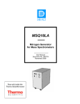
Step 5
© Copyright Asyril S.A.
v1.2
FO 32.03.118
Align the backlight module
flush with the mirror support
(F) and tighten the four
bolts (G)
Use a flat wrench size 5.5
(G)
(F)
Step 6
Plug the backlight connector
(H)
(H)
Step 7
Remount the covers (I) and
(I') on both sides
(I')
(I)
Operating Manual
Asycube Largo A5 - Asyril SA
33/45
Asycube Largo A5 - Asyril SA
Operating Manual
Maintenance and reparation
v1.2
© Copyright Asyril S.A.
FO 32.03.118
4.4.1.1. Configure the Asycube with a new backlight color
You can set the color of the backlight in the Asycube. It is useful for example to be able to
adapt interfaces depending of the color or depending if there is no backlight.
With HMI
To modify the parameter, use the following procedure:
(B)
(A)
(C)
Figure 4-3 : change backlight color in HMI
Ref.
Designation
Description
(A)
"Asycube" button
Press this button to display the Asycube screen.
(B)
"Asycube
configuration"
button
Press this button to display the Asycube configuration tab.
(C)
“Color” select box
This select box allows selecting the color of the backlight.
If “None” is chosen, backlight tab and backlight switches
disappear.
For more information about the HMI, please refer to the user interface documentation.
With dll
To modify the parameter with dll, use this function:
SetBacklightColor(BacklightColor color, string password)
The password is important, because to write this parameter, you need to be logged in the
firmware as Integrator. Password is 1234.
For more information on the DLL, please refer to the user guide documentation.
Operating Manual
Asycube Largo A5 - Asyril SA
34/45
Asycube Largo A5 - Asyril SA
Operating Manual
Maintenance and reparation
v1.2
© Copyright Asyril S.A.
FO 32.03.118
Using tcp commands
To modify the parameter with TCP commands, use this sequence of commands:
1
Command
Function
{#1,wp7=1234}
Login in integrator mode
More informations
0: Green
1: Red
2: Blue
2
{#1,wp97=1}
Write color of backlight
3: IR
4: UV
5: White
99: None
3
{#1,df}
Save configuration in flash memory
4
{#1,wp7=1}
Logout
Operating Manual
Asycube Largo A5 - Asyril SA
35/45
Asycube Largo A5 - Asyril SA
Operating Manual
Maintenance and reparation
4.4.2.
v1.2
© Copyright Asyril S.A.
FO 32.03.118
Recover IP address using default IP address
The following procedure explains how to reboot the Asycube on the default IP address,
subnet mask and tcp port number to be able to modify IP address, subnet mask and tcp port
number when they are unknown and cannot be founded. Following this procedure, you are
able to connect on the Asycube with default parameters and then modify unknown
parameters.
Step 1
Unscrew the 3 screws on
both sides (A) and remove
the cover
(A)
Use an torx key size 10
Step 2
Place selector 1 in "off"
position (B)
1 2 3 4
(B)
Step 3
Disconnect and reconnect the power cable (or switch off and switch on the
power on the Asycube).
The AsyCube will take default parameters at startup :
IP: 192.168.127.254
SubnetMask: 255.255.255.0
TCP Port: 4001
Operating Manual
Asycube Largo A5 - Asyril SA
36/45
Asycube Largo A5 - Asyril SA
Operating Manual
Maintenance and reparation
Step 4
© Copyright Asyril S.A.
v1.2
FO 32.03.118
Parameters in memory can now be modified (by direct access with commands to the
AsyCube, by functions in dll or by Asycube configuration page in HMI (see relative
documentations for more details).
Step 5
When parameters are defined as
desired, replace selector 1 in
position ( C).
1 2 3 4
(C)
Step 6
Disconnect and reconnect the power cable (or switch off and switch on the power on
the Asycube).
The Asycube will take parameters defined at startup.
Step 7
Replace the cover and screw the
3 screws on both sides (A)
Use an torx key size 10
Operating Manual
Asycube Largo A5 - Asyril SA
(A)
37/45
Asycube Largo A5 - Asyril SA
Operating Manual
Maintenance and reparation
4.5.
4.5.1.
v1.2
© Copyright Asyril S.A.
FO 32.03.118
Technical support
For better service …
You have read the related manuals without finding answers to your questions ? Before calling
the support service, note the following information for your system:
4.5.2.
-
serial number and product key of your material
-
software version
-
alarm or error message displayed on the screen
Contact
You can find lot of information on our website : www.asyril.ch
You can also contact us by mail or through our web-site contact form :
[email protected]
+41 26 653 7190
Operating Manual
Asycube Largo A5 - Asyril SA
38/45
Asycube Largo A5 - Asyril SA
Operating Manual
Annexes
v1.2
5.
Annexes
5.1.
Condition of use of backlight
Operating Manual
Asycube Largo A5 - Asyril SA
© Copyright Asyril S.A.
FO 32.03.118
39/45
Asycube Largo A5 - Asyril SA
Operating Manual
Annexes
Operating Manual
v1.2
Asycube Largo A5 - Asyril SA
© Copyright Asyril S.A.
FO 32.03.118
40/45
Asycube Largo A5 - Asyril SA
Operating Manual
Annexes
Operating Manual
v1.2
Asycube Largo A5 - Asyril SA
© Copyright Asyril S.A.
FO 32.03.118
41/45
Asycube Largo A5 - Asyril SA
Operating Manual
Annexes
Operating Manual
v1.2
Asycube Largo A5 - Asyril SA
© Copyright Asyril S.A.
FO 32.03.118
42/45
Asycube Largo A5 - Asyril SA
Operating Manual
Annexes
v1.2
© Copyright Asyril S.A.
FO 32.03.118
5.2. CE Certificate
Operating Manual
Asycube Largo A5 - Asyril SA
43/45
Asycube Largo A5 - Asyril SA
Operating Manual
Annexes
v1.2
© Copyright Asyril S.A.
FO 32.03.118
Review history
Rev.
Date
Author
Comments
1.0
03.10.2014
BeJ
Initial Version
1.1
06.11.2014
BeJ
Pt 2.4.2 TBTP modified in PELV, pt 1.4 CE certification
1.2
23.04.2015
HsJ
Changes for pinout connectors and power max current.
1.21
16.06.2015
HsJ
Remove 5V TTL synchro backlight, because it’s not
guaranteed.
1.22
15.10.15
Operating Manual
BeJ
§2.6.3: “cables not adapted for cable tracks” added
Asycube Largo A5 - Asyril SA
44/45
This document is the property of Asyril S.A. and may not be copied or circulated without
permission. The information contained in this document is subject to change without notice for
the purpose of product improvement.
asyril sa
z.i. le vivier
ch-1690 villaz-st-pierre
switzerland
tel. +41 26 653 71 90
fax +41 26 653 71 91
[email protected]
www.asyril.ch