1
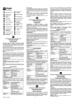
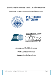
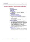
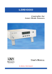
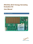
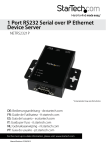
High Performance Transceiver for Sub 1-Ghz Applications SPIRIT1 SPIRIT1 application focus HOME/BUILDING AUTOMATION SMART METERING WIRELESS SENSOR NETWORKS ALARM SYSTEMS INDUSTRIAL MONITORING & CONTROL SPIRIT1 – Product presentation 31/01/2013 2 SPIRIT1: Best in class transceiver ENTERING THE MARKET WITH BEST IN CLASS SOLUTION Cuts power budget up to 50% over competing devices Design focused on Power Savings • RX 9 mA • TX 21 mA (+11 dBm) • Shutdown 2.5 nA Excellent Sensitivity -120 dBm Presentation Title 31/01/2013 3 SPIRIT1: Description 4 • Frequency bands: 169, 315, 433, 868, 915, 920 MHz • Configurable data rate from 1 to 500 kbps • SPI interface • Supply voltage: 1.8 V to 3.6V QFN20 4x4 (thickness 0.9mm) • Modulation schemes: 2-FSK, GFSK, MSK, GMSK, OOK, and ASK Available NOW • Suitable for Systems targeting compliance • Wireless MBUS standard • ETSI EN 300 220, FCC CFR47 Part 15, ARIB STD-67 4 SPIRIT1: Key Features 5 • Output Power: -36 dBm to +11 dBm, in 0.5 dB steps • Excellent receiver sensitivity: - 120 dBm (1.2 kbps – 169MHz) • Adjacent channel selectivity : 55 dB at 12.5 kHz channel spacing (1% PER – 20 bytes packet length) • Integrated SMPS allows very low power consumption Shutdown Mode 2.5 nA Everything OFF RX 9 mA SPI on, XTAL on, Synth on TX 21 mA SPI on, XTAL on, Synth on Standby Mode 650 nA SPI on, register retention Sleep 950 nA SPI on, register retention, RC oscillator 5 COMP. C SPIRIT1 34mA 17mA 10mA 0dBm 9mA 0dBm TX Current consumption cut >28% @ max o/p power 20mA +11dBm 21mA 43% 29mA +11dBm 37mA +11dBm COMP. B 28% COMP. A TX current SPIRIT1 +11dBm -105dBm COMP. A COMP. B 0dBm 13mA - RX Current consumption cut >30% - Sensitivity performances are not sacrificed 0dBm 9mA 16mA 60% -110dBm SENSITIVITY 22mA 30% RX CURRENT SPIRIT1: Operation lifetime increases COMP. C SPIRIT1 – Product presentation 31/01/2013 6 SPIRIT1: Key Features 7 • Integrated packet handler • Support for automatic acknowledgment, retransmission, low duty cycle protocol and timeout protocol • Automatic clear channel assessment (CCA) engine • Channel access mechanism, based on the rule ‘’Listen-before-talk’’ systems. Embedded CSMA/CA protocol • Fully integrated ultra low power RC oscillator • AES 128-bit encryption co-processor for secure data transfer 7 SPIRIT1: Key Features 8 • Frequency Hopping under MCU control • Calibration can be made each time the MCU decide to change frequency or MCU can save and restore calibration data to make the frequency hopping faster • Separate 96-byte RX/TX FIFOs • accessible via the SPI interface for host processing • Supports automatic antenna selection through an integrated antenna diversity switching mechanism • Programmable RX digital filter from 6 kHz to 800 kHz 8 SPIRIT1 Block Diagram 9 LNA ADC FREQ SYNTH 90 TX MODULATOR 0 PA GPIO INTERFACE GPIO_0 GPIO_1 GPIO_2 GPIO_3 CSn SCLK SDI SDO SPI RXn RX FIFOs RXp TX FIFOs ADC DATA LINK LAYER DEMODULATOR ATB RADIO CONTROL AES 1/2 RM ADC LDO Digital LDO PROG LDO OUTDiv LDO SMPS VDD SMPS XIN XOUT VR DIG SMPS Ext2 XO BOR POR (raw) SMPS Ext1 Low Power Digital LDO VDD DIG SDN RCO LoopDiv LDO DIG I/O LDO 1V5 PLL LDO BOR (acc) REGISTERS MAP VCO LDO CENTRAL BIAS DIGITAL CLOCK BLD 1/2 TEMP SENS 1/2 GND PA 9 Main Block Description • Receiver • Architecture based on LOW IF conversion • The received RF signal is amplified by a two-stage low noise amplifier (LNA) and downconverted in quadrature (I and Q) to the intermediate frequency (IF). At IF, the I/Q signals are digitized by high dynamic range ADCs. • The Demodulator data is then provided to an external MCU either through the 96-byte RX FIFO, readable via SPI, or via a GPIO pin. • Transmitter • Architecture is based on direct synthesis of the RF frequency • The data to be transmitted are provided by an external MCU either through the 96-byte TX FIFO writable via SPI, or directly using a programmable GPIO pin • Power Management • Integrates a high efficiency step-down converter (SMPS) cascaded with LDOs to supply both analog and digital parts. • Operates from a battery voltage ranging from 1.8 V to 3.6V, with high power efficiency 10 Main Block Description • Clock Signal : External crystal • An external 24, 25, 26, 48, 50 or 52 MHz Crystal (between XIN and XOUT) or an external clock signal can be used • An integrated low-power RC oscillator, generating the 34.7 kHz signal is used as a clock for the slowest timeouts (i.e low duty cycle protocol or CSMA/CA protocol) • Digital Interface • A 4-wire SPI serial interface is used to communicate with the external MCU. • 4 GPIOs that can be registered through the SPI registers to perform various functions, including • • • • • • • • MCU clock output FIFO status flags Wake-up input Battery level detector TX-RX external switch control Antenna diversity control Temperature sensor output Interrupts 11 Main Block Description • Data link layer • Support for channel configuration, packet handling and data buffering • Support Packet Formats (Basic, STack and Wireless M-BUS ) • The Host MCU can stay in power down until a valid RF packet has been received, and then burst read the data, greatly reducing the power consumption and computing power required from the host MCU • AES encryption co-processor • Provides data security support as it embeds an advanced encryption standard (AES128) core which implements a cryptographic algorithm • Analog temperature sensor • The Host MCU can be used to read the chip temperature (e.g. it can be used to force radio recalibration) • Battery indicator and low battery detector 12 Product Status & Material 13 • Product RTM with All Documentation available on http://www.st.com/internet/imag_video/product/253167.jsp • Application Notes, Schematics, BOM, Gerber Files • SW Development Kit (SDK) for STM32L, includes WM-Bus library, Set of examples Application Notes Presentation Title 31/01/2013 14 Development Kits • SPIRIT1 Development Kits • • • • • • STEVAL-IKR001V1 – 169 MHz STEVAL-IKR001V2 – 315 MHz STEVAL-IKR001V3 – 433 MHz STEVAL-IKR001V4 – 868MHz STEVAL-IKR001V5 – 915 MHz STEVAL-IKR001V6 – 920 MHz • Development kit content • • • • • 2 x STM32L based motherboard 2 x SPIRIT1 RF modules 2 x Antennas 2 x USB cables Software development kit (SDK) has to be downloaded from http://www.st.com • Includes ST Wireless MBUS stack, Examples, Documentation • Kit boards are preprogrammed with a firmware for GUI evaluation (DFU for firmware upgrade over USB) Presentation Title 31/01/2013 15 SPIRIT1: Summary 16 • Multi Band Transceiver, Targeting the Following Applications : • • • • Wireless Metering and Wireless Smart Grid Home & Building Automation Industrial Monitoring and Control Wireless Fire and Security Alarms • Best in Class Solution in Power Saving : Cuts power budget by 30% over competing devices • Excellent RF performances : High Sensitivity, High Selectivity, Antenna Diversity ensuring reliability & robustness performances • Compliant Wireless MBus standard • Demo Kit @ All frequency Band available NOW • Product in Mass Production 16 Technical Details Transmission & Reception RF Related Features – Packet Handler Engine - MCU Interface & Others Development Kit (HW, SW, SDK Suite) Transmission & Reception RF Related Features SPIRIT1 Oscillator and RF synthesizer • An external XTAL (24, 25, 26, 48, 50, 52 MHz), provide a clock signal to the frequency synthesizer. • The digital macro always requires clock in the range (24-26 MHz), so the clock must be divided when using 48-52 MHz XTAL. • RF synth has fractional sigma delta architecture for fast settling and narrow channel spacing. • It uses a multi-band VCO to cover the whole frequency range. • The frequency is programmed using SYNT0-SYNT3 registers of SPIRIT1 (easiest way is to use SPIRIT1 SW library) • Calibration can be automatic (80 us) or manual (20 us), in the latter case the micro should save/restore the calibration words and take into account for temperature/VBAT variation which could require recalibration. 19 Receiver Quality Indicators • Received signal strength indicator (RSSI) - Measured received signal power. RSSI reading is available after the reception of a packet in a register • Carrier Sense (CS) – based on RSSI (threshold, static/dynamic mode) • Link quality indicator (LQI) – level of noise power on the demodulated signal • Preamble quality indicator (PQI) - the reliability of the preamble detections • Preamble valid IRQ can be used • Packet demodulation can be stopped when PQI is below threshold • Synchronization quality indicator (SQI) - measurement of the best correlation between the received synchronization word and the expected one • Sync word detected IRQ • Packet demodulation can be stopped when SQI is below threshold 20 Transmission & Reception Packet handler Engine SPIRIT1 Packet Handler Engine Embedded packet format: • STack Preamble Sync Length Destination Address Sync Payload Postamble Source Address Control Seq. No. Control Payload CRC • WM-Bus Preamble • BASIC Preamble Sync Length Destination Address No ACK Payload CRC 22 SPIRIT1 Direct mode The purpose of the direct modes are to by-pass completely the packet handler engine and to give the user more flexibility. The direct modes are available both for RX and TX. • Direct mode through FIFO (SPI) • In the direct mode through FIFO the data are continuously read from the TX FIFO and transmitted without any processing of the packet handler for the transmitter and the data are continuously received in the RX FIFO without any processing. • Direct mode through GPIO • In the direct mode through GPIO the data are sampled by the device on the rising edge of the clock signal and send on air without any processing of the packet handler for the transmitter and the data are continuously written to one GPIO together with the clock in another GPIO. • PN9 mode (for TX) • A pseudo-random binary sequence is generated internally for test purpose only. 23 SPIRIT1 Automatic Packet Filtering Embedded automatic packet filtering • CRC (Packet discarded if CRC check do not pass) • Destination address (My own address, Broadcast, Multicast) • Source address (reference one in AND bitwise with the source mask) • Control field (reference one in AND bitwise with the control mask) • The automatic packet filtering engine works only in STack and BASIC packet format. • More than one automatic filtering feature can be enabled at the same time. 24 SPIRIT1 Link Layer Protocol Available only through the STack packet format, with following features • Automatic acknowledgment • The receiver sends an ACK packet, if a packet is received with success and bit NO_ACK = 0. The transmitter goes in RX state to wait the ACK packet. If the transmitter does not receive any ACK packet when it should, the packet transmitted before is considered lost. • Automatic acknowledgment with piggybacking • The receiver can fill the ACK packet with data (as payload field of the packet). The data to send is stored in the TX FIFO (up to 96 bytes without any additional interaction from the MCU !!!) • Automatic retransmission • If the transmitter does not receive the ACK packet within the RX timeout programmed, it can be configured to do another transmission. Up to 15 retransmissions. 25 SPIRIT1 Data coding and integrity check Error correction and detection methods • FEC/Viterbi and interleaving • Convolutional coding in transmitter and on the receiver side - error correction is performed using soft Viterbi decoding. • Technique used for controlling errors in data transmission over unreliable or noisy communication channels. The number of transmitted bits is roughly doubled, hence the on-air packet duration in time is roughly doubled as well. Automatic data padding for FEC supported. (~1dB link budget increase) • Data whitening/ dewhitening • To prevent short repeating sequences that create spectral lines, which may complicate symbol tracking at the receiver or interferer with other transmissions • CRC (Cyclic Redundancy Check) • CRC polynomials can be selected (4 options). Programmable to 8, 16, or 24 bits CRC and whitening is applied over all fields excl. preamble and synchronization word 26 RX timeout mechanisms In order to reduce power consumption, a few automatic RX timeout modes are supported. • Infinite timeout – RX stops when the packet ends or when the SABORT SPI command comes from the microcontroller • Carrier sense timeout - RX is aborted if the RSSI never exceeds a programmed threshold within preset timeout (TIMER) • SQI timeout - RX is aborted if the synchronization quality indicator (SQI) does not exceed a programmed threshold within preset timeout • PQI timeout - RX is aborted if the preamble quality indicator (PQI) does not exceed the programmed threshold within preset timeout The value of the Time out can be programmed up to ~3 seconds 27 SPIRIT1 Low Duty Cycle mode • The low duty cycle (LDC) mode allows operations with very low power consumption, while still keeping an efficient communication link • WAKE_UP timer is used in LDC mode. It periodically wakes up the SPIRIT1 to perform a transmission or a reception • When LDC is enabled the device runs on the 34.7 kHz RC oscillator keeping unused blocks off • To maintain the correct synchronization between the receiver and a transmitter, the value of the wake-up timer can be automatically reloaded at the time the SYNC is detected Wake up period Wake up period TX active slot RX active slot 28 SPIRIT1 Low Duty Cycle mode • LDC mode with wake-up timer reload on SYNC allows a better synchronization with the transmitter • RX Idle time - Settling time of the analog RF circuits RX Idle time SYNC detected Wake up reload period Wake up period RX active slot The value of the Wake up period can be programmed up to ~2 sec (RC Oscillator) 29 SPIRIT1 Quality Indicator use • The expiration of the RX timer reduces the power consumption. However, to avoid a reception to be interrupted during a valid packet, some quality indicators can be configured together with their thresholds: • Carrier sense level • Sync quality indicator • Preamble quality indicator • These parameters (also in AND/OR combination) can be used to recognize a valid packet to stop the RX timeout. TX active slot RX active slot RX period RX timeout stopped by SYNC detected & CS above threshold 30 SPIRIT1 CSMA/CA Engine The CSMA/CA engine is a channel access mechanism based on the rule “listen before talk”. This avoids the simultaneous use of the channel by different transmitters. SEND TX CMD READY CSMA on? RX yes CCA = 0 no Channel busy? no CCA++ Waits Tcca expiration yes Persistent mode? no NBmax reached? no no TX (transmit a packet) CCAmax reached? yes Clear Channel Assessment (CCA) yes BO=rand(0.2NB)*BU SLEEP NB++ Waits BO elapsed yes MAX No BO cycles reached 31 State Machine, MCU Control Interface & Others Operating Modes/Consumption SHUTDOWN [2.5nA] 1ms 230s 1s STAND-BY [650nA] READY [400uA] 230s 51s 1s <1s <1s LOCK [5mA] 6s SLEEP [950nA] <1s RX/TX [9mA/21mA @+11dBM] Mode Description Shutdown Off, no register retention Standby SPI On, register retention Sleep SPI on, register retention, Wakeup timer on Ready SPI on, XTAL on RX SPI on, XTAL on, RF Synth on TX SPI on, XTAL on, RF Synth on Built-in main controller handles operating mode transitions Transition times using 26MHz Xtal 33 MCU interface SPIRIT1 SPI communication • • • Write registers or FIFOs Read registers or FIFOs 17 Commands (State diagram, AES, FIFO flush) MISO MOSI CLK CSN SPI GPIO SDN GPIO communication • • • • • • Interrupt signals Monitoring signals (Valid preamble detected, valid sync word detected, …) Commands (TX/RX mode, Wake-up from external input, …) Input/output data (direct mode) Input/output reference clock (MCU clock out, 34.7 kHz for LDC mode input) Analog output: temperature sensor (GPIO 0) SDN pin • Shutdown signal GPIO 0 GPIO 1 GPIO 2 GPIO 3 SHUTDOWN 34 Monitoring signals SPIRIT1 GPIO communication • Monitoring signals MISO MOSI CLK CSN SPI GPIO SDN Packet oriented FIFOs oriented Status oriented GPIO 0 GPIO 1 GPIO 2 GPIO 3 SHUTDOWN Status oriented Valid preamble detected TX FIFO almost full Device in READY state Low battery level Sync word detected TX FIFO almost empty Power-On Reset RSSI above threshold RX FIFO almost full Device in SLEEP or STANDBY states RX FIFO almost empty TX state indication RX state indication TX or RX mode indicator Device in LOCK state Antenna switch used for antenna diversity Other VDD/GND (to emulate an additional GPIO of the MCU) Wake-Up timeout in LDC mode 35 Interrupts SPIRIT1 GPIO communication • Interrupt signals MISO MOSI CLK CSN SPI GPIO SDN GPIO 0 GPIO 1 GPIO 2 GPIO 3 SHUTDOWN Packet oriented FIFOs oriented Protocol oriented Status oriented RX data ready TX FIFO underflow/overflow error Max re-TX reached READY state in steady condition RX data discarded TX data sent CRC error Valid preamble detected Sync word detected RSSI above threshold RX FIFO underflow/overflow error TX FIFO almost full TX FIFO almost empty RX FIFO almost full RX FIFO almost empty Max number of back-off during CCA Wake-up timeout in LDC mode AES End–Of – Operation STANDBY state switching in progress Low battery level Power-On Reset RX operation timeout 36 SPIRIT1 AES-128 Engine The SPIRIT1 provides data security support as it embeds the Advanced Encryption Standard (AES) 128-bit core. The AES-128 engine can be used at anytime. • The SPIRIT1 provides 3 banks of 128 bits registers: • Input register (AES_DATA_IN) • Output register (AES_DATA_OUT) • Key register (AES_KEY_IN). • Four operations are available: AES_DATA_IN AES_KEY_IN AES ENGINE SPI COMMAND • Encryption using a given encryption key. • Decryption key derivation starting from an encryption key. • Data decryption using a decryption key. • Data decryption using a encryption key. AES_DATA_OUT 37 Development Kit HW SPIRIT1 Development kit description 5 user leds JTAG interface USB External power supply (optional) Power supply switch STM32L based motherboard 1 reset, 2 user button, 1 joystick SMA connector SPIRIT1 RF module (available in 4 bands) 39 Development Kit SW package Description of SW package (SDK) • SPIRIT1_Library project: composed of three sub-modules (see the attached user manual to have more details): • Spirit1 Libraries: APIs to manage the features the device offers (platform independent) • Radio, GPIO, IRQ, Calibration, CSMA etc. • SDK_EVAL Libraries: some APIs to manage the motherboard main features • Examples • WMBUS_Libraries: the library file with the PHYSICAL and LINK layer of the WMBUS STACK • WMBUS_Example: The example has four configuration to differentiate between these combination : 169 or 868 bands and meter or concentrator • SpiritSDK_Virtual_Com: VirtualCom Libraries for the SDK motherboard. • STM32L_StdPeriph_Lib: standard peripheral library for the STM32L microcontroller. • STM32_USB-FS-Device_Lib: USB library for STM32L microcontroller. 41 Memory FootPrint SPIRIT1 Library (on STM32L) Flash (KBytes) Ram (Bytes) 20 28 Maximum usage using all the driver features (Typical application will use much lower flash, e.g 4K) Preliminary data WM-BUS protocol stack Flash (KBytes) Ram (Bytes) 9.1 2148 Maximum usage of the Wireless M-Bus library Both data are reffered from libraries in SPIRIT1 Dev Kit version 1.0.4 compiled with IAR with high optimization on the code size 42 SPIRIT1 SDK Suite GUI RF performance evaluation • SPIRIT1 contains a GUI allowing to perform • • • • • • • Radio configuration RF tests (TX of unmodulated carrier, TX PN9 sequence, RX activation) Packet transmission/reception test with PER evaluation AES engine encryption/decryption tests Register read/write and dump Store/load radio and packet configuration Automatic Firmware Upgrade 43 SPIRIT1 SDK Firmware Package Architecture 44 The firmware package of the Spirit Development Kit provides in addition to the SPIRIT1 Library: • SDK Eval: a set of API functions to manage the motherboard of the SDK (STM32L microcontroller) including USB library and DFU project files for firmware upgrade • STM32L library: the standard peripheral library for the STM32L microcontroller. • SPIRIT1 Examples: BasicGeneric, LDCGeneric, StackGeneric etc. • Developed under EWARM IAR v.6.30 IDE (ST-Link, J-Link required for debugging) SPIRIT Libraries (Platform Independent) FW AES CALIBRATION COMMANDS CSMA DIRECT RF GENERAL GPIO IRQ LINEAR FIFO PACKET COMMON PACKET BASIC PACKET MBUS RADIO TIMER TYPES PACKET STACK REGISTERS QI SDK EVAL motherboard (Platform STM32L) SDK EVAL SPIRIT_SPI_Config SPIRIT_GPIO_Config Leds, Buttons, Power, Virtual com SPIRIT SPI Driver STM32L Library HW SPIRIT Development Kit Hardware (STM32L + SPIRIT) SPIRIT1 Programming Training 03/14/2012 ST WM-BUS library support • Wireless M-Bus firmware stack is based on prEN 13757-4:2011 • Supported modes are: S, T, R, N (except N2g which requires 4-GFSK modulation) • PHY and LINK layer implementation provided as binary library for ARM Cortex-M3 (STM32L). • Example application layer provided in source code for user customization. 45 ST Wireless M-BUS Stack features 46 EN13757-4:2005 (S1, S1m, T1, T2, R2). • Radio band: 868 MHz EN13757-4:2011 (N mode) • Radio band 169 Mhz • GUI over USB Interface • Device type: Meter/Concentrator/Sniffer USB-HID WM-BUS SOFTWARE APPLICATION Database (MS-SQL Server Compact) ST RF IPD FOR SPIRIT1 IPD Integration of Filter+Balun 868 & 915 MHz IPD – Integrated Passive Devices IPD INTEGRATION FOR SPIRIT1 filter 7.5mm² Balun 15 external components in 1 die 2.34mm² Benefits • IPD integration benefits: • Up to 69% IN PCB SPACE SAVING compared to equivalent discrete solution size (for 868/915MHz design) • IPD designed with direct tracks routing from the RF chip Spirit1 • No RF validation at end-customer (ST selling a turnkey RF solution), hence allowing FASTER TIME TO MARKET for the end customer. • No RF performance drift thanks to monolithic glass substrate integration SMD dispersion causes drift in RF performances • No temperature drift thanks to glass substrate (depending on PCB design) • HIGHER RELIABILITY thanks to high reduction in solder joints 50 Thank you!