1
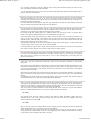
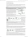
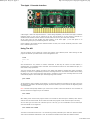
SB-Projects: Projects: Apple 1
1 von 5
http://www.sbprojects.com/projects/apple1/aci.php
The Apple 1 Cassette Interface
A basic Apple 1 lacks one important feature: a mass storage capability. This is where the Apple 1 Cassette
Interface comes in, from now on referred to as ACI. The ACI allows us to save memory contents to a
standard audio cassette and later load the contents back into memory from this audio cassette.
At the same time the ACI doubles the ROM capacity of the basic Apple 1, from 256 bytes to an
overwhelming 512 bytes (overwhelming back in '76 I mean).
In this chapter I will explain how the cassette interface is used, how it works electrically and how it works
from a software point of view.
Using The ACI
The ACI program can be started by running the program from address $C100. After starting the ACI
program an asterisk is printed and the cursor is dropped one line.
C100R
C100: A9*
@
ACI commands are very similar to monitor commands. In fact they all consist of a start address, a
separating dot, an end address and a command. The command can either be an R for Read from tape, or a
W for Write to tape operations.
The next example writes a block of memory from $0300 until $03FF to cassette tape (data on $03FF is
included). It's the user's responsibility to start the recording function on the cassette recorder before hitting
the Return key. This ensures that the tape speed is constant as soon as the recording starts and it will
automatically skip the clear leader tape at the beginning of the cassette.
0300.03FFW
\
To play back the same recording to the Apple 1 you must first locate the recording on the tape. Then type
the following command to the Woz ACI program, but don't hit Return yet! Hit return at the beginning of the
10 second header.
Note: The back slash prompt indicates your return to the monitor. It does not indicate an error situation! In
fact the ACI does not support any error indication.
0300.03FFR
\
After hitting return the Woz ACI program waits a few seconds to allow the tape to stabilize, after which it
waits for the end of the header. At the end of the header the program will be read from tape to memory.
You can also type more than one command per line. This way you can concatenate several read and/or
write commands on one single line.
0000.00FFW 0200.0FFFW
\
The above command will first write a 10 seconds long header, followed by the data from $0000 to $00FF.
This is then immediately followed by a new 10 seconds long header and the data from $0200 to $0FFF
31.07.2012 14:52
SB-Projects: Projects: Apple 1
2 von 5
http://www.sbprojects.com/projects/apple1/aci.php
This is then immediately followed by a new 10 seconds long header and the data from $0200 to $0FFF.
It is extremely important to keep the address ranges during read commands exactly the same as they
were used with the respective write commands.
TIP: You can add a spoken note in front of each recording with information about the following data such as
purpose, start and end addresses.
Spaces are ignored in the input field. The commands are only executed as soon as you press the Return
key. Only the characters 0..9, A..F, 'R', 'W' and '.' are allowed in the ACI input field. Any other character
(including lower case and Ctrl characters) will cause the parsing of the input field to stop, returning you to
the beginning of the ACI program.
Errors are detected when parsing the input line. This means that a command line with multiple commands
may be executed only partially until the input error is detected.
It is the intention to keep the address range of a read command equal to the address range used by the
command which wrote the data to tape. The start address of the memory block may be different however.
This allows you to read a piece of data into another memory location.
Be warned though that reading data into a different location will most likely result in a program which
doesn't work because absolute addresses are not automatically renumbered.
In fact the address range of the playback may differ, with the possible result of a program which does not
work. It is not really a problem if the address range on tape is shorter than the read address range. All
available data is read from tape, only control is not returned to the ACI or Woz Monitor because the ACI
program is still waiting for more data to arrive.
This probably means that you'll have to press RESET to regain control of the Apple 1. In that case the data
read from tape is still in memory and can be used as intended.
In case the address range on tape is longer than the range you've selected to be read you'll end up with the
part of data you have selected. The rest of the data on tape is simply ignored.
Tip: Recordings made with the ACI are fairly unreliable measured by today's standard. For example there
is no error correction/detection performed on the data read from tape. If you're saving very important
data, save it twice or maybe even three times in a row. If one recording fails, you'll always have the
other(s) to fall back on.
There are a few minor differences between the input of ACI commands compared to Woz Monitor
commands.
First of all the entire page $0200 is used for input, not only the first half of it like with the Woz Monitor. This
shouldn't be a problem because you probably don't need more than 30 bytes of input buffer anyway. Only if
you want to do something silly, like entering more than 256 characters you'll notice that the ACI program
simply forgets the first 256.
Next comes the fact that the ACI program does not allow the use of a back space character. If you detect a
typing error before you hit Return you can simply press ESC to trash it all and start your command from
scratch.
Hexadecimal input errors can also be corrected by simply typing more than 4 digits. Only the last 4 digits of
a hexadecimal number are used, all preceding digits will be discarded.
There is a small undocumented feature built into the ACI regarding address input. When the input of the
start address is separated from the input of the end address by the separation dot, the start address is
copied to a new location in memory without clearing the old location. Then the end address is composed
into the memory location which still holds a copy of the start address.
Thus if you enter a 3 digit end address, the left most 4th digit will be a left over from the start address.
Entering a 2 digit address will leave you even with 2 digits from the start address.
300.3FFW
The example above will write a block of memory from $0300 to $03FF. No problem, that's what we've
intended, isn't it. Yes it is, but you don't know how lucky you are! In fact the zero in $03FF is a left over
from the right most zero of $0300.
301.3FFW
Now you ran out of luck! The example above will save a block of memory beginning at $0301 and ending at
$13FF! Simply because the '1' is left over from the start address.
In this example the only penalty will be that the recording is far too long. The relevant data is recorded,
along with a lot of irrelevant data. However I can imagine that while reading the same block into memory
it may destroy parts of valuable other data in memory.
31.07.2012 14:52
SB-Projects: Projects: Apple 1
3 von 5
http://www.sbprojects.com/projects/apple1/aci.php
To avoid problems with this undocumented features I advice you to always use a 4 digit end address, even
if there are leading zeroes involved.
The ACI Circuit Description
First of all it is important to place the jumpers on the original Apple 1 main board correctly. These jumpers
can be found at locations B9 and B10. For the ACI a jumper must be connected between points 'R' and 'C',
this causes the ACI ROM to appear in the 13th block of memory (the $Cxxx block).
The description of the hardware is illustrated by some excerpts from the original schematic diagram which
was included in the ACI's user manual. You can find a scan of the ACI's user manual in the download
section.
Let's start with probably the easiest part of the entire
circuit, the input amplifier. Basically it is a zero crossing
detector. The AC input signal is superimposed on a DC
voltage of half the supply voltage, after which it is fed
to the negative input of the opamp. The positive input
of the opamp is held at half the supply voltage and is
used as a reference. Whenever the voltage on the input
is above the reference voltage, the output of the
opamp is low. Otherwise the output of is high. The 47k
resistor provides for a small hysteresis which raises or
lowers the reference voltage a little to avoid jitter
around the tripping point of the circuit.
It can be rather critical to get the input signal level just
right. You'll learn soon enough which volume setting on
your cassette player gives the best results.
To help you to adjust the input level an LED indicator is provided. According to the user manual this LED
should just start to glow fully, whatever that may be. If that doesn't work you should increase the volume
of the cassette player just a little until you get it right.
Next comes the Chip
Select circuitry. As a
bonus this circuit also
includes the cassette
output.
The two NOR gates on
the left decode the
highest address lines
A9, A10, A11 and the
block select signal which is connected to Block 'C' on the Apple 1 main board. Both outputs are "1" when all
4 inputs are low. These two outputs are fed to the 3-input NAND gate, which also gets the Φ2 signal on its
third pin. Only when all 3 lines are high the output will be low.
This all means that the output of this 3-input NAND is low whenever the address is in the range of $C000 to
$C1FF. This signal is used as Chip Select for the PROM, which means that the PROM can be seen from both
ranges starting at $C000 and at $C100. Only the one starting at $C100 is actually used by the software.
The next NOR gate adds the signal from A8 to the game, which means that the output of the NOR gate is
high when the address is in the range from $C000 to $C0FF. This range is actually used as I/O range by the
ACI software.
The signal from the last NOR gate is fed to the flip-flop, which generates the output signal to the cassette
recorder. Each time an address in the range from $C000 to $C0FF is accessed the flip-flop changes state.
The data read from such action can be ignored because all we need is really the read action itself.
The output from the last NOR gate is also fed to the input circuitry which I will discuss next.
Here we have a real clever piece of circuitry. We still
need a way for the software to read the input. Let me
start to explain what the idea behind it is before I'll
show you how it is done.
The output of the input amplifier (AMP) modifies
address line A0 to the PROM whenever an odd address
is read from the range of $C081 to $C0FF. This way the
software actually reads from an even address or an odd address, depending on the output state of the input
amplifier. We will later see how the software interprets this behaviour.
The left most 3-input NAND gets signals from the Chip Select circuit described above, A7 and the input
amplifier's output. Only when all three of those signals are high, the output of the NAND gets low.
This low is combined with the original A0 signal in the next NAND. Its output will follow the inverse of A0 for
as long as the first NAND's output is high, which fortunately is almost always. This can only change when an
address is read in the range from $C080 to $C0FF, then the output of the second NAND will be high if the
31.07.2012 14:52
SB-Projects: Projects: Apple 1
4 von 5
http://www.sbprojects.com/projects/apple1/aci.php
input amplifier's output is high, regardless of the level of A0.
Now we only have to invert the output of the second NAND to achieve the proper polarity of the A0 signal
for the PROM.
Needless to say that this only happens when reading from I/O space! A0 is never modified when reading
from ROM space ($C100 to $C1FF).
And yes, in case you're wondering, the cassette output will constantly change state whenever the cassette
input is polled. But that will be at such a high frequency that you probably won't notice it.
The ACI Software Description
Again it was a very tight fit to squeeze the Apple 1 Cassette Interface software into the 256 bytes of
available PROM. Again there were some concessions to be made regarding the human interface, but we'll
cover them in due time. The source code wozaci.asm is part of a download package which can be
downloaded from the download section.
wozaci.asm program listing
The program starts by printing an asterisk, ACI's prompt, followed by a carriage return. Then the input
buffer pointer is reset before we enter the command input loop. This loop will only exit when a CR is
received or when the ESC key is pressed. The ESC key will send the program back to the beginning of the
ACI program, the CR key will start the parsing of the command(s).
Inside the input loop every typed character is simply stored in the input buffer and echoed to the screen.
This is where we'll find the first concessions regarding the human interface. No attempts are made to reject
control characters for instance, this is not really a problem though because wrong keys will be detected
during parsing anyway. No attempt is made to limit the input buffer length, the entire page 2 can be filled
with input characters. When the page 2 is full the pointer simply wraps around, effectively forgetting all
previous 256 typed characters. Only a fool behind the keyboard will notice this of course.
As soon as a CR character is typed we start the parsing of commands from the input buffer. Remember that
there can be more than one command on each input line.
First of all two 16-bits values are cleared to 0. Keep this in mind, we'll soon find out that this is part of the
undocumented feature I talked about regarding the input of the end address.
There are a total of 3 special characters to be recognized in the input buffer: An 'R', which triggers the Read
command. A 'W', which triggers the Write command. And a dot, which separates the begin and end
addresses. Here we see some other concessions regarding the user interface. For instance it is perfectly
possible to give a Read or Write command without entering either a start or end address. It is also possible
to use more than one separator dot, effectively entering more than 2 addresses for one command. This is
not really a problem, the ACI program simply uses the last two.
Spaces are simply ignored, no matter where they appear. For instance you can type
0 3 0 0 . 0 3 F F W, and it is still accepted!
The last thing we have to parse are the hexadecimal digits. We've seen exactly the same code in the Woz
Monitor. If an illegal character is found the parsing is aborted and the ACI program is restarted from
scratch.
Now it's time to explain the undocumented feature of the end address input. Have a look at the code
following the label SEP. When a dot is entered, the address in HEX1 is copied to HEX2, however HEX1 is not
cleared after that. New hex-digits will shift in from the right, bumping the old digits out from the left. This
means that if you enter less than 4 digits in the second address there are still some digits in HEX1 which
don't belong there any more.
31.07.2012 14:52
SB-Projects: Projects: Apple 1
5 von 5
http://www.sbprojects.com/projects/apple1/aci.php
don t belong there any more.
Obviously it was all a matter of lack of program memory which caused this undocumented feature.
The Write routine starts by writing a 10 seconds long
header, after that the data bytes are written to tape.
Each time a new byte is collected from memory, which
is then shifted out bit by bit. Then the begin address is
incremented until it is higher than the end address.
Because all timing is done in software loops you'll see
quite a lot of compensation instructions in the different
parts of the process. Their purpose is to compensate for
the extra work which is needed to get new bytes, shift
bits and increment addresses.
The Read routine may appear to be a little more
complicated at first, but we'll manage it all the same.
First we try to detect a full cycle of the input signal to
assure us that the tape really has been started. Then
we introduce a short delay to allow the tape speed to
stabilize. The write header routine is abused to create
this delay. This has one extra benefit, it saves the X
pointer for us which we need later in order to parse the
next command. Finally another full cycle is detected to
synchronize the timing with the tape signal.
Then we start a loop which must detect the start bit,
which is shorter than the other bits in the header. When
the start bit is detected we have to wait for the second
half of the start-bit before we can start reading the
actual data.
Now it's time to read in the data. Obviously all bytes contain 8 bits, which explains the RDBIT loop. Inside
this loop we measure the duration of a full cycle. If the timer value passes the 0 we know that the time was
longer than the average between a "1" and a "0", and vice versa. As soon as a byte is read it is stored in
memory, after which the begin address is incremented until it is larger than the end address.
Here we also see some compensation values for the timing to overcome the differences in workload.
The FULLCYCLE routine simply calls the CMPLEVEL routine, which is effectively executed twice this way. The
timer is decremented, which will finally indicate the interval time for a full cycle. And now we come to the
clever part of Steve's hardware. Remember the way we read the input, by manipulating address line A0 to
the PROM? Well the LDA TAPEIN instruction may effectively load the accumulator with the value on $C080
or $C081. We're not interested in the actual value in neither of these addresses, we only want them to be
different. And fortunately they are different.
The CMP #128 instruction at the end will set the Carry flag according to the measured time. If the timer
crosses the 0 the carry will be set, otherwise the carry will be cleared. Now the carry represents the level
of the new bit.
The WHEADER routine is responsible for writing the header to the tape. First of all the parse pointer X is
saved. Then we see two nested loops.
The inner loop uses the X register, which counts a full cycle each time. Well not each time, the first time the
X register doesn't contain 0 to start with. But that is only a marginal difference, which is hardly noticeable.
The outer loop uses the Accumulator as counter. Since there is no DEA instruction on the NMOS version of
the 6502 we have to use the ADC instruction. We only subtract 1 here, because the carry is always set
inside the loop! The end result is indeed a header with a time of about 10 seconds.
When the program finally falls through the outer loop a relatively short bit is written (LDA #30) which will
function as start bit.
Now we arrive at the WRITEBIT routine. This routine is a concatenation of some timing loops. The first loop
times a single phase of the 2 kHz frequency (in case the data bit is 0), this loop is only followed by a second
loop if a 1 kHz phase is required.
The WDELAY routine is executed twice to create a full cycle of the selected frequency.
Finally the INCADDR routine first compares the begin address with the end address to see if we're done.
The actual decision is postponed though to the calling routine, only the Carry flag is set accordingly.
Then the address is simply incremented. And then the 256 bytes of the PROM are completely filled again.
I have only a few last remarks to make regarding the ACI software. First of all there was no room to
initialize the stack pointer again. This means that you cannot read data into page $01 and expect it to
survive the stack actions of the ACI program because the stack can be all over the place.
The second memory space you stay clear of are the addresses $0024 to $0029, which are used by the ACI
program.
Finally you should be aware of the use of page $02 as input buffer. If you keep the tape commands short,
you should be able to use most of page $02 though.
31.07.2012 14:52