1
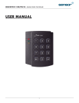
User’s Manual PINPAD Single Door Access Controller Table of Contents 1. Important Safety Instructions .......................................................................... 3 2. General ............................................................................................................... 3 3. Identifying Supplied Parts ................................................................................ 4 4. Features ............................................................................................................. 4 5. Specification ...................................................................................................... 5 6. Installation ......................................................................................................... 5 7. Wire Color of Table............................................................................................ 6 8. Wire Connection................................................................................................ 7 9. Operation ........................................................................................................... 7 10. FCC Registration Information ...................................................................... 10 11. Warranty Policy and Limitation of Liability ................................................. 10 2 1. Important Safety Instructions When using your Single Door Controller, basic safety precautions should always be followed to reduce the risk of fire, electrical shock, and injury to persons. In addition, the following should also be followed: 1. Read and understand all instructions. 2. Follow all warnings and instructions marked on the product. 3. Do not use liquid cleaners or aerosol cleaners. Use a damp cloth for cleaning. If necessary, use mild soap. 4. Do not use this product near water, such as bath-tub, wash bowl, kitchen sink, laundry tub, in a wet basement, or swimming pool. 5. This product should be operated only from the type of power source indicated on the marking label. If you are not sure of the type of power supplied to your installation site, consult your dealer or local power company. 6. Never push objects of any kind into this product or through the cabinet slots as they may touch voltage points or short out parts that could result in fire or electric shock. Never spill liquid of any kind on the product. 7. To reduce the risk of electric shock, do not disassemble this product by yourself, but take it to qualified service whenever service or repair is required. Opening or removing the covers may expose you to dangerous voltages or other risks. Also, incorrect reassembly can cause electric shock when the unit is subsequently used. 8. Unplug this product from the Direct Current (DC) power source and refer to qualified service personnel under these conditions: a. When the power supply cord or plug is damaged or frayed. b. If liquid has been spilled on the product. c. If the product does not operate normally after following the operating instructions in this manual. Adjust only those controls that are covered by the operating instructions in this manual. Improper adjustment of other controls that are not covered by this manual may damage the unit and will often require extensive work by a qualified technician to restore normal operation. d. If the product exhibits a distinct change in performance. 2. General The Star PIN120 is an intelligent single door keypad / controller that combines the convenience of entry control with the security of an alarm system. Also, the Star PIN120 will also give you field proven reliability and cost-effective solution anywhere access controls and security are required. The Star PIN120 can interface and operate with EXIT button. Also, output ports, which include 2 Relays and 1 Bell. Moreover, the status or behaviours of these input and output accessories are configurable to provide the system administrator with complete customized control of the system. 3 3. Identifying Supplied Parts Please unpack and check the contents of the box. PIN120 (1ea) Wall Mount (1ea) O-ring (5ea) 3.5*40 Screw (4ea) 3.5*12 Screw (4ea) Anchor Bolt (4ea) 4. Features - PINPAD Single Door Access Controller - 512 Users - User Defined 4 - 6 digit PIN - Independent 1 Input and 3 Outputs including 2ea of 2 Form-C Relay Outputs - Operation Time of All I/Os Programmable by Keypad - Keypad Lock by Try-out Error Alarm Function - Chime Bell Output - Tamper Switch 4 User’s Manual (1copy) 5. Specification Model PIN120 CPU 8bit Microprocessor Program Memory 8KBtyte ROM Memory Data Memory 2KByte EEPROM User 512 Users Power / Current DC 12V / Max.160mA 1 Port (Exit Button) Input Port 2 Ports (Form-C Relay Output (COM, NO, NC) / Output Port DC12-18V, Rating Max.2A) 1 Port (Chime Bell Output / DC5V, Rating Max. 500mA) Keypad LED Indicator 12 Key Numeric Keypad with Back Lighting 3 Array LED Indicators (Red, Green and Yellow) Beeper Operating Temperature Operating Humidity Color / Material Dimension (W x H x T) Piezo Buzzer -35° to +65°C ( -31° to +149°F ) 10% to 90% relative humidity non-condensing Dark Pearl Gray / Polycarbonate 87mm x 100mm x 31mm (3.4” x 3.94” x 1.22”) Weight 162g (0.36lbs) Certification UL, CE 6. Installation 6-1.Drill two 6-32 or M3 holes 3.3"(8.38cm) apart in vertical and one 1/2" hole at the centre of these two holes. (If you have installed electric gang box then skip this step.) 6-2. Using two 6-32 or M3 screws, install wall mount to the wall. 6-3. Insert 5 O-rings to the wall mount as indicated, then route the cable of the main unit through the centre hole and push the main unit to wall mount to lock the main unit and make sure that the main unit is locked with wall mount. 5 7. Wire Color of Table SIGNAL COLOR Main Power (+12V) Red Power Ground (GND) Black Door Relay Out (COM) Green Door Relay Out (NC) Blue Door Relay Out (NO) Purple Alarm Relay Out (COM) Yellow Alarm Relay Out (NC) Orange Alarm Relay Out (NO) Gray Chime Bell Out Brown Exit Button In White * Please cut out tail connector before installation. 6 8. Wire Connection 9. Operation 9-1. Initial Settings z PIN120 is completely blank when it is delivered to customer. The unit automatically enters to initial setting mode (program mode) when it is powered up. z You may also erase all memory by turn on the power after connecting 2wires. (White and Brown) z Programming sequence is as follows: Connect 12V DC Power supply to RED (+) and BLACK (-) wire then power up You can hear the tune “Sol-Fa-Mi-Re-Do~” and all three LEDs on Press the keypads as follow. (6 digit Master ID) + (ENT) (4~6 digit Access ID) + (ENT) [PIN Access Code] (Up to 512 Access ID) + (ENT) (6 digit Master ID) + (ENT) Tune (Do-Do-Mi-Mi-Sol-Sol) Tune (Mi-Do) Tune (Mi-Do) Tune (Do-Sol-Mi--Do~) 7 red & green LED on red LED on Example) You want to set Master ID “123456” and Access ID “1111”, ”22222” and “345678”. “123456” + (ENT) : Register Master ID “1111” + (ENT) : Register Access ID “22222” + (ENT) : Register Access ID “345678“ + (ENT) : Register Access ID “123456” + (ENT) : Finish Setting Note: Master ID must be 6 digits long and Access ID is 4~6 digit and (ESC) key is to cancel the key input, for example if you want to press “123456” but you pressed “112345” then press ESC key to cancel “112345” then press “123456” + (ENT) to correction. The unit now enters to normal operation mode. With above sequence you already registered “MASTER ID” and “USER ACCESS ID” and the other default settings are automatically set and stored into flash memory. 9-2. Default Setting Values When Access ID Granted Door Relay and green LED activate for 3 seconds Exit Input Entered Door Relay and green LED activates for 3 seconds When Access ID denied When Try-out error occur Bell (ESC) key pressed Alarm Relay and red LED activates for 2 seconds (within Try-out count) Alarm Relay and red LED activates for 2 seconds and Keypad locks for 60 seconds (from 3rd Try-out). Bell sound (Mi-Do~ Mi- Do~), Bell output (open collector) activates for 5 seconds Numbers of Try-out count 3 times Keypad input limit time 20 seconds Keypad lock time 60 seconds Bell output Enable Silent mode Off Tamper Alarm Off Quick Access code Disable 8 9-3. Normal Operation z Yellow LED is blinking every second. z Operating Outputs: 4 ~ 6 digits Access ID + ENT z If Access ID is granted, Door Relay and green LED activates. z If Access ID is denied, Alarm Relay and red LED activates. z Exit Input Entered: Door Relay and green LED activates. z Quick Access (only activates when Quick Access Mode ON): ENT Door Relay and green LED activates z BELL (only activates when BELL Output Time set): ESC Bell output (open collector) activates with bell sound. 9-4. Setting Changes Reset All Outputs (all Relays and Bell output OFF) Master ID+ENT Add New Access ID Master ID+ENT+11+ENT+New Access ID+ENT Delete Access ID Master ID+ENT+13+ENT+Delete Access ID+ENT Door Relay Time Set: Time = 00 ~ 99 seconds Master ID+ENT+21+ENT+TIME+ENT Alarm Relay Time Set: Time = 00 ~ 99 seconds Master ID+ENT+22+ENT+TIME+ENT Bell Output Time Set: Time = 00 ~ 99 seconds Master ID+ENT+23+ENT+TIME+ENT Keypad Input Limit Time Set: Master ID+ENT+25+ENT+TIME+ENT Time = 10 ~ 99 seconds Key Lock Time Set: Time 00 ~ 99 seconds Master ID+ENT+26+ENT+Key Lock Time + ENT Try-Out Count Set: Count = 00 ~ 99 times Master ID+ENT+27+ENT+COUNT+ENT Door Relay Latch (unconditional ON) Master ID+ENT+31+ENT Alarm Relay Latch (unconditional ON) Master ID+ENT+32+ENT Bell Output Latch (unconditional ON) Master ID+ENT+33+ENT Tamper Alarm ON Master ID+ENT+41+ENT Tamper Alarm OFF Master ID+ENT+42+ENT Silent Mode OFF Master ID+ENT+51+ENT Silent Mode ON Master ID+ENT+52+ENT Quick Access Mode ON Master ID+ENT+61+ENT Quick Access Mode OFF Master ID+ENT+62+ENT Master ID Change Master ID+ENT+90+ENT+New Master ID+ENT Erase All Memory And Initialise Settings Master ID+ENT+99+ENT+Master ID+ENT 9 10. FCC Registration Information FCC REQUIREMENTS PART 15 Caution: Any changes or modifications in construction of this device which are not expressly approved by the manufacturer for compliance could void the user's authority to operate the equipment. NOTE: This device complies with Part 15 of the FCC Rules. Operation is subject to the following two conditions; 1. This device may not cause harmful interface, and 2. This device must accept any interference received, including interference that may cause undesired operation. This equipment has been tested and found to comply with the limits for a Class A Digital Device, pursuant to Part 15 of the FCC Rules. These limits are designed to this equipment generates, uses, and can radiate radio frequency energy and, if not installed and used in accordance with the instructions, may cause harmful interference to radio communications. However, there is no guarantee that interference will not occur in a particular installation. If this equipment does cause harmful interference to radio or television reception, which can be determined by turning the radio or television off and on, the user is encouraged to try to correct interference by one or more of the following measures. 1. Reorient or relocate the receiving antenna. 2. Increase the separation between the equipment and receiver. 3. Connect the equipment into an outlet on another circuit. 4. Consult the dealer or an experienced radio/TV technician for help. 11. Warranty Policy and Limitation of Liability IDTECK warrants this product against defects in material and workmanship for 3 years from the date of purchase under normal customer use. This Warranty doesn’t apply: 1) to any product which has been dismantled without authorization of IDTECK or/and has a damaged or detached QC label on its back side; 2) to any losses, defects, or damages caused by improper testing, operation, installation, maintenance, modification, alteration, or adjustment; 3) to any product with a damaged or faded serial number on it; or 4) to any losses, defects, or damages caused by lightning or other electrical discharge, natural disaster, misuse, accident or neglect. This Limited Warranty is in lieu of all other warranties, obligations, or liabilities on the part of IDTECK, and IDTECK DISCLAIMS ANY AND ALL WARRANTY, WHETHER EXPRESS OR IMPLIED, OF MERCHANTABILITY OR FITNESS FOR A PARTICULAR PURPOSE.IDTECK does not, and cannot, know who is present, what property is located, where this product will be used; it would be extremely difficult to determine the actual damages that may result from a failure of the product to perform as anticipated; and the low price of this product is based upon the nature of the product provided and the limited liability that IDTECK assumes. IDTECK IS NOT RESPONSIBLE FOR ANY PERSONAL INJURY, PROPERTY DAMAGE OR LOSS, DIRECT, SPECIAL, INCIDENTAL OR CONSEQUENTIAL DAMAGES, OR OTHER LOSS, AND IDTECK’S MAXIMUM LIABILITY SHALL NOT IN ANY CASE EXCEED THE PURCHASE PRICE OF THE PRODUCT. To obtain repair or replacement under the terms of this warranty, visit IDTECK’s Website (http://www.idteck.com) and place an online RMA request. After an RMA code is issued, return the product along with the authorization RMA code. 10 RMA REQUEST FORM IDTECK accepts only on-line RMA requests on our Website (www.idteck.com). Please provide us with basic information in the below form so that we can understand your problems better. Send us back this form with your products after an RMA code is issued on our Website. This form is not compulsory. RMA Authorization Code : 1. Company Name 2. Model Name 3. Serial No. 4. Original Invoice No. 5. Distributor 6. Purchasing Date 7. RMA Request Date Please check your problems. □ Card Reading □ Communication □ LED & Buzzer □ Power . □ Relay .. □ Keypad . □ LCD □ Registration □ Others : IDTECK RMA Center >> 3F, 10/10-1/10-2, Dodang-Dong, Weonmi-Gu, Bucheon-Si, Gyeonggi-Do 157-030, Korea Telephone: 82.2.2659.0055 (HQ) / 82.32.671.5642 (RMA Center) Fax: 82.2.2659.0086 (HQ) / 82.32.671.5641 (RMA Center ) Website: www.idteck.com e-Training Center: www.idtecktraining.com MAMPIN1HE2X Nov. 2008 Copyright © IDTECK Co., Ltd. The specifications contained in this manual are subject to change without notice at any time. 5F, Ace Techno Tower B/D, 684-1, Deungchon-Dong, Gangseo-Gu, Seoul, 157-030, Korea Tel : +82-2-2659-0055 Fax : +82-2-2659-0086 E-mail : [email protected] MAMPIN1HE2X Nov. 2008 Copyright © IDTECK Co., Ltd.




![ASK[EM] Format Proximity Card Reader](http://vs1.manualzilla.com/store/data/005664035_1-4bfcda642b959ea77ca1da56751cb6af-150x150.png)