1
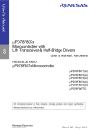
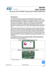
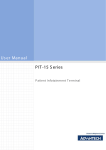
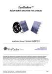
INSTALLATION, OPERATING AND SERVICING INSTRUCTION MANUAL DUCK OVEN Model No.: DR-800 AGA Approval No.; 6785 B&S Commercial Kitchen Appliances Pty Ltd 57 Plateau Road Reservoir VIC 3073 AUSTRALIA Tel: +61 3 9469 4754 Fax: +61 3 94694504 Web: www.b-scka.com.au Please ensure this booklet is kept in a safe and prominent location for future reference. Table of Contents Installation, operating and servicing instruction manual .................................i Duck Oven...................................................................................................i Product Specifications................................................................................. 3 TABLE 1: Nominal Terminal Input Rates & Injector Sizes...............3 TABLE 2: Appliance Dimensions ...................................................3 IMPORTANT WARNING! ............................................................................. 3 Installation Instructions .............................................................................. 4 Regulations ...................................................................................................................... 4 Data Label ........................................................................................................................ 4 Ventilation ........................................................................................................................ 4 Combustible Surfaces ........................................................................................................ 4 Gas Connection................................................................................................................. 4 Pressure test point ............................................................................................................ 4 Before Leaving - Commissioning ........................................................................................ 5 Operating Instructions................................................................................ 5 Figure 1: Duck Oven – Knowing your appliance ............................5 Figure 2: Aerial View – Overheat probe tube.................................6 Lighting Instructions ......................................................................................................... 6 Figure 3: Control Panel................................................................6 Shutdown Procedure ......................................................................................................... 6 Duck Cooking Operating Procedure .................................................................................... 7 Maintenance and Care....................................................................................................... 7 Servicing Instructions ................................................................................. 8 Abnormal Operation .......................................................................................................... 8 TABLE 3: Troubleshooting ...........................................................8 PRODUCT SPECIFICATIONS Appliance Name: B & S Duck Oven Manufactured By: Wing Ming Engineering Co. Ltd Manufactured For: Model Number: B&S Commercial Kitchen Appliances Pty Ltd 57 Plateau Road Reservoir Victoria 3073 Tel; + 61 3 9469 4754 Fax: +61 3 9469 4504 E-mail: [email protected] DR-800 Approval Number: 6785 Gas Type/s: Natural Gas TABLE 1: NOMINAL TERMINAL INPUT RATES & INJECTOR SIZES Gas Type NG Injector Size Burner (mm) 3.30 MJ/h rating per burner Test Point Pressure 60 1.0 kPa TABLE 2: APPLIANCE DIMENSIONS Weight: 140 kg Diameter Across Main Body: 800 mm Height: 1,425 mm IMPORTANT WARNING! THIS APPLIANCE SHALL ONLY BE INSTALLED/SERVICED BY AN AUTHORISED INSTALLER. THIS APPLIANCE MUST BE INSTALLED IN ACCORDANCE WITH THE SPECIFIED INSTRUCTIONS AND SPECIFICATIONS. IMPROPER INSTALLATION OR OPERATION OF THIS APPLIANCE MAY RESULT IN PRODUCT FAILURE WHICH MAY LEAD TO PROPERTY DAMAGE, PERSONAL INJURY OR DEATH. CAUTION MUST BE TAKEN WHEN OPERATING THIS APPLIANCE TO MINIMISE RISK OF FIRE. REGULAR INSPECTIONS BY AN AUTHORISED SERVICE PERSON ARE STRONGLY RECOMMENDED TO ENSURE PROPER FUNCTIONING OF THIS APPLIANCE. AFTER ANY SERVICING OR ADJUSTING OF GAS CONNECTED COMPONENTRY, GAS LEAK TEST MUST BE CARRIED OUT TO ENSURE THERE ARE NO GAS LEAKING HAZARDS. ENSURE ANY TRANSIENT PROTECTION IS REMOVED BEFORE INSTALLING THE APPLIANCE ENSURING ANY POSSIBLE DAMAGE TO THE APPLIANCE OR COMPONENTS/PARTS THAT MAY HAVE BEEN SUSTAINED DURING TRANSPORTATION IS REPORTED TO THE MANUFACTURER. THIS APPLIANCE IS NOT INTENDED TO BE USED IN A MARINE ENVIRONMENT. June 2009 3 6785-01 ENSURE APPLIANCE IS INSTALLED IN A STABLE POSITION. FAILURE TO DO SO WILL VOID THE B&S WARRANTY AND MAY RESULT IN DAMAGE TO EQUIPMENT OR INJURY TO PERSONNEL INSTALLATION INSTRUCTIONS REGULATIONS This appliance must be installed to the requirements of AS 5601 – Gas installations, local gas authorities, local building codes and the manufacturer’s installation instructions. DATA LABEL The data label is located on the front of the appliance. This appliance is suitable for Natural Gas only. Please ensure that the gas supply matches the Data Label ensuring that the gas supply is correct for the appliance being installed and that adequate supply pressure and volume is available – refer to appliance data plate for Mj/hr consumption, injector sizes of main burners/pilots, etc. VENTILATION Ventilation must be in accordance with AS 5601/AG 601- Gas Installations. In general, the appliance should have adequate ventilation for complete combustion of gas, proper fluing and to maintain temperature of immediate surroundings within safe limits. It is recommended that this appliance is installed under an approved canopy or other approved ventilation. COMBUSTIBLE S URFACES This appliance shall be installed on a level surface with and a clear space of 200mm must be kept between the rear of the appliance and the wall. The oven shall be installed so that a clear space of 200mm is maintained between the sides of the oven and any other appliance. No combustible material shall be closer than 750mm from the appliance. GAS CONNECTION Unpack the appliance and remove any protective coating. Place the appliance into its installed position and adjust the legs to the right height and stability. The gas connection is located at the front left hand side approximately 180mm from the floor. The inlet is to the regulator which is a Maxitrol ¾” regulator. Connect to the gas supply using rigid gas piping. For pipe sizing details refer to AS 5601/AG 601- Gas Installations. Light the burner and check test gas pressure at the outlet of the regulator PRESSURE TEST POINT All appliances that are dispatched from our factory are tested and adjusted according to the specifications for the required gas type. The regulator may require adjustment to achieve required gas pressure. Check the burner pressure at the test point on the regulator. The test point pressure should be adjusted to 1.00 kPa – Natural gas with the burners operating at maximum. June 2009 4 6785-01 BEFORE LEAVING - COMMISSIONING Check all connections for gas leaks with soap and water. Do not use a naked flame for detecting leaks. Ignite the pilot and main burners to ensure correct operation of gas valves, burners and ignition. When satisfied with the operation of the appliance, please instruct the user on the correct method of operation. Ensure that this instruction manual is left with owner of the appliance. In the 1. 2. 3. 4. event the appliance fails to operate correctly, check the following; Data plate to ensure correct gas type and pressure (adjust if necessary) Adjust aeration by adjusting air shutter located at the front of the venture of the main burner. Injector sizes – check against data plate and installation manual View pilot size and adjust if required. In case appliance fails to operate correctly after all checks have been carried out, pleased contact; B&S Commercial Kitchen Appliance Pty Ltd 57 Plateau Road Reservoir VIC 3073 Tel.: + 61 3 9469 4754 Fax.: + 61 3 9469 4504 E-mail: [email protected] OPERATING INSTRUCTIONS WARNING! - DO NOT spray aerosols in the vicinity of this appliance while it is in operation. - DO NOT store or use flammable liquids or items in the vicinity of this appliance. - Prior to lighting, smell the area surrounding the appliance for gas (please note that as some gas types are heavier than air, we recommend the operator to also smell the floor around the appliance) - In the event you smell gas: DO NOT light any appliance. DO NOT touch/operate any electrical switch or phone in your building. Call the local gas supplier immediately and follow their instructions FIGURE 1: D UCK OVEN – KNOWING YOUR APPLIANCE Upper Lid Upper Chamber “Viewing” Port Upper Chamber Middle Chamber Middle Chamber “Viewing” Port Gas Controls June 2009 5 6785-01 FIGURE 2: AERIAL VIEW – OVERHEAT PROBE TUBE IMPORTANT! – PLEASE FILL BOTTOM OF UNIT WITH WATER TO COVER PROBE TUBE PRIOR TO OPEATION. Overheat Probe Tube LIGHTING INSTRUCTIONS 1. 2. 3. 4. 5. 6. Turn the main control to “OFF” position. Turn pilot cock to “ON”. Depress blue button and light pilot manually. Hold blue button in for approximately 15 seconds. Observe the pilot is established. If pilot does not establish, wait five minutes and repeat steps 1-5. Turn main gas “ON”. FIGURE 3: CONTROL P ANEL Pilot Control Valve Main Gas (Pictured in Valve “OFF” Over Temperature Reset Flame Failure Safety Devise (Blue Button) SHUTDOWN PROCEDURE 1. Turn main gas valve to “OFF” 2. Turn pilot control valve clockwise to turn “OFF” 3. Observe pilot flame is extinguished. NOTE: This appliance should burn with a blue flame. If the appliance is not burning with a blue flame adjust the aeration shutter located under the appliance base either clockwise or anti clockwise until the flame has a blue tip. June 2009 6 6785-01 If the appliance is burning with a yellow flame and cannot be adjusted to burn correctly please turn the appliance off and contact B&S Commercial Kitchen Appliances Pty Ltd or their authorised service agent. DUCK COOKING OPERATING PROCEDURE 1. Fasten ducks with stainless steel hooks and suspend from the iron ring of the duck oven located on the upper chamber. 2. Then ensure the upper lid is then closed tightly with the upper chamber “viewing” port. 3. Turn the main gas control to the highest flame setting and start cooking the ducks for approximately five minutes. 4. Adjust the flame down as required from the original flame and cook for approximately forty five minutes or until the ducks are fully roasted. 5. Whilst cooking during the slow cook cycle, the operator should check the produce every fifteen minutes via the middle chamber viewing port. NOTE: Cooking time/s may vary on size of ducks. MAINTENANCE AND CARE To ensure longevity and continued performance efficiency of your appliance, a good cleaning and maintenance program is paramount. In general the use of steel wool, abrasive cloths/cleansers/powders should not be used to clean this appliance. D AILY C HECKS & S ERVICE Look for any foreign materials in burner area, leaks, damaged knobs and any other signs that the appliance is not ready and safe for operation. Inspect burner area and ensure pilot is in position near the burner, and that the pilot flame when ignited is blue in color and approximately 10-20mm in length. Ensure pilot flame is in contact with thermocouple. Call the manufacturer if you see any problems. Always ensure that the area surrounding the pilot and thermocouple is clear of any fats, oils or foodstuffs. Drain the fat by opening the drain valve at the right hand side of the main gas valve and allow draining into a tray or vessel. Remove and thoroughly wash all accessories with warm soapy water. Wipe clean all external and interior surfaces that are readily accessible. W EEKLY C HECKS & S ERVICE The cooker base may be cleaned with a damp cloth and mild soap or detergent. The appliance base should never be immersed into water for cleaning. Y EARLY C HECKS & S ERVICE The appliance should be inspected and adjusted periodically by a qualified service person as part of any kitchen maintenance program. B&S recommends that this appliance is inspected at least annually by an authorized service technician as follows; o Inspect the appliance inside-out for excessive build-up of any fats, oils and foodstuffs. Inspect that the burners and other components (i.e. pilots, thermocouples, etc.) are in good condition and functioning properly. o Inspect all gas connections for leaks and ensure all connections are tightened properly. In case of difficulties contact B&S Commercial Kitchen Appliances Pty Ltd or their authorised service agent. June 2009 7 6785-01 SERVICING INSTRUCTIONS WARNING! - Servicing shall be carried out by authorised personnel only. Failure to do so will void the B&S warranty and may result in damage to equipment or injury to personnel. - Before commencing any disassembly/assembly of gas controls, please ensure the gas supply is turned off (isolated). FAILURE TO DO SO WILL VOID THE B&S WARRANTY AND MAY RESULT IN DAMAGE TO EQUIPMENT OR INJURY TO PERSONNEL ABNORMAL OPERATION Any of the following are considered to be abnormal operation and may require servicing; Incomplete ignition of burner/Burner failing to keep alight Check burner is not blocked Yellow tipping of the burner flame Check aeration of burner Gas valves which are difficult to turn TABLE 3: TROUBLESHOOTING FAULT POSSIBLE CAUSE CHECKS Blockage of pilot Check pilot injector is not blocked as described in servicing instructions – pilot and flame safeguard Adjustment of pressure from flame failure control Check gas pressure to pilot as described under servicing instructions – adjustments Pilot light not igniting Positioning of thermocouple Adjust positioning of thermocouple to ensure pilot flame is hitting thermocouple Pilot light not establishing Pilot established, main burner not lighting Burner turning off Check connection of the thermocouple to the control is not loose. Faulty thermocouple Contact manufacturer Faulty flame failure control valve Contact manufacturer Faulty thermocouple Contact manufacturer Faulty flame failure control valve Contact manufacturer Activation of over-temperature control valve Ensure probe is covered in water, undo protective cover for over-temperature cutout devise and press red button to reset. To obtain further service information concerning this appliance, pleased contact; B&S Commercial Kitchen Appliance Pty Ltd 57 Plateau Road Reservoir VIC 3073 Tel.: + 61 3 9469 4754 Fax.: + 61 3 9469 4504 E-mail: [email protected] June 2009 8 6785-01