1
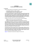
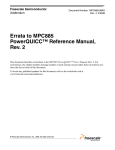
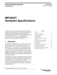
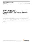
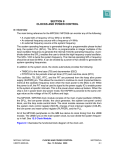
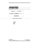
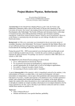
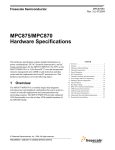
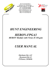
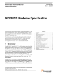
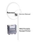
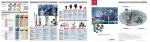
Freescale Semiconductor
Application Note
Document Number: AN2568
Rev. 1, 11/2006
Designing with the MPC852T
by
Ned Reinhold
NCSD Applications
Freescale Semiconductor, Inc.
Austin, TX
The MPC852T is a low-cost member of the
MPC866/MPC859T family of communication processors.
The MPC852T is manufactured using the high performance
HIP6W (0.18 µm) technology, so it can achieve a core
frequency up to 133 MHz.
The MPC852T incorporates the same microprocessor core
and a similar CPM and SIU as the MPC8xx family. The
CPM supports two SCCs (SCC3 and SCC4), SMC1, SPI,
and a 10/100 Fast Ethernet controller module. The SCCs can
support IEEE® 802.3™ Ethernet protocol, but a free
microcode relocation patch is needed if SMC and SPI
support are required. The SCCs also support HDLC/SDLC,
UART, and transparent protocols without the need to
relocate the SMC/SPI parameters. The SIU supports two
user-programmable machines to control memory devices
and peripherals, but the UPWAIT functionality is removed
from one UPM (UPM B). The SIU also supports two 16-bit
timers, timers 3 and 4, that can be cascaded to form one
32-bit timer. However, there is no support for timer gating
because the TGATE1 and TGATE2 pins are removed. The
MPC852T does not support the real-time clock or the 32 kHz
option for clocking. It operates in only two low-power
modes, normal high and normal low.
The MPC852T offers superior value in terms of cost,
performance, and power consumption to members of the
MPC8xx family that are manufactured with pre-HiP
© Freescale Semiconductor, Inc., 2003, 2006. All rights reserved.
Contents
1 Clocks and PLL . . . . . . . . . . . . . . . . . . . . . . . . . . . . . .2
1.1 System and Bus Clocking . . . . . . . . . . . . . . . . . . . 3
1.2 New PLL Implementation . . . . . . . . . . . . . . . . . . .4
1.3 Clock Module . . . . . . . . . . . . . . . . . . . . . . . . . . . . .4
1.4 DPLL Reset Configuration . . . . . . . . . . . . . . . . . . .6
1.5 Clock and Power Control Registers. . . . . . . . . . . . 7
2 Power Requirements . . . . . . . . . . . . . . . . . . . . . . . . . .12
3 Pins . . . . . . . . . . . . . . . . . . . . . . . . . . . . . . . . . . . . . . .13
3.1 5-Volt Tolerant Pins . . . . . . . . . . . . . . . . . . . . . . .13
3.2 Pinout Description . . . . . . . . . . . . . . . . . . . . . . . .14
3.3 Pin Changes . . . . . . . . . . . . . . . . . . . . . . . . . . . . .15
4 Reset . . . . . . . . . . . . . . . . . . . . . . . . . . . . . . . . . . . . . .16
4.1 Debug Port . . . . . . . . . . . . . . . . . . . . . . . . . . . . . .16
4.2 Memory Controller . . . . . . . . . . . . . . . . . . . . . . . .17
5 Revision History . . . . . . . . . . . . . . . . . . . . . . . . . . . . .17
Clocks and PLL
processes and larger geometries. Its phase-locked loop (PLL) clock circuitry is completely redesigned
from that of the MPC860. The new digital phase-locked loop (DPLL) eliminates the need for external loop
filter components. This combination of communications peripherals makes the MPC852T an ideal choice
for a powerful low-end Ethernet router. The MPC850/823 devices offer various levels of integrated
support for USB, video, and LCD devices, but because of the reduced feature set, the MPC852T does not
implement this support in hardware. The increase in performance and the decrease in cost of the MPC852T
often outweigh the additional cost of implementing these features with additional logic.
1
Clocks and PLL
The MPC852T clock system provides many clocking options for all internal and external devices. For its
clock sources, it contains PLL and crystal oscillator support circuitry. Figure 1 illustrates the internal clock
source and distribution that includes the DPLL and interface, clock dividers, drivers, and crystal oscillator.
VDDSYN
PLPRCR[PDF, MFI, MFN, MFD]
PLPRCR[S]
DPLL
MODCK[1:2]
dpdref
1
(PDF + 1)
MFN
2 × MFI +
MFD+1
Interface
Logic
(Divide by
1, 2, 4)
dpgdck
divout1
jdbck
÷2
gclk2
gclk/gclk2
EXTCLK
2:1
MUX
csclk
gclk1c/gclk2c
Low-Power
Dividers/
Clock
Drivers
syncclk
CLKOUT
Driver
tbclk
Time Base
and
Decrementer
Driver
SCCR[PTSEL]
XTAL
EXTAL
Main Clock
Oscillator
OSCM
2:1
MUX
utpclk
brgclk
2:1 MUX
(÷ 4 or ÷ 16)
SCCR
[TBS]
gclk1_50/
gclk2_50
CLKOUT
tmbclk
SCCR[PTDIV]
÷4
÷ 512
2:1
MUX
PIT Clock
and
Driver
pitclk
Note: Only CLKOUT is an actual external output; all other outputs are internal signals.
Figure 1. Internal Clock Source and Distribution
Designing with the MPC852T, Rev. 1
2
Freescale Semiconductor
Clocks and PLL
1.1
System and Bus Clocking
The PLL circuitry can provide a high-frequency system clock from a low-frequency external source. To
enable flexible power control, the MPC852T provides frequency dividers options. It operates at a
maximum system frequency of 133 MHz and a maximum external bus frequency of 66 MHz. Table 1
shows the maximum operating frequency and external bus frequency for both the MPC860/855T and
MPC852T.
Table 1. Maximum Operating Frequency
MPC860/855T
MPC852T
Unit
1:1 Mode
2:1 Mode
1:1 Mode
2:1 Mode
Maximum System Frequency
66
80
66
133
MHz
Maximum External Bus Frequency
66
40
66
66
MHz
To achieve the highest performance, the capacitive loading for the MPC852T external bus must be
minimized as much as possible. The SDRAM should be connected directly to the external bus, while
isolating and buffering slow access devices, such as flash memory and DRAM with data transceivers.
1.2
New PLL Implementation
The MPC852T implements a new DPLL block that eliminates the need for an XFC capacitor. The XFC
pin is a no connect (NC) and is not connected internally. The major changes in the clock and DPLL
implementation are as follows:
• Input clock can only be a 10 MHz crystal at EXTAL/XTAL and/or a 10 MHz or greater oscillator
at EXTCLK.
• Power-on reset DPLL configuration default value has changed.
• The PLL low-power and reset control register (PLPRCR) is used to control the system frequency.
This register now has several different fields (MFN, MFD, MFI, and PDF) for the frequency factor
calculation.
NOTE
The PLPRCR is not backward-compatible with the MPC860/MPC855T.
For details on the clock and DPLL programming module, refer to
Section 1.5.2, “PLL and Reset Control Register (PLPRCR).”
1.3
Clock Module
The clock module consists of two external reference sources and a programmable PLL, as shown in
Figure 2.
Designing with the MPC852T, Rev. 1
Freescale Semiconductor
3
Clocks and PLL
Crystal = 10 MHz
0.1 μF
0.1 μF
GND
EXTAL
XTAL
OSCM
VDD
VSSSYN
VDDSYN
DPLL and
Interface Logic
EXTCLK
VSSSYN1
CKPLPDM
CLKOUT
Low-Power Divider
OSC
Figure 2. Clock Module Components
1.3.1
DPLL and Interface
The programmable MPC852T DPLL generates the overall system operating frequency in integer and
non-multiples of the input clock frequency. The CLKOUT synchronization is not guaranteed for
non-integer multiples of OSCLK. If CLKOUT is an integer multiple of OSCLK/EXTCLK, then the rising
edge of EXTCLK is aligned (locked/synchronized) with the rising edge of CLKOUT. The phase skew
between the rising edges, in this case, lies within a limit of ±3 ns. For a non-integer multiple of EXTCLK,
this synchronization is lost, and the rising edges of EXTCLK and CLKOUT have a continuously varying
phase skew.
Digital implementation of frequency control and loop filtering functions in the design of the DPLL allows
the following new features:
• Eliminating an on-board loop filter capacitor (XFC), minimization of internal capacitor value.
• Selection of frequency and phase/frequency operation modes.
• An improved noise immunity, eliminating additional supply and ground pins.
• A high frequency resolution with a reduced lock time.
• Reduced sensitivity to parameter variations caused be temperature and process.
The main purpose of the DPLL is to generate a stable reference frequency by multiplying the frequency
and eliminating the clock skew. The DPLL allows the processor to operate at a high internal clock
frequency using a low frequency clock input, providing two advantages. First, lower frequency clock input
reduces the overall electromagnetic interference generated by the system. Second, the programmability of
the oscillator enables the system to operate at a variety of frequencies with only a single external clock
source. The OSCLK can be supplied by either a crystal or an external clock oscillator. Crystals are
typically less expensive than clock oscillators; however, a clock oscillator has significant design
advantages over a crystal circuit, in that clock oscillators are easier to work with, resulting in faster design,
debugging, and production.
Designing with the MPC852T, Rev. 1
4
Freescale Semiconductor
Clocks and PLL
The frequency range of OSCLK is 10–160 MHz. Inside the DPLL, OSCLK is divided by the predivision
factor (PDF + 1) to generate the DPDREF clock. The frequency range of DPDREF is 10 to 32 MHz. This
DPDREF clock is used further inside the DPLL for generating the output clock of the DPLL, the DPGDCK
signal. The frequency range of DPGDCK is 160 to 320 MHz. These frequency ranges must be maintained
by both the reset configuration settings and the final operating frequency of the DPLL and interface. The
interface logic works in three modes depending on divider selection input PLPRCR[S]. The formula for
the output frequency of the DPLL and interface logic for each mode is as follows.
jdbck = 2 ×
MFI + (MFN/(MFD +
1))
×
for S = 3, reserved.
NOTE
For synchronization between CLKIN to CLKOUT, the total value by which
the CLKIN is multiplied must be an integer.
This also requires the total MF factor, that is, [MFI + (MFN/(MFD + 1))] to be an integer as a prerequisite.
Table 2 shows the values of the DPLL and interface parameters for typical system frequencies for an input
frequency of 10 MHz.
Table 2. Typical System Frequency Generation for 10 MHz Input
Input
Frequency
(fref)
PDF
MFI
MFN
MFD
PLPRCR
S[10:11]
JDBCK
General System
Frequency
[GCLK2]
10 MHz
0
13
2
9
2
66
33
10 MHz
0
8
0
0
1
80
40
10 MHz
0
9
6
9
1
96
48
10 MHz
0
10
4
9
1
104
52
10 MHz
0
13
2
9
1
132
66
10 MHz
0
15
0
0
1
150
75
10 MHz
0
10
0
0
0
200
100
10 MHz
0
13
3
9
0
266
133
Note: The general system clock [GCLK2] is jdbck divided by 2, and divout1, one of the intermediate signals, is jdbck
divided by 2, as DFNH = 0, CSR = 0.
1.4
DPLL Reset Configuration
While PORESET is asserted, the reset configuration of DPLL is sampled on the MODCK[1–2] pins. The
DPLL immediately begins to use the multiplication factor, pre-division factor values, and the external
clock source for OSCLK determined by the sampled MODCK[1–2] pin and attempts to achieve lock. The
MODCK[1–2] signals should be maintained throughout PORESET assertion. The mode selection field
and various factors are set as shown in Table 3. After PORESET is negated, the MODCK[1–2] values are
internally latched, and the signals applied to MODCK[1–2] can then be changed.
Designing with the MPC852T, Rev. 1
Freescale Semiconductor
5
Clocks and PLL
Table 3. Power-On Reset DPLL Configuration
Default at Power-On Reset
MODCK[1–2]
OSCLK (DPLL and
Interface input)
General System Frequency (GCLK2)
MFI[12–15]
PDF[27–30]
00
8
0000
OSCM frequency
40 MHz (for OSCLK frequency = 10 MHz)
01
15
0000
OSCM frequency
75 MHz (for OSCLK frequency = 10 MHz)
10
8
0011
EXTCLK frequency
1:1 mode
11
15
0000
EXTCLK frequency
75 MHz (for OSCLK frequency = 10 MHz)
Note: Note: S = 1, MFN = 0, MFD = 1 for all of the reset configurations. The general system clock[GCLK2] is jdbck divided by
2, and divout1 is jdbck divided by 2.
NOTE
Under no condition should the voltage on MODCK1 and MODCK2 exceed
the power supply voltage VDDH applied to the part.
At power-on reset, before the PLL achieves lock, no internal or external clocks are generated by the
MPC852T, which may cause higher than normal static current during the short period of stabilization.
1.5
Clock and Power Control Registers
The following sections describe the clock and power control registers.
1.5.1
System Clock and Reset Control Register (SCCR)
The DPLL control register, the system clock and reset control register (SCCR), is shown in Figure 3. This
register is affected by HRESET but not by SRESET.
Designing with the MPC852T, Rev. 1
6
Freescale Semiconductor
Clocks and PLL
0
1
2
3
5
6
7
8
Field
—
COM
—
HRESET
—
#
0
#
#
#
POR
0
0
0
0
*
*
9
TBS PTDIV PTSEL CRQEN
Field
—
DFSYNC
20
DFBRG
21
23
15
0
0
0
†
0
0
0
0
†
0
24
DFNL
14
—
(IMMR&0XFFFF0000) + 280
19
13
EBDF
Addr
18
12
—
R/W
17
11
—
R/W
16
10
26
DFNH
HRESET
0
POR
0
R/W
R/W
Addr
(IMMR&0XFFFF0000) + 282
27
29
DFUTP
30
31
DFAUTP
Notes: HRESET is a hard reset and POR is a power-on reset.
# The field is undefined.
— The field is unaffected.
* PTDIV depends on the combination of MODCK1 and MODCK2. PTSEL depends on MODCK1. See Table 14-4,
in Chapter 14, “Clocks and Power Control,” of the MPC866 PowerQUICC Family User’s Manual, for more
information.
† This field is set according to the default of the hard reset configuration word.
Figure 3. System Clock and Reset Control Register
Table 4. SCCR Field Descriptions
Bits
Name
0
—
1–2
COM
3–5
—
6
TBS
7
PTDIV
Description
Reserved, should be cleared.
Clock output module. This field controls the output buffer strength of the CLKOUT pin. When both
bits are set, the CLKOUT pin is held in the high state. These bits can be dynamically changed
without generating spikes on the CLKOUT pin. If the CLKOUT pin is not connected to external
circuits, clock output should be disabled to minimize noise and power dissipation. The COM field
is cleared by hard reset.
00 Clock output enabled full-strength buffer
01 Clock output enabled half-strength output buffer
10 Reserved
11 Clock output disabled
Reserved, should be cleared.
Timebase source. Determines the clock source that drives the timebase and decrementer.
0 Timebase frequency source is the OSCLK divided by 4 or 16
1 Timebase frequency source is GCLK2 divided by 16
Periodic interrupt timer clock divide. Determines if the clock, the crystal oscillator, or main clock
oscillator to the periodic interrupt timer is divided by 4 or 512. At power-on reset this bit is cleared
if the MODCK1 and MODCK2 signals are low.
0 The clock is divided by 4
1 The clock is divided by 512
Designing with the MPC852T, Rev. 1
Freescale Semiconductor
7
Clocks and PLL
Table 4. SCCR Field Descriptions (continued)
Bits
Name
8
PTSEL
Periodic interrupt timer select. Selects the crystal oscillator or main clock oscillator as the input
source to PITCLK. At power-on reset, it reflects the value of MODCK1.
0 OSCM (crystal oscillator) is selected
1 EXTCLK is selected
9
CRQEN
CPM request enable. Cleared by power-on or hard reset. In low-power mode, specifies if the
general system clock returns to high frequency while the CP is active.
0 The system remains in low frequency even if the communication processor module is active
1 The system switches to high frequency when the communication processor module is active
10
—
Reserved, should be cleared
11–12
—
Reserved, should be cleared.
13–14
EBDF
15–16
—
17–18
Description
External bus division factor. This field defines the frequency division factor between GCLKx and
GCLKx_50. CLKOUT is similar to GCLK2_50. The GCLKx_50 is used by the bus interface and
memory controller to interface with an external system. This field is initialized during hard reset
using the hard reset configuration word described in Section 11.3.1.1, “Hard Reset Configuration
Word,” in the MPC866 PowerQUICC Family User’s Manual.
00 CLKOUT is GCLK2 divided by 1
01 CLKOUT is GCLK2 divided by 2
10 Reserved
11 Reserved
Reserved, should be cleared.
DFSYNC Division factor for the SYNCCLK. This field sets the divout1, where divout1 is equivalent to
JDBCK divided by 2, frequency division factor for the SYNCCLK signal. Changing the value of this
field does not result in a loss-of-lock condition. This field is cleared by a power-on or hard reset.
00 Divide by 1 (normal operation)
01 Divide by 4
10 Divide by 16
11 Divide by 64
19–20
DFBRG
Division factor of the BRGCLK. This field sets the divout1, where divout1 is equivalent to JDBCK
divided by 2, frequency division factor for the BRGCLK signal. Changing the value of this field
does not result in a loss-of-lock condition. This field is cleared by a power-on or hard reset.
00 Divide by 1 (normal operation)
01 Divide by 4
10 Divide by 16
11 Divide by 64
21–23
DFNL
Division factor low frequency. Sets the divout1, where divout1 is equivalent to JDBCK divided by
2, frequency division factor for general system clocks to be used in low-power mode. In low-power
mode, the MPC866 automatically switches to the DFNL frequency. To select the DFNL frequency,
load this field with the divide value and set the CSRC bit. A loss-of-lock condition will not occur
when changing the value of this field. This field is cleared by a power-on or hard reset.
000 Divide by 2
001 Divide by 4
010 Divide by 8
011 Divide by 16
100 Divide by 32
101 Divide by 64
110 Reserved
111 Divide by 256
Designing with the MPC852T, Rev. 1
8
Freescale Semiconductor
Clocks and PLL
Table 4. SCCR Field Descriptions (continued)
Bits
Name
Description
24–26
DFNH
Division factor high frequency. Sets the divout1, where divout1 is equivalent to JDBCK divided by
2, frequency division factor for general system clocks to be used in normal mode. In normal mode,
the MPC866 automatically switches to the DFNH frequency. To select the DFNH frequency, load
this field with the divide value and clear CSRC. A loss-of-lock condition does not occur when this
field is changed. This field is cleared by a power-on or hard reset.
000 Divide by 1
001 Divide by 2
010 Divide by 4
011 Divide by 8
100 Divide by 16
101 Divide by 32
110 Divide by 64
111 Reserved
27–29
DFUTP
30–31
DFAUTP
UTOPIA clock divider; see Chapter 41, “Interface Configuration,” in the MPC866 PowerQUICC
Family User’s Manual, for further information.
1.5.2
PLL and Reset Control Register (PLPRCR)
The PLL and reset control register (PLPRCR), shown in Figure 4, is used to control the system frequency
and low-power mode operation. This register is affected by HRESET and SRESET.
0
4
Field
9
10
11
12
15
MFN
MFD
—
—
—
—
—
0000
00001
0
1
*
27
30
HRESET
POR
5
R/W
R/W
Addr
(IMMR&0xFFFF0000) + 284
16
17
18
19
20
21
Field
—
TEXPS
—
—
—
CSRC
HRESET
—
1
0
0
0
POR
0
1
0
0
0
22
23
MFI
S
24
25
26
–
CSR
—
FIOPD
PDF
DBRMO
0
0
—
—
—
0000
0
0
0
0
0
0
*
0
R/W
R/W
Addr
(IMMR&0xFFFF0000) + 286
31
Notes: HRESET is hard reset and POR is power-on reset.
* POR depends on the combination of MODCK1 and MODCK2.
Figure 4. PLL and Reset Control Register (PLPRCR)
Table 5 describes PLPRCR bits.
Designing with the MPC852T, Rev. 1
Freescale Semiconductor
9
Clocks and PLL
Table 5. PLPRCR Field Descriptions
Bits
Name
Description
0–4
MFN
Numerator of the fractional part of the multiplication factor in the formula for the output frequency of the DPLL
and interface. The range of values for the MFN is 0 to 31. The numerator of the fractional part of the
multiplication factor (MFN) must be less than the denominator of the fractional part of the multiplication factor
(MFD + 1). 1 If the numerator is larger than the denominator, the output clock frequency will differ from the
desired frequency. If the numerator is zero, then the circuit for fractional division is disabled to save power.
Refer to Section 1.10.2.3, “Digital Phase Lock Loop and Interface,” in the MPC866 PowerQUICC Family
User’s Manual.
5–9
MFD
Denominator minus 1 of the fractional part of the multiplication factor in the formula for the output frequency
of the DPLL and interface.The range of values for the MFD is 1 to 31. The denominator of the fractional part
of the multiplication factor (MFD + 1) must be greater than the numerator of the fractional part of the
multiplication factor MFN. 1 If the numerator is larger than the denominator, the output clock frequency will
differ from the desired frequency. If the numerator is zero, then the circuit for fractional division is disabled
to save power.
Refer to Section 1.10.2.3, “Digital Phase Lock Loop and Interface,” in the MPC866 PowerQUICC Family
User’s Manual.
10–11
S
12–15
MFI
16
—
17
Selection bits for the divider after the double clock (fdck)
00 Divide by 1
01 Divide by 2
10 Divide by 4
11 Reserved
Refer to Section 1.10.2.3, “Digital Phase Lock Loop and Interface,” in the MPC866 PowerQUICC Family
User’s Manual.
Integer part of the multiplication factor in the formula for the output frequency of the DPLL and interface. The
range of values for the MFI is 5 to 15. 1 If the MFI is less than 5, the DPLL will use 5.
Refer to Section 1.10.2.3, “Digital Phase Lock Loop and Interface,” in the MPC866 PowerQUICC Family
User’s Manual.
Reserved
TEXPS Timer expired status. Internal status bit set when the periodic timer expires, the timebase clock alarm sets,
the decrementer interrupt occurs, or the system resets.
This bit is cleared by writing a 1; writing a 0 has no effect.
0 TEXP is negated
1 TEXP is asserted
18
—
Reserved, should be cleared.
19
–
Reserved, should be cleared.
20
—
Reserved, should be cleared.
21
CSRC
22–23
–
24
CSR
25
–
Clock source. Specifies whether DFNH or DFNL generates the general system clock. Cleared by hard reset.
0 The general system clock is generated by the DFNH field
1 The general system clock is generated by the DFNL field
Reserved, should be cleared.
Checkstop reset enable. Enables an automatic reset when the processor enters checkstop mode. If the
processor enters debug mode at reset, then reset is not generated automatically. See Section 45.5.2.2,
“Debug Enable Register,” in the MPC855 PowerQUICC Family User’s Manual.
Reserved, should be cleared.
Designing with the MPC852T, Rev. 1
10
Freescale Semiconductor
Power Requirements
Table 5. PLPRCR Field Descriptions (continued)
Bits
Name
27–30
PDF
31
DBRM
O
1
Description
Predivision factor minus 1 in the formula for the output frequency of the DPLL and interface. The range of
values for the PDF is 0 to 15.
Refer to Section 1.10.2.3, “Digital Phase Lock Loop and Interface,” in the MPC866 PowerQUICC Family
User’s Manual.
DPLL BRM order bit
0 First order (should be used when fractional part, MFN/MFD, in undivisible form is greater than 1/10)
1 Second Order (should be used when fractional part, MFN/MFD, in undivisible form is less than 1/10)
This bit is ignored if the MFN is zero.
The total multiplication factor, including both the integer and fractional parts, must be between 5 to 15.
Table 6 describes PLPRCR[CSR] and DER[CHSTPE] bit combinations.
Table 6. PLPRCR[CSR] and DER[CHSTPE] Bit Combinations
2
PLPRCR[CSR]
DER[CHSTPE]
Checkstop Mode
Result
0
0
No
—
0
0
Yes
—
0
1
No
—
0
1
Yes
Enter debug mode
1
0
No
—
1
0
Yes
Automatic reset
1
1
No
—
1
1
Yes
Enter debug mode
Power Requirements
The MPC852T has two voltage levels for the power supply connection. The internal logic and the DPLL
block are fed by 1.8 V (VDDL and VDDSYNC, respectively), while the I/O buffers are supplied by 3.3 V
(VDDH). The keep alive power (KAPWR) pin is not available on the MPC852T and is replaced as an
additional VDDL power pin. Table 7 highlights the power supply voltage levels for each of the power pins.
Table 7. Power Supply Connections
Pin Name
MPC860
MPC852T
VDDH
3.3 V
3.3 V
VDDL
3.3 V
1.8 V
VDDSYN
3.3 V
1.8 V
KAPWR
KAPWR
1.8 V
VSS
Ground
Ground
Designing with the MPC852T, Rev. 1
Freescale Semiconductor
11
Pins
Table 7. Power Supply Connections
Pin Name
MPC860
MPC852T
VSSSYN1
Ground
Ground
VSSSYN2
Ground
Ground
The organization of the power rails is shown in Figure 5. Note that the clock control and DPLL blocks are
now powered by VDDL on the MPC852T, instead of VDDH on the MPC860/855T.
MPC866
I/O Pad
Internal Logic
and
Clock Drivers
Analog
DPLL
VDDL
1.8 V
OSCM, PIT,
TB,
DEC, SCCR,
PLPRCR,
and RSR
TEXP
Clock Control
and DPLL
VDDH
3.3 V
VDDSYN
1.8 V
Figure 5. Organization of the Power Rails
3
Pins
Table 8 shows the pin changes associated with the new DPLL.
Table 8. Pin Changes from 860/855T Migrating to MPC852T
Pin Name
3.1
Pin No.
MPC860/855T
MPC852T
XFC
T2
XFC
No Connect
KAPWR
R1
KAPWR
VDDL
5-Volt Tolerant Pins
The MPC860/855T pins are all 5 V tolerant except the EXTAL and EXTCLK pins. The MPC852T differs
from the MPC860/855T, in regards to which pins are 5 V tolerant. Table 9 lists all the pins on the
MPC860/855T and MPC852T and states whether the pins are 5 V tolerant.
Designing with the MPC852T, Rev. 1
12
Freescale Semiconductor
Pins
Table 9. 5-V Tolerant Pins on MPC860/855T and MPC852T
MPC860/855T
5-V Tolerant
MPC852T
5-V Tolerant
XTAL
No
No
EXTAL
No
No
EXTCLK
No
No
PB[14:31]
Yes
Yes
PA[0:15]
Yes
Yes
PC[4:15]
Yes
Yes
PD[3:15]
Yes
Yes
TDI
Yes
Yes
TDO
Yes
Yes
TCK
Yes
Yes
TRST
Yes
Yes
TMS
Yes
Yes
MII_MDIO
Yes
Yes
MII_TXEN
Yes
Yes
Rest of the 860/866 pins
Yes
No
Pin Name
3.2
Pinout Description
Figure 6 shows the pinout of the MPC852T. The changes are noted as follows:
• All VDDL and VDDSYN pins have been changed to 1.8 V on the MPC852T
• All VDDH pins are 3.3 V on the MPC852T
• Pin T2 has changed from XFC on the MPC860/855T to NC on the MPC852T (see Table 8)
• Pin R1 has changed from KAPWR on the MPC860/855T to VDDL on the MPC852T (see Table 8)
Designing with the MPC852T, Rev. 1
Freescale Semiconductor
13
Pins
A
NC
CS1
WR
CS0
CS7 GPL_A2 WE2
BS_A0
VDDL
A28
A18
A23
A19
A14
A7
A2
A1
NC
A22
A30
A29
A27
A13
A9
A6
A0
NC
B
CE2_A GPL_A3 WE3 MII_CRS BS_A3
C
VDDL GPL_A4 CS3
CS5 GPL_A0 WE1
BS_A2
A26
A25
A21
A17
A12
A8
A3
NC
PC15
BDIP
BI
CS2
CS6
OE
WE0
BS_A1
A31
A24
A20
A15
A10
A4
NC
PB29
VDDL
BR
TS
TEA GPL_A5 CE_1A
CS4
TSIZ1
TSIZ0
A16
A11
A5
NC
PB31
PC13
PC12
PA11
CR
MII_COL
D
E
F
BB
TA
PB30
TDO
TMS
TRST
BURST
BG
PB28
TDI
VDDL
MDIO
TCK
PB25
PA10
PB24
PC5
PC7
PA8
PA9
PD13
PA2
PC6
PA3
NC
PC4
PA1
PB15
G
VFLS_1 RSV
H
ALE_A DSCK VFLS_0 FRZ
GND
J
KR
AS BADDR30 HRESET
OP0
OP1
K
OP2 RSTCONF
VDDH
L
OP3 BADDR29 BADDR28 VDDL
M
EXTAL VDDL SRESET
D26
D14
D9
IRQ1
PD3
PD8
PD15
VDDL
PA0
XTAL EXTCLK WAIT_A VSSSYN IP_A5 CLKOUT D25
D21
D15
D10
D17
IRQ7
PD6
PD9
PD12
PD14
PORST VDDSYN VSSSYN1 DP0
NC
IP_A3
IP_A1
IP_A6
N
P
DP1
D29
D24
D20
D16
D11
D23
D12
IRQ0
PD4
NC
PD11
PD5
R
VDDL
IP_A7
IP_A2
DP3
D31
D28
D6
D19
D5
D2
D27
D13
D0
PD10
NC
NC
IP_A0
IP_A4
DP2
D30
D7
D22
VDDL
D18
D3
D1
D4
D8 MII_TXEN PD7
NC
1
2
3
4
5
6
7
8
9
10
11
12
13
16
T
14
15
Figure 6. MPCPC852T Pinout (Top View)
3.3
Pin Changes
Table 10 lists the pin changes from the 860/855T to the MPC852T
Table 10. Pin Changes from 860/855T to MPC852T
Pins
Comment
IP_B[0–1]/IWP[0–1]/VFLS[0–1]
IP_B[0–1] removed
IWP[0–1] remains
VFLS[0–1] remains
IP_B2/IOIS16_B/AT2
ALL removed
IP_B3/IWP2/VF2
ALL removed
IP_B4/LWP0/VF0
ALL removed
IP_B5/LWP1/VF1
ALL removed
Designing with the MPC852T, Rev. 1
14
Freescale Semiconductor
Reset
Table 10. Pin Changes from 860/855T to MPC852T (continued)
Pins
4
Comment
IP_B6/DSDI/AT0
IP_B6 removed
DSDI removed on this pin, but
appears on the pin, TDI/DSDI
AT0 removed
IP_B7/PTR/AT3
ALL removed
Reset
The hard reset configuration word (HRCW) has changed for the MPC852T to include the additional bit
fields for the new PLL. Additionally, there are changes to the debug port and memory controller bit fields.
4.1
Debug Port
If HRCW is enabled by asserting the RSTCONF pin during HRESET assertion, the HRCW[DBGC] value
must be set to binary 01 in hard reset configuration word (HRCW) and SIUMCR[DBGC] must be
programmed with the same value in the boot code after reset. If HRCW is disabled, by negating the
RSTCONF pin during HRESET assertion, SIUMCR[DBGC] must be programmed with binary 01 in the
boot code after reset. See Table 11 for the hard reset configuration word requirements.
Table 11. Hard Reset Configuration Word Requirements
Bits
Name
9–10
DBGC
Description
Debug pin configuration. Selects the signal function of the following pins:
Pin
DBGC = 00
IWP[0-1]/VFLS[0–1]
11–12
DBPC
Reserved
DBGC = 01
IWP[0–1]
DBGC = 10
Reserved
DBGC = 11
VFLS[0–1]
OP2/MODCK1/STS
STS
STS
DSCK
Reserved
Reserved
OP3/MODCK2/DSDO
OP3
OP3
Debug port pins configuration. Selects the signal function for the following development port pins:
Pin
DBPC = 00
DSCK
OP3/MODCK2/DSDO
DBPC = 01
Defined by DBGC.
Note: If DBPC = 11, DBPC
overrides DBGC.
DBPC = 10
Reserved
DBPC = 11
DSCK
DSDO
TCK/DSCK
DSCK
TCK
TCK
TDI/DSDI
DSDI
TDI
TDI
TDO/DSDO
DSDO
TDO
TDO
Designing with the MPC852T, Rev. 1
Freescale Semiconductor
15
Revision History
4.2
Memory Controller
The MBMR[GPLB4DIS], PAPAR, PADIR, PBPAR, PBDIR, PCPAR, and PCDIR must be configured in
the boot code with the values shown in Table 12.
Table 12. Reset Configuration Requirements
Field
Value
(Binary)
HRCW (hardware reset configuration word)
HRCW[DBGC]
0bx1
SIUMCR (SIU module configuration register)
SIUMCR[DBGC]
0bx1
MBMR[GPLB4DIS}
0
PAPAR (Port A pin assignment register)
PAPAR[4–7]
PAPAR[12–15]
0
PADIR (Port A data direction register)
PADIR[4–7]
PADIR[12–15]
1
PBPAR (Port B pin assignment register)
PBPAR[14]
PBPAR[16–23]
PBPAR[26–27]
0
PBDIR (Port B data direction register)
PBDIR[14]
PBDIR[16–23]
PBDIR[26–27]
1
PCPAR (Port C pin assignment register)
PCPAR[8–11]
PCDIR[14]
0
PCDIR (Port C data direction register)
PCDIR[8–11]
PCDIR[14]
1
Register/Configuration
MBMR (Machine B mode register)
5
Revision History
Table 13 provides a revision history for this application note.
Table 13. Document Revision History
Revision Number
Change(s)
0
Initial release
1
Formatted for Freescale. No substantive changes in content.
Designing with the MPC852T, Rev. 1
16
Freescale Semiconductor
Revision History
THIS PAGE INTENTIONALLY LEFT BLANK
Designing with the MPC852T, Rev. 1
Freescale Semiconductor
17
Revision History
THIS PAGE INTENTIONALLY LEFT BLANK
Designing with the MPC852T, Rev. 1
18
Freescale Semiconductor
Revision History
Designing with the MPC852T, Rev. 1
Freescale Semiconductor
19
How to Reach Us:
Home Page:
www.freescale.com
email:
[email protected]
USA/Europe or Locations Not Listed:
Freescale Semiconductor
Technical Information Center, CH370
1300 N. Alma School Road
Chandler, Arizona 85224
1-800-521-6274
480-768-2130
[email protected]
Information in this document is provided solely to enable system and software
implementers to use Freescale Semiconductor products. There are no express or
implied copyright licenses granted hereunder to design or fabricate any integrated
circuits or integrated circuits based on the information in this document.
Europe, Middle East, and Africa:
Freescale Halbleiter Deutschland GmbH
Technical Information Center
Schatzbogen 7
81829 Muenchen, Germany
+44 1296 380 456 (English)
+46 8 52200080 (English)
+49 89 92103 559 (German)
+33 1 69 35 48 48 (French)
[email protected]
Freescale Semiconductor reserves the right to make changes without further notice to
Japan:
Freescale Semiconductor Japan Ltd.
Headquarters
ARCO Tower 15F
1-8-1, Shimo-Meguro, Meguro-ku
Tokyo 153-0064, Japan
0120 191014
+81 3 5437 9125
[email protected]
parameters, including “Typicals” must be validated for each customer application by
Asia/Pacific:
Freescale Semiconductor Hong Kong Ltd.
Technical Information Center
2 Dai King Street
Tai Po Industrial Estate,
Tai Po, N.T., Hong Kong
+800 2666 8080
[email protected]
unauthorized application, Buyer shall indemnify and hold Freescale Semiconductor
For Literature Requests Only:
Freescale Semiconductor
Literature Distribution Center
P.O. Box 5405
Denver, Colorado 80217
1-800-441-2447
303-675-2140
Fax: 303-675-2150
LDCForFreescaleSemiconductor
@hibbertgroup.com
Freescale™ and the Freescale logo are trademarks of Freescale Semiconductor, Inc.
The Power Architecture and Power.org word marks and the Power and Power.org
logos and related marks are trademarks and service marks licensed by Power.org. All
other product or service names are the property of their respective owners.
Document Number: AN2568
Rev. 1
11/2006
any products herein. Freescale Semiconductor makes no warranty, representation or
guarantee regarding the suitability of its products for any particular purpose, nor does
Freescale Semiconductor assume any liability arising out of the application or use of
any product or circuit, and specifically disclaims any and all liability, including without
limitation consequential or incidental damages. “Typical” parameters which may be
provided in Freescale Semiconductor data sheets and/or specifications can and do
vary in different applications and actual performance may vary over time. All operating
customer’s technical experts. Freescale Semiconductor does not convey any license
under its patent rights nor the rights of others. Freescale Semiconductor products are
not designed, intended, or authorized for use as components in systems intended for
surgical implant into the body, or other applications intended to support or sustain life,
or for any other application in which the failure of the Freescale Semiconductor product
could create a situation where personal injury or death may occur. Should Buyer
purchase or use Freescale Semiconductor products for any such unintended or
and its officers, employees, subsidiaries, affiliates, and distributors harmless against all
claims, costs, damages, and expenses, and reasonable attorney fees arising out of,
directly or indirectly, any claim of personal injury or death associated with such
unintended or unauthorized use, even if such claim alleges that Freescale
Semiconductor was negligent regarding the design or manufacture of the part.
© Freescale Semiconductor, Inc., 2003, 2006.