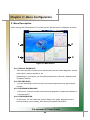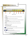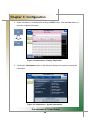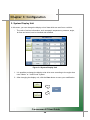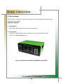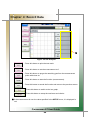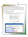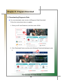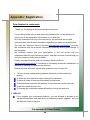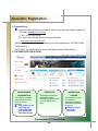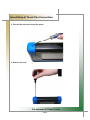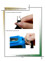
1
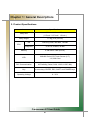
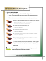
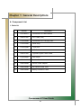
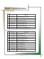
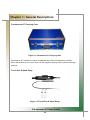
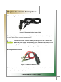
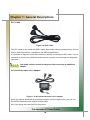
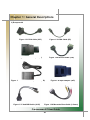
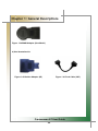
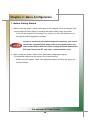
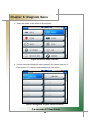
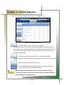
Carmanscan AT User Guide Ver. 100501A Safety Cautions This information is to protect your safety and prevent property damage. Make sure to read it thoroughly before use. 1 Table of Contents Cautions in Use ...................................................................................4 Chapter 1 General Descriptions.........................................................5 1. 2. 3. 4. 5. 6. Product Features............................................................................................. 5 Product Specifications.................................................................................... 6 Rechargeable Battery ..................................................................................... 7 Component List ............................................................................................... 8 Component Figures and Descriptions ........................................................ 11 Power Supply................................................................................................. 23 Chapter 2 Menu Configuration .........................................................24 1. Before Getting Started .................................................................................. 24 2. Menu Description .......................................................................................... 25 3. Icons............................................................................................................... 26 Chapter 3 Configuration ...................................................................27 1. 2. 3. 4. 5. 6. Information..................................................................................................... 27 System Display Unit...................................................................................... 29 Graph.............................................................................................................. 31 Maker..............................................................................................................33 Display ........................................................................................................... 34 Time Set ......................................................................................................... 35 Chapter 4 Record Data......................................................................36 1. 2. 3. 4. Flight Record ................................................................................................. 36 Text Shot ........................................................................................................ 41 Screen Capture.............................................................................................. 43 Gas Analyzer.................................................................................................. 45 Chapter 5 Program Download ..........................................................47 1. Download Program Installation.................................................................... 47 2. Program Download to PC ............................................................................. 49 3. Program Download to Carmanscan AT ....................................................... 53 Carmanscan AT User Guide 2 Table of contents Chapter 6 Diagnosis Menu ...............................................................57 1. How To Connect Self-Diagnostic Connector and Select Diagnosis Program ....................................................................................... 57 2. Automatic Searching Mode .......................................................................... 60 3. General Mode................................................................................................. 64 Chapter 7 Vehicle Diagnosis ............................................................67 1. Diagnostic Trouble Codes ............................................................................ 67 2. Current Data................................................................................................... 70 3. Actuation........................................................................................................ 78 Chapter 8 OBD-II Diagnosis Menu ...................................................80 1. OBD-II Overview ............................................................................................ 80 2. How To Connect Self-Diagnostic Connector and Select Diagnosis Program ....................................................................................... 81 Chapter 9 OBD-II Vehicle Diagnosis ................................................83 1. 2. 3. 4. 5. 6. 7. Readiness Test .............................................................................................. 83 Current Data................................................................................................... 85 Diagnostic Trouble Codes ............................................................................ 87 O2 Test Results.............................................................................................. 89 Monitoring Test Results................................................................................ 91 Vehicle Information ....................................................................................... 93 EPD (Expanded Diagnostic Protocol).......................................................... 95 Appendix Registration ......................................................................98 Hand Strap & Touch Pen Connection.............................................100 Q & A..................................................................................................105 WARRANTY CARD............................................................................107 Carmanscan AT User Guide 3 Cautions in use Safety Instruction Cautions in Use Carmanscan AT mentioned in this User's Guide is designed for those who have basic qualifications for using this system. Users should follow the safety instructions for safe and efficient use of the product. The cautions of use are as follows: Do not drop Carmanscan AT. Always use it in the rubber shroud to product it. Do not place Carmanscan AT on the power distributor. Although Carmanscan AT is manufactured to internally prevent the interference from the electromagnetic waves, the strong interference by excessive electromagnetic waves may damage the product. Excessive surge or electric shock fed by a power cable may damage the power supply system of Carmanscan AT. So, do not use the product while the power supply is unstable. The voltage rating of the AC/DC adapter is 12V DC. Be sure to use an AC/DC adaptor with the rated voltage. Be careful not to let water or oil get into the product. The product can be severely damaged. Be sure to use the USB cable supplied by Our Company only. Otherwise, your PC or product can be damaged. Carmanscan AT User Guide 4 Chapter 1: General Descriptions 1. Product Features Carmanscan AT can check vehicle ECU information and malfunction status through the OBD-I, OBD-II and CAN communication. You can connect Carmanscan AT to the vehicle diagnostic connector with a diagnosis cable to check if any of the engine, automatic transmission, ABS, air bag, power steering and other devices has an error, view current data and use actuator drive features. Carmanscan AT has the following features: ▶ Diagnoses Korean, Japanese and European vehicles. - OBD-I , OBD-II, MOBD(ISO 9141-2, SAE-J1850, KWP-2000, CAN, SAE J1587) ▶ Supports vehicle troubleshooting and current data search. - You can diagnose vehicles with their sensors and switches, and save and reload the current data. ▶ Supports automatic actuator inspection. - This function runs/stops the actuator and switches forcibly in order to check if the corresponding active device is normal. ▶ You can save data and upgrade the diagnosis program by connecting the product to your PC. ▶ You can change the sound effects and display unit of the Carmanscan AT. ▶ Provides the LCD brightness adjustment function. ▶ With the built-in battery, you can perform diagnosis without an additional power supply. (for vehicles without DLC power) Carmanscan AT User Guide 5 Chapter 1: General Descriptions 2. Product Specifications Item Specifications 22.1cm * 14.9cm * 3.8cm Body Size ( 8.7inch * 5.87 inch * 1.5 inch ) Body Weight 1.2 Kg (2.65 pounds) OS Samsung 2440, 400 MHz, 128 MB Diagnosis STR710, 50 MHz, 32 MB CPU Memory LCD 8 GB SDHC Card (built-in) 640x480 Color LCD Touch Screen (5.7”) 115, 200 Color DLC Communication All Flexibility (Serial, CAN, J1850, J1587, MIL) Key 4 arrow keys, ENTER, ESC, SHIFT and POWER keys Operating Voltage 8 - 32 V Carmanscan AT User Guide 6 Chapter 1: General Descriptions 3. Rechargeable Battery * The rechargeable battery pack has the following features - Voltage of the rechargeable battery pack gradually decreases even when the system does not run. - Before using the product for the first time, be sure to fully charge the battery. Always use the rechargeable battery pack provided by Our Company. - Using a 3rd party product may cause explosion. (7.4V 2200 mAh lithium ion battery pack) Do not heat the rechargeable battery pack. - It may cause explosion. Do not short the battery pack terminal. - It may cause explosion. Do not place the battery pack on or near hot material over 60ºC. - It may cause explosion. Keep the battery pack away from touch of children or an animal. - It may cause a fire or injury. To prevent the battery pack from being discharged, always connect the power source before using the system. Screen captures, flight record and other information can be erased due to the discharged battery pack. The rechargeable battery pack is a consumable product and is under warranty for 6 months after purchase. Carmanscan AT User Guide 7 Chapter 1: General Descriptions 4. Component List 1. Basic kit Part No. Description 1 AT00-00001 Carmanscan AT Main Module 2 AA00-07047 DLC Cable (16P) 3 AT00-05000 Carmanscan AT Carrying Case 4 AT00-23045 Hand Strap 5 AT00-23046 Touch Pen 6 AA00-07048 USB Cable 7 AA00-07001 Cigarette Lighter Power Cable 8 AT00-02001 User Guide 9 AT00-01001 Rubber Shroud 10 AA00-06049 AC/DC Power Adapter 11 AA00-06006 AC Electric Power Cord 12 AA00-06002 Battery Extension Cable Carmanscan AT User Guide 8 Chapter 1: General Descriptions 2. Cable Component 1) Korean kit Part No. Description 1 AA00-06007 Hyundai/Mitsubishi Cable (12P) 2 AA00-06009 Kia/Mazda Adaptor (6+1P) 3 AA00-06008 Kia Adaptor (20P, blue) 4 AA00-06010 Daewoo/GM Adaptor (12P) 5 AA00-06011 Ssangyong Adaptor (14P) 6 AA00-06012 Ssangyong Adaptor (20P) 7 AA00-06016 Samsung / Nissan Adaptor (14P) 2) Japanese kit Part No. Description 1 AA00-06014 Toyota Adapter (17R) 2 AA00-06013 Toyota Adapter (17C) 3 AA00-06016 Nissan / Infiniti Adapter (14P) 4 AA00-06007 Mitsubishi Adapter (12P) 5 AA00-06017 Mitsubishi Adapter (12+16P) 6 AA00-06019 Honda Adapter (3P) 7 AA00-06020 Honda Adapter (5P) 8 AA00-06021 Mazda Adapter (17P) 9 AA00-06009 Mazda Adapter (6+1P) 10 AA00-06022 Subaru Adapter (16-9P) Carmanscan AT User Guide 9 Chapter 1: General Descriptions 3) European kit Part No. Description 1 AA00-06026 Audi / VW Cable (2+2P) 2 AA00-06027 BMW Adapter (20P, new) 3 AA00-06044 Mercedes Benz Board (38P) 4 AA00-06028 Mercedes Benz Cable (3 liners) 5 AA00-06029 Opel Adapter (10P) 6 AA00-06030 PSA Cable (2P) 7 AA00-06031 PSA Cable (30P) 8 AA00-06032 Renault Cable (12P) 9 AA00-06033 Fiat Cable (3P) 4) USA/Australian kit Part No. Description 1 AA00-06034 Holden Cable (6P) 2 AA00-06035 Ford Cable (20P) Carmanscan AT User Guide 10 Chapter 1: General Descriptions 5. Component Figures and Descriptions User Guide Figure 1.1 Carmanscan AT User Guide Be sure to read the guide before using the product. Main Module 7 Figure 1.2 Carmanscan AT Main Module * The exterior product without prior notice may be some changes. Carmanscan AT User Guide 11 Chapter 1: General Descriptions * #1: SHIFT key - Holding this key with another key modifies the basic function of the corresponding key. However, pressing this key only does not activate any function. * #2: Power ON/OFF key - Turns power ON/OFF. - Its function is designed to be activated only when it is pressed for 2 to 3 seconds in order to avoid its unintended operation. * #3: LEDs - The power ON/OFF status, USB connection, vehicle diagnosis status and others are indicated by these LEDs. * #4: ESC key - Press this key to move back to the previous screen or cancel an active function. * #5: Arrow keys - Use these keys to move among items left/right/up/down. * #6: ENTER key - Press this key to execute the selected function. * #7: Touch screen LCD panel - Touch a button or others on the LCD screen with a touch pen or finger to activate a function. Carmanscan AT User Guide 12 Chapter 1: General Descriptions Carmanscan AT Carrying Case Figure 1.3 Carmanscan AT Carrying Case Carmanscan AT includes a number of adaptors and cables for diagnosing vehicles. When the product is not in use, store it in the supplied carrying case to prevent damage and loss. Touch Pen & Hand Strap Figure 1.4 Touch Pen & Hand Strap Carmanscan AT User Guide 13 Chapter 1: General Descriptions Rubber Shroud (fit to the main body initially) Figure 1.5 Rubber Shroud The rubber shroud protects Carmanscan AT from external electrical and physical impact. USB Cable Figure 1.6 USB Cable The USB cable connects the USB ports of Carmanscan AT and your PC to download the diagnosis software or save captured files to your PC. Be sure to use the USB cable supplied by Our Company only. Otherwise, your PC or product can be damaged. Carmanscan AT User Guide 14 Chapter 1: General Descriptions Cigarette Lighter Power Cable Figure 1.7 Cigarette Lighter Power Cable The cigarette lighter power cable connects Carmanscan AT with the cigarette lighter jack in your vehicle to feed power to Carmanscan AT. Carmanscan AT has a built-in battery so that you can use it without an additional power supply. If the battery power is weak or the battery is not charged, you can feed power by connecting the main module to the vehicle power source through the cigarette lighter power cable. Battery Extension Cable Figure 1.8 Battery Extension Cable The battery extension cable is used to feed power to Carmanscan AT directly from a vehicle battery through the cigarette lighter power cable. Carmanscan AT User Guide 15 Chapter 1: General Descriptions DLC Cable Figure 1.9 DLC Cable The DLC cable is also called the OBD-II cable. New model vehicles released today all have built-in OBD-II connectors compatible to the OBD-II specification. It is possible to diagnose new model vehicles by directly connecting the DLC cable. It is not necessary to connect any additional power source as power is feed through the diagnostic connector. Old model vehicles should be diagnosed by connecting an additional adapter. AC electrical power cord / adapter Figure 1.10 AC electrical power cord / adapter When you want to download the diagnosis program or search flight record, you can use this AC/DC electrical power adapter to feed power. Also, can charge the battery built in the product. Carmanscan AT User Guide 16 Chapter 1: General Descriptions DLC Adapter The DLC adapter is to diagnose vehicles by connecting it to the DLC main connector. As there are similar shaped adapters, make sure to check the vehicle manufacturer name on the adapter before use. Also, there can be various adapters for one manufacturer. Therefore, be sure to check the shape and pin numbers of the diagnostic connector in the vehicle. Some vehicles do not supply power through the diagnostic connector. Do not connect any power supply if power can be supplied through the diagnostic connector. 1) Korean kit Figure 1.11 Hyundai/Mitsubishi Cable (12P) Figure 1.13 Kia Adapter (20P, blue) Figure 1.12 Kia/Mazda Adapter (6+1P) Figure 1.14 Daewoo, GM Adapter (12P) Figure 1.15 Ssangyong Adapter (14P) Figure 1.16 Ssangyong Adapter (20P) Carmanscan AT User Guide 17 Chapter 1: General Descriptions Figure 1.18 Samsung Adapter (14P) Carmanscan AT User Guide 18 Chapter 1: General Descriptions 2) Japanese kit Figure 1.21 Toyota Adapter (17R) Figure 1.22 Toyota Adapter (17C) Figure 1.23 Honda Adapter (3P) Figure 1.24 Honda Adapter (5P) Figure 1.25 Mitsubishi Cable (12+16P) Figure 1.26 Subaru Adapter (9P) Figure 1.27 Mazda Adapter (17C) Figure 1.28 Mazda Adapter (6+1P) Carmanscan AT User Guide 19 Chapter 1: General Descriptions Figure 1.29 Mitsubishi Adapter (12P) Figure 1.30 Nissan/Infiniti Adapter (14P) Carmanscan AT User Guide 20 Chapter 1: General Descriptions 3) European kit Figure 1.31 PSA Cable (30P) Figure 1.32 PSA Cable (2P) Figure 1.33 Fiat Adapter (3P) Figure 1.34 Renault Cable (12P) Figure 1.35 Mercedes Benz pin board (38P) Figure 1.37 Audi/VW Cable (2+2P) Figure 1.36 Opel Adapter (10P) Figure 1.38 Mercedes Benz Cable (3 liners) Carmanscan AT User Guide 21 Chapter 1: General Descriptions Figure 1.39 BMW Adapter (New Model) 4) Usa/ Australian kit Figure 1.40 Holden Adapter (6P) Figure 1.41 Ford Cable (20P) Carmanscan AT User Guide 22 Chapter 1: General Descriptions 6. Power Supply 1. Cigarette Lighter Power Cable Power is fed through the cigarette lighter power cable. However, when the vehicle ignition switch is in the “OFF” position or upon starting a vehicle, power is not supplied to the cigarette lighter socket. 2. Vehicle Battery Connect the red clip of the battery extension cable to the (+) battery terminal, and black clip to the (-) terminal. Connect the cigarette lighter power cable between the battery extension cable and the product. In this case, power is supplied anytime regardless of the ignition switch status or vehicle starting. (Be careful no to discharge the battery.) Be careful when connecting the cable, as incorrect polarity may damage the main module. 3. DLC Cable Where the vehicle satisfies the OBD-II communication convention and uses a certain manufacturer's diagnostic connector, the DLC main cable can supply power to the product directly without a separate power supply. 4. Rechargeable Battery Pack If the built-in battery is used, you can use the system for 3 to 4 hours without any separate power supply. The available time may change based on use and environment. How to charge: When the product is not in use, connect it to the power source by the AC/DC power adapter that came with the product to charge the built-in battery. 5. AC/DC Power Adapter If the AC/DC adaptor is used for power supply, the battery will be automatically recharged depending on programs and it is also used for power supply to the main module. Carmanscan AT User Guide 23 Chapter 2: Menu Configuration 1. Before Getting Started 1. Before using the system, check if the battery is fully charged. If it is not charged, then connect external power supply or recharge the battery before using the system. - If you use the system by connecting it to a vehicle, you can also feed power to it through the vehicle diagnostic connector. If power is not feed by the vehicle diagnostic connector, you need to connect the cigarette lighter power cable to feed power before you start communication with the vehicle. Voltage mismatch between the ECU and Carmanscan AT may cause a communication error. 2. Before using the system, make sure to download the diagnosis program. The diagnosis program will be stored in the system memory. - Before using the system, check if the diagnosis program matches the option you have purchased. Carmanscan AT User Guide 24 Chapter 2: Menu Configuration 2. Menu Description When turning ON Carmanscan AT, the main screen with the menu is displayed as follow: 1 2 3 4 Figure 2.1 Main Screen # 01. VEHICLE DIAGNOSIS - This menu provides scanner's own functionality such as vehicle diagnosis, service data search, actuator activation, etc. - Depending on your option, you can perform diagnosis on Korean, Japanese and European vehicles. # 02. RECORD DATA - You can check flight record, text shot and screen capture and use gas analyzer function. # 03. PROGRAM DOWNLOAD - In this menu, you can connect to the download program to update the software in Carmanscan AT. # 04. CONFIGURATION - In this menu, you can check the system display unit, graph, background color, favorite setting, screen setting, time setting and system information. Carmanscan AT User Guide 25 Chapter 2: Menu Configuration 3. Icons When turning ON Carmanscan AT, the main screen with the menu is displayed as follow: 1 2 3 4 5 6 7 8 Figure 2.2 Icons 1. HOME - Pressing this button returns to the main screen in the initial booted status. 2. Path Box - This displays the path of the currently running function. 3. Text Shot - Pressing this icon can store all current data values of a system being diagnosed. 4. Screen Capture - The screen being displayed on the LCD can be taken and stored. 5. SHIFT - This button is used to modify the basic function of each function key. 6. Clock - This displays the current time. 7. Battery Charging Status - This shows the charging status of the built-in battery. : The status of an external DC power is supplied and at the same time indicates the status of being charged. : Displays the battery status After charging the battery discharge to prevent use. 8. Back - Pressing this button returns to the previous screen. Carmanscan AT User Guide 26 Chapter 3: Configuration 1. Information In this menu, you can check and enter user and system information. Figure 3.1 Information > User Info. 1. Select Information from the Configuration menu. 2. My Profile is displayed and this information can be edited. - When the cursor blinks on the desired text, click the EDIT button. Carmanscan AT User Guide 27 Chapter 3: Configuration 3. When information is modified after clicking the EDIT button, click the Save button to save the modified information. Figure 3.2 Information > Editing “My Profile” 4. Clicking the Information button on the left pane displays the system and program information. Figure 3.3 Information > System Information Carmanscan AT User Guide 28 Chapter 3: Configuration 2. System Display Unit In this menu, you can change the display unit of data which are sent from a vehicle. - The units of various information, such as speed, temperature, pressure, angle, air flow and sound, can be checked and modified. Figure 3.4 System Display Unit 1. It is possible to change the display units all at once according to the region that uses “Metric” or “Yard-Pound” system. 2. After changing the display unit, click the Save button to save your modification. Carmanscan AT User Guide 29 ` ` `` Chapter 3: Configuration - SPEED : You can change between Km/h and MPH. - TEMPERATURE : You can change between ℃ and ℉. - PRESSURE : You can change among mbar, kPa, inHg and psi. - ANGLE : You can change between ° and %. - AIR FLOW : You can change between gm/s and lb/m. - SOUND : It can be turned ON or OFF. Carmanscan AT User Guide 30 Chapter 3: Configuration 3. Graph In this menu, you can configure graphs that are displayed for data from sensors. - The graph line color, background color and graph line thickness can be set. Figure 3.5 Graph > Init 1 : Pressing this button displays the graph in its initial status as shown in the figure 3.5. : Pressing this button displays the graph in its initial status in the white background. : When making a change to the setting, click the Save button to save the modified setting. Then, the graph is displayed in the modified status. Carmanscan AT User Guide 31 Chapter 3: Configuration : Press this button to change the background color as desired. : Press this button to change the color of the vertical line on the grid. : Press this button to change the color of the horizontal line on the grid. : Press this button to change the color of the cursor which appears on which the screen is touched. : Press this button to change the color of each graph for up to 8 channels. Up to 8 channels can be displayed on the screen at once. : Press this button to select the color of the channel graph. : Press this button to adjust the thickness of the graph line. Figure 3.6 CH. Color screen Carmanscan AT User Guide 32 Chapter 3: Configuration 4. Maker It is possible to select your favorite vehicle maker to be displayed on top in the diagnosis menu. - This function can save time to search for the desired vehicle maker whenever the diagnosis is made. Figure 3.7 Maker : Press this button to check the list of the diagnosis programs that are stored in the internal memory. You can erase the diagnosis data (version, vehicle maker) by a vehicle maker. : Press this button to initialize your favorites. The selected favorite items are deselected. : Press this button to store the selected favorites. This favorites are displayed as icons in order in the diagnosis menu. The favorite list displayed in this menu can also include makers of diagnosis programs that are not downloaded. Carmanscan AT User Guide 33 Chapter 3: Configuration 5. Display In this menu, you can align the touch screen coordinates, setup the language and adjust the LCD brightness. - If the touch screen coordinates are not accurate, they can be corrected through the calibration function. Also, the brightness of the LCD can be adjusted so that the product can be fit both in dark and bright places. Also, the system language can be selected and set by a user. Figure 3.8 Display : Pressing this button displays the touch screen calibration panel. Press the (+) symbols shown on the screen to correct the coordinates automatically. : Press this button to check if the coordinates are calibrated correctly through the calibration function. System Language : The language of the operating system and diagnostic program can be set among the languages that are stored in the internal memory. LCD Screen Brightness : Press the “-” and “+” buttons to adjust the screen brightness. Carmanscan AT User Guide 34 Chapter 3: Configuration 6. Time Set You can change the date and time stored in the internal memory. - The time stored in this menu is used when saving a file or executing other functions. Figure 3.8 Display Date Set: Change the day, month and year as desired by pressing the arrow keys (▲ and ▼). Time Set: Change between AM and PM as well as the hour and minute as desired by pressing the arrow keys (▲ and ▼). OS language setting, depending on the state set a date and time settings can be changed notation. Carmanscan AT User Guide 35 Chapter 4: Record Data In this menu, you can check the flight record, text shots and screen captures and utilizes the gas analyzer function. 1. Flight Record In this menu, you can save the service data for your vehicle for analysis. - You can save the desired service data. - This function is useful when data should be saved to diagnose an intermittent symptom. Figure 4.1 Flight Record : Click this button to display the data only selected by the user. : Click this button to delete the file selected by the user. : Click this button to rename the file that was temporarily set when saving the file (only in English). Carmanscan AT User Guide 36 Chapter 4: Record Data - Text View: Click this button to check the saved data in numbers. 1 2 Figure 4.2 Data_Text View 1. Maker >> Diagnostic program version >> Language version >> System >> Diagnostic connector 2. Total time >> Interval >> Selected time : Press this button to switch to the graph screen from the text screen. █ Total time: The total time of the saved flight record is displayed. █ Interval: This indicates the time from the initial clicked position of the bar on top to the point that the bar is dragged and released. █ Selected time: This indicates the time of the currently clicked position of the bar in the total time. Carmanscan AT User Guide 37 Chapter 4: Record Data - Graph View: Click this button to switch to the graph screen for tendency analysis. Figure 4.3 Data_Text View : Press this button to switch to the text screen from the graph screen. : Press this button to configure the displayed graph. : In the graph screen, up to 8 current data are displayed at once. If more than 8 current data are saved, click the channel ▲ and ▼ keys to scroll the current data. Carmanscan AT User Guide 38 Chapter 4: Record Data - Graph config: Press this button to set the channel, current value and max./min. values of graphs Figure 4.4 Data_Graph config (CH Config) : Clicking this button displays the panel on the right to setup each displayed graph by a channel. : Pressing this button extends the horizontal axis on the grid for more precise graph analysis. : Pressing this button shortens the horizontal axis on the grid to display more data on the screen at once. : 5 current data are displayed on the screen at once by default. The number of data displayed on the screen can be set from 1 to 8. : Press this button to show or hide the current value of the sensor. Carmanscan AT User Guide 39 Chapter 4: Record Data : Press this button to show or hide the maximum and minimum values for each sensor on the right side of the screen. : Press this button to show or hide the sensor names. : Press these buttons, you can increase or decrease the maximum value for each channel to increase or decrease the graph values. Carmanscan AT User Guide 40 Chapter 4: Record Data 2. Text Shot This function is to save all values of the current data for the selected moment from a system being diagnosed. This is used to save data at a certain moment and analyze them. - As all data can be saved at once, you can diagnose your vehicle conveniently. Figure 4.5 Text Shot > Item selection : Press this button to display all saved data for the selected item(s). : Press this button to delete the selected item. : Press this button to rename the selected file from the temporarily set name. Carmanscan AT User Guide 41 Chapter 4: Record Data - Full Screen: As all current data are saved for the selected system, you can utilize the full screen function to check the vehicle condition conveniently. Figure 4.6 Text Shot > Full Screen : Press this button to return to the Text Shot list. Carmanscan AT User Guide 42 Chapter 4: Record Data 3. Screen Capture You can take a screen capture and save it when necessary. - As you can take a screen capture with a simple action, this function is very convenient and useful for your diagnosis. Figure 4.7 Screen Capture : Press this button to show the saved files on a full screen. : Select several files and press this button to display them in a slide show. : Press this button to set the number of repetition and the display time of each file in a slide show and to adjust the color and thickness of the red marker in a full screen. : Press this button to rename the file. : Press this button to delete a file. Carmanscan AT User Guide 43 Chapter 4: Record Data - Full Screen: The red marker function can be used in the full screen. You can make or edit a note onto a saved screen capture. Figure 4.8 Full Screen > Red Marker : Press this button to activate the red marker function. Then, click on the screen and drag it to make a mark. : Press this button to edit the contents written with the red marker function. : Press this button to save the written contents. : If several data are selected in the Image list (Figure 4.7), you can switch between images and use the red marker function. : Press this button to deactivate the function. Carmanscan AT User Guide 44 Chapter 4: Record Data 4. Gas Analyzer Gas analyzer in conjunction with the Carmanscan AT implementation and analyzes the Measurements available. How to connect 1. Preparation NGA 6000 module, RS232C cable and Carmanscan AT 2. Connection - Connect the NGA 6000 module to Carmanscan AT with the RS232C cable. - Click on the Gas Analyzer button. Figure 4.9 NGA 6000 AUTOMOTIVE EMISSION ANALYZER Carmanscan AT User Guide 45 Chapter 4: Record Data ① Figure 4.9 Gas Analyzer : Press this button to print the test result. : Press this button to set the measurement to 0. : Press this button to purge the remaining gas from the measurement probe with clean air. : Press this button to start the function (measurement). : Press this button to cancel the function and return to the previous screen. : Press this button to switch to the bar graph. : Press this button to setup the test items and criteria. ① If the measurement is over the value specified in the SETUP menu, it is displayed in red. Carmanscan AT User Guide 46 Chapter 5: Program Download It is necessary to download the vehicle diagnosis program to your product in order to use it. If there is any update due to a new model, system or development, the program should be updated to the latest one. Also, the latest firmware and PIC data are provided for update to ensure the best performance of your product. For this update, the dedicated program is needed. The following describes how to install the program. 1. Download Program Installation 1. Use the USB supplied by Our Company to connect the PC and Carmanscan AT 2. Select [Program Download] in the main screen Carmanscan AT Carmanscan AT User Guide 47 Chapter 5: Program Download 3. Program installation start. Click Next. Click Close. 4. The following icon appears on your desktop. Carmanscan AT User Guide 48 Chapter 5: Program Download 2. Downloading Diagnosis Data ● You can download a new version of [Diagnosis Data Download]. Follow the instructions below to update. 1. Enter your ID and Password, and then click LOGIN. 2. Click Download Center and then click Software Download displayed under it. Carmanscan AT User Guide 49 Chapter 5: Program Download 3. If you select a manufacturer, its programs will be displayed at the right hand side. Check the program version and if it is for Carmanscan AT, and then click. 4. Once again check the file name (program version and device name) and click. Carmanscan AT User Guide 50 Chapter 5: Program Download 5. The following screen will appear. Follow on-screen instructions to complete installation. Click [Save]. 6. Specify where to save. Click [My Computer]. Double click [local disk (C:)] Double click [Program Files] Carmanscan AT User Guide 51 Chapter 5: Program Download Double click Nextech. Double click Carmanscan AT. Double click Update. Click the Save button. 4. The following windows appears. Click the Close button. 5. The diagnostic data (example: EA1060ENG.DAT) is now saved in the Update folder. The diagnostic data can be downloaded to Carmanscan AT only when they are saved in the specified location. Carmanscan AT User Guide 52 Chapter 5: Program Download 3. Program Download to Carmanscan AT #1 - After the download program is installed to your PC, download the program to Carmanscan AT by connecting it to your PC with the supplied USB cable. 1. Select [PROGRAM DOWNLOAD] on the main screen of Carmanscan AT. 2. Double click the icon on your desktop to run the program. 3. Click Program Download. Carmanscan AT User Guide 53 Chapter 5: Program Download 4. Check the diagnosis program(s) to download in the PC Hard Disk list. Then, click the Download button. 5. When the program is downloaded, the following dialogue box appears. Then, Click the Finish button and remove the USB cable from Carmanscan AT. * If PC download program was installed automatically download. Carmanscan AT User Guide 54 Chapter 5: Program Download 6. When the USB cable is removed, the update operation is automatically start. - OS, STR, PIC update is operating 12V DC power. 7. When the program is downloaded, the following dialogue box appears. Click the Reboot button. Then, the system reboots and the update is completed. Download the complete diagnostic data continuously to the internal memory unit Carmanscan AT will be saved. Carmanscan AT User Guide 55 Chapter 5: Program Download 4. Program Download to Carmanscan AT #2 - PC-Manager application was installed when updating to a more convenient way possible. 1. PC-Manager application was installed, the diagnostic program in the from of the following icons will be changed. 2. Click on the diagnostic data, diagnostic data, the information below appears. [NEXT] keys are pressed the update process. 3. Once the update, the following screen appears, [OK] key is pressed to complete the download. Carmanscan AT User Guide 56 Chapter 6: Diagnosis Menu 1. How To Connect Self-Diagnostic Connector and Select Diagnosis Program (for Korean, Japanese and European vehicles) 1. Locate the diagnostic connector in the vehicle. - Most vehicles released after year 2002 conform to the OBD-II Protocol and have OBD-II diagnostic connectors. - Most OBD-II vehicles have their diagnostic connectors on the section over the brake pedal under the steering wheel. (Figure 6.1) - If an additional adaptor is required, the scanner display shows the type of the necessary adaptor and the location of the diagnostic connector. (Figure 6.2) Figure 6.1 Location of OBD-II Figure 6.2 Adapter and DLC diagnostic connector location guide screen 2. Use the diagnosis cable to connect the vehicle's diagnostic connector and Carmanscan AT. 3. Turn on Carmanscan AT. - If power is not feed through the diagnostic connector and the Carmanscan AT battery is not fully charged, you need to connect an additional power supply (vehicle battery or cigarette lighter power cable, etc). 4. Select the [VEHICLE DIAGNOSIS] menu. Carmanscan AT User Guide 57 Chapter 6: Diagnosis Menu 5. Select the maker of the vehicle to be diagnose. Figure 6.3 Vehicle maker selection 6. If there are several diagnostic data versions in the internal memory of Carmanscan AT, select the desired diagnosis data version. Figure 6.4 Diagnosis program version selection Carmanscan AT User Guide 58 Chapter 6: Diagnosis Menu 7. Select the vehicle model to be diagnose. Figure 6.5 Vehicle model selection 8. Select the system to be diagnose. Figure 6.6 System selection Carmanscan AT User Guide 59 Chapter 6: Diagnosis Menu 2. Automatic Searching Mode In this mode, the system establishes communication with all ECUs in the vehicle and displays only the responded modules for easier diagnosis. 1. Select the vehicle maker to be diagnose. Figure 6.5 Vehicle maker selection 2. Select the diagnosis program version. Figure 6.6 Diagnosis program version selection Carmanscan AT User Guide 60 Chapter 6: Diagnosis Menu 3. Select the vehicle model to be diagnose. Figure 6.7 Vehicle model selection 4. Select AUTO SEARCHING. Figure 6.8 AUTO SEARCHING mode selection Carmanscan AT User Guide 61 Chapter 6: Diagnosis Menu 5. Select the diagnostic connector from the list. Figure 6.9 Diagnostic connector selection 6. The system search starts in the AUTO SEARCHING mode. Figure 6.10 System search If the diagnosed vehicle is a high-end or recent model so is equipped with many systems, this search can take an extended period of time. Carmanscan AT User Guide 62 Chapter 6: Diagnosis Menu * Diagnostic connector types (ex : Toyota models / common for Lexus) 1. 16-pin connector: common OBD-II connector 2. 16-pin connector with CAN: OBD-II connector for vehicles with CAN 3. Semi-circular connector: Toyota 17-pin C-type connector 4. Rectangular connector: Toyota 17-pin R-type connector The screen displays the vehicle diagnostic connector by a vehicle maker. Carmanscan AT User Guide 63 Chapter 6: Diagnosis Menu 3. General Mode In this mode, Carmanscan AT tries typical protocol communication with each system for the corresponding vehicle maker. Except exceptional cases, it is possible to communicate with systems in your vehicle in the general mode without selecting vehicle maker for more convenient diagnosis. 1. Select the vehicle maker to be diagnose. Figure 6.11 Vehicle maker selection 2. Select the diagnosis program version. Figure 6.12 Diagnosis program version selection Carmanscan AT User Guide 64 Chapter 6: Diagnosis Menu 3. Select GENERAL from the menu. Figure 6.13 GENERAL mode selection 4. Select the diagnostic system. Figure 6.14 System selection Carmanscan AT User Guide 65 Chapter 6: Diagnosis Menu 5. Select the diagnostic connector. Figure 6.15 Diagnostic connector selection The automatic searching mode and general mode are useful when searching for systems available for diagnosis at once or when the desired vehicle maker is on the list but the desired vehicle model is not on the list. Communication may not be established with systems in some vehicles in the general mode. In this case, select the correct vehicle model and try again. Carmanscan AT User Guide 66 Chapter 7: Vehicle Diagnosis 1. Diagnostic Trouble Codes - In this menu, it is possible to check for any malfunction of the selected vehicle system through the communication with the ECU in the vehicle. As Carmanscan AT displays DTCs (Diagnostic Trouble Codes), you can easily check where malfunction occurs. Also, the description for DTCs is displayed as well to help you service your vehicle. In order to check for DTCs, you need to connect Carmanscan AT to the vehicle diagnostic connector correctly. Refer to Chapter 6 “Diagnosis Menu” for correct connection. Also, recheck the specifications, such as the vehicle maker, vehicle model, displacement, etc. Figure 7.1 DTC selection NOTE) The menu for DTC selection, shown in the figure 7.1, can differ by vehicle makers and models. 1. When selecting the correct vehicle model and system from the menu and communication with the vehicle is properly established, the menu appears as the figure 7.1. Select DIAGNOSTIC TROUBLE CODES and press the ENTER key. If the message indicating a communication error is displayed instead of the menu like the figure 7.1 or communication cannot be established, check the vehicle condition and the connection status of the diagnostic connector again. Carmanscan AT User Guide 67 Chapter 7: Vehicle Diagnosis Figure 7.2 DTC 1 2. The DTC search screen appears. Now, you can check current and old DTCs and erase them. Old DTCs are not activated unless there is no corresponding fault history. Diagnostic Trouble Codes detected only when the text shot can be saved. 3. Press the Current DTC button to check if there is any current DTC. Figure 7.3 DTC 2 Carmanscan AT User Guide 68 Chapter 7: Vehicle Diagnosis : Press this button to check for DTCs again. The module checks the ECU information again for DTCs. : Press this button to display detailed information for DTCs. : Press this button to check Freeze Frame data for malfunction. : Press this button to check the DTC list for malfunction if the vehicle is equipped with MIL. : Press this button to clear DTC. Figure 7.4 DTC 3 There are current and old DTCs. When trying to clear old DTCs, they are cleared immediately and they are not set again. However, when trying to clear current DTCs, they are cleared for a short period of time but they are activated again. In this case, clear DTCs again after checking and repairing malfunction parts for the corresponding DTCs. Carmanscan AT User Guide 69 Chapter 7: Vehicle Diagnosis 2. Current Data - In the CURRENT DATA menu, the module can communicate with the vehicle ECU to check data and control values of each sensor of the selected system and to check conditions of various switches and actuators. It is important to select the vehicle specifications correctly for accurate sensor data measurement. Make sure to set the vehicle displacement, manufactured year, fuel, etc. correctly. The current data list can differ even with the same vehicle models. Figure 7.5 Current data item selection NOTE) The menu for current data selection, shown in the figure 7.5, can differ by vehicle makers and models. 1. When selecting the correct vehicle model and system from the menu and communication with the vehicle is properly established, the menu appears as the figure 7.5. Select CURRENT DATA and press the ENTER key. If the message indicating a communication error is displayed instead of the menu like the figure 7.5 or communication cannot be established, check the vehicle condition and the connection status of the diagnostic connector again. Carmanscan AT User Guide 70 Chapter 7: Vehicle Diagnosis 2. The current data list is displayed as shown in the figure 7.6. Figure 7.6 CURRENT DATA 1 : Press this button to check current data in graphs. - It is helpful to convert the current vehicle data to graphs for tendency analysis. (Up to 30 items can be selected while up to 8 graphs can be displayed at a time.) - To convert current data to graphs, such data are need to be fixed. Then, only these fixed data change. : Press this button to save sensor data or check the saved files. - Data are stored in the internal memory and they can be stored synchronized with your PC. : Press this button to display DTCs at once. : If the selected system has help information, this button is activated. Then, press this button to display information. When fixing only certain items, values of only these items change. Therefore, the data change measurement is performed faster and more precise diagnosis can be achieved. Carmanscan AT User Guide 71 Chapter 7: Vehicle Diagnosis - Graph View: This function is to check current data in graph forms for tendency analysis. Figure 7.7 CURRENT 2 : Press this button to switch to the text view mode. : Press this button to switch to the graph view mode and display the maximum and minimum values of the measured sensor data. - In the normal mode, the maximum and minimum values of each sensor are programmed into the ECU and these programmed values are displayed. : Press this button to deactivate the automatic mode. Then, the maximum and minimum values are displayed in the normal mode. : In the graph view mode, up to 8 current data can be displayed at a time. If the number of sensor data displayed on the screen at a time is set to less than 8, the remaining current data are displayed in the list on the bottom. (Adjust the number with the up/down buttons.) Carmanscan AT User Guide 72 Chapter 7: Vehicle Diagnosis - File: Press this button to save data or check the saved data. Figure 7.8 Flight Record Data : Press this button to start to record the selected sensor data. - The data can be recorded for up to 1 hour and the recording time can vary depending on the number of the selected current data. (When the recording operation is performed for 1 hour, it stops automatically.) : Press this button to check or search for the stored file(s). Carmanscan AT User Guide 73 Chapter 7: Vehicle Diagnosis - Record Data Viewer: Press this button to search for the stored data or retrieve and display data as necessary. 1. The screen displays the Record Data menu pane where you can check the saved data through the flight record list. 2. For the flight record, text shot, screen capture and gas analyzer functions, refer to Chapter 4. Record Data. Figure 7.9 Record Data Viewer Carmanscan AT User Guide 74 Chapter 7: Vehicle Diagnosis - Graph Config: Press this button to set the channel, current value and max./min. values of graphs. Figure 7.10 Graph Config : Clicking this button displays the panel on the right to setup each displayed graph by a channel. : Pressing this button extends the horizontal axis on the grid for more precise graph analysis. : Pressing this button shortens the horizontal axis on the grid to display more data on the screen at once. : 5 current data are displayed on the screen at once by default. The number of data displayed on the screen can be set from 1 to 8. : Press this button to show or hide the current value of the sensor. Carmanscan AT User Guide 75 Chapter 7: Vehicle Diagnosis : Press this button to show or hide the maximum and minimum values for each sensor on the right side of the screen. : Press this button to show or hide the sensor names. : Press this button to increase/decrease the maximum value range to zoom in and out the displayed graphs. : Press this button to stop the screen while checking current data. Pressing this button again starts the screen. Carmanscan AT User Guide 76 Chapter 7: Vehicle Diagnosis - Show DTC: The upper half of the screen displays the current data while the lower half of the screen displays the DTC list. If there is any DTC, the corresponding sensor data can be checked for comparison. Figure7.11 Current data & DTC : Press this button to exit the dual display mode and return to the Record Data Viewer. Carmanscan AT User Guide 77 Chapter 7: Vehicle Diagnosis 3. Actuation - In this menu, you can start and stop actuators and switches forcibly to diagnose them. - The actuation function is available depending on vehicle makers and models. Figure 7.12 ACTUATION > Selection 1. When selecting the correct vehicle model and system from the menu and communication with the vehicle is properly established, the menu appears as the figure 7.12. Select an item to actuate. If the message indicating a communication error is displayed instead of the menu like the figure 7.12 or communication cannot be established, check the vehicle condition and the connection status of the diagnostic connector again. 2. The screen Figure 7.13 ACTUATION > 1 appears. Carmanscan AT User Guide 78 Chapter 7: Vehicle Diagnosis 3. Pressing the Start button starts the actuation function. - Before starting actuation, make sure to check the operating condition to inspect the system in the proper condition. - The actuation time differs by the actuated items. Figure 7.13 ACTUATION > 1 4. Pressing the Stop button stops the actuation function. - Press this button to stop the actuation function during diagnosis. - Pressing the ESC button on the main module or the arrow button on the right top corner of the screen also stops the actuation function. : Press this button to switch from the text view mode to the graph view mode. The actuation result is judged by noise from the running actuator or switch and vehicle RPM change. Therefore, it is recommended to perform the actuation test in a quiet area and use current data values as a reference. Carmanscan AT User Guide 79 Chapter 8: OBD-II Diagnosis Menu 1. OBD-II Overview ■ Purpose of OBD-II - OBD-II is intended to find what caused the emission to increase, diagnose the part of the cause and light the warning lamp in order to provide faster and more precise repair. ■ OBD-II Regulations - If emission increases due to defected parts, diagnose components and cause, and turn on the Malfunction Indicator Lamp (MIL). - Trouble information shall be read by the standard diagnosis tools (GST). ■ OBD-II Regulations《 Major Check List 》 The warning light shall be on before the emission reaches 1.5 times of the permissible limit due to any of the following troubles or performance degradation. - Catalyst purification rate (this diagnosis is for HC emission only. This is being phased in for 1.75 times of HC limit from TLEV), misfire, EGR System, O2 sensor and fuel system secondary air system - Diagnose all sensors and actuators used for controlling the engine to see if they function properly as well as wirings for an open/short circuit. - Diagnose the entire evaporation system to see if it leaks. - Perform diagnosis when the PCV valve and the crankcase or the PCV valve and the intake manifold are disconnected. - Diagnose the thermostat when the coolant temperature fails to reach the specified temperature where the diagnosis can be made to other items in a given time after starting the engine. Carmanscan AT User Guide 80 Chapter 8: OBD-II Diagnosis Menu 2. How To Connect Self-Diagnostic Connector and Select Diagnosis Program (For Korean, Japanese and European vehicles) 1. Locate the diagnostic connector in the vehicle. - Most OBD-II vehicles have their diagnostic connectors on the section over the brake pedal under the steering wheel. (Figure 8.1 OBD-II Diagnostic connector location) - Since vehicles without the OBD-II diagnostic connector do not conform to the OBD-II communication protocol, you can not use the OBD-II Vehicle Diagnosis function to them. Figure 8.1 OBD-II Diagnostic connector location 2. Use the diagnosis cable to connect the vehicle's diagnostic connector and Carmanscan AT. 3. Turn on Carmanscan AT. - As OBD-II vehicles feed power through the diagnostic connector to the module, they do not need any additional power supply. 4. Select the VEHICLE DIAGNOSIS menu. Then, select OBD-II from the maker list and press the ENTER key. Carmanscan AT User Guide 81 Chapter 8: OBD-II Diagnosis Menu Whenever performing diagnosis, make sure that the ignition switch is in the "ON" position. If the ignition switch is placed in the "OFF" position, power cannot be fed to the ECU and the diagnosis with Carmanscan AT cannot be performed. Carmanscan AT User Guide 82 Chapter 9: OBD-II Vehicle Diagnosis 1. Readiness Test - The readiness test tries making communication with your vehicle to review general items of ECU modules that response. Figure 9.1 Readiness Test Selection 1. If communication with the vehicle is established successfully, the menu shown in Figure 9.1 appears. Select READINESS TEST and press the ENTER key. If no menu like the figure 9.1 is displayed or communication cannot be established, check the vehicle condition and the connection status of the diagnostic connector again. In addition, check if your vehicle supports OBD-II communication. Carmanscan AT User Guide 83 Chapter 9: OBD-II Vehicle Diagnosis Figure 9.2 Readiness Test * Results 1. NOT CMPLTD: The test has not been completed. - This appears when the test was not completed owing to the abnormal ECU or sensor required to display the test result. 2. COMPLETED: The test has been completed. 3. NON APPLIC: The item is not applied to the tested vehicle. Carmanscan AT User Guide 84 Chapter 9: OBD-II Vehicle Diagnosis 2. Current Data - You can check the current data specified by the OBD-II standard in this menu. Figure 9.3 OBD-II Current Data Selection 1. If communication with the vehicle is established successfully, the menu shown in Figure 9.3 appears. Select CURRENT DATA and press the ENTER key. If no menu like the figure 9.3 is displayed or communication cannot be established, check the vehicle condition and the connection status of the diagnostic connector again. In addition, check if your vehicle supports OBD-II communication. Carmanscan AT User Guide 85 Chapter 9: OBD-II Vehicle Diagnosis Figure 9.4 OBD-II Current Data 2. The current data are listed on the screen as shown in Figure 9.4. You can check values of each sensor. Refer to the description from page 69 to page 76 for each button's function. Carmanscan AT User Guide 86 Chapter 9: OBD-II Vehicle Diagnosis 3. Diagnostic Trouble Codes - You can check if there is any current DTC in this menu. Figure 9.5 Diagnostic Trouble Codes Selection 1. If communication with the vehicle is established successfully, the menu shown in Figure 9.5 appears. Select DIAGNOSTIC TROUBLE CODES and press the ENTER key. If no menu like the figure 9.5 is displayed or communication cannot be established, check the vehicle condition and the connection status of the diagnostic connector again. In addition, check if your vehicle supports OBD-II communication. Carmanscan AT User Guide 87 Chapter 9: OBD-II Vehicle Diagnosis Figure 9.6 DTC 2. DTCs are listed on the screen as shown in Figure 9.6. You can check values of each sensor. Refer to the description from page 66 to page 68 for each button's function. Carmanscan AT User Guide 88 Chapter 9: OBD-II Vehicle Diagnosis 4. O2 Test Results - This menu displays monitoring results of the oxygen sensor related items which are required by the OBD-II standard. Figure 9.7 O2 Test Results Selection 1. If communication with the vehicle is established successfully, the menu shown in Figure 9.7 appears. Select O2 TEST RESULTS and press the ENTER key. If no menu like the figure 9.7 is displayed or communication cannot be established, check the vehicle condition and the connection status of the diagnostic connector again. In addition, check if your vehicle supports OBD-II communication. Carmanscan AT User Guide 89 Chapter 9: OBD-II Vehicle Diagnosis Figure 9.8 O2 Test Results 1 Figure 9.9 O2 Test Results 2 2. The oxygen sensor test result is displayed as shown in Figure 9.8/ Figure 9.9. You can check values of the oxygen sensors in this menu. Carmanscan AT User Guide 90 Chapter 9: OBD-II Vehicle Diagnosis 5. Monitoring Test Results - This menu displays the monitoring test results while the vehicle is being normally operated. - To test systems and units of different manufacturers, it is required to specify test IDs and component IDs. If there is no test item supported by the vehicle manufacturer, an error message will be displayed. Figure 9.10 Monitoring Test Results Selection 1. If communication with the vehicle is established successfully, the menu shown in Figure 9.10 appears. Select MONITORING TEST RESULTS and press the ENTER key. If no menu like the figure 9.10 is displayed or communication cannot be established, check the vehicle condition and the connection status of the diagnostic connector again. In addition, check if your vehicle supports OBD-II communication. Carmanscan AT User Guide 91 Chapter 9: OBD-II Vehicle Diagnosis Figure 9.11 Monitoring Test Results 1 Figure 9.12 Monitoring Test Results 2 2. The screen displays the test results for items that were available for the monitoring test as shown in Figure 9.11 / Figure 9.12. Carmanscan AT User Guide 92 Chapter 9: OBD-II Vehicle Diagnosis 6. Vehicle Information - This menu displays information of the ECU installed in your vehicle. - You can check only the ECU that provides its module information. Figure 9.13 Vehicle Information Selection 1. If communication with the vehicle is established successfully, the menu shown in Figure 9.13 appears. Select VEHICLE INFORMATION and press the ENTER key. If no menu like the figure 9.13 is displayed or communication cannot be established, check the vehicle condition and the connection status of the diagnostic connector again. In addition, check if your vehicle supports OBD-II communication. Carmanscan AT User Guide 93 Chapter 9: OBD-II Vehicle Diagnosis Figure 9.14 Vehicle Information 2. You can check information of the ECU equipped in your vehicle as shown in Figure 9.14. Carmanscan AT User Guide 94 Chapter 9: OBD-II Vehicle Diagnosis 7. EDP (Expanded Diagnostic Protocol) - The EDP is intended to provide the following features to enable communication by a random protocol defined by vehicle manufacturers: (SAE J1978 Standard based OBD-II Scan Tool) Carmanscan AT's description of the messages transmitted to vehicles and how to transmit these messages. Carmanscan AT's description of the messages the scan tool will receive and process. Carmanscan AT's description of how to process data containing in the message received. - Generally, the EDP definitions have 4 types as follows: 1) Control type definition <ID>, <Type>, <DSV> 2) Transmit type definition <ID>, <Type>, <Tx msg>, <Rx filter>, <Rx data processing info>, <DSV> 3) Receive-only type definition <ID>, <Type>, <Rx filter>, <Rx data processing info> , <DSV> 4) Miscellaneous type definition <ID>, <Type and additional info>, <DSV> For more details, see SAE J1978 Standard. Carmanscan AT User Guide 95 Chapter 9: OBD-II Vehicle Diagnosis Figure 9.15 EXPANDED DIAGNOSTIC PROTOCOL selection 1. If communication with the vehicle is established successfully, the menu shown in Figure 9.15 appears. Select EXPANDED DIAG. PROTOCOL and press the ENTER key. If no menu like the figure 9.15 is displayed or communication cannot be established, check the vehicle condition and the connection status of the diagnostic connector again. In addition, check if your vehicle supports OBD-II communication. Carmanscan AT User Guide 96 Chapter 9: OBD-II Vehicle Diagnosis Figure 9.16 EXPANDED DIAG. PROTOCOL Use Expanded Diagnosis Protocol only when you have professional knowledge about SAE J1978 Standard or when the vehicle maker's standard is verified. Carmanscan AT User Guide 97 Appendix: Registration Dear Nextech’s customers, Thank you for joining us and purchasing our products. For providing better service and improving convenience, we are pleased to inform you of the registration information of our web site. All of the customers can log in the web site for the technical service and communication with Nextech members regarding car repair and maintenance. The web site “Nextech Service Solution(www.nex-tek.com/carman)” provides the customers with the technical information effectively and a great change in the workplace. We definitely confirm that your participation in this site would help you understand Nextech and Carman products. And also we hope it would help you and your company fruitful and profitable. Finally, we expect that the web site “Nextech Service Solution (www.nex-tek.com/carman)” contributes to increasing customers satisfaction on Nextech by offering rich and prompt services. Please join now and you'll get benefits as below from our web site. To have mutual understanding between Nextech and the customers directly To share the technical information among the customers To have all kinds of business information and services To ask Nextech engineers the problem of your scanner via this web site To get the convenient function To manage the customers needs efficiently by using this web site 1. SIGN UP If you register your purchased products, you are allowed to access to our valuable information and data such as software program upgrade. You can get different levels of service. Carmanscan AT User Guide 98 Appendix: Registration 2. Contact Point If you have any problems and opinion while using this site, please contact us. ① E-mail: [email protected] ② Tel : +82-2-3140-1498 ③ Log on the web site Nextech Service Solution (www.nex-tek.com/carman)”. - O&A menu (You can check the status of your own questions in “MY INFO Q&A Information”) - HOT LINE (You will be able to receive the best solution within 48 hrs.) 3. THE WEB SITE STRUCTURE MAINTENANCE PRODUCTS DOWNLOAD INFORMATION This section Provides Information about Nextech’s products and you can place order here. CENTER This section contains technical information such as Circuit Diagram. ※ This menu can be used only for customers who have purchased Carmanscan VG. Carmanscan AT User Guide 99 This section is used to download diagnosis programs and other application programs. ※ Please contact our local distributor. Hand Strap & Touch Pan Connection 1. Checks the components. - Hand Strap : 1EA - Touch Pan : 1EA - Bolt : 2EA - Nut : 2EA - Hold spring : 2EA * Components of Hand strap * Carmanscan AT User Guide 100 Hand Strap & Touch Pan Connection 2. Take off the bolt cover using the driver. 3. Remove the screw using the driver. Carmanscan AT User Guide 101 Hand Strap & Touch Pan Connection 4. Install the nut. 5. Hold the Hand Strap with the bolt. Carmanscan AT User Guide 102 Hand Strap & Touch Pan Connection 6. Connect the spring to the Hand Strap. 7. And install it to Carmanscan AT. Carmanscan AT User Guide 103 Hand Strap & Touch Pan Connection 8. The picture of Carmanscan AT installed the Hand Strap. 9. The picture of Carmanscan AT installed the Touch pan. Carmanscan AT User Guide 104 Q&A Q) Communication cannot be established. A) 1. Check the connection of the diagnostic cable. - Communication cannot be established if the diagnostic cable is not properly connected. 2. Check if power is properly supplied to the main module. - Vehicle diagnosis can be affected by unstable power source. * If this symptom continues to occur, the hardware of the main module or a component of the vehicle may malfunction. * If this symptom m continues to occur, contact your Dealer for service. 3. Through the power supply from the vehicle diagnostic cables if you do not connect the cable supplying power to the Cigarette Lighter Power Cable. - AT batteries and vehicle batteries in electric potential difference does not communicate Q) I cannot turn on the module. A) 1. Check if the battery in the module is charged. - The built-in battery may not be charged. 2. The battery may not be able to function due to the ambient temperature. - Avoid excessively hot or cold areas. Q) The touch screen does not function properly. A) 1. The touch screen coordinates may not be correctly aligned. - It is possible to test the touch screen coordinates by selecting the CONFIGURATION from the main menu and then selecting DISPLAY and Test Touch Coordinate menus in order. If the coordinates are not correct, correct them using the Calibrate Touch Screen function. * If this symptom continues to occur, contact your Dealer for service. Carmanscan AT User Guide 105 Certificate of Information and Communication Equipment [Certification Label for Information and Communication Equipment] Manufacturer: Nextech Co., Ltd. Equipment: Vehicle diagnosis device Model: Carmanscan AT Manufacturer ID: NEX-Carmanscan AT(A) Manufacturer/Manufactured country: Nextech Co., Ltd./Korea Certificate Date: Dec. 22 2009 COPYRIGHT ⓒ 2010 by NEXTECH All right reserved. No part of this publication may be reproduced, stored in a retrieval system, or in any form, or by any means, electronic, mechanical, photocopying, recording or otherwise, without the prior written permission of the author. Carmanscan AT User Guide 106 WARRANTY CARD Warranty Policy 1. The manufacturer warrants this product to be defect free in material and workmanship for a period of one (1) year from the date of purchase. Defective products may be returned by the original purchaser within the warranty period, postage pre-paid together with proof of purchase date to Nextech Co. LTD. Defective products will be repaired at manufacturer’s discretion, replaced at no charge. 2. The warranty does not apply to any units that have been tampered with, or to damages incurred through improper use and care, defects caused by abuse or through the usage for purposes other than the intended use, used in a manner inconsistent with the instructions regarding use, and faulty packing or mishandling by any common carrier. 3. Repairs not covered by this warranty will be performed at the current cost for parts and labor. In no event will Nextech Co. Ltd’s liability exceed the price paid for the product from direct, indirect, special, incidental or, consequential damages resulting from the use of this product, its accompanying software, or its documentation without obligation to notify any individual or entity. Warranties hereunder extend only to customers and are not transferable. Warranty Period & Software update 1. Warranty period for Nextech products and these’s accessories including software card is one (1) year from the date of sale to the original consumer. 2. Free Software update for Nextech products is one (1) year from date of purchase. After one (1) year from purchase date, software updates will be optional and will require separate payment per request. Repair Service 1. If you suspect that you have a problem with this product, please read the operation manual (guide) carefully to ensure that you are operating this product properly. 2. If you conclude that a real problem exists, check your product according to the procedures on the “Trouble Shooting Card” and mark your trial records in the blank. 3. Please return the main body or the troubled parts along with the “Trouble Shooting Card” to the repair service center listed below. Be sure to return them in freight prepaid as we don’t accept freight collect. Nextech Service Center North America Customer Service Center Nextech Co. Ltd. Nextech America Inc. rd E&C Venture Dream Tower(the 3 ) 13F 7581 Irrine Blrd suite 100 Guro-dong, 197-33 Guro-Gu, Seoul, Korea Tustin Ca, 92780 USA Tel : (822)3140-1489 Fax : (822)3140-1449 Tel: (714)832-0100 Fax: (714)832-0123 Email : [email protected] Email: [email protected] [email protected] Website: www.nex-tech.com/carman 107 WARRANTY CARD Warranty Registration Upon receiving the product, please fill out the following registration form and return either by fax or separate mail to Nextech Service Center or North America Customer Service Center (only USA customer) according to your area. IMPORTANT: Any delay or missing of your warranty registration may cause disadvantage or inconvenience to your warranty repair service. CUSTOMER NAME _______________________________________________________________ COMPANY NAME _______________________________________________________________ ADDRESS _____________________________________________________________________ COUNTRY/STATE ________________________________________ ZIP __________________ TEL NO. _____________________________ FAX NO. _________________________________ EMAIL ADDRESS _______________________________________________________________ SERIAL NO ___________________________ LOT NO _______________________________ SOFTWARE VERSION ___________________________________________________________ DEALERSHIP ____________________________________________________________________ DATE OF PURCHASE MONTH _____________ ___________________________________ DAY ____________ YEAR _____________ __________________________________ SIGNATURE DATE 108