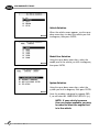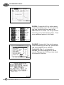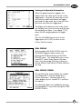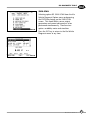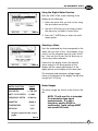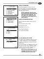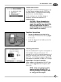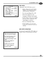
1
Table of Contents
DT-1
Kia
Diagnostic
Tools
Student
Learning Guide
and Workbook
Part Number: UN010 PS 058
S E R V I C E
T R A I N I N G
SAFETY
Appropriate service methods and proper repair procedures are essential for the safe, reliable operation of all
motor vehicles as well as the personal safety of the individual doing the repair. There are numerous variations in
procedures, techniques, tools, and parts for servicing
vehicles, as well as in the skill of the individual doing the
work. This module cannot possibly anticipate all such
variations and provide advice or caution to each.
Accordingly, anyone who departs from the instruction
provided in this module must first establish that he compromises neither his personal safety nor the vehicle
integrity by his choice of methods, tools, or parts. The
following list contains general warnings that should
always be followed while working on a vehicle.
•
Always wear safety glasses for eye protection.
•
Use safety stands whenever a procedure requires
underbody work.
•
Be sure ignition switch is always off unless otherwise
specified by a procedure.
•
Set the parking brake when working on the vehicle.
•
Operate the engine only in a well ventilated area.
•
Keep clear of moving parts when engine is running
•
To prevent serious burns, avoid contact with hot
metal parts such as the radiator, exhaust manifold,
tail pipe, catalytic converter and muffler.
•
Do not smoke while working on a vehicle.
Kia Diagnostic Tools DT-1
Table of Contents
Kia Diagnostic Tools--------------------------------------------------------------------------------------------3
Learning Objectives--------------------------------------------------------------------------------------------3
Module Directions ----------------------------------------------------------------------------------------------3
In-Dealership Directions---------------------------------------------------------------------------------------3
Overview---------------------------------------------------------------------------------------------------------4
Hi-Scan Pro Scan Tool and Diagnostic Set ------------------------------------------------------------------4
Hi-Scan Pro Preparation---------------------------------------------------------------------------------------5
Hi-Scan Pro Cable Connections----------------------------------------------------------------------------5
Power Requirements ----------------------------------------------------------------------------------------5
DLC Connections ---------------------------------------------------------------------------------------------6
Getting Help--------------------------------------------------------------------------------------------------6
Getting Started -------------------------------------------------------------------------------------------------6
Scan Tool Functions--------------------------------------------------------------------------------------------7
Communication Modes-----------------------------------------------------------------------------------------7
Diagnostic Trouble Codes -------------------------------------------------------------------------------------9
Freeze Frame Data------------------------------------------------------------------------------------------- 12
Freeze Frame Data Screen ------------------------------------------------------------------------------- 12
Current Data -------------------------------------------------------------------------------------------------- 12
Current Data Screen -------------------------------------------------------------------------------------- 12
Monitoring Test Results ------------------------------------------------------------------------------------- 15
Monitoring Test Results Screen-------------------------------------------------------------------------- 15
Readiness Test --------------------------------------------------------------------------------------------- 16
Readiness Test Display------------------------------------------------------------------------------------ 16
Heated Oxygen Sensor Test ------------------------------------------------------------------------------ 17
HO2S Monitoring Test Menu Screen--------------------------------------------------------------------- 17
OBD-II Monitoring Test------------------------------------------------------------------------------------ 18
EVAP. Leakage Test ------------------------------------------------------------------------------------------ 19
Flight Record-------------------------------------------------------------------------------------------------- 20
Flight Record Screen -------------------------------------------------------------------------------------- 20
All Data Record -------------------------------------------------------------------------------------------- 20
User Select Data Record---------------------------------------------------------------------------------- 21
Recording Process ----------------------------------------------------------------------------------------- 22
Flight Record Review ------------------------------------------------------------------------------------- 22
Dual Display --------------------------------------------------------------------------------------------------- 23
Dual Display Screen --------------------------------------------------------------------------------------- 23
Simu-Scan ----------------------------------------------------------------------------------------------------- 25
F1: Meter --------------------------------------------------------------------------------------------------- 26
Connecting the Diagnostic Test Lead and Adapter ------------------------------------------------ 26
Using the Digital Meter Function --------------------------------------------------------------------- 27
Selecting a Meter --------------------------------------------------------------------------------------- 27
Meter Ranges -------------------------------------------------------------------------------------------- 27
F2: Simulator Function ----------------------------------------------------------------------------------- 28
Vehicle Scopemeter------------------------------------------------------------------------------------------ 29
Vehicle Scopemeter Options----------------------------------------------------------------------------- 29
Kia Vehicle Auto Scope -------------------------------------------------------------------------------- 29
Engine-------------------------------------------------------------------------------------------------- 30
Sensor Test Conditions --------------------------------------------------------------------------- 30
Reference Waveforms ---------------------------------------------------------------------------- 31
Wave Screens -------------------------------------------------------------------------------------- 31
Manual Scope -------------------------------------------------------------------------------------------- 32
Manual Scope Options ------------------------------------------------------------------------------- 32
Manual Scope Menu ---------------------------------------------------------------------------------- 33
Kia Diagnostic Tools DT-1
Table of Contents
Trigger Selections------------------------------------------------------------------------------------ 33
Hold Mode Options ----------------------------------------------------------------------------------- 34
Flight Record Review -------------------------------------------------------------------------------- 35
Meter ----------------------------------------------------------------------------------------------------- 35
Multimeter Options ---------------------------------------------------------------------------------- 36
Selecting a Meter ------------------------------------------------------------------------------------ 36
Meter Ranges ----------------------------------------------------------------------------------------- 37
Actuator Driving----------------------------------------------------------------------------------------- 37
Sensor Simulator ---------------------------------------------------------------------------------------- 39
CARB OBD-II Diagnosis --------------------------------------------------------------------------------------- 40
CARB OBD-II Diagnosis Format--------------------------------------------------------------------------- 40
Flight Record Review ---------------------------------------------------------------------------------------- 41
Flight Record Review Screen ---------------------------------------------------------------------------- 41
Graph Format ---------------------------------------------------------------------------------------------- 41
System Setup-------------------------------------------------------------------------------------------------- 42
System Configuration ------------------------------------------------------------------------------------- 42
Data Setup -------------------------------------------------------------------------------------------------- 43
Data Setup Operations------------------------------------------------------------------------------------ 43
Printer Setup ----------------------------------------------------------------------------------------------- 44
Printer Operations----------------------------------------------------------------------------------------- 44
Data Down Load ---------------------------------------------------------------------------------------------- 45
PC-Scan Program --------------------------------------------------------------------------------------------- 46
Kia Diagnostic Breakout Box-------------------------------------------------------------------------------- 47
Installing the Breakout Box ------------------------------------------------------------------------------ 47
Installing the Overlay ------------------------------------------------------------------------------------- 49
Activating Output Devices ------------------------------------------------------------------------------- 49
Kia T-Connector Set--------------------------------------------------------------------------------------- 50
KIA DIAGNOSTIC TOOLS
KIA DIAGNOSTIC TOOLS
After completing this module, you will be able
to use the Hi-scan Pro Scan Tool and Diagnostic
Set and the Diagnostic Breakout Box to
diagnose faults and test Kia electrical and
engine management system circuit faults.
Knowing how to properly use the Hi-scan Pro
Scan Tool and Diagnostic Set and the
Diagnostic Breakout Box will enable you to
diagnose and repair electrical and engine
management system problems faster and more
effectively.
LEARNING OBJECTIVES
•
Identify how to properly connect the
Hi-scan Pro to a vehicle.
•
Identify how to use the Hi-scan Pro as
a scan tool, a digital multimeter, and a
two channel oscilloscope to view
various types of OBD-II service data.
•
Identify how to properly connect the
Diagnostic Breakout Box to a vehicle.
•
Identify how to use the Diagnostic
Breakout Box and a multimeter (or Hiscan Pro) to make electrical
measurements and to activate output
devices for testing.
DT1-1
MODULE DIRECTIONS
Carefully read this material. Study each
illustration as you read the material. Be sure to
answer the questions at the end of the module.
IN-DEALERSHIP DIRECTIONS
If you are completing this module as part of an
in-dealership course, you are required to answer
the SELF-STUDY questions on the answer sheet
that was provided. To submit your answer
sheet for grading and course credit, follow the
instructions on the cover sheet that came with
the package. Content is based on information
available as of 3/01/01.
THINGS YOU WILL NEED
Kia Hi-scan Pro Video
m o d u l e
D T- 1
3
KIA DIAGNOSTIC TOOLS
OVERVIEW
• The Hi-scan Pro Scan Tool
and Diagnostic Set
• The Diagnostic Breakout Box
DT1-2
Today’s technicians are faced with many new
challenges. With stricter OBD-II regulations,
increased fuel economy standards, and stricter
emissions requirements, it’s more important
than ever to properly diagnose and repair
electrical and engine management system faults
the first time.
•
VIDEO
To help you save time and increase
accuracy, Kia has made available two
diagnostic tools: The Hi-scan Pro Scan Tool
and Diagnostic Set and the Diagnostic
Breakout Box.
KIA HI-SCAN PRO VIDEO
Before reading this module, take a few minutes
to view the Hi-scan Pro Video. This
presentation highlights the capabilities of the
tester and its accessories.
After viewing the video, continue reading
through the module to gain additional
information about the Hi-scan Pro and also
about the Kia Breakout Box.
HI-SCAN PRO SCAN TOOL AND
DIAGNOSTIC SET
• Functions as:
- Scan tool
The Hi-scan Pro set consists of a hand-held
tester and accessories, which allow the use of
one diagnostic tool for many automotive
applications.
- DMM
- Two Channel Digital
Oscilloscope
- Vehicle Sensor Signal
Simulator
- Actuator driver
• Used stand alone or as a
control center in an
automotive diagnosis system
DT1-3
4
m o d u l e
D T- 1
The Hi-scan Pro is capable of functioning as a
scan tool, a DMM, and a two channel digital
oscilloscope. It can also perform vehicle sensor
signal stimulation and has an actuator driving
function. It can be used stand alone or as a
control center in an automotive diagnosis
system.
KIA DIAGNOSTIC TOOLS
HI-SCAN PRO PREPARATION
In order to use the Hi-scan Pro’s full capabilities
on a Kia vehicle, you must install the latest
Software card. These cards are usually kept in
the tester or in a plastic case inside the
Hi-scan Pro’s carrying case.
Software Card
DT1-4
Insert the Software card into the upper slot on
the right side of the tester. The card is keyed,
so you can’t install it incorrectly. If you are
using the optional “Memory Expansion” card,
slide into the lower slot, below the Software
card.
Hi-scan Pro Cable Connections
DLC Cable
To configure the Hi-scan Pro as a scan tool, you
will have to install the DLC cable and the
proper adapter cable (if required) as shown in
the illustration.
DLC Cable Adapter
OBD-II Compliant Hi-scan Pro
DT1-5
1. Vehicles DLC
2. Hi-scan Pro's optional
internal rechargeable
batteries
•
If you wish to view OBD-II data, connect
DLC cable, P/N 09900-21100, to the
tester.
•
If you wish to view Air Bag, ABS, or OBD-II
information using the underhood DLC, you
must also install adapter cable,
P/N 09900-29020 to the DLC cable.
Power Requirements
3. Locally sourced 12-volt, 2
amp AC/DC adapter that
plugs into a wall outlet or
the AC/DC adapter that is
used with the Data Pro
scan tool
4. DC adapter that plugs into
the vehicle’s cigar lighter
or utility outlet
5. Power extension cable that
connects to the vehicle’s
battery
DT1-6
To use the Hi-scan Pro as a digital meter, an
oscilloscope, or a simulator, it will need a source
of electrical power. The Hi-scan Pro can receive
power from the five different power sources
shown in the illustration.
CAUTION:
When installing batteries in the Hi-scan
Pro, use 7 each of the 1.2v, 1100mAh 1600mAh, AA size, rechargeable type
only! Other batteries may damage the
Hi-scan Pro and will result in a shorter
battery life.
m o d u l e
D T- 1
5
KIA DIAGNOSTIC TOOLS
DLC Connections
• Ignition OFF
• OBD-II Data
- Connect to the DLC under
dash
- Connect to under hood
DLC on most models
• SRS and ABS (1998 and later
models)
- Connect to under hood
DLC
DT1-7
1. Press HELP key
2. Scroll through available
information
To protect the Hi-scan Pro, make sure
that the ignition switch is OFF when
connecting to or disconnecting the
Hi-scan Pro from the DLC.
•
If you wish to view OBD-II data, connect
the DLC cable to the connector under the
instrument panel.
•
If you wish to view air bag information,
connect the adapter cable to the DLC
under the hood. You will also use this DLC
to check ABS information on 1998 and later
models. On most models .(except on the
Optima), the underhood DLC connector
can also be used for OBD-II.
Getting Help
3. Read Operation Guide
DT1-8
Help is available while using any of the Hi-scan
Pro functions by pressing the HELP key. The
help screens provide user information relating
to the current screen. While the Hi-scan Pro
Operation Guide contains all information about
Hi-scan Pro Operation and should always be
used, the Help screens are meant to limit your
time referencing the guide.
GETTING STARTED
1. Turn the ignition on, but do not start the
vehicle.
DT1-9
2. Press the ON/OFF button; you’ll see the
Hi-scan Pro opening screen.
3. Allow the Hi-scan Pro to warm-up and
perform the self-test of its circuits.
4. When the Hi-scan Pro Hardware Version
screen appears, press the ENTER key. The
“INITIAL SCREEN” should appear in the
display.
DT1-10
6
m o d u l e
D T- 1
KIA DIAGNOSTIC TOOLS
• Use the light symbol key to
turn the back light ON or
OFF.
• Adjust the display with the
thumbwheel on the left side
of the tester.
• To turn OFF, hold down the
ON/OFF key until the tester
shuts off.
DT1-11
NOTE: If you do not press the ENTER
key within 30 seconds, the Hi-scan
Pro will shut itself off and you will
have to press the ON/OFF key to
continue.
5. Use the light symbol key to turn the display
back light ON or OFF as required.
6. If you need to adjust the brightness of the
display, there is an adjustment thumbwheel
on the left side of the tester, next to the
telephone jack.
7. If for some reason, you want to turn the
tester OFF, hold the ON/OFF key down until
the tester turns OFF. This delay is there just
in case you accidentally bump the switch.
SCAN TOOL FUNCTIONS
DT1-12
To use the scan tool functions from the “INITIAL
SCREEN”, use the up or down arrow keys to
highlight 01. KIA VEHICLE DIAGNOSIS, then
press the ENTER key.
COMMUNICATION MODES
The Hi-scan Pro scan tool function is capable of
operating in two communications modes:
DT1-13
•
KIA VEHICLE DIAGNOSIS OBD-II - information
specific to Kia vehicles
•
CARB OBD II DIAGNOSIS generic information
required by the SAE
1. KIA VEHICLE DIAGNOSIS, to view all of
the Kia specific OBD-II information available
through the latest program card.
2. CARB OBD-II DIAGNOSIS to display only
the generic OBD-II information required by
the Society of Automotive Engineers (SAE).
This option is sometimes called “Generic
Scan Tool Mode”.
DT1-14
m o d u l e
D T- 1
7
KIA DIAGNOSTIC TOOLS
Vehicle Selection
DT1-15
When the vehicle screen appears, use the up or
down arrow keys to select the vehicle you wish
to diagnose, then press ENTER.
Model Year Selection
DT1-16
Using the up or down arrow keys, select the
model year of the vehicle you wish to diagnose,
then press ENTER.
System Selection
Using the up or down arrow keys, select the
system you wish to diagnose, then press ENTER.
DT1-17
Since this module is designed to support OBDII, we will select 02. 2000 DOHC (BOSCH Sys).
NOTE: If your vehicle has more
than one engine available, you may
be asked to select the engine that
is in the vehicle.
8
m o d u l e
D T- 1
KIA DIAGNOSTIC TOOLS
READINESS TEST STATUS SCREEN
The Readiness Test Status screen will show you
the status of all supported system readiness
tests. The message will be either “all supported
readiness tests are complete or “not all
supported on board system readiness tests have
been completed” Press ENTER to continue; the
KIA VEHICLE DIAGNOSIS MAIN MENU screen
will appear.
DT1-18
DIAGNOSTIC TROUBLE CODES
DT1-19
Selecting option 01. DIAGNOSTIC TROUBLE
CODES from the Kia Vehicle Diagnosis Option
menu and pressing the ENTER key brings up
the DIAGNOSTIC TROUBLE CODES screen.
This screen displays a list of the DTC’s and their
descriptions in the order of occurence. Pending
codes will have a “P” following their
description. The display also shows the total
number of current (confirmed) DTC’s that are
stored and the total number of pending DTC’s.
If there are any current DTC’s, a message will
appear telling you to check the wiring harness
and connectors. Press ENTER to continue.
The following options are available by pressing
the appropriate “F” key while viewing the DTC
menu. Press the escape (ESC) key to return to
the DIAGNOSTIC TROUBLE CODES menu at
any time.
DT1-20
F1: HELP - Pressing the F1 key displays any
tips, wiring diagrams, circuit locations,
connectors, and reference wave patters that
apply to the selected DTC.
F2: ERAS - Pressing the F2 key erases all DTC’s
and Freeze Frame Data. In order to use this
option, you will need the key ON and the
engine OFF.
DT1-21
When you press the F2 key, you will be asked to
confirm your selection by pressing the YES key
to erase all DTC’s and Freeze Frame Data or NO
to return to the DIAGNOSTIC TROUBLE CODES
option menu.
m o d u l e
D T- 1
9
KIA DIAGNOSTIC TOOLS
F3: FRZE - Pressing the F3 key displays the
FREEZE FRAME DATA for the primary DTC (first
one stored and /or one trip DTC). You can also
view Freeze Frame Data by selecting that option
from the Kia Vehicle Diagnosis Main Menu
screen, but this shortcut saves you a few key
strokes.
DT1-22
F4: FLOW - Provides a step-by-step flowchart
with checks and tests followed by “yes” and
“no” questions.
DT1-23
F6: PART - Pressing the F6 key displays the
most effective ways to diagnose the component
or system that most likely caused the
highlighted DTC. Reference waveforms F6
wave may also be available If no information is
currently available, you will be referred to the
service manual.
DT1-24
10
m o d u l e
D T- 1
KIA DIAGNOSTIC TOOLS
ISC VALVE
DT1-25
F1: HOLD - Holds/Runs display.
ZOOM: This key can be used after HOLD is
depressed to enlarge the waveform
up to five times.
CURS: Depressing this key can help you
easily check voltage, time and
frequency of waveform with two
vertical lines on the screen.
DT1-26
RCRD: A maximum of 400 points (screen)
is stored when HOLD is depressed.
F2: TIME - Allows you to change time scale.
F3: VOLT - Allows you to change voltage scale.
F4: RCRD - Activates the flight recorder
function.
F5: GRD -
Sets the ground level.
F6: WAVE - Displays pattern.
DT1-27
m o d u l e
D T- 1
11
KIA DIAGNOSTIC TOOLS
FREEZE FRAME DATA
The vehicle’s electronic control units (ECM /
PCM / TCM/) typically save information about
the state of a vehicle when a DTC is set.
Selecting option 02. FREEZE FRAME DATA from
the Kia Vehicle Diagnosis Option menu and
pressing the ENTER key will bring up the
FREEZE FRAME DATA screen.
DT1-28
FREEZE FRAME DATA SCREEN
Freeze frame data is only available for the first
DTC that was set or the first one-trip DTC.
Freeze frame data is displayed in the same
format as CURRENT DATA. The DTC to which
the Freeze Frame Data applies will be displayed
at the bottom of the screen.
DT1-29
Hi-scan Pro is capable of displaying all of the
Freeze Frame Data for all items supported by
the ECM. There are no options available on the
Freeze Frame Data screen.
CURRENT DATA
DT1-30
Selecting option 03. CURRENT DATA from the
Kia Vehicle Diagnosis Option menu and
pressing the ENTER key brings up the CURRENT
DATA screen. Eight sensor values and/or
ON/OFF switch states can be shown on the
screen at one time. Additional items can be
viewed using the up and down arrow keys.
CURRENT DATA SCREEN
The following options are available by pressing
the appropriate “F” key while viewing the
CURRENT DATA menu. Press the ESC key at
any time to return to the CURRENT DATA Menu
screen.
12
m o d u l e
D T- 1
KIA DIAGNOSTIC TOOLS
DT1-31
F1: FIX - Pressing the F1 key while viewing
current data, freezes the position of the item
that is highlighted, places an asterisk to the left
of the item, then moves it to the top of the
display. Up to 8 items can be fixed at one time.
This is helpful if you wish to compare values
such as TPS, MAF, and RPM. The fewer the
items selected, the faster Hi-scan Pro will
update the readings.
To unfix or release an item, highlight the item
using the up or down arrow keys, then press
the F1 key.
DT1-32
F2: PART - Pressing the F2 key while viewing
current data brings up information about the
highlighted item. This can be diagnostic
procedures, service tips, specifications, reference
(signal) waveforms, or additional information
on the item. Additional information, if
available, can be viewed using the up and
down arrow keys. If no information is available,
you will be referred to the service manual.
You can also change the time, volt, and ground
by pressing the appropriate “F” key, then using
the up or down arrow keys to change the scale
or display.
Press the escape (ESC) key to return to the
CURRENT DATA menu.
Reference Waveforms
DT1-33
Like in Diagnostic Trouble Codes, if a reference
waveform is available for an item, the display
can be held by pressing the F6 key.
DT1-34
m o d u l e
D T- 1
13
KIA DIAGNOSTIC TOOLS
DT1-35
F3: FULL - Pressing the F3 key while viewing
current data displays up to 22 service items at
one time, however the item name will be
abbreviated in this mode. Use the up or down
arrow keys to view the remaining items. There
are no additional options in this mode.
DT1-36
F4: HELP - Pressing the F4 key while viewing
current data brings up Data Tips, specifications
and wiring diagram for the selected
(highlighted) item. If no information is
available, you will be referred to the service
manual. The item does NOT have to be fixed,
to use the HELP function.
DT1-37
DT1-38
14
m o d u l e
D T- 1
KIA DIAGNOSTIC TOOLS
DT1-39
F5: GRPH - Pressing the F5 key while viewing
current data will display FIXED items in a graph
format. An item MUST be fixed, to view it in
the graph format. The upper item is fixed and
the lower item is not. If you want to release the
top item, press the F1 (FIX) key. The upper
item will be released and the lower item will
become fixed. Once an item has been released,
you can use the up or down arrows to select a
new item for comparison to the fixed item.
Only two items can be viewed at one time.
F6: RCRD - Pressing the F6 key while viewing
current data will enable the Hi-scan Pro’s Flight
Record Function. We will discuss “Flight
Recording” a little later in this module. An item
MUST be fixed, to record it.
MONITORING TEST RESULTS
The vehicle’s electronic control units (ECM /
PCM / TCM/) typically test various components
to ensure that are functioning properly.
DT1-40
Selecting option 04. MONITORING TEST
RESULTS from the Kia Vehicle Diagnosis Option
menu and pressing the ENTER key will bring up
the MONITORING TEST RESULTS screen.
Monitoring Test Results Screen
The MONITORING TEST RESULTS screen menu
offers three options. Pressing the ESC key from
any of the option screens returns you to the
MONITORING TEST RESULTS SCREEN.
DT1-41
m o d u l e
D T- 1
15
KIA DIAGNOSTIC TOOLS
Readiness Test
DT1-42
Selecting option 01. READINESS TEST from the
Monitoring Test Results screen menu and
pressing the ENTER key will bring up the
Readiness Test screen. Use the up or down
arrow keys to scroll through the complete list.
The results will show as COMPLETED, NOT
CMPLTD (not completed), or NOT APPLIC (not
applicable).
Did you know?
Most Readiness tests can be completed
by an OBD-II Readiness Driving Cycle.
Readiness Test Display
• Continuously Monitored
- Misfire
- Fuel delivery system
- Comprehensive
components
•
Monitored once per trip
- Catalyst
- Heated catalyst
- EVAP system (except leak
check)
- 02 sensor
- 02 sensor heater
- EGR (if equipped)
• Requires Separate Test
- EVAP System Leak Check
DT1-43
16
m o d u l e
D T- 1
Misfire, Fuel delivery system, and
Comprehensive components are continuously
monitored systems. The other display items,
except pressurized EVAP system leak check, are
tested once each trip. At the bottom of the
display, the electronic control unit that
performed the test will be shown. In most
cases this will be the ECM.
KIA DIAGNOSTIC TOOLS
Heated Oxygen Sensor Test
DT1-44
On most vehicles, oxygen sensor monitoring
tests are performed each “trip” providing
certain conditions are met. Selecting option 02.
HO2S MONITORING TEST from the
MONITORING TEST RESULTS screen menu and
pressing the ENTER key will bring up the HO2S
MONITORING TEST screen.
Sometimes, the results will not be displayed
until a complete Readiness Driving Cycle has
been completed.
If oxygen monitoring test results are not
available, a message will be displayed telling
you that the test has not been completed and
the results may be inaccurate. Press the ENTER
key to continue.
When the results are accurate, compare the
results to the specifications in the service
manual for the vehicle.
H02S Monitoring Test Menu Screen
On most vehicles, the ECM can provide HO2S
information for multiple oxygen sensors. When
the HO2S MONITORING TEST option is
selected, the Hi-scan Pro questions the ECM to
see which sensors are available. Select the
sensor that you want to check using the up or
down arrow keys, then press the ENTER key.
DT1-45
Compare the results to the specifications in the
service manual for the vehicle.
DT1-46
m o d u l e
D T- 1
17
KIA DIAGNOSTIC TOOLS
OBD-II Monitoring Test
Manufacturers often program additional
monitoring tests in the ECM to ensure that
sensors and systems stay within established
parameters. You will usually not have the need
to use this data unless referred to it by the
service manual.
DT1-47
DT1-48
Selecting option 03. OBD-II MONITORING TEST
from the MONITORING TEST RESULTS screen
menu and pressing the ENTER key will bring up
the OBD-II MONITORING TESTS screen. The
tests that were performed and the results of
each test will be displayed. The electronic
control unit that performed the test, usually the
ECM, will be listed at the bottom of the display.
Sometimes, the results of these tests will not be
displayed until a complete Readiness Driving
Cycle has been completed. If OBD-II
monitoring test results are not available, a
message will be displayed telling you that the
test has not been completed and the results
may be inaccurate. Press ENTER if you wish to
continue.
When the results are accurate, compare the
results to the specifications in the service
manual for the vehicle.
18
m o d u l e
D T- 1
KIA DIAGNOSTIC TOOLS
EVAP. LEAKAGE TEST
DT1-49
In order to comply with new emissions
regulations, leak detection of holes smaller than
0.020 in. (0.5 mm) is being phased in as of the
2000 model year. The 2000 model year and
later Sephia and Spectra have a new Diagnostic
Module that pressurizes the evaporative
emission system for leak testing using a small
electric motor driven air pump.
All other Kia vehicles use a fuel tank differential
pressure sensor to accomplish EVAP system leak
tests.
The Hi-scan Pro has the software to command
the ECM to perform EVAP tests on all 1998 and
later Kia vehicles.
Selecting option 05. EVAP. LEAKAGE TEST from
the Kia Vehicle Diagnosis Option menu and
pressing the ENTER key brings up the EVAP Sys.
Leak Test Mode screen.
The methods and procedures vary between
vehicles and model years. Instruments and
erasable conditions are displayed prior to the
start of an EVAP test sequence.
NOTE: 2000 and newer Sportage,
Spectra, and Sephia, press enter
prior to turning off the key to
avoid a communication error.
DT1-50
m o d u l e
D T- 1
19
KIA DIAGNOSTIC TOOLS
FLIGHT RECORD
Selecting option 06. FLIGHT RECORD from the
Kia Vehicle Diagnosis Option menu and
pressing the ENTER key brings up the FLIGHT
RECORD screen.
DT1-51
This mode allows you to record and display
information gathered by the ECM while the
engine is running and/or while driving the
vehicle. This is helpful in isolating intermittent
problems that are usually difficult to find.
Press the ESC key to return to the Kia Vehicle
Diagnosis menu at any time.
Flight Record Screen
The first Flight Record Mode has four options:
01. Auto Trigger (Any DTC)
This mode automatically sets the trigger
timing when a defective code occurs
during the tests.
DT1-52
02. Auto Trigger (Single DTC)
This mode automatically sets the trigger
timing when a selected defective code
occurs.
03. Manual Trigger
This mode enables data saves by the
user’s arbitrary getting of the trigger
timing during the distance covered tests.
DT1-53
04. Flight Review
This mode reproduces the data saved
above and prints the screen in numeric
and graphic forms for analysis of the
record data.
01. All Data Record
The distance covered tests of this subject
automatically sets the trigger timing
when a defective code occurs during the
tests of the covered distance and saves
the covered records.
20
m o d u l e
D T- 1
KIA DIAGNOSTIC TOOLS
When the ALL DATA RECORD is pressed, the
distance covered tests start and data of the
distance covered for all subjects are saved,
during the same period, the memory saving
capacity (~%) appears and when the ESC key is
pressed, the saving process stop.
DT1-54
02 USER SELECT DATA RECORD
The distance covered test of this subject can
save data when the user presses the desired
subject to be saved as Figure DT1-56,
DTI-1-57.
DT1-55
DT1-56
DT1-57
m o d u l e
D T- 1
21
KIA DIAGNOSTIC TOOLS
Recording Process
DT1-58
WARNING
As soon as you press the ENTER key , the
recording process will begin. The data that was
fixed will be recorded until the ESC key is
pressed. The percentage of memory that has
been used will be shown in the lower righthand portion of the display and the top of the
display will show “Now Recording”. Once the
Hi-scan Pro’s memory is full (100%), it will
begin to record over previously recorded data.
To prevent accidents and/or injuries,
always have an assistant operate the Kia
Hi-scan Pro any time you are driving the
vehicle.
Flight Record Review
When you have stopped the recording session,
select flight record review and the memory slot
designated for flight record.
DT1-59
This mode reproduces the data saved above
and prints the screen in numeric and graph
forms for analysis of the recorded data.
Graph Format
DT1-60
DT1-61
22
m o d u l e
D T- 1
Pressing the F1 key while in Flight Record mode
changes the screen to a graphic display of the
first two selected items. The upper item is fixed
and the lower item is not. If you want to
release the top item, press the F5 (FIX) key.
The upper item will be released and the lower
item will become fixed. Once an item has been
released, you can use the up or down arrows to
select a new item for comparison to the fixed
item.
KIA DIAGNOSTIC TOOLS
Viewing the Recorded Information
When the graph format first appears, the
display shows the values of the sensors at the
trigger point. Using the left arrow key to find
out what the values were before the trigger
point and the right arrow key to find out what
the values were after the trigger point.
DT1-62
The display at the bottom of the screen shows
the sampling that you are viewing and the time
the sampling was taken. For example “[T-5]”
means the 5th sampling before the trigger
point.
Press the F6 (HOME) key to return to the
trigger point or F1 (LIST) to return to the
Current Data list format.
DUAL DISPLAY
DT1-63
Selecting option 08. DUAL DISPLAY from the
Kia Vehicle Diagnosis Option menu and
pressing the ENTER key brings up the DUAL
DISPLAY screen. This mode allows you to view
stored DTC’s and Current Data at the same
time. Press the escape (ESC) key to return to
the KIA VEHICLE DIAGNOSIS OPTION MENU at
any time.
DUAL DISPLAY SCREEN
The top half of the screen displays the number
of confirmed DTC’s that are stored, plus 3
Current Data items. The lower half of the
screen displays up to 3 stored DTC’s and their
descriptions.
DT1-64
The following options are available by pressing
the appropriate “F” key while viewing the DUAL
DISPLAY SCREEN:
m o d u l e
D T- 1
23
KIA DIAGNOSTIC TOOLS
F1: FIX - Pressing the F1 key while any Current
Data item is highlighted freezes the position of
that item, places an asterisk to the left of the
item, and moves it to the top of the display.
Up to 4 items can be fixed at one time. To
unfix or release an item, highlight the item
using the up or down arrow keys, then press
the F1 key.
DT1-65
F2: CUR - Pressing the F2 key places the screen
in Current Data Mode. In this mode, the up or
down arrow keys can be used to scroll through
the current data list and the F1 key can be used
to fix or release an item. You cannot scroll
through the DTC’s in this mode.
DT1-66
F3: DTC - Pressing the F3 key places the screen
in DTC mode. In this mode, the up or down
arrow keys can be used to scroll through all
stored DTC’s. You cannot scroll through the
current data list and the F1 key cannot be used
to fix or release a current data item in this
mode.
DT1-67
24
m o d u l e
D T- 1
KIA DIAGNOSTIC TOOLS
SIMU-SCAN
DT1-68
Selecting option 09. SIMU-SCAN from the Kia
Vehicle Diagnosis Option menu and pressing
the ENTER key brings up the SIMU-SCAN
screen. This mode allows sensor output
generation and current data analysis to be
performed simultaneously. There are two
options available, meter and simulator.
Press the ESC key to return to the Kia Vehicle
Diagnosis menu at any time.
DT1-69
m o d u l e
D T- 1
25
KIA DIAGNOSTIC TOOLS
F1: METR - The multi-meter function is
activated by pressing the F1 key. This function
allows you to measure voltage, frequency, and
duty cycle. These functions can be used, for
example, to measure available voltage, switched
signals (e.g. A/C On/Off switch) MAF sensor
frequency, and pulse width modulated signals
such as the EGR valve signal.
DT1-70
Connecting the Diagnostic Test Lead and
Adapter
To connect the diagnostic test leads and
adapter, do the following:
DT1-71
1. Connect the diagnostic test lead to the
oscilloscope “A” terminal on the top left of
the tester
2. Install the diagnostic test lead tip onto the
test lead cable.
26
m o d u l e
D T- 1
KIA DIAGNOSTIC TOOLS
Using the Digital Meter Function
With the SIMU-SCAN screen showing in the
display do the following:
1. Select the sensor that you wish to test using
the up or down arrow keys.
DT1-72
2. Use the F6 (FIX) key to fix the item or items
the same way you did in Current Data.
3. Press the F1 (METR) key to select the multimeter option.
Selecting a Meter
Press the numbered key that corresponds to the
meter that you wish to use. For example, if you
wish to use the voltmeter function, press the #1
key. Now use the Hi-scan Pro the same way as
you use any other voltmeter.
DT1-73
Notice that the display shows the selected
sensor output in the lower portion of the
display and the current data analysis in the
upper portion of the display at the same time.
The minimum and maximum voltage ranges,
shown at the bottom of the display can be reset
using the F4 (CLR) key.
METER FUNCTION
VOLTMETER
RANGE
+/- 500 VDC
DUTY CYCLE METER
0-100%
FREQUENCY METER
0-100 kHz
AMMETER
*0-600 A
TEMPERATURE
* N/A
PRESSURE
*N/A
*
Meter Ranges
The meter ranges are shown in the chart on the
left.
NOTE: The Hi-scan Pro is intended
for automotive type signal
measurements. It is not a
laboratory quality DVOM or
oscilloscope. Input voltage MUST
not exceed 500 volts.
Requires optional leads and/or
probe.
DT1-74
m o d u l e
D T- 1
27
KIA DIAGNOSTIC TOOLS
F2: SIML - The simulator function is activated
by pressing the F2 key. This function allows
you to simulate the input going to a sensor,
while monitoring its output in the current data
portion of the display.
DT1-75
Connecting the Diagnostic Test Lead and
Adapter
To connect the diagnostic test leads and
adapter, do the following:
1. Connect the diagnostic test lead to the
oscilloscope “B” terminal on the top right
of the tester
DT1-76
2. Install the diagnostic test lead tip onto the
test lead cable.
INITIAL SCREEN
Use the ESC key to return to the “INITIAL
SCREEN”.
DT1-77
28
m o d u l e
D T- 1
KIA DIAGNOSTIC TOOLS
VEHICLE SCOPEMETER
To use the scopemeter functions from the
“INITIAL SCREEN”, use the up or down arrow
keys to highlight 02. VEHICLE SCOPEMETER,
then press the ENTER key.
DT1-78
NOTE: Scopemeter functions are
performed using components from
the Oscilloscope Probe Set. The
DLC cable is not required in this
mode unless you are using it for a
power source.
VEHICLE SCOPEMETER OPTIONS
Vehicle Scopemeter mode currently has five
options:
01. KIA VEHICLE AUTO SCOPE
DT1-79
02. MANUAL SCOPE
03. METER (V, F, R, A, T, P)
04. ACTUATOR DRIVING
05. SENSOR SIMULATOR
DT1-80
01. KIA VEHICLE AUTO SCOPE
The option offers component analysis for up to
17 engine components, 9 (on ABS equipped
vehicles) A/T components, and the ABS wheel
speed sensors.
DT1-81
To use this function, first highlight vehicle, then
the system that you wish to diagnose: engine,
automatic transaxle, or ABS using the up or
down arrow keys, then press ENTER.
NOTE: We are using Engine for our
example, but Automatic Transaxle
and ABS operate the same way.
m o d u l e
D T- 1
29
KIA DIAGNOSTIC TOOLS
ENGINE
Selecting 01. ENGINE brings up available
engine components accessible for the targeted
vehicle.
Use the up or down arrow keys to select the
sensor that you wish to diagnose, then press
the ENTER key.
DT1-82
Sensor Test Conditions
The first screen that appears will be the Test
Condition screen. This screen tells you where
to connect your test leads, the test conditions
(such as engine at idle), and what the failure
condition is. The failure condition may be
stated as a voltage specification, a resistance
specification, or a signal waveform comparison.
DT1-83
You may find it necessary to refer to the service
manual for the vehicle to verify a pass or fail
test result.
Pressing the ENTER key will advance you to the
next Test Condition screen, if one is available.
30
m o d u l e
D T- 1
KIA DIAGNOSTIC TOOLS
Reference Waveform
Once you have made the necessary connections
and met the test conditions, pressing the ENTER
key will display the actual signal waveform.
With this display in view, you have several
options:
DT1-84
F1 HOLD: Holds/Runs display.
F2 TIME: Allows you to change
time scale.
F3 VOLT: Allows you to change
voltage scale.
F4 RCRD: Activates the Flight
Recorder Function
F5 GRD: Sets the ground level.
F6 WAVE: Displays pattern.
DT1-85
Pressing the F1 HOLD key will hold the
waveform for analysis. Press F1 a second time
to release the display for recording.
Pressing the F2 TIME key and using the up or
right arrow keys to increases the time; using the
down or left arrow keys decreases the time. A
range of preset values is available.
Pressing the F3 VOLT key and using the up or
right arrow keys to increases the voltage scale;
using the down or left arrow keys decreases the
voltage. A range of preset values is available.
Pressing the F4 RCRD key activates the Flight
Recorder Function so that you can capture the
waveform for analysis.
Pressing the F5 GRD key and using the up or
right arrow keys to increases the ground level;
using the down or left arrow keys decreases the
ground level. A range of preset values is
available.
WAVE SCREENS
Pressing the F6 WAVE key brings a sample
waveform to show you what your sensor’s
signal should look like.
DT1-86
m o d u l e
D T- 1
31
KIA DIAGNOSTIC TOOLS
MANUAL SCOPE
DT1-87
To use the Manual Scope, you will need to
connect the leads from the probe set to
channel A on the top left of the tester or
channel B on the top right of the tester for
single trace operation. Connect both channels A
and B for dual trace operation. You can use the
ESC key at any time to return to the previous
menu.
Manual Scope Options
F1 HOLD: Holds/Runs display.
F2 TIME: Allows you to change
time scale.
F3 VOLT: Allows you to change
voltage scale.
F4 GRD: Sets up ground level.
F5 CHNL: Allows channel
selection, A, B, or A+B.
DT1-88
On the VEHICLE SCOPEMETER menu, select 02.
MANUAL SCOPE and press ENTER to bring up
the manual scope display. Make your choices
from the following options:
Pressing the F1 HOLD key will hold the
waveform for analysis. Press F1 a second time
to run the display. Manual Scope Options F2
through F5 are NOT available when the display
is being held. However, additional options are
available when the display is being held. We
will cover these a little later in this module.
While the Manual Scope display is running you
can press the F2 through F5 keys with the
following results:
Pressing the F2 (TIME) key and using the up or
right arrow keys to increases the time; using the
down or left arrow keys decreases the time. A
range of preset values is available.
Pressing the F3 (VOLT) key and using the up or
right arrow keys to increases the voltage scale;
using the down or left arrow keys decreases the
voltage. A range of preset values is available.
Pressing the F4 (GRD) key and using the up or
right arrow keys to increases the ground level;
using the down or left arrow keys decreases the
ground level. A range of preset values is
available.
32
Pressing the F5 (CHNL) key allows you to select
the channel you wish to view (A, B, or A+ B).
You can also select a channel to adjust (time,
volt, ground., etc.).
m o d u l e
D T- 1
KIA DIAGNOSTIC TOOLS
Manual Scope Menu
Pressing the F6 MENU key will open an
additional features window on the right side of
the display. Use the up or down arrow keys,
followed by the ENTER key to select one of the
following additional features:
Screen Selections:
DT1-89
MODE
• Auto - Do not trigger function.
• Repeat - Input and repeat
waveform set by trigger
function.
• Single - Input one waveform by
set trigger function.
DATA: Shows or hides data; turned ON and
OFF with left or right arrow keys.
GRID: Choose solid or dotted grid lines using
the left or right arrow keys.
Trigger Selections:
MODE: Use the left or right arrow keys to
choose one of the options listed in the chart on
the left.
DT1-90
SOURCE: Use the left or right arrow keys to
choose one of the options listed in the chart on
the left.
SOURCE
• Force: Display waveform at
trigger point
• A ↑ : Display only when
channel A waveform is
above the trigger level.
• A ↓ : Display only when
channel A waveform is
below the trigger level.
• B ↑ : Display only when
channel B waveform is
above the trigger level.
• B ↓ : Display only when
channel B waveform is
below the trigger level.
DT1-91
m o d u l e
D T- 1
33
KIA DIAGNOSTIC TOOLS
Trigger Selections (cont’d):
TRIGGER SELECTIONS (cont’d)
• LEVEL - The trigger level is
adjustable using the left
or right arrow keys.
• DELAY - The trigger delay is
also adjustable using
the left or right arrow
keys.
LEVEL - The trigger level is adjustable using the
left or right arrow keys. The range is 0 to 100%.
DELAY - The trigger delay is also adjustable
using the left or right arrow keys. The range is 0
to 100%.
DT1-92
Hold Mode Options
When the F1 key is pressed while in the
MANUAL SCOPE mode, the display is held and
a new set of options appears at the bottom of
the display. These include:
DT1-93
ZOOM: Pressing the F2 key while the displays
being held, activates the ZOOM feature. The
screen can be enlarged up to five times its
normal size using the up arrow key. Pressing
the down arrow key reduces the size of the
display back to its normal size.
CURS: Pressing the F3 key while the display is
being held, adds two cursors to the screen to
help you check the time and frequency of the
waveform. The cursors can be moved across
the screen using the left or right arrow keys.
DT1-94
34
m o d u l e
D T- 1
KIA DIAGNOSTIC TOOLS
RECD - Pressing the F5 key while the display is
being held, activates the Flight Record function.
This function has two options.
FLIGHT RECORD REVIEW - Pressing the
ENTER key plays back all data that was recorded
before the display was held.
DT1-95
NEW FLIGHT RECORD - Pressing the ENTER
key prompts you to “press any key to start
recording”. Press any key to stop the
recording.
DT1-96
MENU: Pressing the F6 key will open an
additional features window on the right side of
the display. This window gives you the same
trigger options as described previously.
METER
DT1-97
DT1-98
To use the multimeter function, you will need
to connect the leads from the probe set to
channel A on the top left of the tester or
channel B on the top right of the tester for a
single meter measurement. Connect both
channels A and B to make two measurements
simultaneously for comparison. You can use
the ESC key at any time to return to the
previous menu.
NOTE: Some measurements, such
as temperature and pressure, will
require probes and adapters that
are NOT included in the standard
kit. These probes are available as
an optional purchase.
m o d u l e
D T- 1
35
KIA DIAGNOSTIC TOOLS
Multimeter Options
• MEASUREMENTS - The
multimeter can measure two
signals simultaneously for
comparison.
• UNITS OF MEASURE - The
meter is autoranging so there
is no need to select units of
measurement.
DT1-99
Selecting 03. METER and pressing the ENTER
key from the VEHICLE SCOPEMETER menu
brings up the multimeter scope display. This
multimeter operates the same as any other
multimeter except that you can make two
measurements simultaneously and the meter is
in “autoranging”. You do not have to select
the units (volts, milli-volts, etc.) that you wish
to measure, the meter will do it for you based
on the input it sees.
Connecting the Diagnostic Test Lead and
Adapter
To connect the diagnostic test leads and
adapter, do the following:
1. Connect the diagnostic test lead to the
oscilloscope “A” terminal on the top left of
the tester
DT1-100
2. Install the diagnostic test lead tip onto the
test lead cable.
3. If you wish to measure two signals, repeat
steps 1 and 2 for the oscilloscope B
terminal located at the top right of the
tester.
Selecting a Meter
DT1-101
Press the numbered “F” key that corresponds to
the type of meter that you wish to use, then
select the channel from the pop-up window
that appears. For example, if you wish to use
the voltmeter function on channel “B”, press
the F1 key, then select CH B, and press enter.
Now use the Hi-scan Pro the same way as you
use any other voltmeter in autoranging mode.
Press the ENTER key in any Meter Mode to reset
the minimum and maximum range on the
screen.
36
m o d u l e
D T- 1
KIA DIAGNOSTIC TOOLS
Meter Ranges
METER FUNCTION
VOLTMETER
RANGE
+/- 500 VDC
DUTY CYCLE METER
0-100%
FREQUENCY METER
0-100 kHz
AMMETER
*0-600 A
TEMPERATURE
*N/A
PRESSURE
*N/A
* Requires optional leads and/or
probes.
DT1-102
The meter ranges are shown in the chart on the
left.
CAUTIONS: The Hi-scan Pro is
intended for automotive type
signal measurements. It is not a
laboratory quality DVOM or
oscilloscope. Input voltage MUST
not exceed 500 volts.
The ohmmeter function is a standalone function and cannot be used
with any other function. Be sure to
use the ohmmeter on a nonpowered circuit to protect the Hiscan Pro’s circuitry.
ACTUATOR DRIVING
Selecting 04. ACTUATOR DRIVING with the up
or down arrows and pressing the ENTER key
from the VEHICLE SCOPEMETER menu brings
up the actuator driving display.
DT1-103
In this mode an actuator, such as a fuel injector,
can be driven without the need for ECM
communication.
CAUTION: When attempting to
drive an actuator, the ignition key
can be ON, but the engine must be
OFF to avoid damage to the
component or the Hi-scan Pro’s
circuitry.
Actuator Driving Connections
1. Connect the diagnostic test lead to the
oscilloscope “A” terminal on the top left of
the tester
2. Install the diagnostic test lead tip onto the
test lead cable.
DT1-104
m o d u l e
D T- 1
37
KIA DIAGNOSTIC TOOLS
Actuator Driving Options
In the Actuator Driving Mode, the left and right
arrow keys are used to select FREQUENCY or
ON DUTY (duty cycle). PERIOD is calculated
by the Hi-scan Pro based on your frequency
and duty cycle inputs.
DT1-105
The up and down arrow keys are used to adjust
the frequency or duty cycle upward and
downward, depending on which one has been
selected.
Driving the Actuator
Pressing the F1 (DRIV) key starts driving the
actuator. A message on the display confirms
that the actuator is being driven.
Pressing the F2 (STOP) key stops the actuator
and the message disappears.
DT1-106
Actuator Circuit Protection
OUTPUT SIGNAL IS INHIBITED
CHECK CONNECTION, PRESS [Y/N]
DT1-107
38
m o d u l e
D T- 1
If the actuator cannot operate, a message will
be displayed stating that the output signal is
inhibited and you should check your
connections . Press the YES key to try again or
the NO key to stop the actuator driving
operation.
KIA DIAGNOSTIC TOOLS
SENSOR SIMULATOR
Selecting 05. SENSOR SIMULATOR with the up
or down arrows and pressing the ENTER key
from the VEHICLE SCOPEMETER menu brings
up the sensor simulator display.
DT1-108
In this mode you can simulate voltage or
frequency without the need for ECM
communication.
CAUTION: When attempting to
simulate a voltage or frequency
signal, the ignition key can be ON,
but the engine must be OFF to
avoid damage to the component or
the Hi-scan Pro’s circuitry.
Simulator Connections
1. Connect the diagnostic test lead to the
oscilloscope “B” terminal on the top right
of the tester
2. Install the diagnostic test lead tip onto the
test lead cable.
DT1-109
Selecting Simulation
DT1-110
Press the numbered “F” key that corresponds to
the simulation that you wish to use. For
example, if you wish to simulate frequency and
duty-cycle function, press the F2 key. Pressing
the F5 (+) or F6 (-) keys increases or decreases
the amount of simulation in 20mV or 1 hz steps
depending on the type of simulation.
When frequency is selected, the F3 (SLCT) key
allows you to toggle between frequency and
duty cycle.
NOTE: If the set voltage and the
applied voltage differ by 10%, a
warning message will appear and
no voltage will be output.
m o d u l e
D T- 1
39
KIA DIAGNOSTIC TOOLS
Simulation Ranges
SIMULATION
RANGE
VOLTAGE
0-5 VDC
DUTY CYCLE
0-100%
FREQUENCY
0-1 kHz
The simulation ranges are shown in the chart
on the left.
DT1-111
CARB OBD II DIAGNOSIS
Selecting option 03. CARB OBD II from the
INITIAL SCREEN and pressing the ENTER key
brings up the CARB OBD II menu screen.
DT1-112
This mode is commonly referred to as “Generic
Scan Tool Mode” because it can be used on any
OBD-II compliant vehicle when connected to a
16-pin OBD-II style Data Link Connector.
CARB OBD II DIAGNOSIS FORMAT
DT1-113
If you open this mode, you will see that it
contains most of the same items as Kia Vehicle
Diagnosis. The big difference is that this mode
only provides the information required by the
Society of Automotive Engineers, or SAE. It
does not provide vehicle specific information.
Do not use this mode when you are diagnosing
a Kia vehicle, use Kia Vehicle Diagnosis mode
instead.
If you need to use this mode, refer to the
Hi-scan Pro Operation Guide for additional
information on this mode.
40
m o d u l e
D T- 1
KIA DIAGNOSTIC TOOLS
FLIGHT RECORD REVIEW
Selecting option 04. FLIGHT RECORD REVIEW
from the INITIAL SCREEN and pressing the
ENTER key brings up the MEMORY SELECTION
screen.
Use the up or down arrows to select the
memory you wish to view, then press enter.
DT1-114
Flight Record Review Screen
When you have selected the memory you wish
to view and pressed the ENTER key, the screen
will display a list of the selected items in a
Current Data format. Pressing the F6 (HOME)
key will list the numerical values and unit of
measure of the sensors at the trigger point.
DT1-115
Use the left arrow key to find out what the
values were before the trigger point and the
right arrow key to find out what the values
were after the trigger point.
Graph Format
DT1-116
m o d u l e
D T- 1
Pressing the F1 key while in Flight Record
Review mode changes the screen to a graphic
display of the first two selected items. The
upper item is fixed and the lower item is not.
If you want to release the top item, press the F5
(FIX) key. The upper item will be released and
the lower item will become fixed. Once an
item has been released, you can use the up or
down arrows to select a new item for
comparison to the fixed item.
m o d u l e
D T- 1
41
KIA DIAGNOSTIC TOOLS
SYSTEM SETUP
Selecting option 07. SYSTEM SETUP from the
INITIAL SCREEN and pressing the ENTER key
brings up the SYSTEM SETUP screen.
System Setup allows you to customize the Hiscan Pro to meet your specific needs.
DT1-117
System Setup can be performed using any of
the five power sources previously discussed.
Press the ESC key at any time to return to the
INITIAL SCREEN.
SYSTEM CONFIGURATION
Selecting 01. System Configuration allows you
to:
• Verify the serial number of the tester.
• Verify the version of the software
card that is installed.
DT1-118
• Verify the size of the software card
in Kilo-bytes.
• Verify whether or not a memory
expansion card is installed. If an
expansion card is installed its size
will be listed in Kilo-bytes.
42
m o d u l e
D T- 1
KIA DIAGNOSTIC TOOLS
DATA SETUP
Selecting 02. DATA SETUP allows you to:
• Hold or Release the last Kia Vehicle
Diagnosis and Scopemeter screens
when the tester is turned OFF.
• Turn the sound (beep) ON or OFF.
DT1-119
• Select Basic (English) or Local
Language (if different than English)
• Choose metric or SAE units for speed,
pressure, airflow, temperature, and
angle (degrees or percent).
• Enter your Dealership’s Name
• Choose whether or not you want
Hi-scan Pro to self-test its circuits on
start-up.
DATA SETUP OPERATIONS
To maneuver through DATA SETUP mode, use
the keys shown in the illustration on the left.
• Right arrow key moves cursor
right, then down the display.
• Left arrow Key moves curser
left, then up the display.
• Up arrow key changes to next
value
• Down arrow changes to
previous value
• ENTER key fixes the item
• ESC returns display to
previous screen.
DT1-120
m o d u l e
D T- 1
43
KIA DIAGNOSTIC TOOLS
PRINTER SETUP
Selecting 03. PRINTER SETUP allows you to
choose between:
01. The optional Hi-scan Printer
02. Autocheck Printer
DT1-121
Use the up or down arrow keys to make your
selection, then press the ESC key to confirm
your selection.
PRINTER OPERATIONS
• Pressing the SHIFT and HELP
keys at the same time prints
the current screen.
• Press the UNDO key to
cancel printing.
To print the current screen, press the SHIFT and
HELP keys at the same time.
DT1-122
44
m o d u l e
D T- 1
Connect the printer cable to the RS-232C jack
on the left side of the tester, next to the
telephone jack.
To cancel printing, press the UNDO key.
KIA DIAGNOSTIC TOOLS
DATA DOWN LOAD
Selecting option 08. DATA DOWN LOAD from
the INITIAL SCREEN and pressing the ENTER
key brings up the DATA DOWN LOAD screen.
This mode can only be used when the Hi-scan
Pro is connected to a Personal Computer (PC)
through the RS-232C cable.
DT1-123
In addition, the PC must have the PC-SCAN
program loaded from the CD that is provided
with the Hi-scan Pro Standard Kit.
Load the PC-SCAN program onto your PC, then
open the program and follow the instructions
on the screen.
NOTE: DO NOT USE PC-SCAN ON
DCS MACHINES.
m o d u l e
D T- 1
45
KIA DIAGNOSTIC TOOLS
PC-SCAN PROGRAM
• Perform Scan Tests from the
Kia Vehicle Diagnosis menu.
• Display Flight Record Data.
• Use your PC’s monitor as an
oscilloscope.
• View Service Information
(when available).
• Capture screens as computer
(BMP) files.
• Download the latest software
from a floppy disc, a
CD-ROM, or from e-mail.
DT1-124
46
m o d u l e
D T- 1
The PC-SCAN PROGRAM will allow you to
perform the functions listed in the illustration at
the left on a personal computer.
KIA DIAGNOSTIC TOOLS
KIA DIAGNOSTIC BREAKOUT BOX
The Kia breakout box will help you make point to - point electrical measurements without
having to remove trim panels and other
components to access connectors.
Breakout Box Kit
DT1-125
The kit, supplied with the breakout box,
includes the necessary cables, circuit overlays
and an instruction booklet.
The kit also includes an application chart which
indicates the proper part number for the cable
you need for a particular vehicle.
Breakout Box Connections
On a 1995 through 97 Sephia and the Optima
2.4L, the breakout box connects between the
PCM and the vehicle’s wiring harness.
DT1-126
On all other vehicles, the breakout box
connects between the ECM or TCM and the
vehicle’s wiring harness. Only one of the ECU’s
can be checked at one time.
IMPORTANT: Make sure that you print
out or write down any stored DTC’s or
Freeze frame data before you disconnect
the ECU. All stored data will be lost
when the connections are broken.
DT1-127
m o d u l e
D T- 1
47
KIA DIAGNOSTIC TOOLS
WARNING
DT1-128
DT1-129
48
m o d u l e
D T- 1
To prevent Optima BOB cables from
interfering with accelerator operation,
always install BOB on passenger side.
KIA DIAGNOSTIC TOOLS
Installing the Overlay
Before you make your measurements, select the
proper overlay from the manual and place it
over the jacks on the breakout box.
Did you know?
DT1-130
In order to ensure that your readings are
accurate, the ECM, PCM, or TCM should not be
connected to the breakout box when making
resistance checks.
Making Measurements
Instead of having to access and back probe the
connectors involved, you can connect a
multimeter or the Hi-scan Pro to the proper
jacks on the breakout box to make
measurements.
You can also use an oscilloscope or the
MANUAL SCOPE function of the Hi-scan Pro to
view waveforms.
DT1-131
Activating Output Devices
• Locate schematic diagram in
ETM.
• Connect jumper from
actuator to power or chassis
ground depending on the
circuit.
• Turn on ignition switch.
• Check multimeter or Hi-scan
Pro reading.
DT1-132
In some cases, the actuator you wish to monitor
must be in its “ON” state. Refer to the
schematic diagram in the ETM. Use the
Actuation Test function of the Hi-scan Pro or a
jumper wire to connect the power side of the
component to its power source, or the
component ground to chassis ground. Turn on
the ignition and check the reading on the Hiscan Pro or multimeter.
For more information on how to use the
Breakout Box, refer to the operator’s manual
which is packed with the breakout box kit.
SELF-TEST
This self-test will enable you to measure the
knowledge that you have gained about Kia
Diagnostic Tools. These questions support the
objectives of both the Diagnostic Tools Video
and this module. Circle the one best answer
m o d u l e
D T- 1
49
KIA DIAGNOSTIC TOOLS
KIA T-CONNECTOR SET
The Kia T-connector set consists of two
T-connectors that can be used with the Hi-scan
Pro or a multimeter for electrical testing.
The difference between the two connectors are
the pin size and the part numbers.
DT1-133
Before Using the T-Connector
DT1-134
Before performing an electrical test, you must
perform a visual inspection of the connectors
that you’ll be inserting the T-connector into.
Occasionally, a connector may become
damaged or may not have a solid connection in
the connector itself. As a result, you may get
readings that are not accurate when using a tconnector. Be sure to repair any damaged
wires or connectors before you begin your
testing.
Using the T-Connector
The T-connector has color-coded pin numbers.
That means that if the 5th male pin wire color
is yellow, the corresponding female pin wire
color is also yellow.
DT1-135
50
m o d u l e
D T- 1
Refer to the T-Connector Manual P/N K00U6700A-U1 that is packed with the connectors
for step-by-step instructions on how to use the
T-connector.
KIA DIAGNOSTIC TOOLS
FEEDBACK
that completes the statement or answers the
question. When you have finished, copy your
answers over on the answer sheet.
1. Technician A says that on most
models, the Hi-scan Pro can be
attached to the under hood DLC to
view OBD-II data.
Technician B says that before you
connect the Hi-scan Pro to the DLC,
the ignition must be OFF.
Who is correct?
a.
Technician A only
b. Technician B only
c.
Both A and B
d. Neither A nor B
2. Which Kia Vehicle Diagnosis function
is most likely to display a two trip
DTC prior to the MIL coming on?
a.
CURRENT DATA
b. DUAL DISPLAY
c.
FREEZE FRAME DATA
d. DIAGNOSIS TROUBLE CODES
3. When installing or replacing the
internal batteries in the Hi-scan Pro,
you are permitted to use any type of
“long life” AA size batteries.
a.
True
b. False
m o d u l e
D T- 1
51
KIA DIAGNOSTIC TOOLS
4. When using the Hi-scan Pro to
simulate voltage or frequency, you
must connect the test lead to the
________________________________.
a.
H-bus
b. RS232 port
c.
Oscilloscope “A” terminal
d. Oscilloscope “B” terminal
5. When you are using the Kia Vehicle
Diagnosis function you can only view
the information being reported by
one ECU at a time.
a.
True
b. False
6. When using the Flight Record mode,
what happens when the Hi-scan Pro’s
memory is full?
a.
An error message will appear.
b. It will automatically stop recording.
c.
It will record over the existing data.
d. The display will begin to flash.
7. In Current Data mode, you unfix
(release) a fixed item on the display
by highlighting the item, then
pressing the __________ key.
a.
UNDO
b. F1
c.
ENTER
d. ESC
52
m o d u l e
D T- 1
KIA DIAGNOSTIC TOOLS
8. The sensor simulator is capable of
producing a specific voltage or
frequency without the need for ECM
communication.
a. True
b. False
9. When connecting a PC to the Hi-scan
Pro, connect the serial cable to the
____________.
a.
H-bus
b. RS232 port
c.
Oscilloscope “A” terminal
d. Oscilloscope “B” terminal
10. When providing power to the Hi-scan
Pro, how many power sources do you
have to choose from?
a.
One
b. Three
c.
Five
d. Seven
m o d u l e
D T- 1
53
KIA DIAGNOSTIC TOOLS
NOTES
_______________________________________
_______________________________________
_______________________________________
_______________________________________
_______________________________________
_______________________________________
_______________________________________
_______________________________________
_______________________________________
_______________________________________
_______________________________________
_______________________________________
_______________________________________
_______________________________________
_______________________________________
_______________________________________
_______________________________________
_______________________________________
_______________________________________
_______________________________________
_______________________________________
54
m o d u l e
D T- 1
KIA DIAGNOSTIC TOOLS
NOTES
_______________________________________
_______________________________________
_______________________________________
_______________________________________
_______________________________________
_______________________________________
_______________________________________
_______________________________________
_______________________________________
_______________________________________
_______________________________________
_______________________________________
_______________________________________
_______________________________________
_______________________________________
_______________________________________
_______________________________________
_______________________________________
_______________________________________
_______________________________________
_______________________________________
m o d u l e
D T- 1
55
No part of this publication may be reproduced, stored electronically, or transmitted in any form or by any means without prior written approval from Kia
Motors America, Inc. KMA reserves the right to make changes in the descriptions, specifications or procedures without prior notice or obligation.
Copyright © 2001 Kia Motors America, Inc. Corporate Service Training
Department
KIA MOTORS AMERICA, INC
Revised 4/01