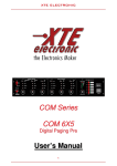
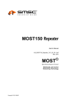
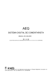
1
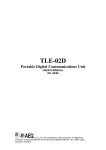
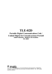
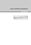
MPAC-02 Dual Channel Portable Audiocodec Audiocodec Portátil de Doble Canal ED. 08/99 A.E.Q., S.A. the manufacturer of this equipment, is “Registered Company”number ER-080/1/96 conforming to the AENOR UNE EN - ISO - 9001 quality assurance standard. INDEX 1. DESCRIPTION OF THE EQUIPMENT 1.1. BASIC DESIGN CONCEPTS 1.2. SPECIFICATIONS 1.3. FUNCTIONAL DIAGRAM 2. POWER SUPPLY 2.1. GENERAL 2.1.1. UNIT POWER SUPPLY 2.1.2. SWITCHING ON 3. INSTALLATION AND WIRING 3.1. DESCRIPTION OF THE FRONT PANEL 3.1.1. MICROPHONE INPUTS 3.1.2. LINE INPUT CHANNEL (TAPE-RECORDER INPUT) 3.1.3. MIC/TAPE SWITCH 3.2. DESCRIPTION OF THE REAR PANEL 3.3. DESCRIPTION OF THE LOWER PANEL 4. DESCRIPTION OF CONTROLS 4.1. CONTROL PANEL 4.2. COMMENTATOR CONTROL SECTION 4.3. MIC/TAPE SECTION 4.4. VISUALISATION AND USER INTERFACE CONTROL SECTION 4.5. DIALLING AND CHANNEL SELECTION SECTION 5. ISDN MODE USER INTERFACE 5.1. AUTOMATIC START-UP MODE 5.2. MANUAL START-UP MODE 5.2.1. ACCESS TO THE ‘PHONE BOOK 5.2.2. ACCESS TO RECALL 5.2.3. ACCESS TO CODIFICATION CHANGING 5.2.4. ACCESS TO START-UP CONFIGURATIONS 5.2.5. MANUAL DIALLING 5.2.6. CALL GENERATION 5.2.7. CONNECTION ESTABLISHED 5.3. GENERATION OF DTMF TONES FOR REMOTE CONTROL 6. TLE MODE USER INTERFACE 6.1. START-UP 6.2. EXTENDED OPERATION MODE 6.3. ACCESS TO THE ‘PHONE BOOK AND RECALL 6.4. CALL GENERATION 6.5. GENERATION OF DTMF TONES FOR REMOTE CONTROL 7. UPGRADING THE INTERNAL SOFTWARE (FIRMWARE UPGRADE) 7.1. SYSTEM DESCRIPTION 7.2. REQUIREMENTS OF THE PC USED FOR UPGRADING 7.3. CONNECTIONS FOR CONTROL COMPUTER 7.4. FIRMWARE UPGRADING 8. TECHNICAL SPECIFICATIONS APPENDIX 1: GUIDE TO RAPID USE 1.1. TO ESTABLISH COMMUNICATION 1.1.1. CTN MODE 1.1.2. ISDN MODE 1.2. EQUIPMENT USE ONCE COMMUNICATION IS ESTABLISHED APPENDIX 2: COMPATIBILITY WITH TELOS AND CCS AUDIOCODECS. APPENDIX 3: AEQ WARRANTY MPAC-02 Dual Channel Portable Audiocodec 2 1. DESCRIPTION OF THE EQUIPMENT 1.1. Basic design concepts The AEQ MPAC-02 is a portable multiformat communications unit, that in a single unit offers a complete collection of all the tools necessary to establish an audio and data link between the studio and remote location, with the best possible sound quality and ease of use, independent of the type of communication line. The equipment permits two-channel audio communication, one for the Program and the other for Co-ordination, using a single line, and is equipped with independent listening and level controls for each channel. Using the Automatic Start-Up System, it is possible to completely program the mode the unit will adopt on start-up. In this way, the technician can define all the communication parameters, including telephone numbers, and the commentator only has to select the switch on the rear panel that corresponds to the required configuration. When connecting the power supply automatically generates calls to the pre-set numbers. 1.2. Specifications: • Three microphone and one micro/line inputs, with COMBO connectors for XLR3 and Jack. • Three stereo headphone outputs, with independent level controls for left and right outputs. • Independent analogue mix level control for each input channel. • Mixing Compressor/Limiter. • Independent monitor selector for each of the three headphone amplifiers. The signals available are: - Program - Program return - Co-ordination - Co-ordination return Each signal can be sent, independently, to the left ear, right ear, both ears, or neither. • Independent dialling for each channel B, when using ISDN, with extension number capacity (where this is available). • In 64 Kbps modes, it is possible to make the codification algorithm of each channel B independent. • Display screen (2 lines X 24 characters). Indication of state, numbers dialled, telephone book and menu options. • A line output for each audio channel, with selection of send, return or both. • Access to the co-ordination circuit, with automatic Program disconnection, using a simple button. • Line outputs, with selection for return, send or both, for each audio channel. • Extended or Normal mode Operation (analogue lines). • DTMF tone generation, to control remote equipment. • 2 directed line inputs, one to the right and the other to the left earpiece of all the headphones. The left input can be added to the Program Go circuit; the right input can be added to the Coord Go circuit. • Analogue access to the Program and Co-ordination audiocodecs, with the possibility of using them as inputs for auxiliary return, Ambient Sound signals or public address for stereo transmissions. • Up to 30 different microswitch selectable configurations may be defined and stored, which can be automatically activated when the equipment is switched-on. • Available code algorithms: G.711, 64Kbps, 3.5KHz audio G.722 Statistical, 64Kbps, 7KHz audio G.722 H.221/H.242, 64Kbps, 7KHz audio LD-Extend, 15 KHz mono audio with low delay /128 Kbps ISO/MPEG LII mono 24 KHz, 64Kbps, 11KHz audio ISO/MPEG LII mono 32 KHz, 64Kbps, 10.5KHz audio ISO/MPEG LII mono 48 KHz, multiplexing J.52/IMUX, 128 Kbps, 20KHz audio ISO/MPEG LII Joint Stereo 48KHz, multiplexing J.52/IMUX, 128Kbps, 15KHz audio stereo ISO/MPEG LII Dual 32 KHz, multiplexing J.52/IMUX, 128Kbps, 10.5KHz audio dual MPAC-02 Dual Channel Portable Audiocodec 3 1.3. Functional diagram Schematic functional diagram of the Audio Codec. MPAC-02 Dual Channel Portable Audiocodec 4 The signal generated in each of the four channels (3 microphone and 1 micro/line) pass to the mixer circuits (Program or Co-ordination), and then, after passing through a limiter, are sent to the A/D converters on one hand, and the foldback circuits on the other. When a commentator wishes to speak to the studio, the ‘send to co-ordination’switch is pressed (CHANNEL COORD), which disconnects the Program circuit signal and sends it to the coordination circuit. The foldback circuits allow each commentator to select from the following signals for monitoring in their left or right earpiece at will: Program send (PROGRAM GO), Program return (PROGRAM F’BACK), Co-ordination send (COORD. GO) and Co-ordination return (COORD. F’BACK). The "CHANNEL ON" push-button allows the signal from the commentator to be sent to the Program circuit, provided that it is not already being sent to Co-ordination. The channel level is adjusted by the Mix Level potentiometer. The signal, once it has been limited, passes to the analogue-digital converters and is processed in the DSP. These are programmed for transmission by ISDN or CTN (Commuted Telephone Network). In the former case, the signals reach the TA (terminal adapters) or V35/V24 interface which are controlled by the communication controller, this accepts user instructions entered through the keyboard with this information being shown on the alphanumeric display. In the latter case, the signals are sent to the CTN telephone socket through the D/A converter instead of the ISDN adapters (TA or V35/V24). In both cases, a return signal (which may be two signals when using ISDN) travels in the reverse direction from the communication interface to the DSP, from where it passes to the D/A converters that generate the Program and Co-ordination return signals. These signals may be heard in the commentator’s headphones as they are being sent to the corresponding outputs. The Audiocodec in turn has a data port, to send and receive auxiliary data channels, and a control port for equipment configuration and upgrading. MPAC-02 Dual Channel Portable Audiocodec 5 2. POWER SUPPLY 2.1. General The power supply connector (1) as well as the on/off switch (2) are found on the rear panel of the unit. 2 1 2.1.1. Unit power supply Power is supplied to the equipment through the connector marked DC-INPUT using the power supply unit delivered with the unit. The equipment accepts DC supplies between 12 and 35 V. Power consumption is between 1800mA at 12 volts and 600mA at 35 volts. The power supply unit supplied with the equipment, or an alternative unit capable of delivering the correct voltage and current, must be used. AEQ MPAC-02 uninterrupted power supply system: The AEQ power supply supplied with the equipment includes a battery sufficient to allow approximately 30 minutes operation in the event of a network power supply failure. The power supply unit accepts inputs between 90 V and 264 V at 50/60 Hz. The power supply connects to the electricity network and an on/off switch is situated over the network input. The cable supplied with the power supply unit is fitted with a standard pin plug, which is lockable to prevent accidental disconnection. 2.1.2. Switching on Before connecting the power supply ensure the on/off switch is in the OFF position. Once the lockable plug is correctly connected to the unit, it should be connected to the network supply. Turn the AEQ power supply unit on/off switch to the ON position. Turn the power supply switch to ON. If all the previous steps have been correctly followed, the display will illuminate, indicating that the equipment is receiving power. MPAC-02 Dual Channel Portable Audiocodec 6 3. INSTALLATION AND WIRING To clarify the installation and wiring process it is necessary to be familiar with the connectors and configurable elements (on the front and rear panels). 3.1 Description of the front panel A series of combo XLR3-Jacks (1) are found on the front panel, one is connected to each channel of each input. This type of connector allows the connection of male XLR3 or ¼”male telephone type jack plugs, therefore admitting balanced or asymmetric signals. The commentator channels are provided with ¼”stereo telephone Jacks (2), for the connection of a headphone. The Mic/Tape channel possesses a micro/line level selector switch (3). 3.1.1. Microphone Inputs (1) The microphones are normally supplied with the appropriate connectors for direct connection to the Audiocodec. The connector wiring is shown below: XLR connectors ¼” Jack connectors 1: ground 2: microphone V+ 3: microphone V- sleeve: ground tip: microphone V+ ring: microphone V- 3.1.2. Line Input A cable with either a male XLR3 or ¼”stereo Jack must be used. The connector wiring is the same as that for the microphone inputs. 3.1.3. MIC/TAPE Switch (3) To select microphone input level, the switch is set to the rest position (switch button out), and to select line input level, the switch is set to the activated position (switch button in). MPAC-02 Dual Channel Portable Audiocodec 7 3.2. Description of the rear panel 13 12 14 10 2 8 9 11 7 6 1 3 5 4 The numbered elements and their use are described in the following selection. (1) (2) (3) (4) (5) (6) (7) (8) (9) (10) (11) (12) (13) (14) Output connectors (OUT 1 and 2) for Co-ordination and Program sends and returns respectively. XLR3 Male Switches (OUT 1/2 SELECT) to obtain at the output: the send signal (GO), return signal (F’B) or both (send + return) from the Co-ordination (CC) and Program (PRG) circuits respectively. Input connectors for local left channel foldback (LOC F'B LEFT) and right channel foldback (LOC F’B RIGHT). XLR3 Female Switches for sending these signals to the Program send (ENABLE MIX TO PROGRAM GO) and Co-ordination send (ENABLE MIX TO COORD GO) respectively. V35/V11 or V24 interface. Sub-D25 Female RS232 control port (CONTROL PORT). Sub-D9 Female RS232 data channel port (DATA CHANNEL PORT). Sub-D9 Female Mode selector switch (MODE SELECT) ISDN (ISDN) – Analogue Telephone Line (ANALOG TELEPHONE LINE). RJ45 ISDN line connector. RJ11 Analogue Telephone Line (CTN) connector. Configuration microswitches (STARTUP CONFIGURATION). Power supply connector (DC-INPUT). Fuses. Power supply switch (ON) Co-ordination and Program send and return output connectors (OUT 1 and 2): The output cables must be connected to the Audiocodec using female XLR 3-pin connectors. The connector wiring is shown below (balanced or unbalanced depending on the receiver inputs): Balanced outputs: 1: Ground 2: Output V+ 3: Output VUnbalanced outputs: 1: Output V- and Ground 2: Output V+ 3: Output V- and Ground MPAC-02 Dual Channel Portable Audiocodec 8 Local listening input connectors left (LOC F’B LEFT) and right (LOC F’B RIGHT). The input cables must be connected to the Audiocodec using male XLR 3-pin connectors. The connector wiring is shown below (balanced or unbalanced depending on the receiver inputs): Balanced inputs 1: Ground 2: Tape V+ 3: Tape VUnbalanced input 1: Tape V- and Ground 2: Tape V+ 3: Tape V- and Ground V35/V11 or V24 Interface: DB25 connector: Admits 2 types of external TA: V35 interface (V11): Uses unbalanced asynchronous control signals, while synchronous clock and data signals are balanced. V24 interface: This is a synchronous RS232. The active contacts are: V35/V11 Clock (RCX) V + Clock (RCX) V TX V + TX V RX V + RX V Common (V35/V11 – V24) DTR (Data Terminal Ready) CD (Carrier Detect) GND CTS (Clear to send) RTS (Request to send) V24 TX RX Clock (RXC) PIN 13 14 11 10 21 19 PIN 20 8 7 5 4 PIN 2 3 17 MPAC-02 Dual Channel Portable Audiocodec 9 Connections for Control (CONTROL PORT) and Data (DATA CHANNEL PORT) (RS232 ports) The unit has two female DB 9 chassis mounted connectors for configuration and transmission of auxiliary data in conjunction with an external computer communicating through RS 232 protocol (a cable fitted with male connectors must therefore be used). The active contacts are: TX RX GND 2 3 5 For details of the PC serial communication port, consult the user manual supplied with the computer. RJ45 chassis connector wiring The RJ 45 connector connects the terminal adapter, which is included in the equipment, with the ISDN access point (Network terminal). This connector wiring is standard according to the following diagram. FRONT VIEW For connection to the ISDN line socket the cable supplied with the equipment, or similar, must be used. Cable Number Connections 1 2 3 ---------Tx V+ 4 ---------Rx V 5 ---------Rx V+ 6 ---------Tx V 7 8 RJ11 chassis connector wiring: Connection to the telephone line is by 4 contact RJ11 type connector. The telephone line must be connected according to the standard for RJ11 connectors (using the two centre contacts, 2 and 3). For connection to the telephone line socket the cable supplied with the equipment, or similar, must be used. Selector Switch for ISDN-Analogue Telephone Line Mode (MODE SELECT ISDN/ANALOG TELEPHONE LINE): This selects the required line type (ISDN - CTN). Important: To change the line type selection the equipment must be switched-off and restarted with the new configuration. MPAC-02 Dual Channel Portable Audiocodec 10 DIP Microswitches Eight DIP microswitches, numbered 1 to 8, are incorporated in the unit. These are accessed from the rear panel. Each microswitch functions as follows: Microswitch Function 1 None 2 Multiplexing (J.52/IMUX) 128Kbps modes 4-8 Automatic start-up configurations All changes to the microswitch positions to modify the start-up configuration must be made before starting the unit (with the unit switched-off). Alterations made to the microswitch positions once the unit is in operation will have no effect and will not change the current configuration. • The selection of multiplex mode for the 128 Kbps channels is performed using microswitch 2: the up position selects IMUX; the down position selects J.52. The multiplex mode is shown in the LCD panel. See also Appendix 2. • Automatic start-up function configurations: Allow the unit to start-up using predetermined pre-programmed parameters (code, numbers to dial, etc.). The unit has two pre-programmed software configurations available (configuration C00 – Test mode, and configuration C01 – Manual Start-up mode) these cannot be modified. The remaining 30 configurations (C002 – C031) are freely available to the user. Important: Check that your AEQ MPAC-02 is not set in Test mode. Configuration of microswitches 4 - 8 for access to the automatic start-up configurations: Conf. C00 * C01 * C02 C03 C04 C05 C06 C07 C08 C09 C10 C11 C12 C13 C14 C15 4 0 0 0 0 0 0 0 0 0 0 0 0 0 0 0 0 5 0 0 0 0 0 0 0 0 1 1 1 1 1 1 1 1 6 0 0 0 0 1 1 1 1 0 0 0 0 1 1 1 1 7 0 0 1 1 0 0 1 1 0 0 1 1 0 0 1 1 8 0 1 0 1 0 1 0 1 0 1 0 1 0 1 0 1 Conf. C16 C17 C18 C19 C20 C21 C22 C23 C24 C25 C26 C27 C28 C29 C30 C31 4 1 1 1 1 1 1 1 1 1 1 1 1 1 1 1 1 5 0 0 0 0 0 0 0 0 1 1 1 1 1 1 1 1 6 0 0 0 0 1 1 1 1 0 0 0 0 1 1 1 1 7 0 0 1 1 0 0 1 1 0 0 1 1 0 0 1 1 8 0 1 0 1 0 1 0 1 0 1 0 1 0 1 0 1 (1 = ON, microswitch in the ‘up’position; 0 = OFF, microswitch in the ‘down’position) * Pre-set configurations, these cannot be modified by the user. MPAC-02 Dual Channel Portable Audiocodec 11 Power supply: Power is delivered to the Audiocodec by the AEQ MPAC-02 Uninterrupted Power Supply System, or another suitable power supply, through the DC-INPUT connector DC Voltage: 12 to 35 V Polarity: V+ : centre pin; V- : exterior Current: 1.7 A @ 12V, less at V > 12V Connector: Standard cylindrical DC, 2 mm internal, 6 mm external Power consumption: Approx. 22W Fuses: Various types (depending on the power supply voltage to be used, calculated by IFUSE ≅ 22W / Vdc supplied): Examples at the extremes: - 12V/1.8A Slow blow - 35V/0.6A Slow blow 3.3 Description of the lower panel The following elements are found on the lower panel: - 2 Trimmers for analogue input sensitivity adjustment of the Local Return Left (LOC F’B LEFT) (VR1) and Local Return Right. (LOC F’B RIGHT) (VR2). MPAC-02 Dual Channel Portable Audiocodec 12 4. DESCRIPTION OF CONTROLS 4.1. Control Panel From the operational point of view, the control panel is divided into four sections: • Commentators control section: COMMENTATOR 1, 2 and 3. • Mic/Tape Section • Visualisation and Control Section • Dialling and Channel Selection Section Fig. 4.1 Position of the control panel elements. MPAC-02 Dual Channel Portable Audiocodec 13 4.2. Commentator control section: The figure in the left column shows the different controls associated to each of the three commentary channels: COMMENTATOR 1, 2 and 3. • CHANNEL COORD. Disconnects the commentary microphone from the Program circuit and connects it to the Co-ordination circuit. Pressing the button again disconnects the Co-ordination circuit and reconnects it to the Program circuit (when the channel was previously connected to Program). Send to Headphones Control Switch: These press-buttons route the corresponding signals to the commentator’s headphones. If the button is pressed repeatedly, the signal is routed to the earphones in the following order: Left, right, both or neither of the two, the chosen option is indicated by the on/off status of the LEDs associated with each earpiece. • PROGRAM GO. Is the foldback from the Program circuit. The local mix signal is heard. • PROGRAM F’BACK. Is the foldback from the Program Return Circuit. The return signal from the central receiver is heard. • COORD GO. Is the foldback from the Coordination circuit. The local mix signal is heard. • COORD F’BACK. Is the foldback from the Co-ordination Return circuit. The return signal from the central receiver is heard. • CHANNEL ON. Activates the commentary microphone in the Program circuit. • MIX LEVEL. Controls the level of the commentary microphone in the mix (Program or Co-ordination). • LEFT and RIGHT. On the lower part of the module there are two level controls associated with the left and right earpiece outputs, to regulate the level in each of the commentator’s earpieces. MPAC-02 Dual Channel Portable Audiocodec 14 4.3. Mic/Tape Section The Portable Audiocodec can be used by three commentators and one guest simultaneously. The Mic/Tape section corresponds to the guest microphone input channel. The input can also be used for reproduction of a pre-recorded tape or for a line connection. • MIC/TAPE. A switch on the front panel selects the appropriate input gain and impedance for the connection of a dynamic microphone or a portable tape-recorder. The switch selection in the ‘out’ position is for a microphone input. The ‘in’position selects the line input. • OUTPUT SELECT. A Pushbutton that directs the output of the Mic/Tape channel to the Program output (PRG), Co-ordination output (CC), to both outputs, or to neither of the two. When this is pressed repeatedly these options are selected in the order as written, the status is indicated by the on/off condition of the LEDs associated with each output. • CHANNEL ON. Connects or disconnects the Mic/Tape channel to output circuit selected by the OUTPUT SELECT. • MIX LEVEL. Mic/Tape channel level control in the selected circuit. 4.4. Visualisation and User Interface Control Section The status of the AEQ MPAC-02 Portable Audiocodec (connection, codification, number dialled, etc.), as well as the configuration, can be visualised on the Display (2 lines X 24 characters). Access is gained to the various configuration menus, dialling, telephone book, etc. by using the four pushbuttons (Multifunction Keys) situated under the visual Display. The upper line of the Display is for user information and the lower line shows the function associated with each of the four Multifunction keys. The use of the Multifunction keys is explained in sections 5 and 6 “User Interface”. MPAC-02 Dual Channel Portable Audiocodec 15 4.5. Dialling and Channel Selection Section Disconnection of the Audiocodec from the various circuits (Program/ Co-ordination), as well as the selection of the channel to dial and generation of DTMF Tones for remote control and other uses, is executed from the Dialler and Channel Selection Section. • NUMERIC KEYBOARD. This is for entering the correspondent’s number. • PROG DISCONNECT. Pressing this button will disconnect the established Program output line. • COORD DISCONNECT. Pressing this button will disconnect the established Co-ordination output line. If the connection is in 128 mode, pressing either of the two switches will effect disconnection. • SELECT PROG/COORD CHANNEL. Pressing this button selects the desired output circuit (Program/Co-ordination) for making the connection, dialling or DTMF tone generation. The current selection is shown in the upper left corner of the Display. • HOLD FOR DTMF. DTMF tones for remote control and other functions can be generated by keeping this button pressed and using the numeric keyboard. The tones are then sent via the selected output (Program/Coordination) using the SELECT PROG/COORD CHANNEL key. (The audio signal in the corresponding output channel is muted during tone keying/generation). MPAC-02 Dual Channel Portable Audiocodec 16 5. ISDN MODE USER INTERFACE, Start-up: The unit starts-up by default (in either Automatic or Manual mode) with all channels muted, but retains the foldback Pre-selector configurations set on each channel before the equipment was switched-off. 5.1. Automatic Start-up Mode: There are 30 possible automatic start-up configurations that are selectable through 5 DIP switches on the back of the unit. Positions C02 to C31 may be user configured. For the implementation of automatic start-up configurations see section 3.2. “DIP Microswitches”. Position C00 .................... Test mode, used under Technical Service instructions Position C01 .................... Manual start-up mode (see section 5.2) Positions C02 to C31 … .... User defined modes The following window appears when the equipment is started with the DIP SWITCHES in any position between C02 and C31: MPAC-02 POWERED BY AEQ AUDIOCODEC ISDN Two seconds later, an informative window appears showing the loaded versions of different modules (Micro, DSP, and TA’s) of AEQ MPAC-02, , besides a PAUSE label. When the that label is pressed, it is sustituted with the label CONT, keeping the information of the versions until CONT is pressed. MCUV1.10 TA1V1.04 DSPV1.06 TA1V1.04 PAUSE If you have not pressed PAUSE, two seconds later the unit passes to the stand-by window (initial window), in which the configuration number is indicated, in this example number 2 (C02): CONFIGURATION NUMBER 2 AUTOMATIC MODE STARTUP Following this, a call is automatically generated to the number selected for the PROGRAM using the selected codification mode. Once the call is established, or a corresponding release message is seen, the unit automatically generates the call for the CO-ORDINATION circuit. Once the connection is established with the remote terminal, the connection established windows appear. If the configuration chosen for the automatic start-up is free the following window will appear: STARTUP CONFIGURATION SELECTED IS FREE indicating that there are no numbers to dial. One second later the unit automatically passes to the manual start-up mode stand-by window (initial window). MPAC-02 Dual Channel Portable Audiocodec 17 Finally if the automatically established communications are freed using the “PROG DISCONNECT” and/or “COORD DISCONNECT” keys, the unit will pass to the manual start-up mode stand-by window. MPAC-02 Dual Channel Portable Audiocodec 18 5.2. Manual start-up mode: ISDN Mode User Interface Flow diagram (manual start-up): This start-up mode is selected when the Start-up Configuration DIP switches are in position C01. MPAC-02 Dual Channel Portable Audiocodec 19 The following window appears on starting the unit: MPAC-02 POWERED BY AEQ ISDN MODE STARTUP Fig. 0 Two seconds later the stand-by or manual mode initial window appears: Fig. 1 ISDN G711 A-LAW 64 PRG P-BOOK RECAL CHCOD STRC In the initial window (1), the default codification mode selected for the establishment of the Program circuit connection appears on the top line of the display. The key “SELECT PROG/COORD CHANNEL” is used to change to the circuit desired for the connection. The message “ISDN G711 A-LAW 64 CC”will appear on the top line, indicating that the codification mode is active and that the Co-ordination circuit has been selected. The function associated with each of the multifunction keys appears on the bottom line of the display. “P-BOOK” “RECAL” “CHCOD” “STRC” In this situation the user can perform five operations: 1.- Activating “P-BOOK” (Telephone Book) displays the ‘phone book which is included in the unit. 2.- Activating “RECAL” (RECALL) displays the number and circuit used in the last conexion. 3.- Activating “CHCOD”(CHANGE CODIFICATION) accesses the window which allows the mode of connection codification to be changed. 4.- Activating “STRC” (SAVE CONFIGURATION) accesses the window which allows a new or existing modified start-up configuration to be saved. 5.- Finally, if the numerical keyboard is used in the stand-by state, the manual number composition window appears and the user can manually enter a telephone number and make a call. The following describes the use of the above functions: 5.2.1. Access to the ‘phone book On activating “P-BOOK”the following window appears: A001 OK LABEL UP DOWN (2) ESC The first entry stored in the ‘phone book’s non-volatile RAM memory appears on the upper line of the display. Each ‘phone book entry has three fields: Position number field: A001......A256, to designate the position of the entry in the ‘phone book. LABEL field: maximum 10 characters, to give a name to the entry. NUMBER field: maximum 20 digits, to save the telephone number. If the ‘phone book registry is empty only the registry number is displayed, and the label field does not appear. The user can select the desired entry by using the “UP” and “DOWN” keys to pass through the 255 available registers. Using the “DOWN” key will display entry number 2, and using the “UP” key will display entry number 256 (reserved). Note: The 256 register of the phone book entry is reserved for future applications. MPAC-02 Dual Channel Portable Audiocodec 20 Pressing “ESC”will return to the stand-by window (1). The “OK”key validates the entry selected by the user and passes to window (3): A001 DIAL LABEL EDIT NUMB PRG ESC (3) The “DIAL” key is pressed to establish the connection The unit dials the corresponding number via the selected circuit (shown in the top right corner), the said circuit can be selected using the “SELECT PROG/COORD CHANNEL”key. Activating “NUMB”displays the telephone number associated with this ‘phone book entry (3’). TELEPHONE NUMBER (3’) ESC Pressing “ESC”will return to the previous window (3). The “EDIT”key summons the edit/modify window for the selected entry. First, the number associated to the entry in question is edited (4). TELEPHONE NUMBER OK ⇐ ⇒ DEL (4) The telephone number associated to the selected ‘phone book registry appears on the top line of the display. If the said registry is empty, the top line of the display will be blank (the cursor position is marked by the corresponding display position blinking. Initially the cursor is displaced to first position on the display). The numerical keyboard enters the number directly onto the top line of the display and automatically advances the cursor. The “⇐ “ and “⇒ “ keys move the cursor backwards or forwards respectively to modify the numbers which have been introduced. The “DEL”key erases the digit above the cursor and advances the cursor. Finally, the “OK”key validates the number and passes to the label edit window (5). A001 OK LABEL UP DOWN SEL (5) If the registry is empty, the registry number is shown on the top line of the display and the cursor blinks in the first modifiable position, with the “LABEL”field remaining blank. The characters which form the label are selected using the “UP” and “DOWN” keys to pass through the table containing all the alphabetical and special characters such as blank space (““) and hyphen (“-“). (“ , - , A, B,...,Z). When starting from an empty registry, pressing “DOWN”will show “-“and pressing “UP”will show “Z”. It is only necessary to pause for one second after pressing “UP” or “DOWN” to select the desired character and pass to the next position in the label. The cursor automatically advances to the next position. The numerical keyboard is used to introduce the “*” or the “#” and numerical characters into the label, in this case the cursor will advance automatically. MPAC-02 Dual Channel Portable Audiocodec 21 If it is necessary to make corrections or modifications to one or more characters in the label, the correction window (5’) is opened using the “SELFU”key. A001 LABEL CHSEL ⇐ ⇒ ( 5’) DEL The cursor is moved to the character to be modified using the “⇐ “and “⇒ “keys. The “DEL”key deletes the character. “CHSEL”is used to return to the previous window (5) and the character above the cursor in (5’) is modified. Finally, in window (5), the label associated with the selected ‘phone book register is definitively validated using the “OK” key, and is stored in non-volatile RAM memory and the stand-by window (1) appears. 5.2.2. Access to Recall Activating the “RECAL”key from the stand-by state (1) opens the recall window (6). LAST NUMBER & CHANNEL USED DIAL ESC (6) The last number that was dialled and connected, together with the circuit used to establish the connection (PRG/CC), appears on the top line of the display. On initial start-up, the top line will be empty, numbers are not stored in non-volatile memory when the equipment is switched-off. If you like, before pressing the DIAL key, you can change the connection circuit. Activating the “DIAL”key dials the number displayed through the circuit indicated. The codification mode previously selected by the user, or the default setting, will be used for the communication. The “ESC”key will return the unit to the status shown in (Fig. 1). MPAC-02 Dual Channel Portable Audiocodec 22 5.2.3. Access to codification changing Activating the “CHCOD” key when in the stand-by state (1), opens the codification change window (7): ISDN G711 LAW-A 64? OK UP DOWN (7) ESC The user can view the different codification modes available by using the “UP” and “DOWN” keys to pass through the table: 64 Kbps Modes: ISDN G711 A-Law 64................. Law A, 64Kbps, 3.5KHz audio ISDN G711 µ-Law 64 ................. Law µ, 64Kbps, 3.5KHz audio ISDN G722 STAT 64.................. G722 Statistical, 64Kbps, 7KHz audio ISDN G722 H221 64 .................. G722 H221/H242, 64Kbps, 7KHz audio ISDN MPEG 32MON 64............. MPEG1 LII 32KHz MONO, 64Kbps, 10.5KHz audio ISDN MPEG 24MON 64............. MPEG2 LII 24KHz MONO, 64Kbps, 11KHz audio 128 Kbps Modes: ISDN AEQ LD-EXT 128 ............. Mode AEQ Extended, 128Kbps, 15KHz audio ISDN MPEG 48MONO 128 ........ MPEG1 LII, 48 KHz MONO, 128Kbps, 20KHz audio ISDN MPEG 48JSTR 128 .......... MPEG1 LII, 48 KHz Joint stereo, 128Kbps, 15KHz audio ISDN MPEG 32DUAL 128.......... MPEG1 LII, 32 KHz Dual, 128Kbps, 10.5KHz audio dual (If the “DOWN” key is pressed in the state represented by (Fig.7) the legend “ISDN G711 µ− LAW 64“ will appear on the top line of the display, and if “UP” is pressed “ISDN MPEG 32DUAL 128”will appear). Next to the label of each mode, a blinking quotation mark appears. There is one more codification mode selected when you press OK button in the next window: ISDN AUTOMATIC MODE ? OK UP DOWN PRG ESC This is the Automatic code Searching mode: the unit works as Slave and automatically detects the transmission code being used by the receiver and adapts accordingly (using the same code for transmission) If the unit works as Master, the user decides the transmission code mode to be used. It must be remembered that if a voice call is made (G711 codification), it forces the codification in the receiver, independently of the equipment being master or slave. Pressing the “ESC” key will return to the initial window without modifying the current codification setting. Pressing “OK”validates the selected codification mode and the stand-by window (1) will appear with the new codification mode being shown on the top line of the display and without the flashing block. For example, if “ISDN G722 STAT 64” is selected, the following will be seen on returning to the stand-by state: ISDN G722 STAT 64 PRG P-BOOK RECAL CHCOD STRC MPAC-02 Dual Channel Portable Audiocodec 23 5.2.4. Access to start-up configurations The AEQ MPAC-02 Portable Audiocodec allows the storage of up to 30 distinct ISDN start-up configurations in non-volatile RAM, which makes automatic start-up possible through the DIP microswitches on the rear panel. For details of microswitch configuration, see section 3.2 “DIP microswitches”. C02 to C31 (30) are user-defined configurations. Configurations C00 and C01 are reserved (Test Mode and Manual Start-up Mode) and cannot be edited or modified. Codification information and the number to use for each communication channel is stored in each configuration (Program - Co-ordination), each register consists of three fields (LABEL, NUMBER and CODIFICATION) for each channel (Program and Co-ordination). Therefore, in one configuration register it is possible to store one codification type with the number to dial for the Program channel using a specific label, and one codification type and number to dial for the Co-ordination channel with a different label. Important: Given that 128Kb codifications use both 64Kb channels, it is only possible to store the information related to the channel (Program) and (Coordination). The following explains the configuration register edition/modification procedure. Given that editing the fields in a register is performed similarly to editing the ‘phone book, the procedure will be roughly explained, with those aspects which differ to the edition/modification of the ‘phone book being explained in more detail. From the stand-by status (1), pressing the ”STRC”key will open window (8): C02 OK LABEL UP DOWN PRG ESC (8) The first configuration register will appear on the top line of the display, with the corresponding label for the Program channel. The “UP” and “DOWN” keys are used to select the register number required for display or modification and storage in RAM. The “DOWN” key will present register C03, and the “UP” key will present register C31. If you keep held down any of these keys, you will get fast movement through all the registers. The “SELECT PROG/COORD CHANNEL” key is used to select the channel required for display/edition (Program/Co-ordination). Once the register and desired channel have been selected, the selection is validated with the “OK”key and passes on to the edit window (9). C02 LABEL EDIT CODIF NUMB PRG ESC (9) The “ESC”key will return to the stand-by state (1). Note: As the process of editing/modifying a start-up configuration is the same for both Program and Co-ordination, only the Program example is referred to here. Using the “ESC”key returns to window (8). The codification and ISDN number associated to the selected Program circuit start-up configuration are visualised using the “CODIF” and “NUMB” keys. Windows similar to those of the ‘phone book appear (3’). For example: “CODIF” “NUMB” ISDN G722 H221 64 PRG ESC 916857020 ESC MPAC-02 Dual Channel Portable Audiocodec 24 The “ESC”key will return to window (9). The “EDIT” key is pressed to pass on to the edition/modification of the selected start-up configuration register. Editing is performed sequentially in a similar way to the ‘phone book register, in the order: Number (10), Label (11) and Codification (12). Number (10): The number is entered using the numeric keyboard. 916857020 OK ⇐ ⇒ (10) DEL Label (11): The label is edited using the multifunction keys. CO2 OK AEQ-ISDN1 UP DOWN PRG SEL (11) Codification (12): The codification is selected using the “UP” and “DOWN”, keys to pass through the Codification Mode table as detailed in the previous section 5.2.3 “Access to codification change”, and the selection is confirmed using the “OK”key. When the codification is validated, the edited start-up configuration is stored in non-volatile RAM and stand-by status is resumed (1). ISDN G722 H221 64 PRG OK UP DOWN (12) 5.2.5. Manual dialling If the numeric keyboard located on the front of the unit is used when in stand-by status, the dialling window will open (13): 9______ DIAL <DEL PRG ESC (13) The number will appear on the top line of the display as it is entered. The circuit to be used to make the call can be selected using the “SELECT PROG/COORD CHANNEL”key. Using the “<DEL”key will delete the last digit entered. Pressing the “DIAL”key will initiate the call to the number that has been manually entered. The “ESC”key may be used to return to the stand-by window (1) if it is not desired to establish communication at this time. 5.2.6. Call generation Activating the “DIAL”key in any of the windows represented by Fig. (3), (6) and (13), initiates the call generation process, which results in the display of a release of call, or successful connection message. When communication is initiated, window (14) will appear: CALL IN PROGRESS (14) MPAC-02 Dual Channel Portable Audiocodec 25 If the communication continues successfully and connection is established the connection established window (15) will open. PRG CONNECTED CODIF DATCHN SYNC. (15) VU This window is detailed in the following section. If on the other hand the connection cannot be established, the user will be informed of the reason for the failure. The following call release messages are issued by the equipment: i) ERROR: An internal error has occurred in the call generation process. ii) CHANNEL NOT AVAILABLE: An attempt is being made to establish communication through a channel that is already occupied in the unit. iii) NO ISDN AVAILABLE: An attempt has been made to establish communication when there is no ISDN line available. iv) DESTINATION BUSY: The remote terminal is occupied. v) NO ANSWER: The remote terminal has not responded to the incoming call. vi) CALL REJECTED: The network has rejected the call, this includes all the remaining possible causes of release. vii) CALL NOT CONNECTED: The waiting time set for the unit to establish connection with a remote terminal has expired. The equipment will return to the stand-by window (1) following the emission of any of these release messages. 5.2.7. Connection established The following message will appear in the display after window (14) if the connection is established: CALL CONNECTED (14’) and the following window will appear one second later: PRG CONNECTED CODIF DATCHN (15) VU If the call is established through the Co-ordination circuit, “CC. CONNECTED SINC”will appear on the top line of the display. SINC/NON SINC: The connection is established and sincronized/non sincronized. CODIF: Opens the codification window. DATCHN: Opens the window for the establishment of auxiliary data channel. VU: Opens the VU-meter mode window. MPAC-02 Dual Channel Portable Audiocodec 26 5.2.7.1. Data channel: This is a transparent bi-directional point-to-point 1200 baud channel. For the channel to operate correctly, the transmission configuration should be set to: 1200 bauds No parity 8 data bits 1 stop bit The data channel can be established in relation to the codification mode being used in the established connection. - An auxiliary data channel may be established in the following modes: Modes 128: • Modes 64: -MPEG 48 MONO 128 -G722 H221 64 -MPEG 48 JSTR 128 -MPEG 32 MONO 64 -MPEG 32 DUAL 128 -MPEG 24 MONO 64 - Modes which do not accept auxiliary data channels: • The remaining modes shown in the table in section 5.2.3 The following message will be displayed for one second if the ”DATCHN”key is operated in window (15) while using a mode that does not allow the establishment of a data channel: DATA CHANNEL NOT AVAILABLE and then return to window (15). If the “DATCHN”key is activated while using mode 64, which permits the establishment of a data channel, window (16) is opened: PG: TXof RXof CHANN RX CC: TXof RXof TX ESC (16) Pressing the “ESC”key will return to window (15). When window (16) is opened, the cursor appears on the letter “P” of Program circuit, indicating that this channel is selected by default. The other channel may be selected by pressing the “CHANN” key, and the cursor will pass to the letter “C” of Co-ordination circuit. Pressing the “Rx” and “Tx” keys activates (On) or deactivates (Off) the transmission (Tx) or reception (Rx) of the corresponding data channel to the channel that is currently active. Given that there is only one data channel available, only one data transmission and one data reception can be established simultaneously, that is to say, if one channel (e.g. Program) is transmitting, the other channel (Co-ordination) can only receive, and vice-versa; if one channel is simultaneously transmitting and receiving data, the other cannot be used for either transmission or reception, because the data channel is already occupied. If this is the case and an attempt is made to activate the other channel to transmit or receive data, the equipment will reject the request and display the window: MPAC-02 Dual Channel Portable Audiocodec 27 DATA CHANNEL BUSY If the codification in use for the connection is a 128 mode that permits the use of a data channel, the window that appears will be different to (16), being: PG: RXof RX CC: TXof TX (16’) ESC There is no option for the selection of the direction of the data channel in 128 mode, because only one communication channel exists. Window (16’) is simplified and Program is associated to the reception of data and Coordination to the transmission. The “Tx” and “Rx” keys activate or deactivate the transmission and reception of data respectively. Pressing the “ESC”key will return to window (15). 5.2.7.2. VU-meter mode: Pressing the VU key in window (15) will open the VU-meter window (17): PG: ¦¦¦¦¦¦¦¦¦ ƒΦ ƒƒƒ O CC: ¦ ¦¦¦¦¦¦ ƒƒΦ ƒƒƒ O (17) ESC The output levels from the two channels (Program and Co-ordination) are represented by ” ¦ “ characters. If the output signal level is below –22dBu the ”¦ ” character will not appear in the display. Each “¦ “ character represents a step of 2dB. The “Φ ” represents 0dBu level. Levels above “Φ ” are shown as +2, +4, +6dBu and finally the character ”O” which represents Program signal saturation level (+18dBu). To avoid saturation, it is advisable not to exceed the recommended input levels. The Program (PG) signal line output level is shown on the top line of the display, and the Coordination (CC) signal line output level on the bottom line. “ESC”is used to return to window (15). The “PROG DISCONNECT” and/or “COORD DISCONNECT” keys are used to terminate the connection, according to the communication channel (Program/Co-ordination) in window (15) it is desired to disconnect. The corresponding message will be displayed: and the initial stand-by window (1) will return. PRG. DISCONNECTED CC. DISCONNECTED The same happens when the remote terminal terminates the connection. 5.3. Generation of DTMF tones for remote control. It is possible to generate and send DTMF tones to line to effect remote control operations when operating in ISDN mode and in connection established status (4). It is necessary to press and hold the “HOLD FOR DTMF”key and at the same time press the corresponding digit on the keyboard. The audio Program is cut during tone generation. DTMF dialling mode must be used to establish the call for this function to work correctly. MPAC-02 Dual Channel Portable Audiocodec 28 6. TLE MODE USER INTERFACE. TLE Mode User Interface Flow diagram: MPAC-02 Dual Channel Portable Audiocodec 29 6.1. Start-up: The equipment starts-up with all channels muted, but conserves the foldback Pre-selector configurations as set for each channel prior to switch-off. When the equipment is switched-on and TLE mode is selected by the switch on the rear panel, the following window will be displayed: MPAC-02 POWERED BY AEQ ANALOG MODE STARTUP MODE and two seconds later the analogue stand-by window (1) will appear: ANALOG TELEPHONE LINE OFFHK PULSE EXTEN P-BOOK (1) When the equipment is switched-on DTMF dialling and NORMAL operations are selected by default. Pressing the “PULSE”and “EXTEN” keys changes the dialling mode to PULSE and the operational mode to EXTENDED respectively. The stand-by window changes to show the new “DTMF”and “NORM”keys respectively (1’). However, the “PULSE/DTMF” and “EXTEN/NORM” keys do not indicate the actual unit status but only indicate the status selectable by the corresponding key. ANALOG TELEPHONE LINE OFFHK MFDT NORM P-BOOK (1’) 6.2. Extended operation mode. Typical telephone circuits have a limited band width between 300 and 4000 Hz. Unfortunately, the major part of voice energy is in frequencies below 300 Hz, and is lost during transmission over telephone lines. Telephone audio signals have their characteristic sound, the loss of voice body being the most notable, for this reason. The extended operation mode allows the transmission of frequencies between 50 and 300 Hz through telephone lines. To achieve this, the signal is subjected to a 250 Hz frequency shift before being sent, thereby improving the low frequency band quality of the signal received at the expense of the highest band. The bandwidth transmitted is, therefore, between 50 and 3750 Hz. The 250 Hz lost in the highest frequencies are not very significant given the logarithmic nature of audio frequency response. The frequency shift is performed by encoding the audio signal before it is sent to the telephone line. The suitably equipped receiver decodes the signal, that is to say, the frequency shift is reversed. The decoded signal contains the original band (50-3750 HZ) without suffering any type of degradation. In this way, a voice signal with improved clarity and depth is achieved, including during those communications that take place under the worst conditions. Switching between Extended and Normal mode is performed using the “EXTEN/NORM” key during TLE stand-by mode (1). MPAC-02 Dual Channel Portable Audiocodec 30 6.3. Access to the Phone Book and Recall: The ‘phone book is shared by both the equipment’s working modes (ISDN and TLE). Access is identical to that described in ISDN mode section 5.2.1 The differences are as follows: Pressing the “P-BOOK”key in stand-by (1) opens the ‘phone book and recall window (2). UL: (2) UP DOWN ESC The last number dialled is shown on the top line. If the ‘phone book is entered from start-up no number is displayed (2), if any calls have been made, the last number dialled (UL) will be seen, window (2’). UL: 6861300 OFFHK UP DOWN ESC (2’) Recall is effected using the “OFFHK” key. The “UP” and “DOWN” keys are used to enter the ‘phone book and pass through the 256 entries as explained in the ISDN section. The “OFFHK” key replaces the “DIAL”key used in ISDN mode. A001 LABEL OFFHK EDIT NUMB ESC (3) Pressing the “ESC”key will return to the stand-by state (1). 6.4. Call generation: Pressing the “OFFHK” (Off Hook) key in any window will produce a dialling tone. Windows (1), (1’), (2’) and (3). Activating the “OFFHK”key from any of these windows will open window (4). (4) ONHK PULSE EXTEN VU Dialling is automatic if the number is taken from the 'phone book, or is a recall which is shown on the top line of the display. Dialling can also be performed manually using the numeric keyboard. Pressing the “VU” key will open the VU-meter window to enable visualisation of the Program output level in the same way as in ISDN mode, except only one channel will be seen (5). PG: ¦¦¦¦¦¦¦¦¦ ƒΦ ƒƒƒ O ONHKPLSEONHK PULSE EXTEN (5) CONN If “ONHK” (On Hook) is pressed in windows (4) or (5) once the call is established, or during dialling, the call will be terminated and the unit will return to stand-by status (1). Pressing the “CONN”key will return to the previous window (4). 6.5. Generation of DTMF tones for remote control. It is possible to generate and send DTMF tones to line to effect remote control operations when operating in TLE mode and in connection established status (4). It is necessary to press and hold the “HOLD FOR DTMF” key and at the same time press the corresponding digit on the keyboard. The audio Program is cut during tone generation. DTMF dialling mode must be used to establish the call for this function to work correctly. MPAC-02 Dual Channel Portable Audiocodec 31 7. UPGRADING THE INTERNAL SOFTWARE (FIRMWARE UPGRADE): This section describes the procedure to upgrade the AEQ MPAC-02 Audiocodec internal software. 7.1. System description The system allows the internal software in the three basic MPAC-02 modules to be upgraded, i.e. the Microprocessor, Terminal Adapters (TAs) and Digital Signal Processors (DSPs). 7.2. Requirements of the PC used for upgrading The system requirements are determined by the Operative System in use: Windows 95 or Windows NT . These operative systems dictate the computer’s minimum processor and available RAM memory specifications. With Windows 95 the minimum configuration is a Pentium family processor with 16 MB RAM memory. The software installation requires 3 MB hard disk space and up to 20 MB for user configurations. A mouse and a free serial port are also required. 7.3. Connections for computer control A female connector, labelled “CONTROL PORT”, is mounted on the rear of the Audiocodec chassis for connection to an external computer communicating through RS-232 protocol. The PC is connected through its serial port. The connections are as follows: RX TX GND 2 3 5 The pins connecting the Audiocodec and PC are as follows: MPAC-02: DB-9 MALE PC: DB-9 FEMALE 2 -------------------------------------- 2 3 -------------------------------------- 3 5 -------------------------------------- 5 MPAC-02: DB-9 MALE PC: DB-25 FEMALE 2 -------------------------------------- 3 3 -------------------------------------- 2 5 -------------------------------------- 7 7.4 Firmware upgrading The operation to upgrade the firmware is very simple. A floppy disk is available for Firmware upgrading. Important: Ensure that the start-up configuration is NOT set to Test Mode. Also, the equipment cannot be used for any other operation, such as making a call etc., during the process of upgrading the Firmware. The upgrading procedure is as follows: Before commencing the upgrading process, the PC and AEQ MPAC-02 must be interconnected using the PC serial port and the AEQ MPAC-02 Control port as previously described. Once connected, open the floppy disk containing the Firmware upgrade. MPAC-02 Dual Channel Portable Audiocodec 32 Find the application “MPAC-02 Firmware Upgrade” and double click on the application icon, whereupon the following screen will be seen: Fig. 7.1. MPAC-02 Firmware Upgrade screen If communication is correctly established with the AEQ MPAC-02, the screen shows the three basic modules, the Microprocessor, Digital Signal Processor (DSP) and Terminal Adapters, each with the current Firmware version and date (e.g. Microprocessor - (Ver 1.00 08/05/98)). Luminous indicators in the bottom right hand corner of the screen display the state of communication between the PC and AEQ MPAC-02. (They should be green and blinking). The serial channel communication parameters are displayed in the bottom left hand corner of the screen. If communication is not established correctly, the user must indicate the port to be used for communication. The corresponding screen is: Access must be gained through the “File – Setup PC” menu to configure the corresponding communication port. Fig. 7.2. Without communication Fig. 7.3. File menu The “Setup PC” option opens a window that allows modification of the communications port. Note: this is the only recourse that may be modified. Important: The option “Constructor”in the File menu is exclusively for use by Technical Service and is not user definable. MPAC-02 Dual Channel Portable Audiocodec 33 Fig, 7.4. Configuration Once communication with the AEQ MPAC-02 is correctly established and the screen in figure 7.1 is visible, the module upgrading process can continue. In the installation directory, together with the Upgrade application, there are three files, each labelled according to the module software they contain: Micro, DSP and TA. The software upgrading process for each module is as follows (this operation is identical for all modules, therefore only one generic example is described): From the screen shown in figure 7.1 click on the required module for upgrading with the right mouse button, for example the Microprocessor. An option “Open”will be displayed. Fig. 7.5. Open option Select “Open”with the left mouse button. A window for the selection of the Upgrade file will open. The appropriate directory must be selected for each module, within which the upgrade file for each module can be found. MPAC-02 Dual Channel Portable Audiocodec 34 Fig. 7.6. Open Upgrade File Once the file with the latest software version is selected, the Upgrade window opens: Fig. 7.7. Upgrade Window The current MPAC-02 module software version is shown in the bottom left section of the window, and the version for the upgrade in the right. The “Upgrade”button is pressed to proceed with the software upgrade. A progress indicator appears that shows the time remaining to complete the process. MPAC-02 Dual Channel Portable Audiocodec 35 Fig. 7.8. Upgrading process It is possible to verify the firmware transmission after writing by clicking on the corresponding box in the Upgrade window before commencing the process. In this case, the program reads the upgraded version following installation. This verification process should not normally be necessary. Fig. 7.9. Verification MPAC-02 Dual Channel Portable Audiocodec 36 After writing (and verification when selected), the Upgrade program will confirm that the process has been successfully completed: Fig. 7.10. Upgrade successful. This process must be carried out for each of the three modules (Microprocessor, DSP and TA). MPAC-02 Dual Channel Portable Audiocodec 37 8. MPAC-02 TECHNICAL SPECIFICATIONS • Microphone inputs (transformer balanced): • Input impedance: >3KΩ • Nominal input level for PRG GO = 0dBu: -60dBu • Maximum input level for nominal adjustment: -34.5dBu • Input range for PRG GO = 0dBu: -70dBu ÷ -34.5dBu • Output variation limits for nominal input: -∞ ÷ +10dBu • Bandwidth: 20Hz ÷ 20KHz -1.3dB • EIN: (G= 60dB; Absolute noise = -60.5dBu) = -120.5dBu (with BPF) • EIN: (G= 70dB; Absolute noise = -52.5dBu) = -122.5dBu (with BPF) • Line input (transformer balanced): • Input impedance: >6K5Ω • Nominal input level for PRG GO = 0dBu: +1.5dBu • Maximum input level for nominal adjustment: +26dBu • Input range for PRG GO = 0dBu: -9dBu ÷ +26dBu • Output variation limits for nominal input: -∞ ÷ +10dBu • Bandwidth: 20Hz ÷ 20KHz -1dB • LOC F’B LEFT and RIGHT inputs (transformer balanced): • Input impedance: >6K5Ω • Nominal input level for PRG GO = 0dBu: 0dBu • Maximum input level for nominal adjustment: +26dBu • Range adjustment for PRG GO = 0dBu: -10dBu ÷ +10dBu • Bandwidth: 20Hz ÷ 20KHz -1dB • Outputs 1 and 2 (transformer balanced): • Output impedance: <75Ω • Nominal output level: 0dBu • Maximum output level: +16dBu • Absolute noise (with all sends cut): SEND (GO): -63dBu RETURN (F’BACK): -69dBu; -51dBu with all codecs activated • Headphone outputs: • Nominal load impedance: 2 x 600Ω • Nominal output level (potentiometer at maximum): +6dBu • Maximum output level: +7dBu • Output absolute noise (pot. at maximum, sends cut): -70dBu MPAC-02 Dual Channel Portable Audiocodec 38 • Output power (into 600Ω): 5mW • Crosstalk (20Hz ÷ 20KHz): • PROG - COORD (nominal adjustment): <-60dB • Headphones over microphone (nominal adjustment, pot. at max., microphone input load 200Ω): <-36dB • Telephone line interface: • Input / Output: Transformer • Impedance: 600Ω • Nominal input level: -10dBu • Nominal output level: - 6.5dBu • Bandwidth • Expander inactive (Normal mode): Telephone line: 300Hz ÷ 4000Hz -1dB Output PROG F’B: 300Hz ÷ 4000Hz -1dB • Expander active (Extended mode): Telephone line: 50Hz ÷ 3750Hz -1dB Output PROG F’B: 50HZ ÷ 3750Hz -1dB • Distortion (1KHz at nominal input and output levels): Telephone line: 0.15% Output PROG F’B: 0.25% • Absolute noise: Telephone line: -66dBu Output PROG F’B: -51dBu • Frequency extension: TX: +250Hz RX: -250Hz • Electrical echo suppression: Line Impedance 600Ω Signal source 1KHz. Adjusted for PRG GO = +15dBu Output PROG F’B: -49dBu (64dB rejection) • Approximate dimensions: • Width: 34.5 cm • Height: 10.3 cm • Depth: 30 cm • Weight: 6 Kg (approx.) MPAC-02 Dual Channel Portable Audiocodec 39 • AEQ MPAC-02 Uninterrupted Power Supply System: • Input voltage: 90 to 264 Vac, 50/60 Hz • Output voltage: 13.7 Vdc / 1.6 A • Autonomy: 30 minutes • Weight: 1300 gr. max. MPAC-02 Dual Channel Portable Audiocodec 40 APPENDIX I: GUIDE TO RAPID USE 1.1. To establish communication: Before making a call, and with the unit switched-off, select the analogue telephone line CTN (ANALOG TELEPHONE LINE), or ISDN digital line (ISDN) option. Selection of the required line mode is by the (MODE SELECT) switch found on the rear panel. 1.1.1. Analogue telephone line (CTN) Switch-on the unit and the display will illuminate with the message “ANALOG TELEPHONE LINE”. Manual call: • To make a call press the “OFFHK”key that appears in the display. • Enter the required telephone number using the numeric keyboard (the number will be shown in the LCD display). In this mode, the equipment selects both DTMF (multifrequency) dialling and NORMAL frequency response by default. These modes may be changed to PULSE and EXTENDED respectively by pressing the corresponding keys in the display. Automatic call (calling from the ‘phone book): • • • • Select the P-BOOK using the corresponding key in the display. Using the UP – DOWN keys, look for the required telephone number. Press the VALID key to select the required number. Press the OFFHK key to make the call. If the call is not established at the first attempt (line busy, no reply) in any call mode (manual or automatic), it is possible to redial by accessing the ‘phone book where the last number dialled will be stored in the first position. To disconnect the equipment from the line it is only necessary to press the ONHK button found in the display. 1.1.2. Digital line (ISDN) Before switching-on the equipment the microswitches on the rear panel must be configured for manual start-up: 3 and 8 in the “up”position and the remainder in the “down”position. Switch-on the unit and the display will illuminate with the message “ISDN G722 64 STAT“. When calls are made over ISDN digital lines, the AEQ MPAC-02 is capable of communicating through two independent 64Kb channels, one for program and the other for orders. Once connection is established in one channel, the second channel may be connected. The destination selector (SELECT PROG/COORD CHANNEL) situated on the left of the numeric keyboard must be pressed to select the desired channel (Program/Coordination) for the connection. The channel selected will be shown in the top right corner of the LCD display. By default, the Program will be passed to the channel used for the initial dialling, and Co-ordination to the second channel. MPAC-02 Dual Channel Portable Audiocodec 41 Manual call: • Select the necessary transmission codification (if not the one shown in the display) by pressing the corresponding CHCOD (Change Codification) key. • Press UP - DOWN to select the required code. The codification must be the same as used by the remote equipment for communication. • Press OK to set the selected codification. • Dial the desired telephone number using the numeric keyboard. • Press the DIAL key to initiate the dialling process. The message CALL IN PROGRESS appears in the display during the establishment of a call. If the communication is successfully realised, the message CALL CONNECTED will appear. If the call fails, an error message will appear indicating the possible cause. The dialling process for the second channel is the same as described above. Automatic call: • • • • Select the P-BOOK key in the display. Using the UP – DOWN keys, look for the required telephone number. Press the OK key to select the required number. Press the DIAL key to initiate the dialling process. . If the call is not established at the first attempt (line busy, no reply) and independent of the mode being used (manual or automatic), redial may be effected using the RECAL option where the last number dialled will be stored. To disconnect the unit from the corresponding line (CTN o ISDN), the button corresponding to the channel for disconnection (PROG DISCONNECT or COORD DISCONNECT) situated at the left of the numeric keyboard must be pressed. In ISDN 128Kb mode (using both 64Kb channels as one channel) pressing either of the two buttons will disconnect the equipment VU mode (VU-meter) may be selected to monitor the output signal level once communication has been established through either analogue CTN or ISDN digital line. 1.2. Equipment use once communication is established: The AEQ MPAC-02 Portable Audiocodec behaves like a small mixer. The equipment has three commentator channels, each with a microphone input, a control for microphone mix level, a headphone output with independent level controls for each earpiece, push-buttons to assign channels to the mix circuits (Program or Co-ordination), and pushbuttons to independently send the various signals available in the unit to the left and right earphones of the commentator. The Audiocodec also has a microphone/line channel for the connection of a fourth guest microphone, or the output from a portable tape-recorder, and has its own corresponding mix level control, as well as a send to mix circuit selector (Program, Co-ordination, both or none). MPAC-02 Dual Channel Portable Audiocodec 42 APPENDIX 2: Compatibility with TELOS y CCS audiocodecs. For the AEQ MPAC-02 to be compatible with TELOS (ZEPHYR) and CCS (CDQ PRIMA) audiocodecs in all 128Kbps modes, IMUX multiplex should be selected using microswitch 2 found on the rear panel of the AEQ MPAC-02. This microswitch should be set in the up positioned. Be sure that, once you have restarted from computer, the LCD screen displays the wished multiplex. For more information, see section 3.2. • Compatibility with TELOS/ZEPHYR 64 Kbps Modes: G711 Law A G722 Statistical MPEG LII, 64Kbps, 24KHz 128Kbps Modes: MPEG LII MONO, 128Kbps, 48 KHz MPEG LII JOINT STEREO, 128Kbps, 48 KHz MPEG LII STEREO, 128Kbps, 48 KHz ZEPHYR can generate voice calls, but it can not receive them. • Compatibility with CCS/CDQ PRIMA 64 Kbps Modes: G722 Statistical MPEG LII MONO, 64Kbps, 24KHz MPEG LII MONO, 64Kbps, 32KHz 128Kbps Modes: MPEG LII MONO, 128Kbps, 48 KHz MPEG LII JOINT STEREO, 128Kbps, 48 KHz MPEG LII STEREO, 128Kbps, 48 KHz MPEG LII DUAL, 128Kbps, 32 KHz Note: the CDQ PRIMA audiocodec should be configured with the following parameters: • configure as an independent decoder • the header menu configuration: - Protect (transmits with CRC) - Original (ON) - ISO Algorithm • CCSIMUX transmission mode, if using 128Kbps mode MPAC-02 Dual Channel Portable Audiocodec 43 APPENDIX 3: AEQ WARRANTY A.E.Q. S.A. warrants, for one year period from the purchase date of the equipment, the free substitution at our Technical Service workshops, of any damaged or defective component due to manufacture error, including the labour required to carry on such substitution and the subsequent adjustment of the equipment. This warranty does not include transport, installation and setting of the equipment, nor cleaning or substitution of pieces subject to normal operative wear. This warranty also excludes any kind of failure or damage which are attributable to the improper use of the equipment, or to the handling by persons outside our Technical Service. MPAC-02 Dual Channel Portable Audiocodec 44