1
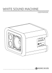
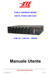
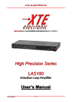
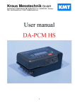
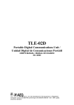
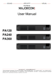
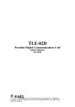
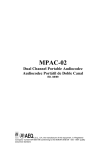
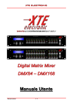
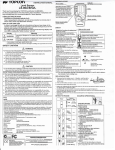
PAGING CONTROL
EMERGENCY
1
PLAY
MUSIC CONTROL
REMOTE
2
GAIN
TEL.
3
GAIN
4
GAIN
CD
5
GAIN
MUSIC ZONE SELECTOR
TAPE
6
GAIN
GAIN
LEVEL METER
Z1
+3
STOP
HIGH
HIGH
HIGH
HIGH
HIGH
HIGH
MIDDLE
MIDDLE
MIDDLE
MIDDLE
MIDDLE
MIDDLE
0
-7
LEVEL
BASS
ACTIVE
REC
3
4
5
6
7
8
2
1
MESSAGE
RECORDER
0
10
LEVEL
9
BASS
3
4
5
6
7
8
2
1
0
10
LEVEL
9
BASS
3
4
5
6
7
8
2
1
0
10
LEVEL
9
BASS
3
4
5
6
7
8
2
1
0
10
LEVEL
9
BASS
3
4
5
6
7
8
2
1
0
10
LEVEL
9
BASS
3
4
5
6
7
8
2
1
0
10
9
LEVEL
-15
Z2
COM 6X5
Z3
DIGITAL
PAGING PRE
ON
Z4
3
4
5
6
7
8
2
1
0
10
9
MASTER LEVEL
COM Series
COM 6X5
Digital Paging Pre
User’s Manual
Z5
I
ALL
POWER
Important safety instructions
This symbol indicates
the presence of
important directions for
use and information that
should be given
particular attention so as
to use the product
properly.
This symbol indicates
the presence of
“dangerous voltage” that
may cause the risk of
electrical shock. Pay the
utmost attention and
proceed cautiously.
1. Follow carefully the attached documentation
and keep it for future reference
2. Comply with the warnings
3. Store the packaging and check that all material
is in excellent conditions.
4. Do not use water near the product, do not pour
water or any other liquid on the amplifier. Do not to
use it with wet hands or feet into the water.
5. Do not use next to heat sources such as
radiators, stoves or the like.
6. Check the integrity of the mains cable. Do not
tread on the cable and do not squeeze the plug.
7. Connect the plug to a socket equipped with
grounding. Do not camper the plug. If the plug
supplied is not consistent with your socket, please
apply to an electrician for its replacement.
8. Connect to supply mains with the same voltage
as indicated on the back of the device.
9. Install the device in compliance with the
instructions.
10. Do not obstruct the air ducts.
11. Disconnect the appliance in case of storm and
if unused.
12. Connect according to the instructions only.
13. Do not connect an input signal higher than that
indicated in the manual.
14. Do not remove the upper or lower cover: there
is a risk of electrical shock.
15. Do not try to self-repair the appliance, but
apply to qualified personnel.
16. Clean with a dry cloth only.
17. The product shall be handled by skilled
personnel in the following cases:
-
mains cable or plug damaged
Exposure of the product to rain or humidity
Some liquid entered inside the unit.
An object fell on the unit
The unit fell down and is damaged
The product does not work correctly or shows
a remarkable change of performance.
21. A careful supervision is necessary if the
product is used in the presence of children or
inexpert adults.
22. This product could produce sound levels,
which cause damage to the hearing. Pay the
utmost attention and do not operate at high level
of volume or at an uncomfortable level for a long
time. Consult an audiometric specialist in case of
hearing loss or complaints.
Declaration of conformity
This device conforms to the requirements of the
EMC directive
89/336/EEC, amended by
92/31/EEC, and the requirements of the Low
Voltage Directive 73/23/EEC, amended by
93/68/EEC.
Standards Applied:
EN55103-1 (Emissions)
EN55103-2 (Immunity)
EN60065, Class I (Safety)
Radio interferences
A sample of this product has been tested and
approved to meet the requirements of the
Electromagnetic Compatibility Directive (EMC).
These requirements have been defined so as to
provide reasonable protection against dangerous
interference of electrical equipment. Whenever
this product has not been installed or handled
according to these guidelines, it might interfere
with other equipment such as radio receivers.
However, there is no guarantee that they should
not occur in a specific installation. Should this
equipment interfere with transceiver equipment
(such possibility can be checked by switching on
and off the device), the user should try to cancel
the interference by observing one or more of the
following measures:
-
-
Increase the distance between the device and
the receiver.
Connect the device to a plug linked to a
different circuit with respect to the one to
which the receiver is connected.
Redirect or move the receiver’s antenna.
Make sure that the unit concerned conforms
to the EMC immunity limits (CE-labelled). All
electrical equipment sold in the EC should be
approved as for what concerns protection
against electromagnetic fields, high tension
and radio interference.
Contact qualified personnel.
Introduction___
Congratulations on choosing XTE device and
thanks for trusting us and our products. Your
device has been carefully planned in the smallest
details, starting with every part of its equipment till
final assemblage. All products XTE are made with
the main purpose of guaranteeing our clients’ full
satisfaction, thus we underline that the product
you have chosen uses the most advanced
technology.
An improper use of the device can compromise its
correct operation. Therefore we recommend you
to carefully and correctly use it.
Read this manual carefully as it contains essential
information for a safe use of your device.
Unpacking______
Immediately inspect the package and its content
so as to check whether there are any signs of
damage. After unpacking check the product and
all parts, if you notice any damage inform your
dealer immediately.
It is advisable to save the packaging materials
even if the amplifier shows no sign of shipping
damage; you might have to return it to XTE or to
one of its dealers. Use the original package only,
which is the best way to protect the equipment
from shipping mishandling.
Installation/Assembly
Metal framing of all the XTE products is suitable to
be supported on a surface (table, etc.) and is
equipped with separated stirrups for assembly in
19” rack standard.
Dimension for mounting
Pay particular attention during the installation; we
remind you that the devices should not be installed
in places with:
•
•
•
•
•
•
High temperatures
Dust and excessive humidity
Presence of intense magnetic fields
Water next to the component
Vibrations
Closed spaces inhibiting a proper ventilation
Description____
The COM 6X5 mixer have been designed to
ensure durable performance and reliable
operation of sound system, in the most flexible
and professional way.
COM 6X5 is an advanced device that allows to
control 5 balanced audio outputs.
This product is complete of two kinds of inputs:
- 3 mixed MUSIC INPUT which are spread on the
selected zones by the MUSIC ZONE SELECTOR
push-button placed on the frontal panel
- 3 mixed PAGING INPUT which are priority on
the MUSIC INPUTS and characterized by different
priority level.
The main feature of this Mixer is the possibility to
select in remote position, only by the REMOTE
CONTROLLER RCX-5, on which of the 5 outputs
zone wants to talk, maintaining the background
music on the other not interested zones.
The Mixer is arranged for the connection of 3
RCX-5 that can become 6 thanks to the REMOTE
RECEIVER RRX-6 optional module.
The device is also arranged for the insertion of MR
30 optional card for digital voice messages
recording and playing.
The whole electronic circulation has quality and
safety features in working; it is provided with
“earth-lift” switch (on the back).
Features_______
COM 6X5 is equipped with a whole of features,
which help, in adapting mixer to particular
applications.
• CH1 MIC/LINE input electronically balanced,
usable for emergency paging microphone,
priority on all
• CH2 Remote Receiver input for the connection
of up to 6 RCX-5 Remote Paging Microphones
with priority activation order and zones
selection (Audio, data and power through one
cable UTP-Cat5), priority on CH3 and MUSIC
INPUT
• CH3 input for the connection to tel exchanger,
priority on MUSIC INPUT
• 3 MIC/LINE MUSIC INPUT electronically
balanced, adjustable for medium-high level
microphone and sources, connected to input
sockets for a simple use
• A 24 VCC potential is available at the MIC
sockets, for the eventual direct “phantom”
power supply
• Led power on indicator and Level meters
• Each channel is complete of Sensitivity
controls (GAIN), and Tones controls (TREBLE,
MIDDLE, BASS)
• Volume (LEVEL) separated to each input and
main volume control (MASTER)
• 5 balanced audio outputs 0dBu
• The unit is expected to work with 230 VCA –
50/60 Hz distribution systems and with 24 VCC
battery.
• The whole electronic circulation has quality and
safety features in working; it is provided with
“earth-lift” switch (on the back).
OPTINAL FEATURES
• C714 Din Don optional card with trimmer to
adjust the volume on the back panel
• RRX-6 Remote Receiver digital optional card to
extend the connection capacity up to 6 RCX-5
Remote Paging Microphones with priority
activation order and zones selection (Audio,
data and power through one cable UTP-Cat5)
• MR 30 optional card for digital voice messages
recording, 30sec Max. The card has Play,
Stop, Rec, volume (Level) control, Active led
and integrate microphone on the frontal panel.
The playing and repeat orders could be
activated by remote control connect to terminal
on the back. MR 30 module is priority on CH2,
CH3 and MUSIC INPUT.
Applications___
COM series is best suited for any applications, for
example: call and message transmission
installations with alert system, audio diffusion in
industrial enterprises, offices, hotels, schools,
supermarkets, restaurants, motorway restaurants,
auditoriums, gyms and similar.
Power Supply___
The unit is expected to work with 230 VCA – 50/60
Hz distribution system and with 24 VCC battery.
In case of power dysfunction, check the outside
and inside protection fuses (for 24 VCC) and
eventually replace them with others of same
calibration; if one of them burns out immediately,
do not go on and have check the unit by qualified
personnel.
Take away plug from 230 VCA electric power
socket and 24 VCC battery always, before
removing fuses and, in any case, open the unit
framing.
Installation___
Signal imput connection
Even though it has 6 input channels with a wide
versatility in using (adjusted sensitivity from
-51dBu to -6dBu), separated sockets are available
for a quick typological connection:
MUSIC INPUT
The audio sources connected to these imput are
mixed and sended to the output zones selected by
MUSIC ZONE SELECTOR phush buttons. (17 of
Fig.1)
Microphones
3 connectors of 3 female poles XLR type with
balanced audio input are used (34 of Fig.1).
A 24 VCC potential for direct “phantom” supply of
electret-type microphones could be joint to CH4
socket (on the same balanced phonic line),
through the multi-micro switch placed on the back
(37 of Fig.1); therefore, before connecting a
microphone it should pay attention to the model (if
dynamic or electret). In case of dynamic
microphone do not insert 24 VCC; insert it with
electret microphone only.
For the use of tuners and radio microphones,
audio from video projectors, outside audio lines (to
be protected by inserting a separator transformer),
message and tone generators, etc., both
microphones connectors (i.e. those remained
available) and those further on described.
CD
For the use of CD a couple of mono-female-RCA
connectors (unbalanced audio) is arranged.
Listening will be monophonic also using stereo
cables directly plugged in.
Using CD sockets (33 of Fig.1), it will be
impossible connecting anything to Microphone 5
socket, because Sensibility, Tones and Volume
adjustments for “CD” are made with “Micro 5
sector” of preamplifier.
TAPE INPUT – REC
For the use of tape Recorders or spools 2 couples
of mono-female-RCA connectors (unbalanced
audio) are arranged. Listening and recording will
be monophonic also using stereo cables directly
plugged in.
As already said, it is impossible to connect
anything to Microphone 6 socket by using RECTAPE sockets (31; 32 of Fig.1), because
Sensibility, Tones and Volume adjustments for
“Tape” are made with “Micro 6 sector” of
preamplifier.
INGRESSI PAGING
The audio sources connected to these imput are
mixed, with the priorità on the Music Input and
characterized by different priority level:
Microphones
2 connectors of 3 female poles XLR type with
balanced audio input are used (36 of Fig.1).
A 24 VCC potential for direct “phantom” supply of
electret-type microphones could be joint to CH4
socket (on the same balanced phonic line),
through the multi-micro switch placed on the back
(37 of Fig.1); therefore, before connecting a
microphone it should pay attention to the model (if
dynamic or electret). In case of dynamic
microphone do not insert 24 VCC; insert it with
electret microphone only.
In order to activate the priority of channel CH1 it is
necessary to close the contact Priority Control. (23
of Fig.1)
REMOTE RECEIVER INPUT LINK
Input with RJ45 Connector for power supply, data,
audio signal transmission up to 3 RCX-5. (26, 27
of Fig.1)
TEL INPUT
The CH3 is arranged for the login of audio signal
for voice calls through telephone exchanges.
Signal output connection
The device is arranged with 5 balanced audio
output zones 0dBu (22 of Fig.1).
For a good system working
•
•
•
•
•
Keep channel and master volume at about
80%. (12; 15 of Fig.1).
Adjust the GAIN (10 of Fig. 1) to have, in
normal working conditions, maximum output
signal level (level meter = 0dB, 14 of Fig.1).
Optimise intelligibility with channel equalizer.
(9,11,13 of Fig.1).
Reduce MASTER volume (15 of Fig. 1) in
order to obtain the required power.
Be sure that mass commutator (29 of Fig. 1)
is in mass-connected position.
Optinal Cards___
MR 30
Their insertion has to be made in an authorized
assistance centre or directly in factory.
C714
• C714 Din Don optional card with trimmer to
adjust the volume on the back panel (30 of
Fig.1).
The card generate the two tone DIN DON
signal when the PRIORITY CONTROL contact
turn close (23 of Fig.1), when a signal come
from the telephone exchanger connected to the
input CH3 or when someone push the TALK
push button on the Remote controller RCX-5.
MR 30 optional card is a micro-controlled
recording/playing module of one or two messages
designed to universal use.
The recording is made on a non-volatile memory,
which allows keeping the recording stored even
without power supply.
The module has been designed for playing
messages, tones and sirens.
In the case of evacuation or emergency paging,
either activated from the front or the remote
controls.
The internal microphone allows to use this product
without any other additional device, and is possible
to recording or changing the message anywhere
and anytime, even on the place of installation.
RRX-6
XTEelectronic
DECLINES
ANY
RESPONSIBlLITY ON THE CONSEQUENCES
OF AN ACCIDENTAL ACTIVATION OF AN
EMERGENCY PAGING.
RRX-3 Remote Receiver digital optional card for
the connection of up to 6 RCX-5 Remote Paging
Microphones with priority activation order and
zones selection (Audio, data and power through
one cable UTP-Cat5)
The card include:
1) SLAVE / PRIORITY – Switch to set CH2 and
the possible RCX-5 connect in SLAVE or
PRIORITY mode (24 of Fig.1).
See PRIORITY LEVELS table to understand
the functioning.
NOTE: The PRIORITY function is active only if
at least one of the RCX-5 connect is adjusted
in PRIORITY mode.
2) DATA – Led indicator of data receiving in
progress. (25 of Fig.1).
3) INPUT / LINK – RJ45 connector for the
transmission of main, data, audio signal to
RCX-5 (26, 27 of Fig.1).
1) MAIN FEATURES
•
Capacity for one message of 32 seconds.
•
Storage of the message without battery.
•
High quality sound thanks to its digital
recording system.
•
Internal microphone accessible from the
front panel.
•
Front
controls
of
message
recording/playing.
•
Front throbbing led indicator.
•
Rear connector for remote playing control.
•
Endless repetition of one message.
•
Internal compressor to avoid the
recording saturation.
•
Recording protection.
•
Adjustment potentiometer for the output
signal level.
2) RECORDING
The internal microphone (4 of Fig.1) allows the
recording without any other additional device or
microphone.
The procedure for recording a message is the
following:
1.
Set the micro switch on the back panel
(20 of Fig.1) in the no REC MESSAGE
PROTECT position.
2.
Press the REC push-button (6 of Fig.1)
to start the recording. The red Led will throb (5
of Fig.1), and it will keep throbbing during the
recording.
3.
Once the message has been recorded,
press the STOP push-button (2 of Fig.1),
unless the maximum recording time has been
finished (if, during the recording the led is off, it
means that the recording time is off). In such a
case, you must not press the STOP pushbutton.
Once the message has been recorded, it can
be protected by placing either the micro switch
on the back panel in the REC MESSAGE
PROTECT position (20 of Fig.1).
The message can be recorded again or
deleted as many times as required. You must
only unprotect the recording (if appropriate)
and repeat all the procedure.
3) PLAYNG
The Playing procedure can be done either
through the front or the rear controls.
The procedure for playing a message through
the front controls is the following:
1.
Press the PLAY push-button (1 of Fig.1)
as to start the playing. The red Led will throb (5
of Fig.1), and it will keep throbbing during the
playing.
2.
If you want to stop the playing, press the
STOP push-button (2 of Fig.1).
3.
You can adjust the output signal level by
the LEVEL control (3 of Fig.1).
The procedure for playing a message through
the rear controls is the following:
Close the normally open contact START
MESSAGE (19 of Fig.1) as to start the playing.
The red Led will throb (5 of Fig.1), and it will
keep throbbing during the playing.
If You wont continuously more repetition of the
message, keep closing the normally open
contact START MESSAGE (19 of Fig.1) for the
required times.
Advanced Function
VOX
CH3 input is arranged by “VOX” function for the
connection to tel. exchanger.
Thanks this function when one signal comes from
the tel. exchanger the channel priority become
automatically active and the telephonic signal
goes to the output zones.
DIN-DON function could be related with VOX by
micro-switch (35. of Fig1), which get active the
C714 DIN DON (OPTIONAL) card when the CH3
priority function becomes active.
Priority Function
The mixer is complete of an advanced “Priority”
system, which could be used to assign the Priority
to some inputs rather than some other inputs.
The Paging input are always priority on the Music
input.
C714 DIN-DON card could be mounted like
OPTIONAL and It get active by the priority
function.
In the following table are classified all the inputs in
according to the priority level, from 1 (highest
priority level) to 7 (lowest priority level).
Also are indicated the way to modify the device,
for change the priority level and the C714 DIN
DON optional card work mode, in according to the
input.
Music Zone Selector
The device is provided with an output terminal
board complete of 5 balanced output zones 0dBu
(22 of Fig.1).
The mixed signal from Music input could be
directed to one output zone only, to all or only
some.
The output zones could be selected on the mixer
by the switch on the frontal panel (17 of Fig.1).
The active output zones are indicated by Led (14
of Fig.1).
NOTE: If JP4 on the MR30 optional card is ON
(See Fig.2), the priority level become First on First
with the CH1 ones, the first activated exclude the
other.
When the priority is get activated, all the other
inputs with lower priority level softening
The “Priority” order could be active by different
way in according to the input:
• CH1 – To close the normally open contact
PRIORITY CONTROL (23 of Fig.1)
• CH2 / RRX-6 – By the TALK push button on
Remote Controller RCX-5.
• CH3 – When one signal comes from to the
CH3 input.
• MR30 – When the playing starts.
PRIORITY LEVEL
INPUT
CH1
MR30
RCX-5 - CH2
CH3 - VOX
CH4-5-6
1
2
3
X
X
JP4=on
4
5
6 7
X
NOTE
Din-Don is getting active.
Level 4 only in according to
RCX-5 when It is in priority
mode.
X
JP4=off
Din-Don is never getting
active. When JP4=on
become “first in first“ with
CH1
X
Priority Mode
X
Slave Mode
Din-Don is getting active.
X
Could be in according to
Din-Don=on
X
Specifications_
TAPE/CD input sensitivity
MICRO/LINE input sensitivity (CH3 TEL)
Balanced input impedance
Bass control
Middle control
Treble control
TAPE REC output level
BAL OUT Nominal level (Master =50%)
BAL OUT Max level (Master =100%)
Frequency response MIC (@-3 dB)
Frequency response LINE (@-4 dB)
Signal/noise ratio (weighted 20÷20KHz): micro
Signal/noise ratio ( weighted 20÷20KHz): aux
Power supply voltage from AC main
Power supply voltage from battery
Consumption
Dimensions (WxHxD)
Weight (Kg)
Remote Controller RCX-5
Remote Receiver CH2
-38 ÷ +9 dBu
-51 ÷ -6 dBu
10 Kohm
± 12 dB a 60 Hz
± 8 dB a 700 Hz
± 12 dB a 10 KHz
-8 dBu
+0 dBu
+6 dBu
80-16.000 Hz
30-20.000 Hz
>62 dB
>80 dB
230 V CA 50÷60 Hz
24 VCC
45VA
443(Rack482)x88x256
3
Connection up to 3 RCX-5,
LAN cable at the 100mt MAX
MR 30 – Recording capacity
1 message 0÷30sec. ,
Terminal for Fire system
Connection up to 3 RCX-5,
LAN cable at the 100mt MAX.
Remote Controller RCX-5
Remote Receiver RRX-6
21. BATT –24 VCC mains input for external battery
22. BAL OUT – 5 balanced output zones 0dBu
23. PRIORITY CONTROL – Contact for the priority
order activation
24. PRIORITY/SLAVE – Switch to set the signal come
from RCX-5 in PRIORITY or SLAVE mode
25. DATA – Data receiver in progress indicator
26. LINK – Output with RJ45 connector for the
connection with Remote Controller RCX-5, available
on CH2 channel.
27. INPUT – Input with RJ45 connector for the
connection with Remote Controller RCX-5, available
on CH2 channel.
28. MAINS – 230 V~ supply mains socket, with
protection fuse of CA mains.
29. GND LIFT – Micro-switch to connect electrical mass
to chassis
30. VOLUME DIN DON – DIN DON signal volume.
(With C714 optional card only)
31. REC – Stereo output for audio recorder
32. TAPE INPUT –Stereo input for audio recorder,
available on CH6 channel
33. CD INPUT–compact disc input, available on CH5
channel.
34. MICRO/LINE MUSIC INPUT from CH4 to CH6
Inputs in variable sensitivity configuration, arranged
for Microphone; when CD and TAPE are used just 4
channels are available for micro use.
35. DIN DON ON – Micro-switch to set the activation of
DIN DON signal in according with the priority of the
CH3
36. MICRO/LINE PAGING INPUT CH1, CH2 Inputs in
variable sensitivity configuration, arranged for
Microphone
37. PHANTOM – Micro-switch to connect the 24VCC
phantom main with the inputs from CH1, CH3 and
CH4.
Commands and Functions
(as per Fig.1)
1. PLAY – Voice message playing push button (With
MR30 optional card only)
2. STOP – Voice message STOP push button (With
MR30 optional card only)
3. LEVEL – Voice message signal output level
adjustment (With MR30 optional card only)
4. MICROPHONE – Internal microphone (With MR30
optional card only)
5. ACTIVE – Throbbing Led indicator of voice
message recording / playing (With MR30 optional
card only)
6. REC – Voice message REC push button (With
MR30 optional card only)
7. PAGING CONTROL – Control panel for Paging
channels
8. MUSIC CONTROL – Control panel for Music
channels
9. HIGH – High tone adjustment
10. GAIN – Gain adjustment
11. MIDDLE – Middle tone adjustment
12. LEVEL – MIC/LINE input volume
13. BASS – Bass tone adjustment
14. LEVEL METER – Audio level indicator
15. MASTER LEVEL – Main volume
16. MUSIC ZONE SELECTOR LED – Music signal
output zones selected indicator
17. MUSIC ZONE SELECTOR – Music signal output
zones selector
18. POWER – Power switch
19. START MESSAGE – Voice message remote
playing order connector (With MR30 optional card
only)
20. REC MESSAGE PROTECT – Micro-switch to
protect the voice message recording (With MR30
optional card only)
FIG 1
9
10
1
EMERGENCY
1
PLAY
14
16
MUSIC CONTROL
REMOTE
2
GAIN
TEL.
3
GAIN
4
GAIN
CD
5
GAIN
MUSIC ZONE SELECTOR
TAPE
6
GAIN
LEVEL METER
GAIN
Z1
+3
HIGH
STOP
HIGH
HIGH
HIGH
HIGH
HIGH
0
-7
MIDDLE
LEVEL
MIDDLE
BASS
ACTIVE
3
REC
4
5
3
7
8
1
0
10
LEVEL
MESSAGE
RECORDER
BASS
6
2
6
20
4
5
0
10
LEVEL
21
5
BASS
6
3
7
8
1
4
5
3
7
8
1
0
10
LEVEL
+ -
+ -
MAINS
230 V~ 50÷60Hz
Z5
+ Z4
5
2
1
9
3
7
8
0
10
LEVEL
4
5
3
7
8
1
0
10
LEVEL
+ Z3
Z2
4
5
6
7
8
2
1
9
0
10
Z5
ALL
9
POWER
MASTER LEVEL
15
23
+ -
DIGITAL
PAGING PRE
Z4
6
2
9
COM 6X5
Z3
ON
BASS
6
Z2
24
+ - - +
Z1
MUSIC
REC
TAPE INPUT
25
26 27
24
17
25
18
26 27
REMOTE RECEIVER - CH 2
PRIORITY DATA
LINK
INPUT
REMOTE RECEIVER - CH 2
PRIORITY DATA
LINK
INPUT
SLAVE
SLAVE
MICRO/LINE MUSIC INPUT
CD INPUT
+
FOR CONTINUED
GROUNDING
PROTECTION DO NOT
REMOVE SCREW
XLR BAL INPUT
29
CH 3
TEL INPUT
RISK OF ELECTRIC SHOCK
DO NOT OPEN
WARNING:TO REDUCE THE RISK OF
FIRE OR ELECTRIC SHOCK DO NOT EXPOSE
THIS EQUIPMENT TO RAIN OR MOISTURE.
TO PREVENT THE RISK OF FIRE HAZARD
REPLACE WITH SAME TYPE 230 VOLT FUSE.
G
BALANCED MICRO/LINE PAGING INPUT
CAUTION
S.N.
GND LIFT
A/250V~
4
-15
13
22
24V
BATT
MIDDLE
BASS
6
2
9
0
10
LEVEL
MIDDLE
BAL OUT
REC
MESSAGE
PROTECT
28
4
2
9
12
START MESSAGE
FUSE T
3
7
8
1
MIDDLE
BASS
6
2
9
11
19
MIDDLE
PRIORITY
CONTORL
3
5
8
PAGING CONTROL
2
4
7
VOLUME
DIN DON
CH 6
CH 5
30 31 32 33
CH 6
CH 5
34
34
CH 4
DIN DON
ON
CHANNEL
1
4 3
CH 3
34 35 36
1 = GND
2 = HOT +
3 = COLD -
PHANTOM
24V
CH 1
37
36
FIG.2
MR 30 INTERNAL MODIFY
JP4 OFF - PRIORITY LEVEL 2
JP4 ON - PRIORITY LEVEL
"First in First" CH1
FIG.3
+
G
+ -
24V
BATT
+ Z5
+ Z4
+ -
+ -
Z3
Z2
OPTIONAL
START MESSAGE
REC
MESSAGE
PROTECT
+ - - +
Z1
PRIORITY
CONTORL
BAL OUT
System Architecture Diagram
PA360 AMPLIFIER Z1
PA360 AMPLIFIER Z2
RCX- 5
RCX- 5
RCX- 5
RCX- 5
PA360 AMPLIFIER Z3
PA240 AMPLIFIER Z4
PA240 AMPLIFIER Z5
RCX- 5
RCX- 5
24VDC
FIRE SYSTEM
TEL
EXCHANGER
RECORDER
EMERGENCY
MICROPHONE
PAGING
MICROPHONE
CASSETTE DECK
MICROPHONE
CD PLAYER
MICROPHONE
MUSIC INPUT
PAGING INPUT
LINE SIGNAL
XXTTEE eelleeccttrroonniicc
Via Tragni, 6
42043 Gattatico RE
ITALY
Tel. +39 0522 900166
Fax. +39 0522 678548
EN_COM6X5 / Rev. 1.0
!
!