1
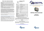
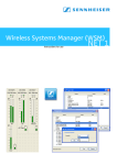
Works with:
MI CASA VERDE VERA
NEVO
AEON LABS
mControl
ADT Pulse
Z-Wave AC Motor Shutter
Controller
DHS-ZW-TMC-01
User Guide
Z-Wave Technology for Automated Homes
Z-Wave is a state of-the-art wireless technology used as a standard for wireless home control. It is a next-generation
wireless ecosystem that lets all your home lighting systems and electronics talk to each other, and to you, via a
controller or a gateway. It uses simple, reliable, low-power radio waves that easily travel through walls, floors and
cabinets. All products in Australian / New Zealand version (921.4h MHz) featuring the Z-Wave logo are certified to
work smoothly with each other.
Product Overview
The DHS Z-Wave AC Motor Shutter Controller DHS-ZW-TMC-01 is Z-Wave Shutter device specifically designed for
use in smart homes and offices.
The product allows to operate roller blinds/shutters wirelessly using a Z-wave enabled (AUS/NZ version 921.42
MHz) controllers (compatible universal remote controllers, control panels, gateways, PC with Z-Wave USB dongle)
or manually via connected manual switch.
The shutter controller can act as a wireless repeater to ensure that commands intended for another device in the
network are received. This is useful to eliminate “RF deadspots” when the radio range of the Z-Wave network is influenced. This function is part of the Z-Wave network functionality and is set up via Z-Wave controller.
Wiring diagram
Installation
1. Turn power OFF by switching off the Main circuit breaker and test that power is OFF before wiring!
2. Ensure Shutter Controller capacity matches the load requirements.
3. Wall Installation: Connect it with your external switch, default is two buttons with neutral
position switch. Please see Wiring Diagrams & Configuration Parameters. You can use 2 Gang Clipsal
Wall Plate with two push buttons.
4. Re-apply power to the Main circuit breaker to test the system carefully, if the indicator light on
Shutter Controller blinks 30 seconds and then keep breathing, it means the installation is done in
right way.
5. Turn OFF the power again.
6. Shutter Controller is in wall device. Please secure it behind wall plate with push buttons. Please be
careful not to pinch or crush wires. Reapply power to the circuit at Main circuit breaker.
Manual Operations
Press and release the buttons on the connected push buttons to turn UP / DOWN the connected motor.
It is recommended that you wire your Shutter Controller and include it into Z-Wave network before mounting it in a wall cavity. Leigh of wires between manual button and device must be less than 0.5m.
Please note:
in Australia and New Zealand the installation must be done by certified electrician.
Please note. Buttons on the wall plate have to be Bell Press type (e.g. push-button Saturn
Series 60PBBP or similar).
Please note:
Please check the maximum load before installing or operating.
Please note: 6A external fuse before the Shutter Controller must be installed in line to
protect against overload.
Maximum load: 250V ~ a.c. 50Hz , 1.8HP
Z-Wave Operations
Before including the product to your Z-wave network it is advised to perform removal procedure to reset
network settings.
The Z-Wave Shutter Controller must be included into your Z-Wave home network before it can send and receive ZWave commands. The Z-Wave Shutter Controller can only communicate to devices within the same Z-wave home
network.
Always follow your controller’s specific instructions for Z-Wave inclusion, exclusion, association and control operations.
Exclusion from Z-wave home network – general instructions
1. Install Connect the Z-Wave Shutter Controller to the load, power circuits and to the manual switch as per instructions in the section INSTALLATION above.
2. Start exclusion procedure on your controller and when requested 3 times quickly press and release a button
on the connected manual Press Button switch. During the whole procedure the controller and Z-Wave Shutter
Controller must be close proximity of not more then 15cm.
3. Successful exclusion will be indicated by your Z-Wave remote controller. LED on the
Z-Wave Shutter Controller will start slow blinking. In case exclusion was not successful, try the procedure again.
Inclusion to Z-wave home network – general instructions
1. Connect the Z-Wave Shutter Controller to the motor, power circuits and to the manual
switches as per instructions in the section INSTALLATION above.
2. Make sure your Z-Wave Gateway is in the correct operating mode (inclusion). To include quickly press and
release 3 times a button on the connected manual Press Button switch.
During the whole procedure controller (Gateway) and Z-Wave Shutter Controller must be in close proximity of
15cm. Successful inclusion will be indicated by your Z-Wave remote controller (Gateway). In case inclusion was not
successful, try the procedure again or reset network settings by running exclusion procedure (see below).
3. Once the Z-Wave Shutter Controller has been added into your Z-Wave home network
successfully, you may need to assign it to a specific button on your controller (Gateway).
Refer to your Z-Wave controller (Gateway) / panel for instructions on how to do this.
4. Now, you can control your lamp via your Z-Wave Gateway or other controller.
Indication modes
The indicator gives various statuses of the device as follows:
1. Automatically add: blinks 30 seconds.
2. Ready for learn mode: Indicator light Breathing.
3. Learn in progress (add): Indicator light blinks 1 time.
4. Learn in progress (remove): Indicator light blinks 1 second (8 times).
5. Learn mode success: Indicator light is on for 1 time. (and then if load is on, indicator light keep on; if load
is off, indicator light keep breathing)
6. Learn mode failed: Indicator light blinks fast.
Technical Specifications
RF Protocol:
Z-Wave (MultiChanel Command Class)
Connections type:
See wiring above
Manual Switch compatibility: Bell Press type buttons or two buttons with neutral position switch
Operating Voltage:
AC 240V / 50Hz
MaxLoading:
6A, 1.8 HP ~240V AC motor
Switch type:
Universal (relay)
RF Frequency:
921.42Mhz - AU/NZ approved RF for Z-Wave
Operation Range:
Up to 30m when no obstacles
Application:
Indoor use only
Operation temperature:
0 ~ 55 °C
Storage temperature: 10 ~ 80 °C
Weight:
70g
Housing:
ABS
Dimensions
LxWxH: 48mm x 45mm x 18 mm
Compliance:
AS/NZS 4268:2008, AS/NZS CISPR 14.1, IEC60669-2-1
RCM:
N5496
Supporting Z-Wave Command Classes
Basic Class: Slave with routing capabilities
Generic Class: Multilevel Switch
Specific Class: Motor Control Class C
class:0x27 COMMAND_CLASS_All_Switch
class:0x8E COMMAND_CLASS_Multi_Channel_Association
class:0x70 COMMAND_CLASS_Configuration
class:0x72 COMMAND_CLASS_Manufacturer_Specific
class:0x75 COMMAND_CLASS_Protection
class:0x77 COMMAND_CLASS_Node_Naming_and_Location
class:0x86 COMMAND_CLASS_Version
class:0x25 COMMAND_CLASS_Binary_Switch
class:0x20 COMMAND_CLASS_Basic
class:0x26 COMMAND_CLASS_Multilevel_Switch
class:0x87 COMMAND_CLASS_Indicator
class:0x85 COMMAND_CLASS_Association
class:0x2B COMMAND_CLASS_Scene_Activation
class:0x2C COMMAND_CLASS_Scene_Actuator_Configuration
Configuration Parameters
Parameter No. 1,
Size 1,
Default 3
Name: Buttons mode
Description: One push button: One button is used (chose any), press while moving up and down stops, while
stopped moves to opposite direction to previous. // Two buttons with neutral position: Up click moves up if
stopped and stops if moving down, Down click moves down if stopped and stops if moving up, Hold Up/Down
moves in up/down, Release stops. // Two toggle switch: Switch to Up/Down moves up/down. // Two paddles
with Power and Direction: Hold Up button to move blinds up. If Down button is pressed, blinds will move down.
Release Up button to stop.
Type: rangemapped
Values:
0 -> One push button
1 -> Two paddles with Power and Direction
2 -> Two toggle switch
3 -> Two buttons with neutral position
Parameter No. 2,
Size 2,
Default 0
Name: Automatically close after
Description: If not zero, automatically close blind after a user defined time
Type: range
Values:
0 -> Disabled
1 - -1 -> sec
Parameter No. 3,
Size 1,
Default 0
Name: What to do on RF close command
Description: Defines how to interpret RF Off command. Can be used in conjunction with Auto Close function:
Ignore - to open the door by motion detectors and close it back after some amount of time: in case of multiple
motion detectors each would try to open that would break logics; Open - to open on both On and Off paddle
press on the remote and close after some amount of time. Button close click will still work (if button operations are
not disabled). Note that Dim Down command will still begin close motion.
Type: rangemapped
Values:
0 -> Close
1 -> Ignore
2 -> Open
3 -> Open if closed, otherwise Close
Parameter No. 4,
Size 1,
Default 50
Name: Typical click timeout
Description: Typical time used to differentiate click, hold, double and triple clicks
Type: range
Values:
1 - 100 -> in 10ms units
Parameter No. 5,
Size 1,
Name: Invert buttons
Description:
Type: rangemapped
Values:
0 -> No
1 -> Yes
Default 0
Parameter No. 6,
Size 1,
Default 1
Name: Action on button press or hold
Description: Defines which command should be sent to Association group on button press or hold. Scene mode
will send 1 for Up event, 2 for Stop, 3 for Down.
Type: rangemapped
Values:
1 -> Switch On, Off and dim using Basic Set and MultiLevel Start/Stop Changing
2 -> Send Scene
Parameter No. 7,
Size 1,
Default 1
Name: LED mode
Description: Set LED indication mode
Type: rangemapped
Values:
0 -> Disabled
1 -> Show working state
2 -> Always on
3 -> Show opened state
4 -> Indicator Command Class
Parameter No. 10,
Size 1,
Default 60
Name: Full close time
Description: Time to go from opened to closed state. Used to estimate the current level. Note that in Permanent
motion mode the reported value would be Closed or Opened, while all Basic and Multilevel Set values (1-99, 255)
would Open except 0 value that would Close.
Type: range
Values:
0 -> Keep in permanent motion
1 - -1 -> seconds
Parameter No. 11,
Size 1,
Default 60
Name: Full open time
Description: Time to go from closed to open state. This value may differ from full close time for some blinds due
to gravity. Used to estimate the current level. Note that in Permanent motion mode the reported value would
be Closed or Opened, while all Basic and Multilevel Set values (1-99, 255) would Open except 0 value that would
Close.
Type: range
Values:
0 -> Keep in permanent motion, 1 - -1 -> seconds
Parameter No. 11,
Size 1,
Default 60
Name: Full open time
Description: Time to go from closed to open state. This value may differ from full close time for some blinds
due to gravity. Used to estimate the current level. Note that in Permanent motion mode the reported value
would be Closed or Opened, while all Basic and Multilevel Set values (1-99, 255) would Open except 0 value
that would Close.
Type: range
Values:
0 -> Keep in permanent motion
1 - -1 -> seconds
Parameter No. 12,
Size 1,
Default 0
Name: Node Id of the blocking device
Description: Id of the device which commands would be interpreted not as Open/Close, but as block/unblock.
Useful with door opening detector: if the door is open, block the blind not to break shades while they move.
Type: range
Values:
0 -> Disabled
1 - -24 -> Node Id
Parameter No. 13,
Size 1,
Default 0
Name: On which command from blocking node to enable the protection
Description: Defines which command from blocking device to interpret as closed door and hence, unprotected.
Type: rangemapped
Values:
0 -> on On
1 -> on Off
Parameter No. 14,
Size 1,
Default 0
Name: Invert open and close relays
Description: Allow exchanging open and close relays if blind control is wired to the motor incorrectly
Type: rangemapped
Values:
0 -> No
1 -> Yes
Association Groups
Group Number Max Nodes Description
1 10 Click, press and hold of up/down buttons
2 10 Send Reports on blind state change
Configuration Reset
The Shutter Controller supports a configuration resets function.
Configuration reset means ‘All’ configuration values are defaulted.
This function can be activated by sending a configuration set frame.
SAFETY INSTRUCTIONS
Always read the safety instructions carefully:
- Keep this User’s Manual for future reference
- Keep this equipment away from high humidity and any liquid.
- This product is for indoor use only inside dry wall cavity or similar environment. Keep e
nough space around for ventilation.
- Do not connect to the load bigger then maximum approved for this product
- Do not connect to the non-compatible load
- If the product’s enclosure, is damaged, it shall be replaced by the manufacturer or its ser
vice agent or similarly qualified person in order to avoid a hazard
- DO NOT INSTALL THIS DEVICE INSIDE SEALED INCLOSURES AND METAL BOXES. ALWAYS
LEAVE ROOM FOR VENTILATION.
- INSTALLATION MUST BE DONE BY CERTIFIED ELECTRICIAN.
Specifications are subject to change without further notice
The information in this document is subject to change without notice. Digital Home Systems Pty Ltd (DHS) does not make any representations or warranties (implied or otherwise) regarding the accuracy and
completeness
of this document and shall in no event be liable for any loss of profit or any commercial damage, including but not limited to special, incidental, consequential, or other damage.
TRADEMARKS
All trademarks and registered trademarks are the property of their respective owners or companies.
DHS One (1) Year Limited Warranty
Digital Home Systems Pty Ltd warrants this DHS branded hardware product against defects in materials and workmanship under normal use for period of one (1) year from the date of retails purchase by the
original enduser
purchaser (‘Warranty Period’). PLEASE NOTE: breaking security label will void the warranty.
Terms and conditions
To see complete terms and conditions browse to http://www.digitalhomesystems.com.au/images/stories/DHS_Terms_and_conditions.pdf
Product of Digital Home Systems Pty Ltd
See all range of compatible devices at www.digitalhomesystems.com.au
Enquiries Sales and Marketing Email: [email protected]
© 2012 Digital Home Systems Pty Ltd. All rights reserved.