1
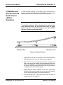
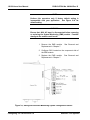
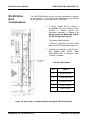
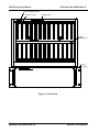
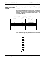
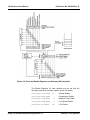
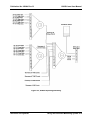
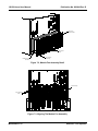
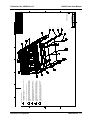
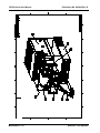
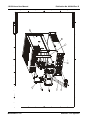
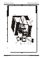
Publication No. 980844 Rev. B
Removal and
Replacement of
The Module Fan
Assembly
Astronics Test Systems
1261B-Linear User Manual
The plug-in module fan assembly may be removed and replaced
as described in the following steps. Refer to Figure 7-3 and 7-4.
1.
On rackmount (9U) mainframes only, loosen fan cover
thumbscrews, lower cover and disengage from housing.
Remove two phillips head screws per side and two
socket-head cap (Allen) screws and lockwashers inside
rear of cabletray. Pull bottom of housing away and
downwards disengaging retaining hooks from rear of
module fan assembly. This will expose the fan assembly
for removal.
Omit this step for benchtop (7U)
mainframes.
2.
Loosen the lower center captive thumbscrew on the fan
filter frame. Lift it up and towards the rear to remove the
frame and filter from the rear of the module fan
assembly.
3.
Loosen the four captive thumbscrews which secure the
module fan assembly to the mainframe.
4.
Ensure that all four thumbscrews are disengaged from
the mainframe. Grasp the module fan assembly by the
bottom right and top left floating thumbscrew.
5.
Remove the module fan assembly by pulling gently
toward the rear of the mainframe while gripping the
assembly by the two thumbscrews.
6.
To reinstall the module fan assembly, first align the
assembly with the rear of the mainframe.
7.
Insert the fan assembly by gently pushing it forward into
the mainframe making sure the electrical connector is
properly mated.
8.
Tighten the four thumbscrews securing the module fan
assembly.
9.
Place filter in the filter frame and align the hooks on the
back of the filter frame with the slots on the module fan
assembly. Insert the frame and push down to engage.
10.
Tighten the captive thumbscrew to secure the fan filter
frame.
11.
On rackmount mainframe only, engage the hooks on rear
of fan cover assembly with the slots in the rear of the fan
assembly. Push up to seat and secure with hardware
removed in Step 1.
Maintenance 7-5