1
Publication No. 980844 Rev. B
Programming The
Trigger Subsystem
1261B-Linear User Manual
The 1261B provides the following trigger capabilities:
1)
Route a signal from the TRIG IN front panel input
connector to one of the TTLTRG lines on the VXI
backplane;
2)
Route a signal from one of the TTLTRG lines on the VXI
backplane to the TRIG OUT front panel output connecter;
3)
Apply a programmable delay between either the TRIG IN
signal and the TTLTRGx line or the TTLTRGx signal and
the TRIG OUT line.
4)
Route the TRIG IN front panel input signal directly to the
TRIG OUT front panel output (with or without a delay).
Note that by routing the TRIG IN input to the same TTLTRGx
line that is connected to the TRIG OUT output, the TRIG IN
signal may be connected to the TRIG OUT connector in addition
to the TTLTRGx line.
Connecting The
TRIG IN Input To a
TTLTRIG Line
The TRIG IN input may be connected to one of the TTLTRGx
lines (TTLTRG0 through TTLTRG7) . The following commands
may be used to connect the TRIG IN input to one of the TTLTRG
lines, or to disconnect the input from all of the TTLTRG lines:
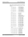
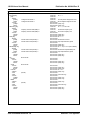
VXI:CONF:MONITOR:TRIG:INPUT
VXI:CONF:MONITOR:TRIG:INPUT
VXI:CONF:MONITOR:TRIG:INPUT
VXI:CONF:MONITOR:TRIG:INPUT
VXI:CONF:MONITOR:TRIG:INPUT
VXI:CONF:MONITOR:TRIG:INPUT
VXI:CONF:MONITOR:TRIG:INPUT
VXI:CONF:MONITOR:TRIG:INPUT
VXI:CONF:MONITOR:TRIG:INPUT
TTLTRG0
TTLTRG1
TTLTRG2
TTLTRG3
TTLTRG4
TTLTRG5
TTLTRG6
TTLTRG7
NONE
The first eight commands above connect the TRIG IN input to
TTLTRG0 through TTLTRG7 respectively. The last command
disconnects the TRIG IN input from all of the TTLTRG lines.
Note that by selecting one TTLTRG line, all other TTLTRG lines
are implicitly disconnected.
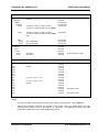
To determine which line is presently connected, the query:
VXI:CONF:MONITOR:TRIG:INPUT?
may be used. The reply to this query will be one of the following:
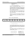
TTLT0
Astronics Test Systems
Using The Enhanced Monitoring System 4-23