1
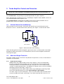
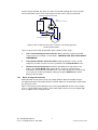
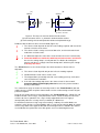
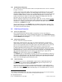
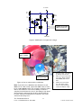
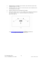
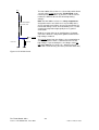
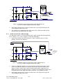
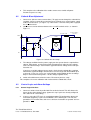
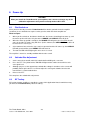
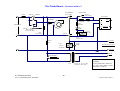
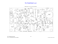
3.5 TX/RX Switching TX/RX changeover of the Triode Board is controlled via the PTT line, which switches the bias relay K1. You will also need to control the coaxial changeover relays – probably one at the input of the amplifier as well as one at the output. You will also need to control the coaxial changeover relays – probably one at the input of the amplifier as well as one at the output. Spare changeover contacts on K1 can be wired as you need – these are marked NC (closed on RX), NO (open on RX) and C (common). At this time the Triode Board does not provide sequenced TX/RX changeover on-board, but it is compatible with external sequencers. Many transceivers provide a few milliseconds delay between PTT operation and the start of RF output, which may allow you to switch the coax relays safely from the spare contacts of K1. The Triode Board will support full break-in changeover (QSK) if you replace K1 with an electronic bias switch and provide the necessary sequenced timing. 3.6 24V Relay Option The Triode Board includes its own rectifier and voltage regulator for the +12V DC rail. If you are using 12V DC relays, use the Triode Board as supplied, with a transformer input of 15V AC to the two AC IN terminals. If you are using 24V DC relays, you will need to make the following simple changes: 1. Change the transformer to 20V AC. 2. Change R28 to 10K. 3. Change R27 to a 15V 0.25-0.5W zener (e.g. BZX79-C15 or 1N4109 etc.) with its cathode stripe nearest to Q4. 4. Change R30 and R32 to 1K 1-2W. 5. Change K1 to RTE24024 (Schrack or Potter & Brumfield – see Parts List). 6. Underneath the board, cut the track marked 12V where it narrows, and link across the gap marked 24V as shown below. Figure 6: Modifications for 24V relays (underside view) 7. 3.7 The 12V regulator U6 will not need a heatsink. PTT Options When the PTT line is grounded, the current drawn from the transceiver is about 10µA. When the PTT line is un-grounded, the open-circuit voltage is regulated at +12V. This is compatible with the PTT output of almost every known transceiver. For transceivers that provide +12V output on transmit and a short to ground on receive, follow these conversion instructions: 1. On the underside of the board beneath U4, cut the thinned track between pin 4 and pin 11 (Figure 7). The Triode Board: AN-2 Issue 1.7 for board v2.4, June 2011 12 1999-2011 IFWtech Limited