1
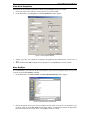
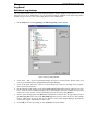
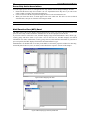
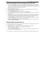
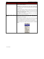
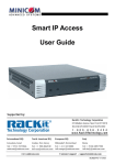
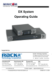
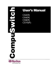
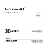
User Manual
Paragon Manager
PMG-0A-E
255-30-6100
Raritan Computer Inc.
400 Cottontail Lane
Somerset, NJ 08873
USA
Tel. 1-732-764-8886
Fax. 1-732-764-8887
E-mail: [email protected]
http://www.raritan.com/
Raritan Computer Europe, B.V.
Eglantierbaan 16
2908 LV Capelle aan den IJssel
The Netherlands
Tel. 31-10-284-4040
Fax. 31-10-284-4049
E-mail: [email protected]
http://www.raritan.com/
Raritan Computer Japan, Inc.
Kuga Building 7F
11-6, Kuramae 4-chome
Taitoo-ku, Tokyo 111-0051
Japan
Tel. 81-3-5833-6360
Fax. 81-3-5833-6336
E-mail: [email protected]
http://www.raritan.co.jp
Raritan Computer Taiwan, Inc.
5F, 121, Lane 235,
Pao-Chiao Rd., Hsin Tien
Taipei Hsien
Taiwan, ROC
Tel. 886-2-8919-1333
Fax. 886-2-8919-1338
E-mail: [email protected]
http://www.raritan.com.tw
Raritan Computer France
120 Rue Jean Jaures
93200 Levallois-Perret
France
Tel. 33-14-756-2039
Fax. 33-14-756-2061
E-mail: [email protected]
http://www.raritan.fr
Raritan Computer Deutschland GmbH
Lichstraße 2
D-45127 Essen
Germany
Tel. 49-201-747-9820
Fax. 49-201-747-9850
E-mail: [email protected]
http://www.raritan.de
Raritan Computer U.K. Ltd.
Unit 1 Cobbett Park, Moorfield Road
Guilford, Surrey, GU1 RU
United Kingdom
Tel. 44-1483-457788
Fax. 44-1483-46987
E-mail: [email protected]
http://www.raritan.com
Shanghai Representative Office of
Raritan Computer, Inc.
RM 19C-1 Shanghai Shiye Building
18 Caoxi North Road
Shanghai China 2000030
Tel. 86-21-64680475
Fax. 86-21-64627964
E-mail: [email protected]
http://www.raritan.com.tw/
March 2004
Copyright © 2004 Raritan Computer, Inc.
Supported by:
®
Technology Corporation
Rackit ® Technology Corporation
274 Madison Avenue, New York, NY 10016
Tel: (212) 679-0050 • Fax: (212) 679-0040
1 . 8 0 0 . 6 3 6 . 3 4 3 4
www.RackitTechnology.com
This page intentionally left blank.
Trademark Information
Product names mentioned in this document are trademarks or registered trademarks of their respective
companies. Paragon, and its logo is a registered trademark of Raritan Computer, Inc. Windows is a
registered trademark or trademark of Microsoft Corporation in the United States and other countries. Sun is
a registered trademark of Sun Microsystems. All other marks are the property of their respective owners.
System Requirements
Your system must meet these minimum requirements in order to run Paragon Manager:
Memory: 256MB
CPU: 750 MHz Pentium III processor
Minimum available disk space: 50 MB
For assistance in the U.S., please contact the Raritan Technical Support Team
at (732) 764-8886 or e-mail us at [email protected]
Ask for Technical Support – Monday through Friday, 8:00am to 8:00pm, EST.
For assistance internationally, please contact your regional Raritan office.
This page intentionally left blank.
Table of Contents
Chapter 1: Introduction .................................................................. 1
Paragon Manager Overview ......................................................................................................1
Log On .......................................................................................................................................1
Chapter 2: Operation ...................................................................... 3
Customize the Paragon Manager Window ................................................................................3
Paragon Manager Toolbar.................................................................................................................4
Device Panel ..............................................................................................................................5
Device View .......................................................................................................................................5
View By Channel ...............................................................................................................................5
View by Type .....................................................................................................................................5
User Panel .................................................................................................................................6
Create a User ....................................................................................................................................6
Delete a User.....................................................................................................................................7
View User Properties .........................................................................................................................8
Save Profiles .....................................................................................................................................8
Load Profiles......................................................................................................................................9
Log Panel .................................................................................................................................10
Edit Event Log Settings ...................................................................................................................10
Power Strip Window.................................................................................................................11
Edit a Power Strip ............................................................................................................................11
Power Strip Outlet Associations ......................................................................................................12
Multi Function View (MFV) Panel.....................................................................................................12
System Setup ..................................................................................................................................13
Paragon Manager Help ............................................................................................................14
Disconnect and Exit Paragon Manager ...................................................................................14
Chapter 3: Updating Paragon II Firmware ................................... 15
Update Paragon Matrix Switch(es) Using a TCP/IP Network ..................................................15
Update Paragon Matrix Switch(es) Using a Serial Connection ...............................................16
Firmware Update Interrupt Recovery.......................................................................................16
Appendix A: FAQs ......................................................................... 17
Table of Figures
Figure 1 Paragon Manager Login Window.......................................................................................................1
Figure 2 UMT Profile Window ..........................................................................................................................1
Figure 3 Paragon Manager Window ................................................................................................................2
Figure 4 Paragon Manager Window ................................................................................................................3
Figure 5 View Menu (check marks indicates panels in view) ...........................................................................3
Figure 6 Device Tree - View by Channel .........................................................................................................5
Figure 7 Device Tree - View by Type...............................................................................................................5
Figure 8 User Panel .........................................................................................................................................6
Figure 9 Add User Window ..............................................................................................................................6
Figure 10 Change Password Window ..............................................................................................................6
Figure 11 User Information Window.................................................................................................................8
Figure 12 Select Destination Path Window ......................................................................................................8
Figure 13 Confirm Load User Profile Window ..................................................................................................9
Figure 14 Edit Log Settings Window ..............................................................................................................10
Figure 15 Power Strip View Window.............................................................................................................11
Figure 16 Outlet Information Window.............................................................................................................11
Figure 17 MFV Displaying User Data.............................................................................................................12
Figure 18 MFV Displaying Power Strip Outlet Data .......................................................................................12
Figure 19 System Setting Window .................................................................................................................13
Figure 20Paragon Update Window ................................................................................................................15
CHAPTER 1: INTRODUCTION
1
Chapter 1: Introduction
Paragon Manager Overview
Thank you for choosing one of Raritan's Paragon series products! Your Paragon UMT appliance includes
Paragon Manager, a management and configuration application that lets you display Device, User, Log,
and Outlet information in one coordinated graphical user interface. You can Add, Modify, and Delete
Devices, Users, or Groups in your Paragon system from one central location, and specify log events to
keep an audit trail of events that are updated in real time. Complete administration of your Paragon
configuration is possible from a different room or from across the country using Paragon Manager.
Log On
Please note that only Administrators have permissions to log on to Paragon Manager.
1. On the Start menu, click Programs, and then click Paragon Manager. Click Paragon Manager
once more to launch the Paragon Manager application.
2. When the Paragon Manager window appears, on the Session menu, click Connect.
Figure 1 Paragon Manager Login Window
3.
4.
5.
Type your user name in the User Name field.
Type your password in the Password field.
Click on the Select UMT drop-down arrow and select one of the UMT devices from the list.
a. If the device to which you want to connect is not listed, click the […] button to add (or delete) a
UMT device. The UMT Profile window appears.
Figure 2 UMT Profile Window
2
PARAGON MANAGER USER MANUAL
b.
c.
d.
6.
Click [New] to add a new UMT device.
Type the name of the device in the UMT field.
Select the TCP/IP option button if you are using Paragon Manager with a UMT unit that has a
network admin (RJ45) port. All Paragon II and later UMT models have this port, and must be IP
addressed.
• Type the IP address of the UMT unit with which to communicate in the IP Address field.
• Type the Port number of the UMT unit with which to communicate in the Port field
• Type the appropriate encryption key of the UMT unit with which to communicate in the
Encryption Key field, if applicable.
e. Select the Serial option button if you are using Paragon Manager with a UMT unit that has a serial
admin (DB9) port.
• Click on the Port drop-down arrow and select the port from the list.
f. Click [Save] to save this new device and then click [Close] to return to the login window.
g. To delete a UMT unit from the list at any time, click the drop-down arrow in the UMT field and
select the device you wish to delete. Click [Delete] to delete the device, and then click [Close] to
return to the login window.
Click [Login] to log in to the UMT device through Paragon Manager. The Communication Progress
window displays your connection status; please note that it can take up to 30 seconds to connect. When
connected, the Paragon Manager window appears.
Figure 3 Paragon Manager Window
CHAPTER 2: OPERATION
3
Chapter 2: Operation
Customize the Paragon Manager Window
The Paragon Manager window contains the Paragon Manager menu bar and tool bar, the Device panel,
User panel, Log panel, and Power Strip View window. You can customize your view by resizing panels or
by viewing or hiding any of these components (except for the Device panel).
The Device panel displays all connected devices in your Paragon system, and the User panel displays all
users in your Paragon system. The Log panel displays the current activity of Paragon Manager. The Power
Strip View panel displays any power strips connected in your Paragon configuration.
When you connect to your Paragon unit via Paragon Manager, Paragon Manager downloads the Paragon
unit’s database and populates the Device, User, and Power Strip panels. All data from the Paragon is visible
in the Paragon Manager window. Once a session is initiated, updates to the database happen in real time
and changes to the Paragon database from other users are immediately reflected in your Paragon Manager
screen.
Device Panel displays all
connected
devices in the
Paragon II
system
Multi-Function
View (MFV)
Panel – displays
device and/or user
information
Power Strip View
Window –
displays power
strips and
connected ports
Device View
Tabs – view all
devices by
Channel or by
Type
User Panel –
displays users
and groups in
the system
Log Panel –
displays tracked
events by date
and time
Figure 4 Paragon Manager Window
Display or hide any of these panels, except for the Device panel, by selecting options on the View menu;
click on the desired panels in the menu to view or to hide them. A check mark before the menu item
indicates that it is in view. By default, the Device panel cannot be hidden.
Figure 5 View Menu (check marks indicates panels in view)
Resize the window panels by resting your mouse cursor on the border of two panels until a double-headed
arrow appears. Click and drag the arrow to size the panel up/down or left/right.
4
PARAGON MANAGER USER MANUAL
Paragon Manager Toolbar
The Paragon Manager toolbar displays several most commonly used commands as shortcut buttons in order
to save you time.
BUTTON
COMMAND
Connect: Launches the login dialog for Paragon Manager
Disconnect: Disconnects the Paragon Manager session
Add User: Adds a new user account in Paragon Manager and the connected Paragon
system
Delete User: Deletes the user selected in the User View window from Paragon
Manager and the connected Paragon system
View By Channel: Displays the devices in the Device panel by Channel
View By Type: Displays the devices in the Device panel by Type
System Configuration: Launches the System properties Setting window for
Administrators to edit settings that all connected user stations will follow
Log File: Launches the Log Setting window for Administrators to configure event
filters, event severity, and locations of saved log files
Help: Launches the Paragon Manager online help manual
CHAPTER 2: OPERATION
5
Device Panel
The Device panel displays all devices connected to the Paragon unit to which you are connected. To make
control easier, you can view devices by Channel or by Type.
Device View
View By Channel
Click on the View by Channel tab to display devices in a hierarchical tree by channel. The icon at the top
of the tree is the base Paragon device in the configuration. Clicking on the + symbol next to this icon
expands the tree to display all devices connected directly to the base, listed in port number order. Tiered
switches appear as icons with the + symbol before them, and can also be expanded. Target servers appear
as computer icons. Grey computer icons represent a target that is currently powered OFF and blue
computer icons represent a target that is currently powered ON, and therefore available. Red computer
icons represent a target that is currently occupied.
Figure 6 Device Tree - View by Channel
View by Type
Click on the View by Type tab to display devices in a hierarchical tree by device type. The three types of
devices represented are Switches, Target Devices, and Power Strips. A different symbol represents each
type: Switches by a green node, Target Devices by a grey computer, and Power Strips by a lightening bolt.
Clicking on the + symbol before each icon expands it to display all devices of that type in the configuration,
displayed in alphabetical order.
Figure 7 Device Tree - View by Type
6
PARAGON MANAGER USER MANUAL
User Panel
The User panel displays users stored on the connected Paragon system and displays each user’s profile.
Double-click on a user to display the User Information window. As Administrator, you can change account
properties for users selected in this window.
Figure 8 User Panel
Create a User
1.
On the Users menu, click Create. The Add User window appears.
Figure 9 Add User Window
2.
3.
Type the new user’s name in the User Name field.
Click [Change] and the Change Password window appears. Type a new password in the Enter New
Password field, and re-type the password in the Repeat Password field. Click [OK] when finished.
Figure 10 Change Password Window
CHAPTER 2: OPERATION
4.
5.
6.
7.
8.
9.
10.
11.
12.
13.
7
The Security Groups field is automatically populated, based on the defaults of the Paragon unit to
which you are connected. To change the assigned Security Groups, click [Set Security Group] and
change the default groups (please consult your Paragon User Guide for more information on Security
Groups).
Click on the Allow Administrator Privileges drop-down arrow and select an option from the list.
In the User Options panel, click on the Scan Mode drop-down arrow and select the scan mode for this
user. Global scan mode, the default, scans each channel for the same amount of time (default time =
three seconds), and Individual scan mode scans each channel for a specified time you type in. To
change the number of seconds for either type of scan, type the new duration of seconds in the Scan
Time (Sec) field.
Click on the Hot Key drop-down arrow and select a key from the list. When you press this key twice
rapidly on any user station in your Paragon configuration, the Paragon Manager window will appear.
Note that this option is set in Paragon Manager, but is used anywhere in the Paragon system.
Click on the Previous Channel drop-down arrow and select a key from the list. When you press this
key on any user station in your Paragon configuration, the channel previously viewed will appear.
Choose None to override this capability. Note that this option is set in Paragon Manager, but is used
anywhere in the Paragon system.
Click on the Green Mode (min) drop-down arrow and turn Green Mode (Powersave mode) Off or On.
If you select On, type in the number of minutes after which, if there is no keyboard or mouse activity,
the user station monitor goes blank.
Click on the Help Display drop-down arrow to select how you want to view the Paragon help screen
when activated from any user station in your Paragon configuration. Help text can be active, scrolling
across your screen from right to left, or it can be displayed in a single line.
Click on the ID Display (sec) drop-down arrow to turn the ID display Off or On. If you select On, the
ID Display will remain on the user station monitor for the number of seconds you type into the next
field.
In the Menu Position and ID Display Position panels, enter the Horizontal and Vertical placement
of the menu on any of the user station monitors in your Paragon configuration.
Click [OK] when finished, or click [Cancel] to exit without adding a new user.
Delete a User
Deleting a user in the Paragon Manger window deletes the user account from the Paragon Manager screen
and from the currently connected Paragon system.
1. In the User panel, click on the user you want to delete.
2. On the Users menu, click Delete. A Confirm User Delete window appears.
3. Click [Yes] to delete the user or click [No] to close the window without deleting.
Note: The Admin user cannot be deleted.
8
PARAGON MANAGER USER MANUAL
View User Properties
Administrators can modify user properties from the Paragon Manager interface as needed.
1. In the User panel, click on the user whose properties you want to modify.
2. On the Users menu, click Property. The User Information window appears.
Figure 11 User Information Window
3.
4.
Change any of the user’s properties, according to the guidelines just outlined in the section Create a
User.
When finished, click [OK] to change the user properties or click [Cancel] to close the window.
Save Profiles
As an Administrator, you can back up the User Database of the connected Paragon system to your local
computer using the Save Profiles command.
1. On the Users menu, click Save Profiles. The Select Destination Path window appears.
Figure 12 Select Destination Path Window
2.
Browse through the local system until you find the location where you want to save the Profile. Type
the name of the file in the File Name field and click [Save]. A confirmation window will display the
path to the folder and file you just chose. Click [OK] to close the window.
CHAPTER 2: OPERATION
9
Load Profiles
Use the Load Profiles command to restore previously backed-up Paragon Overview files.
1. On the Users menu, click Load Profiles. The Confirm Load User Profile window appears.
Figure 13 Confirm Load User Profile Window
2.
Click [Yes] to load existing user profiles, or click [No] to exit the window.
Note: If you load a user profile for a user currently in Paragon Manager, the older profile will replace the
new profile.
Important: The Load Profiles command can be used to restore previously saved Paragon Overview
system database files (*.mxd files) from an older Paragon HW3 configuration.
10
PARAGON MANAGER USER MANUAL
Log Panel
Edit Event Log Settings
The Log panel located at the base of the Paragon Manager window displays events that occur in your
Paragon system. As an Administrator, you can record and configure standard events and message filters,
and set severity levels for events, color-coding them for easier identification.
1.
On the Setup menu, click Log Setting. The Edit Log Setting window appears.
Figure 14 Edit Log Settings Window
2.
3.
4.
5.
6.
Click on the + and – signs to expand and collapse the event tree in this window. Entries in the event
tree are pre-determined events programmed into Paragon Manager.
Click on the check box before a device to select and specify events for recording in the log panel.
Select an event for the device.
On the right side of the window, click on the Set Severity Level drop-down arrow and select a severity
level – levels are color-coordinated: high severity is represented by a red icon, medium severity is blue,
and lowest severity is black. To restore the default levels for the events, click [Restore].
In the Log File Setting panel, click [Browse] to find the file in which to store the log of these events in
the Select Log File field. Click on the Size (MB) drop-down arrow to select the file size limit (default
limit is 7MB). Once the log file hits the size limit set in this field, Paragon Manager automatically
creates a new log file and continues to store events.
Click [OK] to save the log settings, or click [Cancel] to close the window.
CHAPTER 2: OPERATION
11
Power Strip Window
The Power Strip window is a mobile display of Raritan Remote Power Control Strips connected to your
Paragon unit. Each node in the Power Strip tree represents a power strip; click on the + and – signs to
expand and collapse the view of devices plugged into each of the serially-controlled Power Strip outlets. If
the Power Strip View window is not visible, on the View menu, click Power Strip.
Figure 15 Power Strip View Window
Paragon Manager automatically detects Raritan Power Strips connected to your Paragon system. Rightclick on any Power Strip in the tree to view its outlets. Click on the + and – signs to expand and collapse
the view. Right click on any Power Strip outlet to view its properties, to turn in on or off, or to recycle
power to it (to reboot the unit connected to it).
Edit a Power Strip
To organize the Power Strips in your Paragon configuration and to keep track of the machines to which
they are connected, you may want to name the Power Strips and outlets.
1. Double-click on any Power Strip icon to view its properties. The Outlet Information window appears.
Figure 16 Outlet Information Window
2.
3.
4.
5.
6.
7.
The default name of the strip appears in the Power Strip Name field. Type a new name if needed.
Type the outlet number in the Outlet # field.
Click on the Outlet Type drop-down arrow to select either a Power (PWR) or CPU type outlet.
Type the name of the outlet in the Outlet Name field.
Type the Security Group in the Security Group field.
Click [OK] to save the changes, or click [Cancel] to close the window.
Note: Because the Power Strip cannot detect what device type is associated with a specific outlet through
the power cables, outlet associations must be created manually before an outlet can indicate to what type
of device it supplies power.
12
PARAGON MANAGER USER MANUAL
Power Strip Outlet Associations
You can assign specific devices to unassigned Power Strip Outlets from the Paragon Manager interface.
1. Ensure that the Power Strip View window is in view. Expand the Power Strip tree so you can see the
outlet to which you plan to assign the selected device.
2. Click on a device in the Device panel and drag this device to the selected outlet icon.
3. When you release the device, its name appears next to the outlet icon. The device is now associated
with that outlet, and you can control it from Paragon’s OSD.
Note: For devices with redundant power supplies, one device can be associated with up to four outlets
Multi Function View (MFV) Panel
The MFV panel of the screen displays detailed information of items you select in the Device panel, User
panel, or Power Strip window and allows Administrators to edit item properties from this list.
If you select a device in the Device tree, the MFV displays target-related information: name, device type,
security group, and device status. If you select a user in the User tree, the MFV displays user-related
information: user name, Admin status, security group, scan rate, and connection information. If you select a
power strip outlet, the MFV displays outlet name and connected device type.
Administrators can double-click on an entry in the MFV to activate the properties window for that entry,
and modify data for devices, users, or outlets, as described in the respective sections of this chapter.
Figure 17 MFV Displaying User Data
Figure 18 MFV Displaying Power Strip Outlet Data
CHAPTER 2: OPERATION
13
System Setup
The System Setting command allows you to adjust system settings such system name, operation mode, and
others, as described below.
1. On the Setup menu, click System Setting. The System Setting window appears.
Figure 19 System Setting Window
2.
3.
The default name of your system appears in the System name field. Edit this name if needed.
Click on the Logoff Timeout drop-down arrow to turn the timeout Off or On. This property indicates
whether you want a user to be logged out of the system after a specified period of inactivity. If you
turn Logoff Timeout On, type a time in seconds in the Logout Timeout field.
4. Click on the Operation mode drop-down arrow and select Private, P-View, or PC Share. In Private
view, a computer can be accessed by only one user at a time, in P-View, or Public View, while one
user is accessing a computer, another user can select and view that user’s video (a status message
appears on the monitors when P-View is active), and in PC Share view, a computer can be selected
and accessed by more than one user, but only one user can be in control at any one time; if the user in
control is idle for duration specified in the PCShareTimeout field, another user can take control of the
PC.
5. If you chose PC Share as your Operation Mode, type a time period, in seconds, after which an inactive
user is logged off a computer in the PCShareTimeout field.
6. If you chose P-View as your Operation Mode, click on the P-View admin silent drop-down arrow and
select Yes or No. Selecting Yes gives Administrators the ability to view other users’ video on other
machines without activating the status message on the user’s monitor.
7. Click on the Login Blank drop-down arrow to turn this property On or Off. Selecting on causes the
monitor on a user station to go blank if the user is inactive for a specified time. The user can press any
key to reactivate the monitor.
8. Click on the Allow blank password drop-down arrow and select No or Yes. Selecting No prevents
users from leaving the Password field blank instead of spelling out a new password. A newly created
user has no password by default until the user or the administrator sets one.
9. Click on the Default login name blank drop-down arrow and select No or Yes. Selecting No causes
the default login name not to appear in the user name field of the Login Menu on a user station.
10. Click on the Display all computers drop-down arrow and select No or Yes. Selecting No prevents
users from viewing all devices in the Devices panel, whether or not the user has security privileges to
access them.
11. Click [OK] when you have finished changing System Settings or click [Cancel] to close this window.
14
PARAGON MANAGER USER MANUAL
Paragon Manager Help
On the Help menu, click Index to view an online Paragon Manager help.
On the Help menu, click About Paragon Manager to view the Paragon Manager About window, which
displays the product name and version information (you may need this information if you call Raritan
Technical Support).
Disconnect and Exit Paragon Manager
On the Session menu, click Disconnect to disconnect from a currently running Paragon Manager session.
On the Session menu, click Exit to close the Paragon Manager application. If a session is currently running
when you Exit, the session will be disconnected.
CHAPTER 3: UPDATING PARAGON II FIRMWARE
15
Chapter 3: Updating Paragon II Firmware
To take advantage of the latest features and ensure the best performance of your Paragon system, upload
the newest levels of firmware onto each component of your Paragon configuration.
Paragon Manager will facilitate the transfer of firmware to your Paragon II units. The latest versions of
firmware can be downloaded from Raritan’s web site, at http://www.raritan.com. Click on the Support link
in the top navigation bar, and then click on the Firmware Upgrades link in the left navigation bar.
Before performing a firmware upgrade, be certain to read the release notes (if available) that are included
with the firmware distribution on Raritan’s website!
Note: In order to perform a firmware update, you do not need to power OFF any of the servers or devices
connected to Paragon II. Because of Paragon’s modular and redundant design, these devices will not be
affected during the update process.
Update Paragon Matrix Switch(es) Using a TCP/IP Network
After you have successfully logged in and started a Paragon Manager session:
1. On the Tools menu, click Firmware Update.
2. When notified that the Paragon unit session must be closed, click [Yes] to proceed.
Figure 20Paragon Update Window
3.
4.
5.
6.
7.
8.
The Paragon Update window appears, displaying a chart of Paragon II UMT units to be updated (this
chart will be blank when Paragon Update is first launched). Add a Paragon unit to the chart by clicking
[Add UMT]. Type the IP Address and Port of the Paragon II UMT unit, and the encryption key if
necessary.
Repeat step 3 until all Paragon II UMT units in the system have been added to the list.
A checkbox on the left of each entry indicates that this UMT will be updated. Make sure all the
Paragon units in the system that you want updated are checked. Please note that any connected
Paragon II Stacking Switches will be automatically updated by the UMTs to which they are connected.
Click the [Load HEX File] button. This will open a dialog box where you can select the appropriate
Paragon Firmware update file.
Click [Open] to select the firmware for the update.
After selecting the firmware update file, click the [Send to Paragon] button. The utility will send the
selected update file to all checked Paragon II UMT units in the list and update them.
16
PARAGON MANAGER USER MANUAL
Update Paragon Matrix Switch(es) Using a Serial Connection
1.
2.
3.
4.
5.
6.
7.
8.
9.
Connect one end of the Paragon Download cable (included with all Paragon units and all User Stations)
to the port labeled Admin on the back of the unit (DB9F). Connect the other end of the cable to the
serial port of any computer with Paragon Update installed. To ensure reliable communication, you
should use only the Paragon Download cable for this process.
Launch the Paragon Update utility.
A window will display a chart of Paragon II UMT units to be updated (this chart will be blank if it is
the first time an update is executed).
Click [Add UMT] to add a Paragon unit to the chart.
Click on the IP address/Serial drop-down arrow and select Default Serial.
In the Port column, type the appropriate COM port (COM1 through COM4) on the PC connected to
the Paragon unit.
A checkbox on the left of each entry indicates that this UMT will be updated. Make sure all the
Paragon units in the system you wish to update are checked. Please note that any connected Paragon II
Stacking Switches will be automatically updated by the UMT to which they are connected.
Click [Select HEX File]. A dialog box where you can select the appropriate Paragon Firmware update
file appears. Click [Open] to select the firmware for Paragon Update.
Click [Send Update to Paragon]. The utility will send the selected update file to all the checked
Paragons on the list and update them.
Firmware Update Interrupt Recovery
If a firmware update is interrupted or if it fails to complete, Paragon has a fail-safe feature that allows
recovery and returns the unit to a downloadable state.
1. On the front panel of the UMT, press and hold the left () and right () arrow buttons.
2. While holding the left () and right () arrow buttons, power ON the unit.
3. The unit will go into download mode.
4. You can now attempt to download the firmware again. Please follow the steps outlined in the Update
Paragon Matrix Switch(es) sections above.
If you experience any problems, please contact your local Raritan Technical Support Center.
CHAPTER 3: UPDATING PARAGON II FIRMWARE
17
Appendix A: FAQs
QUESTION
How do I connect to a Paragon
System / add a Paragon System to
the Connect List?
How do I add new users?
How do I modify existing users?
How can I modify the Paragon
configuration?
How can I view / modify target
data?
How do I edit switch properties?
(Switches are a little different,
since each switch will form an
expandable node in a View By
Channel window. Thus, if you
double click on a switch there,
you will expand the node and
show a list of targets underneath.)
How do I associate devices with
outlets?
How do I configure the Events
Filter?
ANSWER
On the Session menu, click Select (or click on the Connect shortcut
button in the toolbar).
When the Login window appears, select the Paragon device to
which you wish to connect from the drop-down list.
If the Paragon system you need is not on the list, add it by clicking
the […] button next to the drop-down arrow. Enter the information
corresponding to the Paragon unit into this UMT Profile window,
and click [OK] to add the UMT profile to the list.
Type username and password for this system into the Login
window and click [OK] to connect to the system.
On the User menu, click Create (or on the toolbar, click Create
User).
When the Add User window appears, type the new user name and
new password and configure other options as needed.
Click [OK] to save user.
Double-click on the user icon in the User panel.
When the User Properties window appears, modify the properties.
Click [OK] to save changes.
On the toolbar, click the System Configuration button.
When the System Configuration window appears, set general
configuration settings for the entire Paragon configuration.
Click [OK] to save changes.
Select the View By Channel tab in the Device panel, expand the
tree if necessary, and double-click on the target.
When the Target Information window appears, modify the
information as needed.
Click [OK] to save changes.
Select the View By Type tab in the Device panel, expand the tree if
necessary, and double click on the switch.
When the Switch Properties window appears, edit the switch name
or model type from the pull-down list (these are the only editable
fields).
Click [OK] to save changes.
Activate the Power Strip View window and expand the tree to view
the power strip the device is connected to.
When that power strip’s outlets appear, drag the icon representing
the target server or switch from the Device panel to the icon
representing the outlet in the Power Strip View window. The server
or switch’s type will automatically reset to “CPU” and the outlet
will be renamed to reflect the new target now associated with it.
Please Note: Any single device can be associated with up to four
power outlets. Once a device is associated with a power outlet, a
small black power cord icon is placed next to its icon in the device
view window. Devices with two or more associated outlets will show
two power cord icons.
On the Setup menu, click Log Settings.
A node window appears. Each of the nodes represents a category of
events the Paragon system can report.
Expand a node to display a list of specific alerts that fall under that
category, each with its own checkbox. Click the checkboxes next to
18
PARAGON MANAGER USER MANUAL
QUESTION
How do I resize / hide View
panels?
255-30-6100
ANSWER
the events for which you want to receive notice and uncheck the
events you do not wish to see.
The drop down list on the right of the window offers Administrators
the ability to set severity levels for events. Select an event in the
tree, and then select a severity level from the list. Severity is listed
on a scale of 1-3.
Under Log File Setting, configure the path of the log files being
saved, and the maximum size of the log file. Once the log file’s max
sized has been reached, Paragon Manager will create a new log file
to continue the logging process.
Click [OK] to save changes or click [Restore] to return Paragon
Manager to its previous configuration.
To resize View panels, hover your mouse cursor at the edge of that
window until it becomes a double-pointed arrow. Drag up/down or
left/right to resize the window.
To hide panels, on the View menu, select the panel you want
hidden. Unchecked windows are hidden from view. To view a panel
again, on the View menu, select the panel you wish to display.
Please remember that you can hide only the User panel, Log panel,
and Power Strip View window, and not the Device or the MFV
panels.