1
PRECAUTIONS
TABLE OF CONTENTS
Page
PRECAUTIONS .................................................................. 3
FEATURES ........................................................................ 4
LOCATION OF THE CONTROLS ...................................... 6
Controller Status Leds ...................................................... 7
Internal Switches ............................................................... 7
INSTALLATION .................................................................. 8
Mounting Instructions ......................................................... 8
Connections ..................................................................... 8
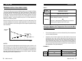
Motor Curves .................................................................... 9
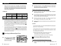
Temperature Probes ......................................................... 11
Heating Options ................................................................ 14
CHANGING THE PARAMETER SETTINGS ...................... 15
The Meaning of a Flashing Display ................................... 15
Locking the Parameters Settings ...................................... 15
TEMPERATURE SETTINGS ............................................. 16
Temperature Units ............................................................ 16
Viewing Temperatures ...................................................... 16
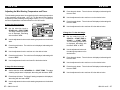
Temperature Set Point ...................................................... 19
Temperature Curve ........................................................... 20
VENTILATION SETTINGS ................................................. 24
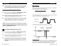
Cooling Operation............................................................. 24
Minimum Ventilation Cycle ................................................ 28
Ventilation Settings ........................................................... 30
Minimum Ventilation Speed Curve .................................... 34
Mist Cooling ..................................................................... 39
NATURAL VENTILATION .................................................. 42
Principle of Operation ....................................................... 42
Curtain Operating Time Compensation ............................. 43
Settings ............................................................................ 44
HEATER SETTINGS .......................................................... 47
Staged Heaters ................................................................ 47
Zoned Heaters .................................................................. 49
TEST MODE ....................................................................... 52
ALARM SETTINGS ............................................................ 53
TROUBLESHOOTING GUIDE ........................................... 55
TECHNICAL SPECIFICATIONS ........................................ 60
FACTORY SETTINGS ........................................................ 61
2 QM 1312.rev.05
We strongly recommend installing supplementary natural
ventilation, a failure alarm system as well as a back-up thermostat on at least one cooling stage (refer to the wiring
diagram enclosed with this user's manual to connect the thermostat).
Although fuses at the input and outputs of the controller protect
its circuits in case of an overload or overvoltage, we
recommend installing an additional protection device on the
supply circuit as well as an external relay on all ON-OFF stages to prolong the life of the controller.
The room temperature where the controller is located MUST
ALWAYS REMAIN BETWEEN 32°F AND 104°F (0°C TO 40°C).
To avoid exposing the controller to harmful gases or excessive humidity, it is preferable to install it in a corridor.
DO NOT SPRAY WATER ON THE CONTROLLER
FOR CUSTOMER USE
Enter below the serial number located
on the side of the controller and retain
this information for future reference.
Model number:
Serial number:
Date installed:
___SS 5124___
_____________
_____________
QM 1312.rev.05
3