1
Hybrid IP-PBX
Feature Guide
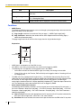
Model No.
KX-TDA50
Thank you for purchasing a Panasonic Hybrid IP-PBX.
Please read this manual carefully before using this product and save this manual for future use.
KX-TDA50: MPR Version 2.0
Introduction
About the Feature Guide
The Feature Guide is designed to serve as an overall reference describing the features of the Panasonic
Hybrid IP-PBX. It explains what the Hybrid IP-PBX can do, as well as how to obtain the most of its many
features and facilities.
The Feature Guide is divided into the following sections:
Section 1 Call Handling Features
Describes the call handling features of the Hybrid IP-PBX.
Section 2 System Configuration and Administration Features
Describes the features which allow the Hybrid IP-PBX to be configured and administered to suit the needs
of its users.
Section 3 Programming Instructions
Serves as an overall system programming reference for the Hybrid IP-PBX.
Section 4 KX-TDA50 Maintenance Console Operating Instructions
Serves as reference operating instructions when using the Panasonic KX-TDA50 Maintenance Console
software to program the Hybrid IP-PBX.
Section 5 Appendix
Provides tables which describe the resource capacity of the Hybrid IP-PBX, as well as its different tones and
ring tones.
Index
An alphabetical listing of features and terms, as well as the page numbers of related sections.
References Found in the Feature Guide
Installation Manual References
The Hybrid IP-PBX Installation Manual provides instructions detailing the installation and maintenance of
the PBX. Sections from the Installation Manual are listed throughout the Feature Guide for your reference.
Feature Guide References
Related sections of the Feature Guide are listed for your reference.
User Manual References
The Hybrid IP-PBX User Manual describes how users can access commonly used PBX features and
functions with their proprietary telephones (PTs), single line telephones (SLTs), portable stations (PSs), and
DSS Consoles. Sections from the User Manual are listed throughout the Feature Guide for your reference.
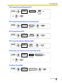
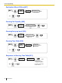
PT Programming References
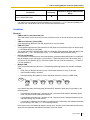
Commonly used settings can be programmed using a display PT (→ 2.3.2 PT Programming). These PT
programming items are noted throughout the Feature Guide for your reference by title and program number.
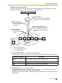
The following is an example of a PT Programming reference:
2
Feature Guide
"Idle extensions are automatically searched for according to a preprogrammed hunting type (→ Idle
Extension Hunting Type [680])."
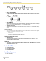
Links to Other Pages and Manuals
If viewing this Feature Guide with a PC, certain items are linked to different sections of the Feature Guide
and other Hybrid IP-PBX manuals. Click on a link to jump to that section.
Linked items include:
•
Installation Manual References
•
Feature Guide References
•
User Manual References
•
PT Programming References
Notes
•
•
Certain PTs, features, and optional service cards are not available in some areas. Consult your certified
Panasonic dealer for more information.
Every system programming setting can be accessed using a PC and the Panasonic KX-TDA50
Maintenance Console software (→ 2.3.1 PC Programming). For programming details, refer to the online help which is installed along with KX-TDA50 Maintenance Console (→ 3.2.1 Installing and Starting
KX-TDA50 Maintenance Console).
WARNING
Unplug the PBX from the AC outlet if it emits smoke, an abnormal smell or makes
unusual noise. These conditions can cause fire or electric shock. Confirm that smoke
has stopped and contact an authorized Panasonic Factory Service Center.
Trademarks
•
•
•
•
Microsoft and Windows are either registered trademarks or trademarks of Microsoft Corporation in the
United States and/or other countries.
Intel and Pentium are trademarks or registered trademarks of Intel Corporation or its subsidiaries in the
United States and other countries.
All other trademarks identified herein are the property of their respective owners.
Screen shots reprinted with permission from Microsoft Corporation.
Feature Highlights
Networking Features
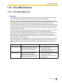
The Hybrid IP-PBX supports the following private networking features:
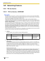
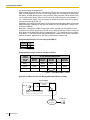
TIE Line Service
PBXs can be connected via a privately leased telephone lines forming a private network. These "TIE
lines" provide a cost-effective way to route calls and communications, and are often used to connect
corporate offices located in different cities.
(→ 1.25.1 TIE Line Service)
QSIG Support
TIE line service can be used on a private network that implements the QSIG protocol (Q.931). QSIG
offers TIE line service as well as advanced caller and called party identification features.
(→ 1.25.2 QSIG Network)
Feature Guide
3
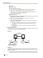
Voice over Internet Protocol (VoIP) Support
The Hybrid-IP PBX can be used on a private network which implements VoIP. On this type of network,
information is sent over the private network in IP packets, which allows voice as well as data to be sent
to other devices in the private network.
(→ 1.25.3 Voice over Internet Protocol (VoIP) Network)
Built-in Small Call Center Features
Extensions can form an incoming call distribution (ICD) group and be used as a small call center which can
take advantage of several features, some of which are highlighted below.
(→ 1.2.2 Incoming Call Distribution (ICD) Group Features)
Queuing
When all available extensions in an ICD group are busy, additional calls can be placed in a queue as
they arrive. While calls are waiting in the queue, callers can hear background music (BGM), an outgoing
message (OGM), etc.
(→ 1.2.2.3 Queuing Feature)
Log-in/Log-out
Members of an ICD group can log-in to or log-out of a group manually. Group members can log-in at
the beginning of a work shift, and log-out at the end of the day. While logged-in, ICD group members
can be allotted a specified amount of time after completing a call during which new calls will not be
received by their extensions, allowing them to finish any necessary paperwork before being eligible to
receive new calls (Wrap-up).
(→ 1.2.2.6 Log-in/Log-out)
VIP Call
The VIP Call feature is one method of making sure that calls from preferred customers or callers are
answered quickly. When using VIP Call mode, ICD groups are assigned a priority, allowing calls in
higher-priority groups to be answered before calls in lower-priority groups.
(→ 1.2.2.4 VIP Call)
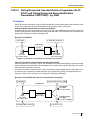
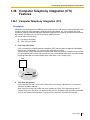
Computer Telephony Integration (CTI) Features
Computers can be connected to the Hybrid-IP PBX to provide extension users with access to advanced
features such as pop-up display of caller information, computer-based speed dialing, etc.
(→ 1.26.1 Computer Telephony Integration (CTI))
PC Phone/PC Console
These Panasonic CTI applications can be used on computers connected to each extension, providing
their respective extension users with powerful and flexible call handling and display features.
Third Party CTI Applications
The Hybrid IP-PBX supports industry standard protocols, allowing third-party CTI applications to be
integrated with the PBX and its extensions.
Voice Mail Features
A Voice Processing System (VPS) can be connected to the Hybrid IP-PBX to provide Voice Mail (VM) and
Automated Attendant (AA) services. A Panasonic VPS which supports DPT (Digital) Integration can be
connected to the Hybrid IP-PBX effortlessly and with minimal setup required. Conventional DTMF (analog)
voice mail systems, including those from other manufacturers, are also supported.
(→ 1.19.1 Voice Mail (VM) Group)
4
Feature Guide
Portable Station (PS) Features
A Panasonic PS can be used in place of a PT to provide wireless access to PBX features and call handling.
When in Wireless XDP Parallel Mode, a PS can share an extension number with a wired telephone, allowing
extension users to use their PSs when they are away from their desks to answer or make calls as if they
were using their wired telephones.
(→ 1.20 Portable Station (PS) Features)
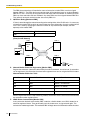
Paralleled Telephone Features
By connecting telephones in parallel, you can increase the number of telephones connected to the PBX
without adding additional extension cards.
(→ 1.10.9 Paralleled Telephone)
Parallel Mode
An SLT can be connected to an analog proprietary telephone (APT) or digital proprietary telephone
(DPT) which is connected to a Super Hybrid port of the PBX. The SLT shares the same extension
number with the APT or DPT.
EXtra Device Port (XDP) Mode
An SLT can be connected to a DPT which is connected to a Super Hybrid port of the PBX. Unlike
parallel mode, XDP mode allows each telephone to act as an independent extension with its own
extension number.
Digital XDP
A DPT can be connected to another DPT which is connected to a DPT port or a Super Hybrid port of
the PBX. Similar to XDP mode, each DPT acts as an independent extension with its own extension
number.
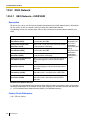
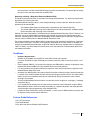
Hospitality Features
This PBX has several features that support its use in a hotel-type environment. Extensions corresponding
to guest rooms can be "checked in" or "checked out" by a designated hotel operator, who can also check
or set wake-up calls. (→ 1.22.1 Hospitality Features—SUMMARY)
Feature Guide
5
List of Abbreviations
AA
Automated Attendant
APT
Analog Proprietary Telephone
ARS
Automatic Route Selection
B
BGM
Background Music
C
CLI
Calling Line Identification
CLIP
Calling Line Identification Presentation
CLIR
Calling Line Identification Restriction
CNIP
Calling Name Identification Presentation
CNIR
Calling Name Identification Restriction
COLP
Connected Line Identification Presentation
COLR
Connected Line Identification Restriction
CONP
Connected Name Identification Presentation
CONR
Connected Name Identification Restriction
COS
Class of Service
CPC
Calling Party Control
CS
Cell Station
CTI
Computer Telephony Integration
DIL
Direct In Line
DISA
Direct Inward System Access
DND
Do Not Disturb
DPT
Digital Proprietary Telephone
DSS
Direct Station Selection
DTMF
Dual Tone Multi-Frequency
E
EFA
External Feature Access
F
FWD
Call Forwarding
G
G-CO
Group-CO
G-DN
Group Directory Number
ICD
Incoming Call Distribution
IRNA
Intercept Routing—No Answer
L-CO
Loop-CO
LCS
Live Call Screening
OGM
Outgoing Message
OHCA
Off-hook Call Announcement
A
D
I
L
O
6
Feature Guide
P
PIN
Personal Identification Number
PS
Portable Station
PT
Proprietary Telephone
S-CO
Single-CO
SLT
Single Line Telephone
SMDR
Station Message Detail Recording
TAFAS
Trunk Answer from Any Station
TRG
CO Line Group
TRS
Toll Restriction
U
UCD
Uniform Call Distribution
V
VM
Voice Mail
VoIP
Voice over Internet Protocol
VPS
Voice Processing System
XDP
eXtra Device Port
S
T
X
Feature Guide
7
Table of Contents
1
8
Call Handling Features......................................................................... 17
1.1
1.1.1
Incoming Call Features..................................................................................................18
Incoming CO Line Call Features ......................................................................................18
1.1.1.1
1.1.1.2
1.1.1.3
1.1.1.4
1.1.1.5
Incoming CO Line Call Features—OVERVIEW .............................................................................................. 18
Direct In Line (DIL) .......................................................................................................................................... 20
Calling Line Identification (CLI) Distribution..................................................................................................... 21
Intercept Routing ............................................................................................................................................. 22
Intercept Routing—No Destination .................................................................................................................. 24
1.1.2
Internal Call Features.......................................................................................................25
1.1.2.1
1.1.2.2
Internal Call Features—OVERVIEW ............................................................................................................... 25
Internal Call Block............................................................................................................................................ 26
1.1.3
Incoming Call Indication Features....................................................................................27
1.1.3.1
1.1.3.2
1.1.3.3
Incoming Call Indication Features—OVERVIEW ............................................................................................ 27
Ring Tone Pattern Selection ............................................................................................................................ 27
Call Waiting ..................................................................................................................................................... 28
1.2
1.2.1
1.2.2
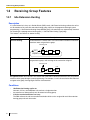
Receiving Group Features ............................................................................................30
Idle Extension Hunting .....................................................................................................30
Incoming Call Distribution (ICD) Group Features.............................................................31
1.2.2.1
1.2.2.2
1.2.2.3
1.2.2.4
1.2.2.5
1.2.2.6
1.2.2.7
Incoming Call Distribution (ICD) Group Features—OVERVIEW ..................................................................... 31
Group Call Distribution .................................................................................................................................... 35
Queuing Feature.............................................................................................................................................. 37
VIP Call............................................................................................................................................................ 40
Overflow Feature ............................................................................................................................................. 41
Log-in/Log-out ................................................................................................................................................. 42
Supervisory Feature ........................................................................................................................................ 45
1.3
1.3.1
Call Forwarding (FWD)/Do Not Disturb (DND) Features.............................................47
Call Forwarding (FWD)/Do Not Disturb (DND).................................................................47
1.3.1.1
1.3.1.2
1.3.1.3
Call Forwarding (FWD)/Do Not Disturb (DND)—OVERVIEW ......................................................................... 47
Call Forwarding (FWD).................................................................................................................................... 49
Do Not Disturb (DND)...................................................................................................................................... 53
1.4
1.4.1
Answering Features.......................................................................................................54
Answering Features .........................................................................................................54
1.4.1.1
1.4.1.2
1.4.1.3
1.4.1.4
Answering Features—OVERVIEW.................................................................................................................. 54
Line Preference—Incoming ............................................................................................................................. 54
Call Pickup....................................................................................................................................................... 55
Hands-free Answerback .................................................................................................................................. 56
1.5
1.5.1
1.5.2
1.5.3
1.5.4
Making Call Features .....................................................................................................58
Predialing .........................................................................................................................58
Automatic Extension Release ..........................................................................................58
Intercom Call ....................................................................................................................58
CO Line Call Features......................................................................................................59
1.5.4.1
1.5.4.2
1.5.4.3
1.5.4.4
1.5.4.5
1.5.4.6
1.5.4.7
CO Line Call Features—OVERVIEW .............................................................................................................. 59
Emergency Call ............................................................................................................................................... 60
Account Code Entry......................................................................................................................................... 60
Dial Type Selection.......................................................................................................................................... 61
Pause Insertion................................................................................................................................................ 62
Host PBX Access Code (Access Code to the Telephone Company from a Host PBX) .................................. 62
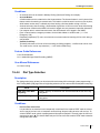
Special Carrier Access Code........................................................................................................................... 64
1.5.5
Seizing a Line Features ...................................................................................................64
1.5.5.1
1.5.5.2
1.5.5.3
Seizing a Line Features—OVERVIEW............................................................................................................ 64
Line Preference—Outgoing ............................................................................................................................. 64
CO Line Access............................................................................................................................................... 65
1.6
Memory Dialing Features ..............................................................................................68
Feature Guide
1.6.1
Memory Dialing Features................................................................................................. 68
1.6.1.1
1.6.1.2
1.6.1.3
1.6.1.4
1.6.1.5
1.6.1.6
Memory Dialing Features—OVERVIEW ..........................................................................................................68
One-touch Dialing ............................................................................................................................................69
Last Number Redial .........................................................................................................................................70
Speed Dialing—Personal/System ....................................................................................................................70
Quick Dialing....................................................................................................................................................71
Hot Line............................................................................................................................................................72
1.7
1.7.1
1.7.2
1.7.3
1.7.4
Busy Line/Busy Party Features .................................................................................... 73
Automatic Callback Busy (Camp-on) ............................................................................... 73
Executive Busy Override.................................................................................................. 73
Call Monitor...................................................................................................................... 74
Second Call Notification to Busy Extension ..................................................................... 75
1.7.4.1
1.7.4.2
1.7.4.3
1.7.4.4
Second Call Notification to Busy Extension—OVERVIEW ..............................................................................75
Call Waiting Tone .............................................................................................................................................76
Off-hook Call Announcement (OHCA) .............................................................................................................76
Whisper OHCA ................................................................................................................................................77
1.8
1.8.1
1.8.2
1.8.3
1.8.4
1.8.5
1.9
1.9.1
1.10
1.10.1
1.10.2
1.10.3
1.10.4
1.10.5
1.10.6
1.10.7
1.10.8
1.10.9
1.10.10
1.11
1.11.1
1.12
1.12.1
1.12.2
1.12.3
1.12.4
1.12.5
1.13
1.13.1
Toll Restriction (TRS) Features .................................................................................... 78
Toll Restriction (TRS) ....................................................................................................... 78
Extension Dial Lock ......................................................................................................... 82
Dial Tone Transfer............................................................................................................ 83
Walking COS ................................................................................................................... 84
Verified Code Entry .......................................................................................................... 84
Automatic Route Selection (ARS) Features ................................................................ 87
Automatic Route Selection (ARS).................................................................................... 87
Conversation Features .................................................................................................. 93
Hands-free Operation ...................................................................................................... 93
Off-hook Monitor .............................................................................................................. 93
Mute ................................................................................................................................. 93
Headset Operation........................................................................................................... 94
Data Line Security............................................................................................................ 95
Flash/Recall/Terminate .................................................................................................... 95
External Feature Access (EFA)........................................................................................ 96
CO Line Call Limitation .................................................................................................... 96
Paralleled Telephone ....................................................................................................... 98
Calling Party Control (CPC) Signal Detection................................................................ 100
Transferring Features .................................................................................................. 101
Call Transfer .................................................................................................................. 101
Holding Features.......................................................................................................... 103
Call Hold ........................................................................................................................ 103
Call Park ........................................................................................................................ 104
Call Splitting ................................................................................................................... 105
Music on Hold ................................................................................................................ 106
Consultation Hold........................................................................................................... 107
Conference Features ................................................................................................... 108
Conference Features ..................................................................................................... 108
1.13.1.1
1.13.1.2
1.13.1.3
Conference Features—OVERVIEW ..............................................................................................................108
Conference ....................................................................................................................................................108
Privacy Release .............................................................................................................................................109
1.14
1.14.1
1.15
1.15.1
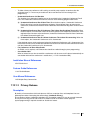
Paging Features ........................................................................................................... 111
Paging.............................................................................................................................111
Optional Device Features............................................................................................ 113
Doorphone Call .............................................................................................................. 113
Feature Guide
9
10
1.15.2
1.15.3
1.15.4
1.15.5
1.15.6
1.15.7
1.15.8
1.15.9
1.16
1.16.1
1.16.2
1.17
1.17.1
1.17.2
1.18
1.18.1
1.18.2
1.18.3
1.18.4
1.19
1.19.1
1.19.2
1.19.3
1.20
1.20.1
1.20.2
1.20.3
1.20.4
1.20.5
1.21
1.21.1
1.21.2
1.22
1.22.1
1.22.2
1.23
1.23.1
1.23.2
1.23.3
1.23.4
1.23.5
1.24
1.24.1
1.24.2
1.25
1.25.1
Door Open...................................................................................................................... 114
Trunk Answer From Any Station (TAFAS) ...................................................................... 114
Background Music (BGM) .............................................................................................. 115
Outgoing Message (OGM) ............................................................................................. 115
Direct Inward System Access (DISA)............................................................................. 117
Automatic Fax Transfer .................................................................................................. 123
External Sensor.............................................................................................................. 124
External Relay Control ................................................................................................... 125
Caller ID Features......................................................................................................... 127
Caller ID ......................................................................................................................... 127
Incoming Call Log .......................................................................................................... 131
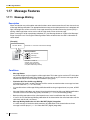
Message Features ........................................................................................................ 134
Message Waiting............................................................................................................ 134
Absent Message ............................................................................................................ 135
Proprietary Telephone (PT) Features ......................................................................... 137
Fixed Buttons ................................................................................................................. 137
Flexible Buttons.............................................................................................................. 139
LED Indication................................................................................................................ 141
Display Information ........................................................................................................ 143
Voice Mail Features ...................................................................................................... 145
Voice Mail (VM) Group ................................................................................................... 145
Voice Mail DPT (Digital) Integration ............................................................................... 147
Voice Mail DTMF Integration.......................................................................................... 153
Portable Station (PS) Features.................................................................................... 159
Portable Station (PS) Connection .................................................................................. 159
PS Ring Group ...............................................................................................................160
Wireless XDP Parallel Mode .......................................................................................... 164
PS Directory ................................................................................................................... 166
PS Feature Buttons........................................................................................................ 166
Administrative Information Features ......................................................................... 167
Station Message Detail Recording (SMDR) ...................................................................167
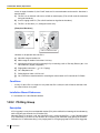
Printing Message ........................................................................................................... 173
Hospitality Features ..................................................................................................... 174
Hospitality Features—SUMMARY.................................................................................. 174
Room Status Control ...................................................................................................... 174
Extension Controlling Features.................................................................................. 176
Extension Personal Identification Number (PIN)............................................................ 176
Extension Feature Clear ................................................................................................ 177
Walking Extension.......................................................................................................... 178
Timed Reminder.............................................................................................................178
Remote Extension Control by User................................................................................179
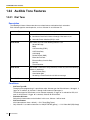
Audible Tone Features................................................................................................. 180
Dial Tone ........................................................................................................................180
Confirmation Tone .......................................................................................................... 181
Networking Features....................................................................................................182
TIE Line Service.............................................................................................................182
1.25.1.1
1.25.1.2
1.25.1.3
TIE Line Service—OVERVIEW ..................................................................................................................... 182
PBX Code Method (Access with PBX Code)................................................................................................. 188
Extension Number Method (Access without PBX Code)............................................................................... 196
1.25.2
QSIG Network ................................................................................................................ 206
1.25.2.1
QSIG Network—OVERVIEW ........................................................................................................................ 206
Feature Guide
1.25.2.2
1.25.2.3
Calling/Connected Line Identification Presentation (CLIP/COLP) and Calling/Connected Name Identification
Presentation (CNIP/CONP)—by QSIG ..........................................................................................................207
Network Direct Station Selection (NDSS) (KX-TDA5920 required)................................................................209
1.25.3
1.26
1.26.1
Voice over Internet Protocol (VoIP) Network.................................................................. 212
Computer Telephony Integration (CTI) Features ...................................................... 213
Computer Telephony Integration (CTI)........................................................................... 213
2
System Configuration and Administration Features ...................... 215
2.1
2.1.1
2.2
2.2.1
2.2.2
2.2.3
2.2.4
2.2.5
2.2.6
2.3
2.3.1
2.3.2
2.3.3
2.3.4
2.3.5
2.3.6
2.3.7
2.4
2.4.1
2.4.2
2.4.3
3
Programming Instructions................................................................. 245
3.1
3.1.1
3.1.2
3.1.3
3.2
3.2.1
3.3
3.3.1
3.3.2
3.3.3
3.3.4
3.3.5
3.3.6
3.3.7
3.3.8
3.3.9
3.3.10
3.3.11
4
System Configuration—Hardware.............................................................................. 216
Extension Port Configuration ......................................................................................... 216
System Configuration—Software ............................................................................... 217
Class of Service (COS).................................................................................................. 217
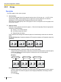
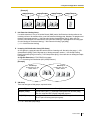
Group ............................................................................................................................. 218
Tenant Service ............................................................................................................... 220
Time Service .................................................................................................................. 224
Operator Features.......................................................................................................... 228
Manager Features.......................................................................................................... 228
System Data Control.................................................................................................... 231
PC Programming ........................................................................................................... 231
PT Programming............................................................................................................ 233
Quick Setup ................................................................................................................... 234
Automatic Time Adjustment ........................................................................................... 235
Flexible Numbering/Fixed Numbering............................................................................ 236
Floating Extension ......................................................................................................... 240
Software Upgrading ....................................................................................................... 241
Fault Recovery/Diagnostics........................................................................................ 242
Power Failure Transfer................................................................................................... 242
Power Failure Restart .................................................................................................... 242
Local Alarm Information ................................................................................................. 242
Introduction .................................................................................................................. 246
Introduction .................................................................................................................... 246
Password Security ......................................................................................................... 246
Entering Characters ....................................................................................................... 248
PC Programming.......................................................................................................... 251
Installing and Starting KX-TDA50 Maintenance Console............................................... 251
PT Programming .......................................................................................................... 255
Programming Instructions .............................................................................................. 255
Basic Programming........................................................................................................ 257
System Management Programming .............................................................................. 259
Time Programming......................................................................................................... 261
TRS/ARS Programming................................................................................................. 263
CO Line Programming ................................................................................................... 265
COS Programming......................................................................................................... 269
Extension Programming................................................................................................. 271
Resource/Interface Programming .................................................................................. 277
SMDR & Maintenance Programming............................................................................. 278
Card Programming......................................................................................................... 280
KX-TDA50 Maintenance Console Operating Instructions .............. 281
Feature Guide
11
4.1
4.1.1
4.1.2
4.1.3
4.1.4
4.1.5
4.1.6
4.2
4.2.1
4.2.2
4.2.3
4.2.4
4.2.5
4.2.6
4.3
4.3.1
4.3.2
4.3.3
4.3.4
4.4
4.4.1
4.4.2
4.4.3
4.4.4
4.4.5
4.4.6
4.5
4.5.1
4.5.2
4.5.3
4.5.4
4.5.5
4.5.6
4.5.7
4.5.8
4.5.9
4.5.10
4.6
4.6.1
4.7
4.7.1
4.7.2
4.7.3
4.7.4
4.7.5
4.7.6
4.7.7
4.7.8
4.7.9
4.7.10
12
Introduction .................................................................................................................. 282
Software Modes .............................................................................................................282
Status Bar....................................................................................................................... 282
Access Levels ................................................................................................................ 282
Standard Buttons............................................................................................................ 285
Card Status .................................................................................................................... 285
Display Options .............................................................................................................. 286
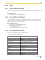
File ................................................................................................................................. 287
File—New....................................................................................................................... 287
File—Open ..................................................................................................................... 287
File—Close..................................................................................................................... 288
File—Save...................................................................................................................... 288
File—Save As ................................................................................................................ 288
File—eXit........................................................................................................................288
Connect......................................................................................................................... 290
Connect—RS-232C ....................................................................................................... 290
Connect—USB...............................................................................................................290
Connect—Modem .......................................................................................................... 291
Connect—Disconnect ....................................................................................................292
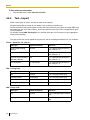
Tool................................................................................................................................ 293
Tool—SD memory backup ............................................................................................. 293
Tool—NDSS Link Data Clear .........................................................................................293
Tool—Extension List View .............................................................................................. 293
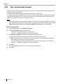
Tool—Import................................................................................................................... 294
Tool—Export................................................................................................................... 295
Tool—System data Convert ........................................................................................... 296
Utility ............................................................................................................................. 297
Utility—Diagnosis ........................................................................................................... 297
Utility—File Transfer PC to PBX (SD Card) ...................................................................298
Utility—File Transfer PBX (SD Card) to PC ...................................................................299
Utility—SD Card File View and Load ............................................................................. 300
Utility—Message File Transfer PC to PBX .....................................................................301
Utility—Message File Transfer PBX to PC .....................................................................301
Utility—Error Log............................................................................................................ 301
Utility—CS Information................................................................................................... 302
Utility—PS Information ................................................................................................... 303
Utility—System Reset—Reset by the Command ........................................................... 304
Help ............................................................................................................................... 306
FAQ ................................................................................................................................ 306
Configuration [1] .......................................................................................................... 315
Slot [1-1]......................................................................................................................... 315
Slot [1-1] MPR Card Property ........................................................................................ 317
Slot [1-1] Extension Card Property................................................................................. 318
Slot [1-1] LCO Card Property .........................................................................................321
Slot [1-1] IP-GW Card Property...................................................................................... 329
Slot [1-1] DPH Card Property.........................................................................................330
Slot [1-1] DPH Port Command ....................................................................................... 331
Slot [1-1] Card Command .............................................................................................. 332
Portable Station [1-2]...................................................................................................... 334
Option [1-3] .................................................................................................................... 337
Feature Guide
4.7.11
4.7.12
4.7.13
4.7.14
4.7.15
4.7.16
4.7.17
4.8
4.8.1
4.8.2
4.8.3
4.8.4
4.8.5
4.8.6
4.8.7
4.8.8
4.8.9
4.8.10
4.8.11
4.8.12
4.8.13
4.8.14
4.8.15
4.8.16
4.8.17
4.8.18
4.8.19
4.8.20
4.8.21
4.8.22
4.8.23
4.8.24
4.8.25
4.8.26
4.8.27
4.9
4.9.1
4.9.2
4.9.3
4.9.4
4.9.5
4.9.6
4.9.7
4.9.8
4.9.9
4.9.10
4.9.11
4.9.12
4.9.13
4.9.14
LCO Port [1-4]................................................................................................................ 337
LCO Port [1-4] Port Command....................................................................................... 341
Extension Port [1-5] ....................................................................................................... 341
Extension Port [1-5] Port Command .............................................................................. 347
Extension Port [1-5] Port Type View .............................................................................. 348
IP-GW Port [1-6] ............................................................................................................ 349
IP-GW Port [1-6] Port Command ................................................................................... 350
System [2]..................................................................................................................... 351
Date & Time/Daylight Saving—Date & Time [2-1-1] ...................................................... 351
Date & Time / Daylight Saving—Daylight Saving [2-1-2] ............................................... 351
PBX Operator [2-2] ........................................................................................................ 353
BGM / Music on Hold [2-3]............................................................................................. 354
Timers & Counters—CO / Extension [2-4-1] .................................................................. 355
Timers & Counters—DISA/DPH/CONF/T. Reminder [2-4-2].......................................... 360
Timers & Counters—Miscellaneous [2-4-3] ................................................................... 367
Time Service—Week Table [2-5-1] ................................................................................ 371
Time Service—Holiday Table [2-5-2].............................................................................. 377
Numbering Plan—Extension [2-6-1] .............................................................................. 379
Numbering Plan—Feature [2-6-2].................................................................................. 380
Numbering Plan—Other PBX Extension [2-6-3] ............................................................ 403
Numbering Plan—Quick Dialing [2-6-4] ......................................................................... 404
Numbering Plan—B/NA DND Call Feature [2-6-5] ........................................................ 404
Class of Service—COS Settings [2-7-1] ........................................................................ 407
Class of Service—External Call Block [2-7-2]................................................................ 417
Class of Service—Internal Call Block [2-7-3] ................................................................. 418
Ring Tone Patterns—Call from CO [2-8-1]..................................................................... 418
Ring Tone Patterns—Call from Doorphone [2-8-2] ........................................................ 419
Ring Tone Patterns—Call from Others [2-8-3] ............................................................... 419
System Options—Option 1 [2-9-1] ................................................................................. 421
System Options—Option 2 [2-9-2] ................................................................................. 425
System Options—Option 3 [2-9-3] ................................................................................. 430
System Options—Option 4 [2-9-4] ................................................................................. 435
CTI [2-10] ....................................................................................................................... 438
Audio Gain—Paging/MOH [2-11-1]................................................................................ 441
Extension Caller ID [2-12] .............................................................................................. 442
Groups [3]..................................................................................................................... 447
Trunk Group—TRG Settings [3-1-1] .............................................................................. 447
Trunk Group—Local Access Priority [3-1-2]................................................................... 452
Extension Group [3-2] .................................................................................................... 453
Call Pickup Group [3-3].................................................................................................. 454
Paging Group [3-4]......................................................................................................... 455
Incoming Call Distribution Group—Group Settings [3-5-1] ............................................ 458
Incoming Call Distribution Group—Member [3-5-2] ....................................................... 471
Incoming Call Distribution Group—Queuing Time Table [3-5-3] .................................... 473
Extension Hunting Group [3-6]....................................................................................... 473
VM(DPT) Group—System Setting [3-7-1] ...................................................................... 475
VM(DPT) Group—Unit Setting [3-7-2] ........................................................................... 476
VM(DTMF) Group—System Setting [3-8-1] ................................................................... 477
VM(DTMF) Group—Group Setting [3-8-2] ..................................................................... 486
PS Ring Group [3-9]....................................................................................................... 487
Feature Guide
13
4.10
4.10.1
4.10.2
4.10.3
4.10.4
4.10.5
4.10.6
4.10.7
4.10.8
4.10.9
4.10.10
4.10.11
4.10.12
4.10.13
4.10.14
4.10.15
4.10.16
4.10.17
4.11
4.11.1
4.11.2
4.11.3
4.11.4
4.11.5
4.11.6
4.12
4.12.1
4.12.2
4.12.3
4.12.4
4.12.5
4.12.6
4.12.7
4.12.8
4.13
4.13.1
4.13.2
4.13.3
4.13.4
4.14
4.14.1
4.14.2
4.14.3
4.14.4
4.14.5
4.14.6
4.15
4.15.1
4.15.2
4.15.3
14
Extension [4]................................................................................................................. 490
Wired Extension—Extension Settings [4-1-1] ................................................................ 490
Wired Extension—Extension Settings [4-1-1] CLIP Generate ....................................... 522
Wired Extension—FWD/DND [4-1-2] ............................................................................. 524
Wired Extension—Speed Dial [4-1-3]............................................................................. 528
Wired Extension—Flexible Key [4-1-4] .......................................................................... 528
Wired Extension—Flexible Key [4-1-4] Flexible Key Data Copy ....................................538
Wired Extension—PF Key [4-1-5] .................................................................................. 538
Wired Extension—NDSS Link Data - Send [4-1-6] ........................................................539
Portable Station—Extension Settings [4-2-1] ................................................................. 540
Portable Station—Extension Settings [4-2-1] CLIP Generate ........................................ 559
Portable Station—FWD/DND [4-2-2] ..............................................................................561
Portable Station—Flexible Key [4-2-3] ........................................................................... 565
Portable Station—Flexible Key [4-2-3] Flexible Key Data Copy..................................... 574
Portable Station—NDSS Link Data - Send [4-2-4] ......................................................... 574
DSS Console—Main [4-3-1]........................................................................................... 574
DSS Console—Flexible Key [4-3-2] ............................................................................... 575
DSS Console—Flexible Key [4-3-2] Flexible Key Data Copy ........................................ 585
Optional Device [5]....................................................................................................... 586
Doorphone [5-1] .............................................................................................................586
External Pager [5-2] ....................................................................................................... 588
DISA—System Setting [5-3-1]........................................................................................ 589
DISA—Message Setting [5-3-2] ..................................................................................... 592
External Relay [5-4]........................................................................................................ 594
External Sensor [5-5] ..................................................................................................... 596
Feature [6]..................................................................................................................... 599
Speed Dialing & Caller ID—Main Table [6-1-1] .............................................................. 599
Speed Dialing & Caller ID—Caller ID Modification [6-1-2] ............................................. 600
Emergency Dial [6-2]...................................................................................................... 602
Verified Code [6-3] ......................................................................................................... 602
Second Dial Tone [6-4]................................................................................................... 604
Absent Message [6-5] ....................................................................................................605
Tenant [6-6] .................................................................................................................... 606
Hotel [6-8]....................................................................................................................... 607
TRS [7]........................................................................................................................... 610
Denied Code [7-1] .......................................................................................................... 610
Exception Code [7-2]...................................................................................................... 610
Special Carrier [7-3] ....................................................................................................... 611
Miscellaneous [7-4] ........................................................................................................ 611
ARS [8] ..........................................................................................................................614
System Setting [8-1]....................................................................................................... 614
Leading Number [8-2] ....................................................................................................615
Routing Plan Time [8-3].................................................................................................. 616
Routing Plan Priority [8-4] .............................................................................................. 617
Carrier [8-5] .................................................................................................................... 617
Leading Number Exception [8-6].................................................................................... 620
Private Network [9]....................................................................................................... 622
TIE Table [9] ................................................................................................................... 622
Network BLF Data Transfer [9-2] ................................................................................... 624
Network Operator (VoIP) [9-3]........................................................................................ 625
Feature Guide
4.15.4
4.16
4.16.1
4.16.2
4.16.3
4.17
4.17.1
4.17.2
4.17.3
4.17.4
5
NDSS Key Table [9-4] .................................................................................................... 625
CO & Incoming Call [10] .............................................................................................. 628
CO Line Setting [10-1] ................................................................................................... 628
DIL Table & Port Setting [10-2] ...................................................................................... 629
Miscellaneous [10-3] ...................................................................................................... 635
Maintenance [11] .......................................................................................................... 637
SMDR [11-1] .................................................................................................................. 637
PT System Program [11-2]............................................................................................. 642
Miscellaneous [11-3] ...................................................................................................... 643
Password Setting [11-4] ................................................................................................. 649
Appendix ............................................................................................. 653
5.1
5.1.1
5.2
5.2.1
5.3
5.3.1
5.3.2
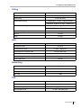
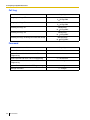
Capacity of System Resources .................................................................................. 654
Capacity of System Resources...................................................................................... 654
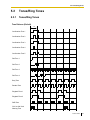
Tones/Ring Tones ........................................................................................................ 657
Tones/Ring Tones .......................................................................................................... 657
Revision History........................................................................................................... 659
MPR Version 1.1 ............................................................................................................ 659
MPR Version 2.0 ............................................................................................................ 659
Index .......................................................................................................... 661
Feature Guide
15
16
Feature Guide
Section
1
Call Handling Features
Feature Guide
17
1.1 Incoming Call Features
1.1
Incoming Call Features
1.1.1
Incoming CO Line Call Features
1.1.1.1
Incoming CO Line Call Features—OVERVIEW
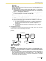
Description
Each CO line functions as either a public line or a private line. Private lines are used to connect different
PBXs and form a private network (→ 1.25.1 TIE Line Service), while public lines connect a PBX to a public
network, i.e., the telephone company. Certain PBX features are available depending on the networking type
(public or private) of each CO line.
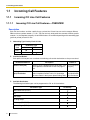
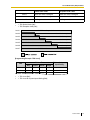
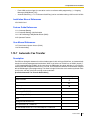
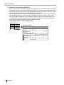
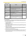
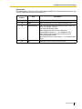
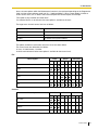
1. Networking Type Used by Each CO Line
CO Line
Card
Networking Type
Public
Private
LCOT
IP-GW
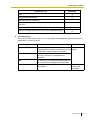
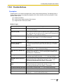
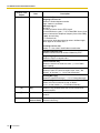
2. Distribution Method
Each public CO line port uses a method of distributing calls to their destinations as they are received.
Distribution Method
Description
Direct In Line (DIL)
Details in
Directs a call to a preprogrammed destination, such • 1.1.1.2 Direct In
as an operator, based on the CO line carrying the
Line (DIL)
call.
Calling Line Identification Directs a call to its preprogrammed destination if the • 1.1.1.3 Calling
(CLI) Distribution
caller's telephone number and its CLI destination
Line Identification
has been stored in the System Speed Dialing Table. (CLI) Distribution
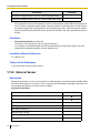
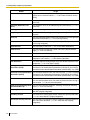
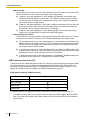
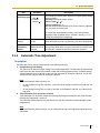
3. Available Destination
The following destination types can be programmed as DIL or CLI destinations.
Destination Type
Wired Extension (PT/SLT)
PS
ICD Group
PS Ring Group
VM Group (DTMF/DPT)
External Pager (TAFAS)
18
Feature Guide
Availability
1.1 Incoming Call Features
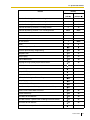
Destination Type
Availability
DISA
Analog Remote Maintenance
Idle Line Access no. + Phone no.
CO Line Group Access no. + CO Line Group no. +
Phone no.
Extension of Another PBX (via TIE Line, Access with PBX Code)
Extension of Another PBX (via TIE Line, Access without PBX Code)
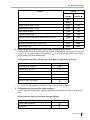
4. Intercept Routing
After a call has been directed to its DIL or CLI destination, the following Intercept Routing features, if
programmed, can redirect the call.
Type
Description
Details in
No Answer (IRNA)
If a called party does not answer a call within a
• 1.1.1.4 Intercept
preprogrammed time period (Intercept time), the call Routing
is redirected to a preprogrammed destination.
Busy
If a called party is already handling another call, the
new call is redirected to a preprogrammed
destination.
DND
If a called party is in Do Not Disturb (DND) mode, the
call is redirected to a preprogrammed destination.
No Destination
If a destination is not assigned, the call is redirected • 1.1.1.5 Intercept
to an operator.
Routing—No
Destination
Feature Guide
19
1.1 Incoming Call Features
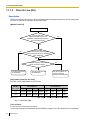
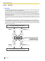
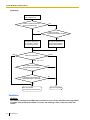
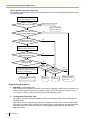
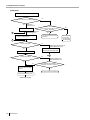
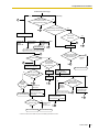
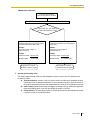
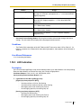
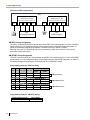
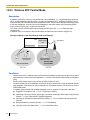
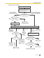
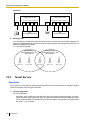
1.1.1.2
Direct In Line (DIL)
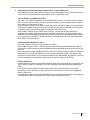
Description
Directs an incoming public CO line call to a preprogrammed destination based on the CO line carrying the
call. Each CO line has a destination for each time mode.
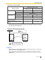
[Method Flowchart]
A CO line call is received.
Does the call have
Caller ID information and is CLI
distribution enabled for the CO line in
the current time mode?
No
Yes
Yes
Has the caller
been stored in the System Speed
Dialing Table and has a CLI destination
been assigned?
No
No
Is a DIL destination assigned
for the current time mode?
Yes
The call is routed to its
CLI destination.
The call is routed to the
DIL destination.
The call is routed to an
operator (Intercept
Routing—No Destination).
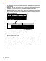
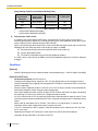
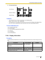
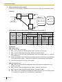
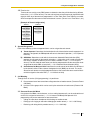
[Programming Example: DIL Table]
The table can be programmed for each CO line.
Port No.
(CO Line No.)
*
CLI Distribution
Day
Lunch
Break
DIL Destination*
Night
Day
Lunch
Break
Night
01
Enable Disable Enable Disable
101
100
101
100
02
Enable Disable Disable Disable
102
100
102
100
→ DIL 1:1 Destination [450]
In this example:
If a CO line call is received on CO line 01:
In day mode: Calling Line Identification (CLI) distribution is enabled. The call is routed to its CLI destination,
20
Feature Guide
1.1 Incoming Call Features
if assigned. If not assigned, the call is routed to the Direct In Line (DIL) destination, extension 101.
In lunch mode: CLI distribution is disabled. The call is routed to the DIL destination, extension 100.
Note
Tenant numbers and VPS trunk (CO line) group numbers (not shown here) can also be programmed
in the DIL Table.
The tenant number programmed here is used only to determine the Time Table used by each CO line;
selecting tenant 3 means the CO line will use Time Table 3, for example. The VPS trunk (CO line) group
number set here is used to determine the Incoming Call Service and greeting message used by the
Voice Processing System (VPS) during the current time mode. (→ 1.19.2 Voice Mail DPT (Digital)
Integration).
Feature Guide References
1.1.1.3 Calling Line Identification (CLI) Distribution
2.2.4 Time Service
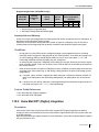
1.1.1.3
Calling Line Identification (CLI) Distribution
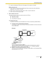
Description
Directs an incoming CO line call to a specific destination when the caller's telephone number matches a
number in the System Speed Dialing Table. Each telephone number in this table can be assigned its own
Calling Line Identification (CLI) destination.
CLI distribution allows you to direct calls from specific people to specific destinations, and has many
applications. For example, you can program the PBX to automatically connect calls from priority clients to
their sales representatives, or automatically connect mobile phone calls from an executive to his or her
assistant.
In order for CLI distribution to function, the PBX must receive Caller ID information from the telephone
company.
CLI distribution works in conjunction with Direct In Line (DIL) distribution; it can be enabled or disabled for
each time mode assigned on each CO line.
When a call has Caller ID information and CLI distribution is enabled for the current time mode, CLI
distribution will direct the call to its destination, ignoring preprogrammed DIL destinations.
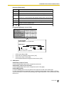
[Programming Example: System Speed Dialing Table]
*1
*2
Location
(System Speed
Dialing No.)
System Speed
Dialing Name*1
Telephone No.*2
CLI Destination
000
ABC Company
912125551234
200
001
XYZ Company
913135551234
300
→ System Speed Dialing Name [002]
→ System Speed Dialing Number [001]
Feature Guide
21
1.1 Incoming Call Features
In this example:
If the caller's telephone number is "1-212-555-1234":
1) The PBX looks for the number in the System Speed Dialing Table. (The CO Line Access number,
"9", is disregarded.) The number is found in location 000.
2) If CLI distribution is enabled in the current time mode for the CO line carrying the call (for DIL
distribution), the call is routed to its CLI destination, extension 200.
Conditions
•
If Automatic Caller ID Modification is used:
Store the modified number in the System Speed Dialing Table.
Feature Guide References
1.1.1.2 Direct In Line (DIL)
1.6.1.4 Speed Dialing—Personal/System
1.16.1 Caller ID
1.1.1.4
Intercept Routing
Description
Redirects an incoming CO line call to a preprogrammed destination when the original destination does not,
or can not, answer the call. There are four types of Intercept Routing, described below.
Type
Description
No Answer (IRNA)
If a called party does not answer a call within a preprogrammed time period
(→ Intercept Time [203]), the call is redirected to a preprogrammed intercept
destination.
Busy
If a called party is already handling a call, new calls are redirected to a
preprogrammed intercept destination.
DND
If a called party is in Do Not Disturb (DND) mode, the call is redirected to a
preprogrammed intercept destination.
No Destination
If a call has no destination (i.e., if a destination is not assigned), the call is
redirected to an operator. (→ 1.1.1.5 Intercept Routing—No Destination)
Intercept Routing redirects calls to destinations based on the original destination of the call, as shown in the
table below. Different intercept destinations can be programmed for each time mode. Note that calls
redirected by Intercept Routing—No Answer/Busy/DND are directed to the same destination, and that the
intercept destination for Intercept Routing—No Destination is always an operator.
When the original destination is:
22
The Available Intercept Destination is:
•
•
Wired Extension (PT/SLT)
PS
The destination assigned to the original extension (→
Extension Intercept Destination [604])
•
ICD Group
The ICD Group Overflow destination assigned to the
group (→ Destination for Overflow Time Expiration
[625]) (→ 1.2.2.5 Overflow Feature)
Feature Guide
1.1 Incoming Call Features
When the original destination is:
The Available Intercept Destination is:
•
•
•
PS Ring Group
VM Group (DTMF/DPT)
External Pager (TAFAS)
The destination assigned to the CO line group
carrying the call (→ CO Line Group Intercept
Destination [470])
•
DISA
The destination assigned to the CO line group
carrying the call* (→ CO Line Group Intercept
Destination [470])
•
•
•
Analog Remote Maintenance
Not assignable (Intercept Routing is not available.)
Idle Line Access no. + Phone no.
CO Line Group Access no. + CO Line Group
no. + Phone no.
Other PBX Extension (TIE with no PBX Code)
Other PBX Extension (TIE with PBX Code)
•
•
*
Intercept Routing will redirect a call only if the Direct Inward System Access (DISA) line is busy. Once
a call reaches the destination extension using the DISA feature, the call can be redirected to the
Intercept Routing destination assigned to that extension.
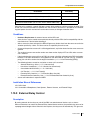
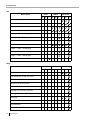
[Available Intercept Destination]
The following can be used as intercept destinations:
Intercept Destination
Availability
Wired Extension (PT/SLT)
PS
ICD Group
PS Ring Group
VM Group (DTMF/DPT)
External Pager (TAFAS)
DISA
Analog Remote Maintenance
Idle Line Access no. + Phone no.
CO Line Group Access no. + CO Line Group no. +
Phone no.
Extension of Another PBX (via TIE Line, Access with PBX Code)
Extension of Another PBX (via TIE Line, Access without PBX Code)
Conditions
•
If the intercept destination is busy or in DND mode and therefore cannot receive the call:
a) When the call was intercepted via Intercept Routing—No Answer, the call is sent back to the
original destination and continues to ring at the original destination until answered.
Feature Guide
23
1.1 Incoming Call Features
b) When the call was intercepted via Intercept Routing—Busy and arrived through a public line, the
call waits at the original destination. If the extension has Call Waiting activated, the user will hear
a call waiting tone. When the call arrived through a private line, the caller hears a busy tone.
c) When the call was intercepted via Intercept Routing—DND and arrived through a public line, the
•
•
call waits at the original destination and it rings. When the call arrived through a private line, the
caller hears a busy tone.
If the intercept destination can, but does not, answer the call:
The call continues to ring at the intercept destination until answered.
Intercept Routing—Busy/DND on/off
Intercept Routing—Busy and Intercept Routing—DND can each be enabled or disabled for the entire
system, through system programming. If enabled, calls will be routed to the appropriate destination.
If disabled, a call to an extension which is busy or in DND mode will be handled as described below,
depending on the type of CO line carrying the call.
a) Public Line: The caller will hear a ringback tone. If busy, the extension will not ring. If in DND mode,
the extension will ring.
b) Private Line: The caller will hear a busy tone.
•
Idle Extension Hunting
If an extension is a member of an idle extension hunting group, calls to that extension will not be
redirected by Intercept Routing—Busy/DND. If the extension is busy or in DND mode, calls to that
extension will be redirected to the next extension in the idle extension hunting group.
Feature Guide References
1.3.1 Call Forwarding (FWD)/Do Not Disturb (DND)
1.1.1.5
Intercept Routing—No Destination
Description
Directs a CO line call to an operator when the call has no assigned destination.
Conditions
•
•
•
Intercept Routing—No Destination on/off
Intercept Routing—No Destination can be enabled or disabled for the entire system, through system
programming. If disabled, the caller will hear a reorder tone.
Note that this feature can only be disabled for calls which arrived on a private CO line; Intercept
Routing—No Destination always functions for public CO line calls.
If an operator is not assigned:
The default intercept destination will be the extension connected to the lowest numbered port, on the
card installed in the lowest numbered slot.
Intercept Routing—No Destination also applies to calls from doorphones.
Feature Guide References
2.2.5 Operator Features
24
Feature Guide
1.1 Incoming Call Features
1.1.2
Internal Call Features
1.1.2.1
Internal Call Features—OVERVIEW
Description
There are two types of internal calls, described below.
Feature
Description
Details in
Intercom Call
A call from one extension to another.
• 1.5.3 Intercom
Call
Doorphone Call
A call made from a doorphone to its preprogrammed
destination, assigned to the doorphone's port, for the
current time mode. (→ 2.2.4 Time Service)
• 1.15.1
Doorphone Call
[Available Destination]
The following destinations can be called internally.
Destination
When calling from
Extension
Doorphone
Wired Extension (PT/SLT)
PS
ICD Group
PS Ring Group
VM Group (DTMF/DPT)
External Pager (TAFAS)
DISA
Analog Remote Maintenance
Idle Line Access no. + Phone no.
CO Line Group Access no. + CO Line Group no. +
Phone no.
Extension of Another PBX (via TIE Line, Access with PBX Code)
Extension of Another PBX (via TIE Line, Access without PBX
Code)
Available
Feature Guide
25
1.1 Incoming Call Features
1.1.2.2
Internal Call Block
Description
Internal calls can be restricted based on the Class of Service (COS) assigned to the caller and to the called
party.
[Programming Example: Internal Call Block]
Called Party
Caller
COS 1
COS 2
COS 3
COS...
Block
Block
Block
COS 1
COS 2
Block
COS 3
Block
Block
In this example:
a) COS 1 can make calls to all extensions.
b) COS 2 can make calls to COS 1 only. (COS 2 cannot make calls to COS 2.)
c) COS 3 can make calls to COS 3 only.
COS 1
Extn. 100
Extn. 101
COS 2
Extn. 102
COS 3
Extn. 103
Extn. 104
Extn. 105
Extn. 106
Conditions
•
•
•
26
Internal Call Block also prohibits certain features, such as Walking Extension and Walking COS, from
being performed between certain extensions.
Any extension can make an Operator Call regardless of the Internal Call Block setting of its COS. (→
2.2.5 Operator Features)
Because each doorphone port is assigned a COS, the Internal Call Block feature can restrict certain
extensions from calling certain doorphones. (→ 1.15.1 Doorphone Call)
Feature Guide
1.1 Incoming Call Features
Feature Guide References
2.2.1 Class of Service (COS)
1.1.3
1.1.3.1
Incoming Call Indication Features
Incoming Call Indication Features—OVERVIEW
Description
Extension telephones can indicate an incoming call in various ways, described below.
Indication Type
Feature
Description
Details in
Ring Tone
Ring Tone
Pattern
Selection
A telephone rings when receiving a call. A
different ring tone pattern can be assigned to
each incoming call type.
Voice-calling
Alternate
Receiving—
Ring/Voice
Proprietary telephone (PT) users can choose • 1.5.3 Intercom
how their telephones receive intercom calls, by Call
selecting to hear ring tones or the caller's voice.
LED
LED Indication
The LED indicator on a PT can indicate the
• 1.18.3 LED
status of different lines using light patterns and Indication
colors.
Display (Caller
Information)
Display
Information
A user's PT can show a variety of information
on the display, such as the line number, the
caller's name and number, the original
destination if the call was forwarded, etc.
External Pager
Trunk Answer
A pager (loudspeaker) can be used to indicate • 1.15.3 Trunk
from Any Station when a call is received, useful in noisy or large Answer From Any
(TAFAS)
workplaces.
Station (TAFAS)
Tone/Voice
during a
Conversation
Call Waiting
1.1.3.2
• 1.1.3.2 Ring
Tone Pattern
Selection
• 1.18.4 Display
Information
When an extension user is on another call, the • 1.1.3.3 Call
Waiting
user can be alerted to a new call by a call
waiting tone, or the caller can speak directly
through the user's handset or built-in speaker.
Ring Tone Pattern Selection
Description
A different ring tone pattern can be assigned to each incoming call type, based on the Ring Tone Pattern
Table of the extension.
There are several programmable Ring Tone Pattern Tables. Each table designates a ring tone for intercom
calls, CO line calls, doorphone calls, etc., and each extension can choose its preferred ring tone pattern by
selecting a table.
Feature Guide
27
1.1 Incoming Call Features
[Ring Tone Patterns]
1 280 ms
Single
Double
Triple
S-Double
[Programming Example: Ring Tone Pattern Table]
Table
No.
Intercom CO Line Call/Hold Doorphone Call
Recall
Call/Hold
Recall
TRG1
TRG... Port 1 Port ...
1
Double
Single
Single
2
Single
Double
Double
Timed
Reminder
Call
Back
LCS
External
Sensor
Conditions
•
"PT Ring off Setting" can be enabled or disabled through system programming. If disabled,
proprietary telephone (PT) users cannot turn the ringer off for their extensions.
1.1.3.3
Call Waiting
Description
A busy extension user can be alerted to a new call by Call Waiting. The busy extension user can then
answer the second call either by disconnecting the current call or placing it on hold.
One of the following notification methods can be assigned for each extension, depending on the type of
telephone being used and the type of call that is waiting.
a)
b)
c)
d)
Call Waiting Tone: A tone is heard through the handset or built-in speaker.
Off-hook Call Announcement (OHCA): The caller's voice is heard through the built-in speaker.
Whisper OHCA: The caller's voice is heard through the handset.
Off: No call waiting notification is given.
Available Notification Method
Call Type
DPT
28
Intercom Call
Call waiting tone/OHCA/Whisper
OHCA/Off
CO Line Call*
Call waiting tone/Off
Feature Guide
Other Telephone
Call waiting tone/Off
1.1 Incoming Call Features
*
Includes CO line calls transferred from another extension or received via an incoming call distribution
(ICD) group, as well as doorphone calls.
This feature is also known as Busy Station Signaling (BSS).
Conditions
•
•
•
•
•
•
An extension in a VM group (DPT/DTMF) cannot receive a call waiting tone. This is to prevent call
waiting tones from interrupting the recording of voice mail messages.
Data Line Security
When an extension user activates Data Line Security, Call Waiting is turned off. (→ 1.10.5 Data Line
Security)
Call Waiting Tone
A proprietary telephone (PT) user can select the preferred call waiting tone through personal
programming (Call Waiting Tone Type Selection).
Caller Information
When an extension receives a call waiting tone, the caller's information will flash on the display for five
seconds, followed by a 10-second pause, then flashes again for five seconds.
Call Waiting from the Telephone Company
Besides the Call Waiting feature provided by the PBX, you can also subscribe to your telephone
company's Call Waiting service and receive call waiting tones from the telephone company's analog
lines. If you do, this external call waiting tone will alert an extension user of another incoming CO line
call that is waiting. The user can answer the second call by disconnecting the current call or placing it
on hold using EFA.
For details, consult your telephone company.
Call Waiting Caller ID (Visual Caller ID)
When using the call waiting tone supplied by the telephone company over analog lines, the caller's
telephone number and name can be received. Either the name or the number will flash on the display
for five seconds followed by a 10-second pause, then flash again for five seconds. Note that the
received caller information will not be displayed on telephones or wireless phones connected to SLT
ports.
Feature Guide References
1.7.4 Second Call Notification to Busy Extension
User Manual References
1.4.4 Call Waiting
1.7.3 Call Waiting/Off-hook Call Announcement (OHCA)/Whisper OHCA
3.1.2 Settings on the Programming Mode
Feature Guide
29
1.2 Receiving Group Features
1.2
Receiving Group Features
1.2.1
Idle Extension Hunting
Description
If a called extension is busy or in Do Not Disturb (DND) mode, Idle Extension Hunting redirects the call to
an idle member of the same idle extension hunting group, which can be programmed through system
programming (→ Idle Extension Hunting Group Member [681]). Idle extensions are automatically searched
for according to a preprogrammed hunting type (→ Idle Extension Hunting Type [680]).
This feature is also known as Station Hunting.
Type
Circular Hunting
Description
An idle extension is searched for in a circular fashion in the order in which the
extensions were assigned to the group.
Incoming call
Busy
Extn.
Extn.
Extn.
Extn.
Assignment order
Terminated Hunting
An idle extension is searched for in the order in which the extensions were
assigned to the group, until reaching the last extension assigned.
Incoming call
Last
Extn.
Busy
Extn.
Extn.
Extn.
Assignment order
Assignment order: Idle extensions are searched for in the order in which the extensions were assigned as
members of the group through system programming. For example, if a call is directed to the fifth extension
assigned to the group, hunting begins with the sixth extension.
Conditions
•
•
•
30
Idle Extension Hunting applies to:
Intercom, CO line, and doorphone calls made to a single extension.
An extension can belong to only one idle extension hunting group.
If all the searched extensions are busy:
The PBX redirects the call to an overflow destination which can be assigned for each idle extension
hunting group and each time mode.
Feature Guide
1.2 Receiving Group Features
[Available Destination]
The following can be used as overflow destinations assigned to an idle extension hunting group.
Destination
Availability
Wired Extension (PT/SLT)
PS
ICD Group
PS Ring Group
VM Group (DTMF/DPT)
External Pager (TAFAS)
DISA
Analog Remote Maintenance
Idle Line Access no. + Phone no.
CO Line Group Access no. + CO Line Group no. +
Phone no.
Extension of Another PBX (via TIE Line, Access with PBX Code)
Extension of Another PBX (via TIE Line, Access without PBX Code)
•
FWD/DND Mode
While searching for an idle extension, any extension which has set FWD—All Calls or DND will be
skipped.
Feature Guide References
1.3.1 Call Forwarding (FWD)/Do Not Disturb (DND)
1.2.2
1.2.2.1
Incoming Call Distribution (ICD) Group Features
Incoming Call Distribution (ICD) Group Features—
OVERVIEW
Description
An incoming call distribution (ICD) group is a group of extensions which is assigned a floating extension
number. This floating extension number allows extensions in the group to answer calls directed to the group,
as opposed to calls directed to just a single extension. ICD groups and their member extensions can be
programmed in a variety of ways to handle incoming calls as desired.
The number of agents (extensions which can handle calls at the same time) is programmable for each ICD
group, and each group can be assigned a distribution method used to distribute incoming calls to its agents.
Once all agents are busy, additional calls can be placed in a queue as they are received. When the number
of calls in the queue reaches a specified limit, they can be redirected to another destination.
Additionally, an extension assigned as the group's supervisor extension can monitor the statistics of calls
Feature Guide
31
1.2 Receiving Group Features
received by the group, the number of calls waiting in the queue, etc., as well as change the status of group
members.
Extensions are assigned as members of an ICD group through system programming (→ ICD Group
Member [620]), and can belong to more than one group.
[Programming Example: ICD Group]
A
B
Group Floating
No. Extn. No.*1
1
2
3
*1
*2
*3
*4
*5
*6
*7
*8
*9
601
602
Group
Name*2
Sales
Engineering
C
D
E
F
Max. No. of
Queuing
Overflow Destination*8
Distribution Busy Extensions
Hurry-up Overflow
Tenant
Call
*3
*6
*7
Method (No. of Agents)*4 Capacity*5 Level
Time
No.*9
Day Lunch Break Night
Ring
UCD
3
Max.
5
11
3
8
60
90
100 103 100 100
200 203 200 200
1
5
→ ICD Group Floating Extension Number [622]
→ ICD Group Name [623]
→ ICD Group Distribution Method [624]
→ Maximum Number of Agents [632]
→ Queuing Call Capacity [628]
→ Queuing Hurry-up Level [629]
→ Overflow Time [626]
→ Destination for Overflow Time Expiration [625]/Destination When All Busy [627]
The tenant number programmed here is used to determine:
a) The audio source for Music on Hold
b) The Time Table used by each ICD group. (Selecting tenant 3 means the group will use Time Table
3, for example.)
Items A through F in the programming example above are described in the following diagram.
32
Feature Guide
1.2 Receiving Group Features
[Example of ICD Group 1 (Above)]
A through F below indicate settings shown above in "Programming Example: ICD Group". The numbers
found in circles below indicate calls and the order in which they arrived.
Calls arrive at ICD group 1.
13
12
F Overflow Feature
a) Sends a busy tone (Busy on Busy), or
b) Redirects to the overflow destination.
11
10
9
D Queuing Feature
8
Five calls are waiting
in the queue. (Calls
4 through 8)
7
6
Calls are distributed
using the assigned
method.
Extn.
101
Extn.
100
Monitors or controls the
status of the ICD group.
*10
*11
*12
The longest waiting call in a queue
can be redirected to the overflow
destination by pressing the Hurry-up
button.
5
B Call Distribution
Supervisor
Extension*11
E Manual Queue Redirection *10
4
Extn.
102
Extn.
103
Extn.
104
A ICD Group 1
Extn.
105
Extn.
105
Logged-out*12
Logged-in
Floating extension no.: 601
Name: Sales
C Agents: 3
→ 1.2.2.3 Queuing Feature
→ 1.2.2.7 Supervisory Feature
→ 1.2.2.6 Log-in/Log-out
1. Group Call Distribution [→ 1.2.2.2 Group Call Distribution]
Incoming calls are distributed to agents of an ICD group using one of three methods, described below.
Distribution Method
Description
Uniform Call Distribution Each call is distributed to the extension following the last extension to
(UCD)
answer a call, ensuring calls are distributed evenly.
Priority Hunting
An idle extension is searched for in a preprogrammed order.
Ring
All extensions in the ICD group ring simultaneously.
2. Queuing Feature [→ 1.2.2.3 Queuing Feature]
If a preprogrammed number of extensions in an ICD group are busy, a preprogrammed number of
additional calls can be placed in a queue as they are received.
While calls are waiting in the queue, an outgoing message (OGM) or Music on Hold can be played for
waiting callers.
Feature Guide
33
1.2 Receiving Group Features
3. VIP Call [→ 1.2.2.4 VIP Call]
ICD groups can be assigned a priority, allowing calls in higher-priority groups to be answered before
calls in lower-priority groups.
4. Overflow Feature [→ 1.2.2.5 Overflow Feature]
When calls cannot be answered or queued, they can be redirected to a preprogrammed destination via
ICD Group Overflow. Callers can also get a busy tone (Busy on Busy) or be disconnected.
5. ICD Group Control Features
Feature
Details in
• 1.2.2.6 Log-in/
Member extensions can join (log-in) the
group to handle calls, or leave (log-out) the Log-out
group to take a break.
Wrap-up time can be given to users after
each call, allowing them time to finish their
paperwork before being eligible to receive
a new call.
Log-in/Log-out
Supervisory
Feature
Description
Incoming Call
Queue Monitor
The supervisor extension can monitor
• 1.2.2.7
various information about the group's calls Supervisory
on its display.
Feature
Log-in/Log-out
Monitor and
Remote Control
Monitor: The supervisor extension can
monitor the Log-in/Log-out status of group
members.
Remote Control: The supervisor
extension can change the status of group
members.
Conditions
•
•
•
•
34
An extension can belong to more than one ICD group.
G-DN button
Normally incoming calls will arrive on a CO button or on the INTERCOM button of an extension user's
telephone. When a call arrives, a button will light accordingly. In this situation however, it is difficult to
tell whether an incoming call is directed to the individual user, or to an ICD group the user belongs to.
Using flexible buttons, extension users can create a Group Directory Number (G-DN) button for each
ICD group they are a member of. These buttons can then be used to receive incoming calls to the
corresponding group, indicate the user's Log-in/Log-out status, etc.
An extension can have more than one G-DN button for the same ICD group. (Multiple G-DN). If every
G-DN button of the same group is occupied on all agents' telephones, the next incoming call will be
held in a queue or will overflow.
Even though an extension can have a G-DN button for an ICD group that the extension is not a member
of, the G-DN button will not receive calls to that group and will have no function.
Group FWD
The Call Forwarding (FWD) feature can be programmed for each ICD group, allowing all calls to that
group to be forwarded to a specific destination. The forward destination can be an outside party if the
COS assigned to the group allows it.
Internal Call Block
Internal calls from an extension to an ICD group can be restricted based on the COS assigned to the
extension and the group.
Feature Guide
1.2 Receiving Group Features
Feature Guide References
1.3.1.2 Call Forwarding (FWD)
1.18.2 Flexible Buttons
1.2.2.2
Group Call Distribution
Description
Each incoming call distribution (ICD) group has a specified number of extensions which can handle calls at
the same time. (→ Maximum Number of Agents [632]) This allows you to devote some of your staff to
answering calls (call agents) while others carry on with their work. As calls are directed to the group, they
are distributed to extensions using the desired distribution method until the preprogrammed number of
agents are busy with calls. Once this number is exceeded, new calls to the group are placed in a queue (→
1.2.2.3 Queuing Feature).
1. Distribution Method
Each ICD group can use a different method of distributing calls to its member extensions (→ ICD Group
Distribution Method [624]), described below.
Distribution Method
Description
Uniform Call Distribution Available extensions are searched for in the order in which they were
(UCD)
assigned to the group, starting with the extension assigned after the last
extension to answer a call. Searching is circular, i.e., if a call is answered
by the last extension assigned to the group, the next call will start
searching for an available extension beginning with the first extension.
Extn.
A
Received
the last call.
Priority Hunting
Extn.
B
Extn.
D
Extn.
C
Starts searching from
extn. B. (Skips extn. A.)
Available extensions are searched for in the order in which they were
assigned to the group.
1st Priority
2nd Priority
3rd Priority
...Priority
Extn.
A
Extn.
B
Extn.
C
Extn.
X
Always searches beginning with the
first extension assigned to the group.
Feature Guide
35
1.2 Receiving Group Features
Distribution Method
Ring
Description
All extensions in the group ring simultaneously.
Delayed Ringing
Each extension can be programmed for Delayed Ringing (→ ICD Group
Delayed Ringing [621]), which allows extensions to be alerted to calls by
flashing buttons only. Each extension can be programmed to not ring at
all, or to ring only after a preprogrammed time has passed. Received
calls can be answered even if they are not ringing.
Extn.
B
Extn.
A
Extn.
C
Immediately ring simultaneously.
Extn.
D
Delayed Ringing:
Rings after a
specified time delay.
2. Call Waiting for ICD Group (Group Call Waiting)
If all agents in a group are busy when a call arrives they can receive a call waiting tone. The Group Call
Waiting mode selected through system programming determines how the call waiting tone is distributed
to the agents.
Note
Each member extension must turn on Call Waiting for his or her extension in order to receive a
group call waiting tone. (→ 1.1.3.3 Call Waiting)
[How the Group Call Waiting Feature Works]
The selected Group Call Waiting mode and Group Call Distribution method determine how call waiting
tones are distributed to agents of a group.
When Group
Call Waiting
Mode is:
Distribution
All
*
And Group Call
Distribution
Method is:
Group Call Waiting
Distribution will be:
UCD
UCD
Priority Hunting
Priority Hunting
Ring
Not available*
Any of the above
Ring (All busy extensions
hear a call waiting tone)
Compatible
Telephone
PT/PS with idle
G-DN button
Any telephone
Incoming calls are placed in the queue upon arrival. Member extensions will not hear call waiting
tones.
If Group Call Waiting mode is "Distribution" and Group Call Distribution method is "Priority Hunting", the
extension with priority will hear a call waiting tone.
If Group Call Waiting mode is "All", every extension will hear a call waiting tone, no matter which Group
Call Distribution method is programmed.
36
Feature Guide
1.2 Receiving Group Features
[G-DN Button for Group Call Waiting]
Group Call Waiting works differently depending on the assigned Group Call Waiting Distribution
method, as follows:
a) Ring: All busy extensions hear a call waiting tone simultaneously for the first incoming call,
even if they do not have a Group Directory Number (G-DN) button. Additional calls are placed
in the queue upon arrival.
b) UCD/Priority Hunting: A call waiting tone is heard and an idle G-DN button flashes on an
agent's telephone, according to the group's distribution method (UCD or Priority Hunting). As
calls continue to arrive, they will be received on G-DN buttons until every G-DN button on
every agent's telephone is occupied, after which additional calls will be placed in the queue,
as shown in the figure below.
Note that if an extension's G-DN buttons for a certain group are completely occupied, the
Group Call Waiting for the group will not work at that extension.
ICD Group 1
ICD Group 2
3
2
1
G-DN Button for ICD Group 1 (Call Waiting)
G-DN Button for ICD Group 1 (Call Waiting)
G-DN Button for ICD Group 2 (Answering the Call)
3. No Reply Redirection (UCD or Priority Hunting Method)
If a call received at an agent's extension is not answered within a preprogrammed time period (No
Answer time), the call will be redirected to the next agent according to the group's distribution method.
If there is no available agent, the call waits until one becomes available.
Conditions
•
•
1.2.2.3
FWD/DND Extension
Although members of an ICD group can set Call Forwarding (FWD) or Do Not Disturb (DND) for their
extensions, each group can be programmed to ignore these settings, in which case the extensions will
ring. (→ 1.3.1 Call Forwarding (FWD)/Do Not Disturb (DND))
Group Call Waiting cannot be used simultaneously with VIP Call (→ 1.2.2.4 VIP Call) and/or Wrap-up
(→ 1.2.2.6 Log-in/Log-out), as Call Waiting must be turned off in order for VIP Call or Wrap-up to
function.
Queuing Feature
Description
When a preprogrammed number of extensions (→ Maximum Number of Agents [632]) in an incoming call
distribution (ICD) group are busy, additional calls can be placed in a queue as they arrive. Once a
preprogrammed number of calls are waiting in the queue (→ Queuing Call Capacity [628]), additional calls
will be directed to the group's overflow destination (→ 1.2.2.5 Overflow Feature). While calls are waiting in
Feature Guide
37
1.2 Receiving Group Features
the queue, the calls are handled according to a Queuing Time Table (→ Queuing Time Table [630]), which
can be assigned for each time mode (→ 2.2.4 Time Service).
Each Queuing Time Table consists of up to 16 sequences. Each sequence consists of a command which
plays audio for the caller or controls how the call is routed, and once one sequence has been performed,
the next sequence is performed if the caller is still waiting. The commands which can be selected for each
sequence are explained below.
[Queuing Time Table Commands]
Command
Description
Condition
OGM
An outgoing message (OGM) is played for
the caller.
Once the message has been played, the
next sequence is activated.
Wait
The caller waits for the specified time while Music on Hold is played for the caller for the
hearing a ringback tone or Music on Hold. specified amount of time.
If an OGM command has not been
programmed for a sequence preceding the
Wait command, the caller will hear a
ringback tone for the specified amount of
time.
Sequence
Jumps to a specified sequence. Used to
create a loop within the table.
None
Overflow
Directs the call to the overflow destination.
None
Disconnects the call.
None
Skips to the next sequence.
If assigned to sequence 01, the Queuing
Time Table will be disabled.
Disconnect
None
[Programming Example: Queuing Time Table]
*1
*2
38
Queuing
Time
Table
No.
01
Sequence
01
OGM 01
Sequence
02
Wait 30 s
Sequence
03
OGM 03
02
Wait 20 s
OGM 08
Sequence 01
Sequence*1
Sequence
04
Overflow
...
Sequence
16*2
→ Sequences in Queuing Time Table [631]
A call will always be disconnected if it is not answered by the end of Sequence 16.
Feature Guide
1.2 Receiving Group Features
Example of Queuing Time Table 01 (Above)
Queuing Time Table 01
The call
enters
the queue.
Sequence 01
Sequence 02
Sequence 03
Sequence 04
OGM 01 is played.
Music on Hold
is played for
30 seconds.
OGM 03 is played.
We are sorry to
keep you holding.
All of our agents
are still handling
other calls. We
are transferring
you to the
operator.
The call is
redirected to
the overflow
destination.
Thank you for
calling Panasonic.
All of our agents are
currently handling
other calls. Please
hold the line. We
will answer your call
shortly.
The call is
answered
by the
overflow
destination.
The call is connected to an agent as
soon as one becomes available.
Conditions
•
•
If a call is transferred to an ICD group and is handled by the Queuing Time Table, Transfer Recall will
not occur even if the Transfer Recall time expires (→ 1.11.1 Call Transfer).
Manual Queue Redirection
The call which has waited the longest in the queue can be redirected manually to the overflow
destination by pressing the Hurry-up button. Note that if a call is already ringing at an extension, it
cannot be overflowed.
This feature is also known as Hurry-up Transfer.
Hurry-up Button
Any flexible button can be customized as the Hurry-up button. This button can be used for Manual
Queue Redirection, and will also indicate the status of the group's queue using different light patterns,
as described below.
Light Pattern
Calls in the Waiting Queue
Off
No queued calls
Red on
Calls are waiting in the queue
Rapid red flashing
The number of calls in the queue has exceeded the Queuing Hurry-up
level (→ Queuing Hurry-up Level [629])
Feature Guide References
1.2.2.5 Overflow Feature
1.18.2 Flexible Buttons
User Manual References
1.8.3 Manual Queue Redirection
Feature Guide
39
1.2 Receiving Group Features
1.2.2.4
VIP Call
Description
Incoming call distribution (ICD) group can be assigned a priority, allowing calls in higher-priority groups (VIP
calls) to be answered before calls in lower-priority groups.
To use VIP Call mode, it must first be enabled for at least one ICD group. Once it has been enabled, the
priority of each group's calls is determined by its group number (lower-numbered groups have higher
priority) and this priority affects which calls get directed to agents first. When an extension belongs to more
than one group and it becomes idle, the next call it receives will be from the group with the highest priority
of the groups it belongs to.
VIP Call mode is only useful in situations where extensions belong to multiple ICD groups. Also note that
when VIP Call mode is disabled for two or more groups, calls to these groups are distributed evenly in arrival
order.
In the example below, the three extensions are members of ICD groups 1 through 4. VIP Call mode is
enabled for groups 1 and 3. Because group 1 is a lower-numbered group than 3, its calls will be answered
first. Group 3 calls will be answered next, and groups 2 and 4, which do not have VIP Call mode enabled,
are treated as equals. Calls from these two groups will be answered in arrival order after calls received by
groups 1 and 3 are answered.
Calls have been distributed by DIL/CLI distribution.
(The circled numbers indicate the arrival order of the calls. )
ICD Group 1
(for VIPs)
ICD Group 2
(for general customers)
6
5
1
3
1st
Priority
Extn.
101
3rd
Priority
Extn.
102
Extn.
103
Distribution order: 1
2nd
Priority
ICD Group 3
(for special
customers)
3rd
Priority
2
7
4
8
40
Feature Guide
2
4
From: Group 1 Group 3
ICD Group 4
(for general customers)
Calls have been distributed by DIL/CLI distribution.
(The circled numbers indicate the arrival order of the calls. )
6
3
7
5
8
Groups 2 and 4
1.2 Receiving Group Features
Conditions
•
Group Call Waiting (→ 1.2.2.2 Group Call Distribution) cannot be used simultaneously with VIP Call.
Even if VIP Call mode is enabled, it will not function when group extensions have turned on Call
Waiting. Call Waiting must be turned off on all member extensions in order for VIP Call to function.
1.2.2.5
Overflow Feature
Description
When all agents in an incoming call distribution (ICD) group are handling calls, additional calls can be
directed to a queue. When the queue is unable to accommodate additional calls (→ Queuing Call Capacity
[628]), its calls can be handled by the Overflow feature. This feature can either direct calls to an overflow
destination or give callers a busy tone. Overflow destinations can be assigned for each ICD group and each
time mode.
Overflow
Feature
Description
Works When:
a)
ICD Group Redirects calls to a different
Overflow
overflow destination
depending on the reason for
b)
the overflow. A destination can
be assigned for each time
mode.
c)
d)
Busy on
Busy
Gives callers a busy tone.
There is no space in the
queue.
A Queuing Time Table is not
assigned and there are no
extensions logged-in.
Conditions
A destination must be
assigned. (→
Destination When All
Busy [627])
A destination must be
An Overflow command is
assigned to the Queuing Time assigned. (→
Destination for Overflow
Table.
Time Expiration [625])
The Overflow time (Overflow
time [626]) expires.
e)
Manual Queue Redirection is
performed. (Pressing the
Hurry-up button.)
a)
There is no space in the
queue.
b)
A Queuing Time Table is not
assigned and there are no
extensions logged-in.
An overflow destination
must not be assigned.
(→ Destination When All
Busy [627])
[Example of Busy on Busy in use]
You have five staff members, of which only two should be on the phone at the same time. When two agents
are handling calls, you want callers to hear a busy tone (not a ringback tone) to let them know that your
company is open for business.
Program your PBX as follows: the answering agent number (→ Maximum Number of Agents [632]) should
be "2", and the queuing call number (→ Queuing Call Capacity [628]) should be "0". Do not assign an
overflow destination (→ Destination When All Busy [627]).
Feature Guide
41
1.2 Receiving Group Features
[Available Destination]
The following can be used as overflow destinations.
Destination
Availability
Wired Extension (PT/SLT)
PS
ICD Group
PS Ring Group
VM Group (DTMF/DPT)
External Pager (TAFAS)
DISA
Analog Remote Maintenance
Idle Line Access no. + Phone no.
CO Line Group Access no. + CO Line Group no. +
Phone no.
Extension of Another PBX (via TIE Line, Access with PBX Code)
Extension of Another PBX (via TIE Line, Access without PBX Code)
Conditions
[ICD Group Overflow]
•
If the Overflow time expires, and the overflow destination is unavailable:
If the call arrived through a public line, the line is disconnected either when the caller has already heard
an outgoing message (OGM) while waiting in a queue, or when the call reached an ICD group using
Direct Inward System Access (DISA) (→ 1.15.6 Direct Inward System Access (DISA)).
If the call arrived through a private CO line, redirection is ignored and the Overflow time restarts.
[Busy on Busy]
•
If a CO line call arrives through a public line, the caller will not get a busy tone. Busy on Busy will not
function.
Feature Guide References
1.2.2.3 Queuing Feature
1.2.2.6
Log-in/Log-out
Description
Members of an incoming call distribution (ICD) group can join (log-in) or leave (log-out) groups manually.
Group members can log-in at the beginning of a work shift when they are ready to answer calls, and log-out
42
Feature Guide
1.2 Receiving Group Features
at the end of the day.
Wrap-up
While logged-in, ICD group members can be allotted a specified amount of time after completing a call
(Wrap-up time) during which new calls will not be received by their extensions, allowing them to finish any
necessary paperwork before being eligible to receive new calls. When Wrap-up time expires, new calls can
be received at their extensions.
Extension users can also customize a flexible button to be used as the Wrap-up button, which allows users
to extend their Wrap-up time or make themselves temporarily unavailable (Not Ready). Pressing this button
again will return a user to Ready status.
[Example of Log-in, Log-out, Wrap-up, Not Ready, Ready]
Incoming call
Incoming call
Incoming call
Ready
Call
arrives
Extn.
101
Extn.
102
Ready
Extn.
103
Extn.
104
Extn.
105
Extn.
106
Answering a call
Waiting for call
Wrap-up
time expires
Wrap-up
button pressed
Not Ready
Finishing paperwork/
temporary break
Ready Not Ready Wrap-up Ready
Wrap-up
button pressed
Call
completed
Logged-in
Wrap-up
Finishing paperwork
Extn.
102
Logged-out
Conditions
•
•
It is programmable whether the last remaining logged-in extension can log out.
Log-in/Log-out Button
Any flexible button can be customized as a Log-in/Log-out button. Three types of buttons can be
programmed, as explained below.
Log-in/Log-out
Button Type
Group not
specified
Usage
Programming
A flexible button must be
Log-in/Log-out button is
customized as the Log-in/
pressed, followed by the
floating extension number Log-out button.
or Group Directory Number
(G-DN) button of the
desired group. Press to
log-in/log-out of all groups.
Group is specified Log-in/Log-out button is
pressed. The
preprogrammed group is
logged-in to/logged-out
from.
The desired group's
floating extension number
must be programmed
when creating the Log-in/
Log-out button.
Light Pattern
Red on
—
Off
—
When
When
logged-out logged-in
Feature Guide
43
1.2 Receiving Group Features
Log-in/Log-out
Button Type
All groups
•
•
Usage
•
•
•
•
Red on
Off
If a Log-in/Log-out button and a G-DN button are created for the same group, the G-DN button will also
indicate the Log-in/Log-out status of the group (→ 1.18.3 LED Indication).
Wrap-up Button
Any flexible button can be customized as the Wrap-up button. It shows the current status as follows:
Status
Slow red flashing
Wrap-up
Red on
Not Ready
Off
Ready
Group Call Waiting cannot be used simultaneously with Wrap-up. This is because when an extension
user completes a call with Call Waiting, the extension starts to ring immediately—the user is not given
any Wrap-up time. Call Waiting must be turned off on each extension that wants to use Wrap-up
feature.
When a portable station (PS) in Wireless XDP Parallel Mode completes a call, neither the PS nor its
wired telephone can have Wrap-up time. (→ 1.20.3 Wireless XDP Parallel Mode)
Automatic Log-out
An extension may be logged-out from a group automatically after the preprogrammed number of calls
go unanswered. This allows extensions to be logged-out automatically in the event users leave their
desks and forget to log out.
The number of consecutive unanswered calls before Automatic Log-out is applied can be programmed
for each ICD group. If an extension is a member of more than one ICD group, all calls unanswered by
the extension are tallied. Once an extension has been automatically logged out, the user can log back
in manually.
Automatic Log-out does not apply to extensions in an ICD group using Ring distribution.
Log-in/Log-out Monitor
The supervisor extension can monitor and control the Log-in/Log-out status of group members. (→
1.2.2.7 Supervisory Feature)
Log-in/Log-out Information on SMDR
Log-in/Log-out information can be logged by Station Message Detail Recording (SMDR). (→ 1.21.1
Station Message Detail Recording (SMDR))
Feature Guide References
1.18.2 Flexible Buttons
1.2.2.2 Group Call Distribution
User Manual References
1.8.1 Log-in/Log-out, Wrap-up
44
Light Pattern
When
Log-in/Log-out button is
must be entered when When
pressed. All groups the
creating the Log-in/Log-out logged-out logged-in
user belongs to are logged- button.
in to/logged-out from.
Light pattern
•
Programming
Feature Guide
1.2 Receiving Group Features
1.2.2.7
Supervisory Feature
Description
The extension assigned as the supervisor (supervisor extension) of an incoming call distribution (ICD) group
can monitor and control each member's status within the ICD group using a 6-line display proprietary
telephone (PT).
Feature
Description
Incoming Call Queue
Monitor
The supervisor extension can monitor various information about the group's
incoming calls on its PT display.
Log-in/Log-out Monitor
and Remote Control
Monitor: The supervisor extension can monitor the Log-in/Log-out status of
ICD group members with the corresponding Direct Station Selection (DSS)
button light.
Remote Control: The supervisor extension can change the status of
members by pressing the corresponding DSS button.
[Example]
<Incoming Call Queue Monitor Display>
31 Jan. 08:13AM FRI
601:Sales Section
Waiting Calls Now :00006
Max. Waiting Time :05'10
EXIT
LOG
--- Date and time
--- ICD group's floating extension number and name
--- Number of calls waiting in the queue
--- Elapsed waiting time of the call queuing the longest
SPRVS
Since 29 JAN. 09:10AM --- Monitoring starting date and time
Total Calls
:00996 --- Total number of incoming calls
Overflow Calls
:00131 --- Total number of overflowed calls
Lost Calls
:00039 --- Total number of lost calls
Average Waiting
:02'12 --- Average queuing time
EXIT
CLEAR
<Log-in/Log-out Monitor/Remote Control Mode with DSS Button light>
31 Jan. 08:13AM FRI
601:Sales Section
Waiting Calls Now :00006
Max. Waiting Time :05'10 With
EXIT
Log-in/Log-out Monitor
DSS buttons show the status
of the corresponding group
members.
Log-in/Log-out Remote Control
Pressing a DSS button
changes the extension's
status as follows:
Light pattern
Status
Status
Light pattern
Green on
Log-in (Ready)
Log-out
Red on
Slow Green Flashing Log-in (Not Ready)
Red on
Off
Log-in (Ready) Green on
Log-out
Extension in another ICD
group
Note
When values displayed on the supervisor extension's PT exceed 99999, "****" will be displayed.
Feature Guide
45
1.2 Receiving Group Features
Conditions
•
Available Extension as a Supervisor Extension
a) Only one supervisor extension can be assigned for each ICD group, but it need not belong to the
group.
b) An extension can be the supervisor extension of more than one ICD group.
•
•
•
•
Available Paired DSS Console
The KX-T7640, KX-T7440, and KX-T7441 are available for this feature.
Monitoring Date and Time Reset
Information displayed on the supervisor extension's PT can be reset manually. The date and time that
the reset was performed will be shown on the display ("Since 29 Jan", above), and all values will be
reset to 0.
If a call to an ICD group is overflowed:
The supervisor extension's PT, if in idle status, will automatically change to monitor mode for the
corresponding ICD group. When the supervisor is already monitoring a group, the display will not
change.
Other Features while in Monitor Mode
The supervisor extension can use other features (making calls, pressing the MESSAGE button, etc.)
even while in monitor mode. When each operation is finished, the display will return to monitor mode.
User Manual References
1.8.2 Incoming Call Distribution Group Monitor
46
Feature Guide
1.3 Call Forwarding (FWD)/Do Not Disturb (DND) Features
1.3
Call Forwarding (FWD)/Do Not Disturb (DND)
Features
1.3.1
Call Forwarding (FWD)/Do Not Disturb (DND)
1.3.1.1
Call Forwarding (FWD)/Do Not Disturb (DND)—OVERVIEW
Description
When an extension user cannot answer calls (on a call, out of the office, etc.), it is possible to forward or
refuse the calls using the following features:
1) Call Forwarding (FWD)
2) Do Not Disturb (DND)
1. FWD
Extensions and incoming call distribution (ICD) groups can forward their incoming calls to preset
destinations. (→ 1.3.1.2 Call Forwarding (FWD))
2. DND
An extension user can send the tone to let the caller know he or she is not available. (→ 1.3.1.3 Do Not
Disturb (DND))
Conditions
•
•
•
FWD and DND features apply to:
Intercom calls (including doorphone calls), and CO line calls (including a call from an extension that
placed a CO line call on a consultation hold (→ 1.12.5 Consultation Hold).)
FWD/DND Button
Both the FWD and DND features for an extension can be customized on a single flexible button.
Only one of these features can be active at a time.
Multiple types of FWD/DND buttons can be customized on an extension.
Group FWD Button
The FWD feature for an ICD group can be customized on a flexible button. Multiple types of Group FWD
buttons can be customized on an extension.
[FWD/DND Button and Group FWD Button Types]
Type
FWD/DND for Extension FWD/DND—Internal
FWD for ICD Group
Description
Works for incoming intercom calls
FWD/DND—External
Works for incoming CO line calls
FWD/DND—Both
Works for all incoming calls
Group FWD—Internal
Works for incoming intercom calls
Group FWD—External
Works for incoming CO line calls
Group FWD—Both
Works for all incoming calls
Feature Guide
47
1.3 Call Forwarding (FWD)/Do Not Disturb (DND) Features
[Button Status—FWD/DND Button]
A FWD/DND button shows the current status as follows:
Light Pattern
Status (default)
Red on
DND on
Slow red flashing
FWD on
Off
FWD/DND off
The status indicated by the "on" and "flashing" patterns can be changed through system programming.
[Button Status—Group FWD Button]
A Group FWD button shows the current status as follows:
Light Pattern
Status (default)
Slow red flashing
FWD on
Off
FWD off
[Mode Change]
When either the FWD or DND feature is assigned, pressing the FWD/DND button changes the on/off
setting alternately. When both features are assigned simultaneously, pressing the button changes the
settings as follows:
FWD
DND
Off
Note
Pressing the FWD/DND button (fixed button) in idle status will produce one of the following results,
selected through system programming:
When in FWD/DND Setting Mode:
Pressing the button will enter personal programming mode for the FWD/DND setting.
When in FWD/DND Cycle Switch Mode:
Pressing the button will cycle the settings as shown above in [Mode Change].
•
A FWD/DND button customized on a flexible button is always in FWD/DND Cycle Switch mode,
and the mode cannot be changed.
When intercom calls are set to be handled differently from CO line calls (forwarding type, forward
destination, DND on/off), we recommend establishing separate buttons for both FWD/DND—Internal
and FWD/DND—External, and/or Group FWD—Internal and Group FWD—External, because:
a) the light patterns of the FWD/DND—Both button (including FWD/DND button [fixed button]) and
the Group FWD—Both button will indicate the setting for either CO line calls or intercom calls, but
not both.
Note
The FWD and DND icons on a PS display reflect the settings for CO line calls only.
b) pressing the FWD/DND—Both button (including FWD/DND button [fixed button]) or the Group
FWD—Both button will not change the FWD or DND mode for intercom calls and CO line calls
separately.
48
Feature Guide
1.3 Call Forwarding (FWD)/Do Not Disturb (DND) Features
Feature Guide References
1.18.1 Fixed Buttons
1.18.2 Flexible Buttons
User Manual References
3.1.2 Settings on the Programming Mode
1.3.1.2
Call Forwarding (FWD)
Description
Extensions and incoming call distribution (ICD) groups can forward their calls to preset destinations. There
are four Call Forwarding (FWD) modes, described below.
Mode
Description
All Calls
All calls are forwarded.
Follow Me: When an extension user fails to set this feature before leaving
the desk, this feature can be set from the destination extension.
Busy
Calls are forwarded when the extension user's line is busy.
No Answer
Calls are forwarded when the extension user does not answer within a
preprogrammed time (→ Call Forwarding—No Answer Time [605]).
Busy/No Answer
Calls are forwarded when the extension user's line is busy or the user does
not answer within a preprogrammed time (→ Call Forwarding—No Answer
Time [605]).
Depending on the type of incoming call (intercom or CO line call), it is possible to set different destination
for each.
Feature Guide
49
1.3 Call Forwarding (FWD)/Do Not Disturb (DND) Features
Extension
Incoming
Intercom Calls
Forwards to
Another Extension
Forwards to
Outside Party
Incoming CO
Line Calls
Available Forwarding Type: All Calls
Busy
No Answer
Busy/No Answer
ICD Group
Incoming
Intercom Calls
Forwards to
Another Extension
Incoming CO
Line Calls
Forwards to
Outside Party
Available Forwarding Type: All Calls
[Available Destination]
Destination
Wired Extension (PT/SLT)
PS
Availability
Condition for Original Extension/ICD
Group
Only available when FWD to extension is
allowed through Class of Service (COS)
programming.*
ICD Group
PS Ring Group
–
VM Group (DTMF/DPT)
–
External Pager (TAFAS)
–
DISA
Only available for incoming CO line calls.
Incoming intercom and doorphone calls
cannot be forwarded to a Direct Inward
System Access (DISA) floating
extension number.
Analog Remote Maintenance
–
Idle Line Access no. + Phone no.
Only available when FWD to CO line is
allowed through COS programming.
CO Line Group Access no. + CO Line Group
no. + Phone no.
Extension of Another PBX (via TIE Line,
Access with PBX Code)
50
Feature Guide
Only available when FWD to CO line is
allowed through COS programming.
1.3 Call Forwarding (FWD)/Do Not Disturb (DND) Features
Destination
Availability
Extension of Another PBX (via TIE Line,
Access without PBX Code)
*
Condition for Original Extension/ICD
Group
–
If an extension user cannot call certain extensions on a COS basis (→ 1.1.2.2 Internal Call Block), the
extension user cannot forward his or her calls to those extensions either.
Conditions
[General]
•
•
•
•
•
FWD for CO Line Calls/Intercom Calls
The FWD feature can be set for CO line calls, for intercom calls, or for both of them by the extension
user.
FWD from ICD Group (Group FWD)
COS programming determines the ICD groups that can use this feature.
FWD to CO Line
COS programming determines the extensions or ICD groups that can forward calls to an outside party
(→ Call Forwarding to CO Line [504]).
The original extension's Toll Restriction (TRS) and Automatic Route Selection (ARS) still apply to the
forwarded call. (→ 1.8.1 Toll Restriction (TRS), → 1.9.1 Automatic Route Selection (ARS))
CO Line Call Duration
If a call between an extension user and an outside party, or between two outside parties is established,
the call duration can be restricted by a system timer (→ Extension-to-CO Line Call Duration [472], →
CO-to-CO Line Call Duration [473]). If the timer expires, the line will be disconnected. (→ 1.10.8 CO
Line Call Limitation)
Multiple FWD
Calls can be forwarded up to four times. The following forwarding features are counted as Multiple
FWD:
– FWD—Busy or Busy/No Answer (in case a destination extension is busy), or All Calls
– Idle Extension Hunting—Overflow
– Intercept Routing—Busy/DND (in case a destination extension is busy or in DND mode)
Incoming
call
1
A
2
B
3
C
4
D
5
E
F
Original
destination
In the above illustration, forwarding stops at extension E. However, forwarding can go farther in the
following cases:
– If a destination extension rings, and then the call is redirected to the forward destination by the
FWD—No Answer or Busy/No Answer feature.
– If a destination extension rings, and then the call is redirected to the intercept destination by the
Intercept Routing—No Answer feature.
– If a call waits in a queue of an ICD group, and then the call is redirected to the overflow destination
by the Queuing Time Table. (→ 1.2.2.3 Queuing Feature)
In the above cases, the forwarding counters reset to zero, and calls can be forwarded up to four times
again from the applicable extension that occurred in the case above.
Feature Guide
51
1.3 Call Forwarding (FWD)/Do Not Disturb (DND) Features
Incoming
call
1
A
2
B
3
C
Original
destination
•
1
D
2
E
F
FWD No Answer
Boss & Secretary feature
It is possible to call the original extension from the destination extension regardless of the forward
setting.
FWD—All Calls
Incoming
call
Call or
transfer a call
Boss
(Original)
•
•
Secretary
(FWD destination)
Message Waiting
When a call is forwarded, Message Waiting information is not forwarded. The Message button light
turns on at the originally called extension. (→ 1.17.1 Message Waiting)
Idle Extension Hunting
Idle Extension Hunting applies to calls forwarded to a busy extension in an idle extension hunting
group.
[All Calls and Busy]
•
If the forward destination is not available to answer a call, this feature is canceled and the original
destination will ring for the following types of calls:
– Doorphone call
– CO Line calls which arrived through a public line
[No Answer and Busy/No Answer]
•
No Answer Time
The number of rings before the call is forwarded is programmable for each extension (→ Call
Forwarding—No Answer Time [605]).
[Follow Me]
•
This feature is only available when "Deny Remote Operation by Other Extension" is disabled
for the original extension's COS.
Feature Guide References
1.1.1.4 Intercept Routing
1.2.1 Idle Extension Hunting
1.2.2.5 Overflow Feature
User Manual References
1.5.1 Call Forwarding
52
Feature Guide
1.3 Call Forwarding (FWD)/Do Not Disturb (DND) Features
1.3.1.3
Do Not Disturb (DND)
Description
An extension user can make use of the Do Not Disturb (DND) feature. If this feature is set, calls will not
arrive at the extension, but arrive at other extension by using the Idle Extension Hunting feature (→ 1.2.1
Idle Extension Hunting) or the Intercept Routing—Busy/DND feature (→ 1.1.1.4 Intercept Routing). When
a destination cannot be found, the calling extension will hear the DND tone, while the calling outside party
will hear a busy tone.
Conditions
•
•
•
•
•
•
•
•
DND for CO Line Calls/Intercom Calls
The DND feature can be set for CO line calls, for intercom calls, or for both of them by the extension
user.
DSS button in DND Mode
The DSS button light will turn red if the assigned extension has set DND.
DND Override
An extension in DND mode can be called by other extension users who are allowed to override DND
based on their Class of Service (COS) (→ DND Override [507]).
Paging DND
It is programmable whether the PBX pages extensions in DND mode through system programming. (→
1.14.1 Paging)
Intercept Routing—Busy/DND
If a call arrives at an extension which is in DND mode, the call can be redirected to the preprogrammed
destination via the Intercept Routing—Busy/DND feature.
Idle Extension Hunting
While searching for an idle extension within an idle extension hunting group, any extension which has
DND set will be skipped. The call will go to the next extension in the group, not to the Intercept
Routing—Busy/DND destination.
If a CO line call arrives through a public line and is directed to an extension which is in DND mode, and
if the Intercept Routing—Busy/DND destination is not available and furthermore there is no available
extension in the extension's idle extension hunting group, the original destination will ring even though
it is in DND mode.
Calls from a doorphone arrive at an extension even when the extension is in DND mode.
User Manual References
1.2.4 When the Dialed Line is Busy or There is No Answer
1.7.2 Do Not Disturb (DND)
Feature Guide
53
1.4 Answering Features
1.4
Answering Features
1.4.1
Answering Features
1.4.1.1
Answering Features—OVERVIEW
Description
An extension user can answer incoming calls by the following methods:
Called
Extension
The user's own
extension (PT
only)
Another
extension
1.4.1.2
Feature
Description
Details in
Line
Preference—
Incoming
The user can select the line seized when going • 1.4.1.2 Line
off-hook.
Preference—
Incoming
Direct Onetouch
Answering
The user can answer an incoming call simply by –
pressing the flashing button.
Hands-free
Answerback
The user can answer a call automatically and
establish a hands-free conversation.
Call Pickup—
Directed/Group
The user can pick up a specific extension's call • 1.4.1.3 Call
or a call in a specific call pickup group.
Pickup
• 1.4.1.4 Handsfree Answerback
Line Preference—Incoming
Description
A proprietary telephone (PT) user can select the method used to answer incoming calls from the following
three line preferences.
Each of these line preferences can be assigned on each extension through personal programming
(Preferred Line Assignment—Incoming).
Type
54
Description
No Line
Selects a line by pressing the desired Line Access button to answer an
incoming call after you go off-hook.
Prime Line
Answers a call arriving at a Flexible CO button or G-DN button (on which the
"Prime Line" is assigned) simply by going off-hook. This works even when
multiple calls are received simultaneously.
Ringing Line (default)
Answers the longest ringing call when multiple calls arrive at one's own
telephone simply by going off-hook.
Feature Guide
1.4 Answering Features
Conditions
[Prime Line]
•
The priority of the incoming call is as follows:
1) The call arriving at a button on which the "Prime Line" is assigned.
2) The call arriving at the INTERCOM button.
User Manual References
3.1.2 Settings on the Programming Mode
1.4.1.3
Call Pickup
Description
An extension user can answer a call ringing at any other extension.
The following types of Call Pickup are available:
Type
Description
Directed
A specified extension's call is answered.
Group
A call within a specified call pickup group is answered.
Call Pickup Deny
An extension user can prevent other extensions from picking up calls ringing at his or her own extension.
Conditions
•
•
Call Pickup applies to:
Intercom, CO line, and doorphone calls
Internal Call Block
An extension which cannot call certain extensions based on Class of Service (COS) programming (→
1.1.2.2 Internal Call Block) also cannot pick up calls ringing at those extensions.
[Directed Call Pickup]
•
A user can also pick up a call to a specified extension by pressing the corresponding DSS button. This
feature is only available when (1) the user's extension is allowed to use this feature through COS
programming, (2) DSS buttons for extensions or incoming call distribution (ICD) groups have this
feature enabled through system programming, and (3) the light pattern of DSS buttons for incoming
calls to extensions or ICD groups is set to "On or Flash" through system programming.
[Group Call Pickup]
•
A specified number of call pickup groups can be created (→ Extension Groups of a Pickup Group
[650]), each of which consists of extension groups. One extension group can belong to several call
pickup groups. (→ 2.2.2 Group)
Feature Guide
55
1.4 Answering Features
[Example]
Call Pickup Group 1
Call Pickup Group 2
Call Pickup Group 3
Extension Group 1
Extension Group 2
Extension Group 3
Extension Group 4
Extn. 100 Extn. 101
Extn. 102 Extn. 103
Extn. 104 Extn. 105
Extn. 106 Extn. 107
User Manual References
1.3.3 Call Pickup
1.4.1.4
Hands-free Answerback
Description
A proprietary telephone (PT) user with a speakerphone or optional headset can talk to a caller without lifting
the handset. If the user receives a call in Hands-free Answerback mode, a hands-free conversation is
established in the following method:
Call Type
Answering Method
Intercom Call
Established immediately after a beep tone at the called extension and the
caller hears a confirmation tone.
CO Line Call*
Established after a specified number of rings, a called extension hears a
beep tone.
*
Including a call from an extension that placed a CO line call on a consultation hold. (→ 1.12.5
Consultation Hold)
Conditions
•
•
•
•
•
56
Hands-free Answerback applies to:
Intercom calls and CO line calls, including calls directed to an incoming call distribution (ICD) group in
UCD or Priority Hunting distribution method. (→ 1.2.2.2 Group Call Distribution)
Hands-free Answerback for CO Line Calls
System programming is required to use this feature.
Secret Monitor
The beep tone heard by the called party before answering can be eliminated through system
programming.
Alternate Receiving/Calling Mode (Ring/Voice) Override
Hands-free Answerback overrides the Alternate Receiving mode preset on the telephone and the
Alternate Calling mode from the caller.
Hands-free Answerback with Headset
The Hands-free Answerback feature can also be used with a headset.
Feature Guide
1.4 Answering Features
Feature Guide References
1.5.3 Intercom Call
User Manual References
1.3.2 Hands-free Answerback
Feature Guide
57
1.5 Making Call Features
1.5
Making Call Features
1.5.1
Predialing
Description
A display proprietary telephone (PT) user can check and correct the number to be dialed on-hook. The call
will be initiated after going off-hook.
Conditions
•
Storing the Predialed Number in Personal Speed Dialing
The predialed number can be stored in Personal Speed Dialing by pressing the AUTO DIAL/STORE
button. (→ 1.6.1.4 Speed Dialing—Personal/System) In this case, the extension will enter personal
programming mode automatically so that a name can be assigned to the stored number.
User Manual References
3.1.2 Settings on the Programming Mode
1.5.2
Automatic Extension Release
Description
After going off-hook, if an extension user fails to dial any digits within a preprogrammed time period, the user
will hear a reorder tone. This operation applies to intercom calls only.
This feature is also known as Automatic Station Release.
Conditions
•
•
A proprietary telephone (PT)/portable station (PS) user hears a reorder tone for a preprogrammed time
period, and then the PT/PS returns to idle status automatically. A single line telephone (SLT) user will
hear a reorder tone until he or she goes on-hook.
This feature works in one of the following cases:
When making an intercom call
a) The first digit is not dialed within a preprogrammed time period.
b) A digit is dialed, but subsequent digits are not dialed within a preprogrammed time period.
1.5.3
Intercom Call
Description
An extension user can call another extension user.
58
Feature Guide
1.5 Making Call Features
Conditions
•
•
•
•
•
•
Extension Number/Name Assignment
Extension numbers (→ Extension Number [003]) and names (→ Extension Name [004]) are assigned
to all extensions. The assigned number and name of the other extension are shown on display PTs
during intercom calls.
DSS Button
It is possible to call another extension by simply pressing the corresponding Direct Station Selection
(DSS) button. Any flexible button can be customized as a DSS button.
Call Directory—Extension Dialing
Display proprietary telephone (PT) users can make a call by selecting stored names on the display.
Alternate Receiving—Ring/Voice
A PT user can select to receive intercom calls by ring tone or by voice, through personal programming
(Alternate Receiving—Ring/Voice). If a user selects voice-calling, the calling party talks to the user
immediately after a confirmation tone. Denying voice-calling can also be selected.
Alternate Calling—Ring/Voice
A caller can change the called party's preset call receiving method (ring tone or voice). By doing so,
ring-calling is switched to voice-calling, or vice versa, at the called party. The called party may deny
voice-calling.
Tone after Dialing
After dialing an extension number, a user will hear one of the following:
Type
Description
Ringback Tone
Indicates the called party is being called.
Confirmation Tone
Indicates the called party has set voice-calling.
Busy Tone
Indicates the called party is busy.
DND Tone
Indicates the called party has set DND.
Feature Guide References
1.18.2 Flexible Buttons
User Manual References
1.2.1 Basic Calling
1.2.5 Alternate Calling—Ring/Voice
1.11.2 Directories
3.1.2 Settings on the Programming Mode
1.5.4
1.5.4.1
CO Line Call Features
CO Line Call Features—OVERVIEW
Description
An extension user can use the following features when making a CO line call:
Feature Guide
59
1.5 Making Call Features
Feature
Description
Emergency Call
A user can dial preprogrammed emergency numbers
regardless of the restrictions imposed on the extension.
• 1.5.4.2 Emergency Call
Account Code
Entry
A user can enter an account code to identify outgoing
calls for accounting and billing purposes.
• 1.5.4.3 Account Code
Entry
Pulse to Tone
Conversion
A user can temporarily switch from Pulse mode to DTMF • 1.5.4.4 Dial Type
mode if necessary.
Selection
Pause Insertion
A dialing pause can be manually inserted by pressing the
PAUSE button, or can be automatically inserted after a
user-dialed code, such as a Host PBX Access code or
Special Carrier Access code. The length of the pause can
be specified through system programming.
1.5.4.2
Details in
• 1.5.4.5 Pause Insertion
• 1.5.4.6 Host PBX Access
Code (Access Code to the
Telephone Company from a
Host PBX)
• 1.5.4.7 Special Carrier
Access Code
Emergency Call
Description
An extension user can dial preprogrammed emergency numbers (→ Emergency Number [304]) after
seizing a CO line regardless of the restrictions imposed on the extension.
Conditions
•
•
A specified number of emergency numbers can be stored.
Emergency numbers may be called, regardless of Toll Restriction (TRS) level (→ 1.8.1 Toll Restriction
(TRS)), even when:
– in Account Code—Forced mode (→ 1.5.4.3 Account Code Entry)
– in Extension Dial Lock (→ 1.8.2 Extension Dial Lock)
1.5.4.3
Account Code Entry
Description
An account code is used to identify outgoing CO line calls for accounting and billing purposes. The account
code is appended to the Station Message Detail Recording (SMDR) call record. For example, a firm can use
an account code for each client to determine which calls were made for which client, and can submit a bill
to the client according to the client's account code as shown on the SMDR call record.
There are two methods of entering account codes explained below.
One of the methods is selected for each extension based on Class of Service (COS) programming (→
Account Code Mode [508]).
Mode
60
Description
Option
An extension user can enter an account code, but is not required to.
Forced
An extension user must always enter an account code before seizing a CO
line.
Feature Guide
1.5 Making Call Features
Conditions
•
•
•
•
•
•
•
An account code can be stored in Memory Dialing (One-touch Dialing, for example).
Account Button
A flexible button can be customized as the Account button. The Account button is used in place of the
feature number for entering an account code. This button is useful because it can be used at any time,
while feature number entry is allowed only when hearing a dial tone before seizing a CO line.
Account code entry after receiving a disconnection signal from a CO line must be done while hearing
a reorder tone. Otherwise the SMDR call record is logged and entry becomes impossible afterwards.
If an account code is entered more than once, the code entered last is logged in the SMDR.
Even in Forced mode, emergency numbers can be dialed without an account code. (→ 1.5.4.2
Emergency Call)
Proprietary telephone (PT) users can also enter an account code for incoming CO line calls during a
conversation.
Verified Code Entry
To identify who made a CO line call for accounting and billing purposes, a verified code can be used.
This code can be used at any extension. (→ 1.8.5 Verified Code Entry)
Feature Guide References
1.18.2 Flexible Buttons
1.21.1 Station Message Detail Recording (SMDR)
User Manual References
1.2.1 Basic Calling
1.5.4.4
Dial Type Selection
Description
The dialing mode (rotary or tone) can be selected for each analog CO line through system programming (→
LCOT Dialing Mode [410]) regardless of originating extension (under contract with the telephone company).
Mode
Description
DTMF (Dual Tone MultiFrequency)
Numbers dialed by an extension user are transmitted to the CO line using
analog tones.
Pulse Dial (Rotary)
Numbers dialed by an extension user are transmitted to the CO line using
analog pulses.
Conditions
•
Pulse to Tone Conversion
It is possible for an extension user to temporarily switch from Pulse mode to DTMF mode in order to
access special services such as computer-accessed long distance calling or voice mail services. To
switch to DTMF mode, wait for a preprogrammed time period (Default: 5 seconds) after the CO line is
connected, or press . This feature works only on CO lines set to Pulse mode. DTMF mode cannot be
changed to Pulse mode.
Feature Guide
61
1.5 Making Call Features
•
•
1.5.4.5
It is possible to select a pulse rate for the CO line port which has been set to Pulse mode (→ LCOT
Pulse Rate [411]). There are two pulse rates: Low (10 pps) and High (20 pps).
It is possible to assign the minimum duration of the DTMF signal sent to the CO line port which has
been set to DTMF mode (→ LCOT DTMF Minimum Duration [412]).
Pause Insertion
Description
A dialing pause of a preprogrammed length (→ LCOT Pause Time [416]) can be inserted manually or
automatically when dialing.
Manual Insertion: Pressing the PAUSE button.
Automatic Pause Insertion: A pause will be automatically inserted between the user-dialed codes below
and the following digits.
a) Host PBX Access code (→ 1.5.4.6 Host PBX Access Code (Access Code to the Telephone
Company from a Host PBX))
b) Special Carrier Access code (→ 1.5.4.7 Special Carrier Access Code)
c) Second Dial Tone Waiting code
Conditions
•
•
•
•
1.5.4.6
The length of a pause is programmable for each CO line.
Numbers stored in Memory Dialing can contain pauses.
Pressing the PAUSE button while dialing a number inserts a pause of the preprogrammed length.
When a preprogrammed Second Dial Tone Waiting code is dialed after seizing a CO line, pauses are
inserted a preprogrammed number of times after the code.
Host PBX Access Code (Access Code to the Telephone
Company from a Host PBX)
Description
This PBX can be installed behind an existing host PBX. This is performed by connecting extension ports of
the host PBX to CO line ports of this PBX. A Host PBX Access code assigned through system programming
(→ Host PBX Access Code [471]) is required to access the telephone company from the host PBX. The CO
Line Access number of the host PBX should be stored as a Host PBX Access code on a CO line group of
this PBX basis.
A pause of a preprogrammed length (→ LCOT Pause Time [416]) will be automatically inserted between
the user-dialed Host PBX Access code and the following digits. (→ 1.5.4.5 Pause Insertion)
62
Feature Guide
1.5 Making Call Features
[Example]
Telephone Company
Host PBX
Access Code: 0
Host PBX
Outside Party
(01-23-4567)
Idle Line
Access No.: 9
Extn. 101
Extn. 102
Dials "0-01-23-4567".
TRG1
Host PBX
Access Code
PBX
Telephone
No.
Dials "9-0-01-23-4567".
Idle Line
Access No.
Telephone No.
Host PBX
Access Code
Dials "9-101".
Idle Line
Access No.
Extn. No.
of the Host PBX
Note
In this example, "0" should be assigned as a Host PBX Access code for CO line group (TRG) 1 of this
PBX.
Conditions
•
•
•
TRS
TRS checks only the dialed telephone number excluding the Host PBX Access code when accessing
the telephone company through the host PBX. (→ 1.8.1 Toll Restriction (TRS))
SMDR
The Host PBX Access code can be logged by SMDR along with the dialed number when accessing the
telephone company through the host PBX.
To log by SMDR only long distance calls (not local calls) originated via a specific CO line group, assign
the long distance call code as a Host PBX Access code to the CO line group.
Feature Guide References
1.21.1 Station Message Detail Recording (SMDR)
Feature Guide
63
1.5 Making Call Features
1.5.4.7
Special Carrier Access Code
Description
If the PBX has access to multiple telephone companies, a Special Carrier Access code assigned through
system programming (→ Special Carrier Access Code [303]) is required every time a CO line call is made.
A pause of a preprogrammed length (→ LCOT Pause Time [416]) will be automatically inserted between
the user-dialed Special Carrier Access code and the following digits. (→ 1.5.4.5 Pause Insertion)
Conditions
•
•
1.5.5
1.5.5.1
TRS
TRS checks only the dialed telephone number excluding the Special Carrier Access code. (→ 1.8.1 Toll
Restriction (TRS))
If this PBX is installed behind an existing host PBX:
A Special Carrier Access code and a Host PBX Access code should be assigned separately—these
codes cannot be assigned together as one code. (→ 1.5.4.6 Host PBX Access Code (Access Code to
the Telephone Company from a Host PBX))
Seizing a Line Features
Seizing a Line Features—OVERVIEW
Description
An extension user can select the line that is seized in order to make a call, using one of the following
features.
Feature
Description
Details in
Line Preference—
Outgoing
A user can select the line seized when going off-hook.
CO Line Access
A user can select the CO Line Access method every time • 1.5.5.3 CO Line
a CO line call is made.
Access
1.5.5.2
• 1.5.5.2 Line
Preference—
Outgoing
Line Preference—Outgoing
Description
Through personal programming, a proprietary telephone (PT) user can select the preferred method of
seizing a line (Preferred Line Assignment—Outgoing) that is used each time the user goes off-hook.
Method
Intercom
64
Feature Guide
Description
When an extension user goes off-hook, an extension line is selected
automatically.
1.5 Making Call Features
Method
Description
Idle Line
When an extension user goes off-hook, an idle CO line is selected
automatically from the assigned CO line groups.
No Line
When an extension user goes off-hook, no line is selected. In order to make
a call, the user must select the desired line manually.
Prime Line
When an extension user goes off-hook, the preset line is selected
automatically. A prime line can be selected from the Line Access buttons: SCO, G-CO, L-CO, G-DN.
Conditions
•
•
•
Line Preference Override
A user can override the preset Line Preference temporarily by pressing the desired Line Access button
or a Memory Dialing button, such as One-touch Dialing, before going off-hook.
To select Idle Line Preference, the CO line groups available to the extension should be programmed
on a Class of Service (COS) basis (→ CO Line Group Number [500]). Also CO line groups available
for Idle Line Access should be assigned (→ Idle Line Access (Local Access) [103]).
If Idle Line Preference or Prime Line Preference has been set for an extension, a CO line may be
automatically seized and placed on hold when the user goes off-hook and uses a DSS button to access
another extension. To avoid this problem:
1. Set TRS for the extension to a level other than 1.
2. Make sure that at least one TRS Denied Code for Level 2 has been defined. If there are currently
no Denied Codes for Level 2, store "000" in the Denied Code Table for Level 2.
When the user goes off-hook and presses a DSS button, the TRS feature is activated but the TRS
check is not complete, so the automatically seized CO line is disconnected.
Feature Guide References
1.8.1 Toll Restriction (TRS)
User Manual References
3.1.2 Settings on the Programming Mode
1.5.5.3
CO Line Access
Description
There are three methods of accessing a CO line.
Method
Description
Operation
Idle Line Access (Local
Access)
Selects an idle CO line automatically Dial the Idle Line Access number or
from the assigned CO line groups.
press a L-CO button.
CO Line Group Access
Selects an idle CO line from the
corresponding CO line group.
Dial the CO Line Group Access
number and a CO line group number,
or press a G-CO button.
Feature Guide
65
1.5 Making Call Features
Method
S-CO Line Access
Description
Operation
Selects the desired CO line directly.
Dial the S-CO Line Access number
and the CO line number, or press the
S-CO button.
Conditions
•
•
•
Class of Service (COS) programming determines the CO line groups available for making calls (→ CO
Line Group Number [500]).
CO Line numbers can be referred on a CO line port basis (→ LCOT CO Line Number Reference [409]).
Button Assignment
A flexible button can be customized as a G-CO, L-CO, or S-CO button as follows:
Type
•
•
•
•
•
Loop-CO (L-CO)
Any CO line group that is made available for Idle Line Access through
system programming is applied.
Group-CO (G-CO)
A CO line group is assigned.
Single-CO (S-CO)
A specified CO line is assigned.
It is possible to assign CO lines in the following ways:
– The same CO line to the S-CO button and to a G-CO button
– The same CO line group to more than one G-CO butto
– More than one L-CO button
Dialing the CO Line Access number selects a CO button according to the following priority: S-CO → GCO → L-CO
Direct CO Line Access
If an extension user is on-hook when pressing an idle CO button, the proprietary telephone (PT)
automatically enables hands-free operation mode. The user can dial without lifting the handset or
pressing the SP-PHONE or MONITOR button.
Group Hunting Order for Idle Line Access
An idle CO line is selected from the CO line groups assigned for Idle Line Access. If multiple CO line
groups are available, the CO line group hunting sequence can be determined through system
programming.
CO Line Hunting Order for Idle Line Access and CO Line Group Access
The CO line hunting sequence in a CO line group (from lowest numbered CO line, from highest
numbered CO line or rotation) can be determined through system programming.
A company name or customer name can be assigned on a CO line port basis (→ LCOT CO Line Name
[401]) so that the operator or extension user who is answering the call can view the destination which
the caller is trying to reach before answering.
It is possible to identify the CO line port that has a CO line connected to it (→ LCOT CO Line Connection
[400]). This prevents extension users from originating a call to a CO line which is not connected.
Feature Guide References
1.18.2 Flexible Buttons
66
Assignable parameter
Feature Guide
1.5 Making Call Features
User Manual References
1.2.1 Basic Calling
Feature Guide
67
1.6 Memory Dialing Features
1.6
Memory Dialing Features
1.6.1
Memory Dialing Features
1.6.1.1
Memory Dialing Features—OVERVIEW
Description
An extension user can store frequently dialed numbers in the PBX. A stored number is dialed automatically
with a simple operation.
1. Features
Feature
Storing Method
Details in
One-touch Dialing
•
•
Personal Programming
System Programming
(PC Programming only)
• 1.6.1.2 Onetouch Dialing
Last Number Redial
(Outgoing Call Log)
The last or most recent dialed numbers are
automatically stored.
• 1.6.1.3 Last
Number Redial
Speed
Dialing
Personal
•
•
•
• 1.6.1.4 Speed
Dialing—
Personal/System
System
System Programming
Personal Programming
Personal Operation with the Feature Number
System Programming
(PC Programming only)
Quick Dialing
System Programming
(PC Programming only)
• 1.6.1.5 Quick
Dialing
Hot Line
•
•
•
• 1.6.1.6 Hot Line
Incoming Call Log
Incoming call information is automatically stored.
Personal Programming
Personal Operation with the Feature Number
System Programming
(PC Programming only)
• 1.16.2 Incoming
Call Log
2. Valid Input
Input
68
Displayed while
Entering
Description
0–9/ /#
0–9/ /#
Store digits,
PAUSE (Pause)
P
Store a dialing pause by pressing the PAUSE button. (→
1.5.4.5 Pause Insertion)
Feature Guide
and # by pressing the corresponding buttons.
1.6 Memory Dialing Features
Input
Displayed while
Entering
Description
FLASH/RECALL F
(Hooking)*
Store a flash/recall signal (EFA mode) by pressing the FLASH/
RECALL button at the beginning of the number. (→ 1.10.7
External Feature Access (EFA))
INTERCOM
(Secret)*
[/]
Conceal all or part of the number by pressing the INTERCOM
button at the beginning and at the end of the number to be
concealed. It is programmable whether the concealed part will
be shown on the SMDR (→ 1.21.1 Station Message Detail
Recording (SMDR)).
TRANSFER
(Transfer)*
T
Store a transfer command by pressing the TRANSFER button
at the beginning of the number (used only for One-touch
Dialing). (→ 1.11.1 Call Transfer)
[Example] Storing "T + 305"= Transferring a call to extension
305.
*
Available only when in the system/personal programming mode
[Example]
When storing the number "9-123-456-7890", to conceal the telephone number "123-456-7890",
Enter 9
Notes
•
•
INTERCOM
1 2 3 4 5 6 7 8 9 0
INTERCOM .
It is possible to store a Memory Dialing feature number at the beginning of Memory Dialing
numbers.
It is possible to store several feature numbers in one Memory Dialing location.
Conditions
•
1.6.1.2
CO Line Access by Memory Dialing
A specific CO Line Access number can be stored along with the telephone number in Memory Dialing.
However, if Memory Dialing is done after selecting a CO line, the stored CO Line Access number is
ignored and the telephone number is sent using the selected CO line.
One-touch Dialing
Description
A proprietary telephone (PT) user can make a call or access a feature with a one-touch operation. This is
possible by storing the number, such as an extension number, telephone number, or feature number, in a
One-touch Dialing button.
Conditions
•
•
One-touch Dialing Button
Any flexible button can be customized as a One-touch Dialing button.
Full One-touch Dialing
There is no need to go off-hook before pressing a One-touch Dialing button.
Feature Guide
69
1.6 Memory Dialing Features
Feature Guide References
1.18.2 Flexible Buttons
User Manual References
1.2.2 Easy Dialing
1.6.1.3
Last Number Redial
Description
Every extension automatically saves the last external telephone number dialed, allowing the same number
to be dialed again.
Outgoing Call Log
Information on outgoing CO line calls is automatically logged at each extension. Users of display PTs can
view details of a preset number of recently dialed telephone numbers, and easily call the same outside party
again.
Conditions
•
•
•
•
•
Memorized telephone numbers are replaced by new ones.
Interrupt Redial
When the called party or the seized CO line is busy, it is possible to press the REDIAL button
continuously until the called party or the CO line becomes idle. There is no need to go off-hook before
pressing the REDIAL button.
Outgoing Call Log Display by REDIAL Button
The REDIAL button can be programmed through system programming to display the Outgoing Call
Log. This feature is available for display DPT users while on-hook.
If the Outgoing Call Log is used to redial an outside party, or a number already stored in the Outgoing
Call Log is manually redialed again, the number will be stored in the call log multiple times. However,
calls made using the REDIAL button are not stored in the Outgoing Call Log again.
It is possible to change the number of records that can be stored at each extension through system
programming.
User Manual References
1.2.3 Redial
1.11.1 Call Log
1.6.1.4
Speed Dialing—Personal/System
Description
An extension user can make calls using abbreviated dialing for frequently dialed numbers which are stored
in the PBX, either in the extension's Personal Speed Dialing, or in System Speed Dialing (→ System Speed
Dialing Number [001]).
Personal Speed Dialing is also known as Station Speed Dialing.
70
Feature Guide
1.6 Memory Dialing Features
Conditions
[General]
•
•
Any number, such as a telephone number or feature number, can be stored in Speed Dialing. A name
can be assigned to each Personal Speed Dialing number through personal programming, and also to
each System Speed Dialing number (→ System Speed Dialing Name [002]).
Call Directory—Speed Dialing
Display proprietary telephone (PT) users can make a call by selecting a stored name shown on the
display.
[Personal Speed Dialing]
•
Personal Speed Dialing Display Lock
An extension user can lock his or her Personal Speed Dialing display to prevent others from viewing it.
In this case, the Incoming and Outgoing Call Log information displays are also locked. An extension
personal identification number (PIN) is required to use this feature. (→ 1.23.1 Extension Personal
Identification Number (PIN))
[System Speed Dialing]
•
•
•
TRS Override by System Speed Dialing
It is possible to override Toll Restriction (TRS) when dialing a number using System Speed Dialing (→
TRS Level for System Speed Dialing [509]). (→ 1.8.1 Toll Restriction (TRS))
System Speed Dialing Display by AUTO DIAL/STORE Button
Pressing the AUTO DIAL/STORE button on a display DPT or KX-T7735 while on-hook can display the
System Speed Dialing Directory.
When an MEC card is installed in the PBX, each tenant can select to use either the original set of
common System Speed Dialing numbers or the additional common set provided by the MEC card.
User Manual References
1.2.2 Easy Dialing
1.11.1 Call Log
1.11.2 Directories
3.1.2 Settings on the Programming Mode
3.3 System Programming
1.6.1.5
Quick Dialing
Description
An extension user can make a call or access a feature easily. This is enabled by storing the number
(extension number, telephone number, or feature number etc.) for Quick Dialing.
Quick Dialing is convenient in situations such as the following:
– Room service calls in a hotel
– Calling your company's headquarters via the public network. Extension users can think of the
Quick Dialing number as an extension number.
Feature Guide
71
1.6 Memory Dialing Features
[Programming Example: Quick Dialing]
Location No.
Quick Dialing No.
Desired Number
Quick Dialing 01
110
9110 (CO Line Call)
Quick Dialing 02
5
3016 (Room Service)
Quick Dialing 03
2011
90123456789 (Headquarters)
Conditions
•
Quick Dialing numbers follow the flexible numbering plan.
(→ 2.3.5 Flexible Numbering/Fixed Numbering)
User Manual References
1.2.2 Easy Dialing
1.6.1.6
Hot Line
Description
An extension user can make an outgoing call by simply going off-hook, if the user has previously stored the
telephone number or the extension number.
If the Hot Line feature is set and the user goes off-hook, a dial tone is generated for a specified time
assigned through system programming (→ Hot Line Waiting Time [204]) and then dialing starts. During this
waiting time the user can dial another party, overriding the Hot Line feature.
This feature is also known as Pickup Dialing.
Conditions
•
Compatible Telephone
Proprietary telephone (PT), single line telephone (SLT), and portable station (PS)
User Manual References
1.2.2 Easy Dialing
72
Feature Guide
1.7 Busy Line/Busy Party Features
1.7
Busy Line/Busy Party Features
1.7.1
Automatic Callback Busy (Camp-on)
Description
If the line is busy when a call is made, a callback ring can inform the caller when the line becomes free.
If the called party was another extension, or if the dialed number is handled by Automatic Route Selection
(ARS), the number is automatically redialed after the extension user answers the callback ring.
Conditions
•
•
•
•
•
•
If the callback ring is not answered within 10 seconds, callback is canceled.
If the extension hears a busy tone before dialing the telephone number, only the CO line or CO line
group is reserved. After answering the callback ring, the extension should dial the telephone number.
An extension can set only one Automatic Callback Busy. The last setting is effective.
Multiple extension users can set this feature for the same CO line at the same time.
However, a maximum of four extension users can set this feature to one extension.
The priority of the callback is the setting order.
This feature cannot be used for calls to a Voice Processing System (VPS).
User Manual References
1.2.4 When the Dialed Line is Busy or There is No Answer
1.7.2
Executive Busy Override
Description
Allows an extension user to interrupt an existing call to establish a three-party conference call.
Executive Busy Override Deny
It is possible for extension users to prevent their calls from being interrupted by another extension user.
Conditions
•
•
Class of Service (COS) programming determines extension users who can use the Executive Busy
Override (→ Executive Busy Override [505]) and set the Executive Busy Override Deny mode (→
Executive Busy Override Deny [506]).
This feature will not function when the busy extension:
a) Has set Executive Busy Override Deny or Data Line Security (→ 1.10.5 Data Line Security).
b) Is being monitored by another extension (→ 1.7.3 Call Monitor).
c) Is receiving an Off-hook Call Announcement (OHCA) (→ 1.7.4.3 Off-hook Call Announcement
(OHCA)) or Whisper OHCA (→ 1.7.4.4 Whisper OHCA).
d) Is on a conference call (→ 1.13.1 Conference Features).
e) Is on a doorphone call (→ 1.15.1 Doorphone Call).
Feature Guide
73
1.7 Busy Line/Busy Party Features
f)
Is using Live Call Screening (LCS) or Two-way Record (→ 1.19.2 Voice Mail DPT (Digital)
Integration).
g) Has a call on a consultation hold (→ 1.12.5 Consultation Hold).
•
This feature is not available for a CO-to-CO line call via Direct Inward System Access (DISA) (→ 1.15.6
Direct Inward System Access (DISA)).
User Manual References
1.2.4 When the Dialed Line is Busy or There is No Answer
1.7.6 Executive Busy Override Deny
1.7.3
Call Monitor
Description
Allows an extension user to listen to a busy extension user's existing conversation. The user can hear the
conversation but will not be heard. If desired, the monitoring user can interrupt the call to establish a threeparty conference call.
Conditions
•
•
•
Class of Service (COS) programming determines extension users who can use this feature.
This feature is available only when the busy extension is in a conversation with another extension or
outside party.
This feature will not function when the busy extension:
a) Has set Executive Busy Override Deny (→ 1.7.2 Executive Busy Override) or Data Line Security
(→ 1.10.5 Data Line Security).
b) Is receiving an Off-hook Call Announcement (OHCA) (→ 1.7.4.3 Off-hook Call Announcement
(OHCA)) or Whisper OHCA (→ 1.7.4.4 Whisper OHCA).
c) Is on a conference call (→ 1.13.1 Conference Features).
d) Is on a doorphone call (→ 1.15.1 Doorphone Call).
e) Is using Live Call Screening (LCS) or Two-way Record (→ 1.19.2 Voice Mail DPT (Digital)
Integration).
f)
•
74
Has a call on a consultation hold (→ 1.12.5 Consultation Hold).
This feature stops when the busy extension user presses the following buttons during a conversation
(→ 1.18.1 Fixed Buttons, → 1.18.2 Flexible Buttons):
– FLASH/RECALL button
– HOLD button
– TRANSFER button
– CONF (Conference) button
– DSS button
– EFA button
– Two-way Record button
– Two-way Transfer button
– One-touch Two-way Transfer button
– Voice Mail (VM) Transfer button
Feature Guide
1.7 Busy Line/Busy Party Features
User Manual References
1.2.4 When the Dialed Line is Busy or There is No Answer
1.7.4
1.7.4.1
Second Call Notification to Busy Extension
Second Call Notification to Busy Extension—OVERVIEW
Description
When attempting to call a busy extension (i.e., an extension that is ringing or having a conversation), an
extension user can send a call waiting indication to the busy extension (Call Waiting). The method of
notification received depends on the called extension's personal setting and the telephone type:
Notification
Description
Details in
Call Waiting Tone
Sends a call waiting tone to the busy extension.
• 1.7.4.2 Call
Waiting Tone
Off-hook Call
Announcement (OHCA)
Allows the caller to talk with the busy extension using the • 1.7.4.3 Off-hook
built-in speaker and microphone of the called extension, Call
while the existing call is continued using the handset.
Announcement
(OHCA)
Whisper OHCA
Allows the caller to speak to the busy extension through • 1.7.4.4 Whisper
the handset.
OHCA
Conditions
•
•
•
Each extension user can choose to receive call waiting tones, OHCA, Whisper OHCA, or none of these.
OHCA and Whisper OHCA are enabled or disabled by the Class of Service (COS) of the calling
extension.
OHCA and Whisper OHCA are not compatible with certain telephone types. In such cases, a call
waiting tone will be sent to the called extension.
OHCA Mode of
Calling
Extension's COS
•
Called Extension's Call Waiting Mode
OFF
ON
Call Waiting Tone
OHCA
Whisper OHCA
Disable
Call Waiting
disabled
Call waiting tone
Call waiting tone
Call waiting tone
Enable
Call Waiting
disabled
Call waiting tone
OHCA
(or Call waiting
tone)
Whisper OHCA (or
Call waiting tone)
The notification receiving methods (call waiting tone, OHCA, and Whisper OHCA) are available when
the called extension is having a conversation with other party. If the extension is not having a
conversation but is unavailable to receive the notification (dialing a number, for example), the calling
extension will be kept waiting until the called extension becomes available. Even while waiting, the
calling extension will hear a ringback tone.
Feature Guide
75
1.7 Busy Line/Busy Party Features
•
If none of these methods of receiving notification (call waiting tone, OHCA, or Whisper OHCA) is set at
the called party, the caller will hear a reorder tone after trying to send a call waiting notification.
Feature Guide References
1.1.3.3 Call Waiting
User Manual References
1.2.4 When the Dialed Line is Busy or There is No Answer
1.7.4.2
Call Waiting Tone
Description
When an extension user attempts to call a busy extension (i.e., an extension that is ringing or having a
conversation), a call waiting tone can be sent to the called extension to indicate another call is waiting.
Conditions
•
•
This feature functions only if the called extension has activated call waiting. If it is activated, the calling
extension will hear a ringback tone.
One of two call waiting tones can be selected (Tone 1 or Tone 2) through personal programming (Call
Waiting Tone Type Selection).
User Manual References
3.1.2 Settings on the Programming Mode
1.7.4.3
Off-hook Call Announcement (OHCA)
Description
An extension user can talk with a busy extension through the built-in speaker and microphone of the called
party's proprietary telephone (PT). If the existing call is using a handset, a second conversation is made
using the speakerphone and microphone so that the called extension can talk to both parties.
Conditions
•
•
•
Class of Service (COS) programming determines which extensions can use this feature.
This feature is available when the called extension uses one of the following telephones:
– KX-T7625, KX-T7630, KX-T7633, KX-T7636
– KX-T7436
– KX-T7235
Off-hook Call Announcement (OHCA) cannot be used when
(a) The OHCA mode of the caller's COS is set to "Disable".
(b) The called extension's telephone is not compatible with OHCA.
76
Feature Guide
1.7 Busy Line/Busy Party Features
(c) The called extension is a digital proprietary telephone (DPT) which is connected via a USB Module
to a computer running PC Console or PC Phone.
(d) The called extension is in a Digital XDP connection.
•
•
1.7.4.4
In these cases, a call waiting tone is sent to the called extension. (→ 1.7.4.2 Call Waiting Tone)
While an extension is receiving an OHCA, if the extension user places the current CO line call on hold
or transfers the current intercom call or CO line call, the OHCA will become disabled and the calling
extension will hear a ringback tone.
While an extension is receiving an OHCA, if the extension user places the current intercom call on hold,
the called extension can talk to the calling extension through the handset.
Whisper OHCA
Description
An extension user can speak to a busy extension through the handset.
Conditions
•
•
•
•
•
•
•
Class of Service (COS) programming determines which extensions can use this feature.
This feature is available when the calling and called extension use one of the following telephones:
– KX-T7600 series
– KX-T7400 series
If the Whisper OHCA feature cannot be used due to COS or telephone type, a call waiting tone will be
sent to the called extension. (→ 1.7.4.2 Call Waiting Tone)
If the called extension is not a KX-T7600 or KX-T7400 series telephone but forces Whisper OHCA, the
announcement may be heard by both parties.
It is possible to enable Whisper OHCA on any telephone, however, it may not function properly. (The
caller's voice may be heard by both callers, for example.)
While an extension is receiving a Whisper OHCA, if the extension user places the current CO line call
on hold or transfers the current intercom call or CO line call, the Whisper OHCA will become disabled
and the calling extension will hear a ringback tone.
While an extension is receiving a Whisper OHCA, if the extension user places the current intercom call
on hold, the called extension can talk to the calling extension through the handset.
Feature Guide
77
1.8 Toll Restriction (TRS) Features
1.8
Toll Restriction (TRS) Features
1.8.1
Toll Restriction (TRS)
Description
Toll Restriction (TRS) can prohibit extension users from making certain CO line calls, based on the Class of
Service (COS) assigned to them (→ Class of Service [602]).
Each COS is assigned a TRS level for each time mode; level 1 grants the highest level of authorization,
allowing all CO line calls to be made, and level 7 grants the lowest level of authorization, prohibiting all CO
line calls from being made. TRS levels 2 through 6 are used to restrict calls by combining preprogrammed
Denied and Exception Code Tables, explained below.
Each COS can also have a separate TRS level applicable to calls made using System Speed Dialing.
A TRS check is applied each time a dialed number is sent to a CO line after an extension user goes off-hook
and seizes a line.
Denied Code Tables
Denied Code Tables are preprogrammed lists containing the first few digits (leading number) of telephone
numbers which may not be called. All outgoing CO line calls made by TRS level 2 through 6 users are
compared to at least one Denied Code Table, and when the leading number of a dialed telephone number
(not including the CO Line Access number) matches an entry found in the applicable table, the call is denied.
There are five Denied Code Tables. Each table applies to a corresponding TRS level as well as the level(s)
preceding it, as explained below.
Exception Code Tables
Exception Code Tables are preprogrammed lists of leading digits or complete telephone numbers which are
checked against every dialed number prohibited by a Denied Code Table. When a user dials a number
prohibited by a Denied Code Table, it is compared to at least one Exception Code Table. If the dialed number
matches an entry found in the applicable Exception Code Table, the call is permitted.
There are five Exception Code Tables. Each table applies to a corresponding TRS level as well as the
level(s) preceding it, as explained below.
TRS Override by System Speed Dialing
When TRS Override by System Speed Dialing is enabled for the PBX, each COS has an additional TRS
level applicable only to calls made using System Speed Dialing.
This allows extension users to use System Speed Dialing to make CO line calls which are normally
prohibited by the TRS level of their assigned COS. If, for example, a user's TRS level is 7, that user normally
cannot make any CO line calls. However, if the same user's TRS level for System Speed Dialing is level 1,
the user can make a CO line call to any number stored in System Speed Dialing.
TRS Level
The Denied Code Tables and Exception Code Tables which apply to each TRS level are explained below.
78
Denied Code Tables*1
Exception Code Tables*2
Level 1
Not Programmable
Not Programmable
Level 2
Table for Level 2
Tables for Levels 2 through 6
Level 3
Tables for Levels 2 and 3
Tables for Levels 3 through 6
Level 4
Tables for Levels 2 through 4
Tables for Levels 4 through 6
Feature Guide
1.8 Toll Restriction (TRS) Features
*1
*2
Denied Code Tables*1
Exception Code Tables*2
Level 5
Tables for Levels 2 through 5
Tables for Levels 5 through 6
Level 6
Tables for Levels 2 through 6
Tables for Level 6
Level 7
Not Programmable
Not Programmable
→ TRS Denied Code [301]
→ TRS Exception Code [302]
Level 1
All CO line calls permitted.
Level 2
Level 2 restrictions
Level 2 - 6 exceptions
Level 3
Level 2 - 3 restrictions
Level 3 - 6 exceptions
Level 4
Level 2 - 4 restrictions
Level 4 - 6 exceptions
Level 5
Level 2 - 5 restrictions
Level 5 - 6 exceptions
Level 6
Level 2 - 6 restrictions
Level 6 exceptions
All CO line calls restricted.
Level 7
[Programming Example: TRS Level]
TRS Level*1
Day
Lunch
Break
Night
TRS Level for System
Speed Dialing*2
1
1
1
1
6
1
2
2
2
2
6
1
COS
*1
*2
→ TRS Level [501]
→ TRS Level for System Speed Dialing [509]
Feature Guide
79
1.8 Toll Restriction (TRS) Features
[Flowchart]
An extension user tries to
make a CO line call.
Was the number dialed using
System Speed Dialing?
Yes
No
No
Is TRS Override by
System Speed Dialing enabled?
Yes
Checks the TRS level of
the extension's COS in
the current time mode.
Level 7
What is the TRS level?
Checks the TRS level of
the extension's COS for
System Speed Dialing.
Level 1
Levels 2, 3, 4, 5, 6
Is the dialed number found in an
applicable Denied Code Table?
No
Yes
Is the dialed number found in an
applicable Exception Code Table?
Yes
No
The call is denied.
The user hears a reorder tone.
The call is permitted.
Conditions
WARNING
The software contained in the TRS feature to allow user access to the network must be upgraded to
recognize newly established network area codes and exchange codes as they are placed into
service.
80
Feature Guide
1.8 Toll Restriction (TRS) Features
Failure to upgrade the on-premise PBXs or peripheral equipment to recognize the new codes as
they are established will restrict the customer and users of the PBX from gaining access to the
network and to these codes.
KEEP THE SOFTWARE UP TO DATE WITH THE LATEST DATA.
•
TRS checks are performed for all calls made by:
– Any CO line access (Idle Line Access, CO Line Group Access, S-CO Line Access)
– Automatic Route Selection (ARS)
•
The PBX can also be programmed to perform a TRS check for numbers that contain non-digits ( or
#). By default, the PBX ignores ("No Check") any non-digits that are dialed, which is useful in preventing
unauthorized calls which could possibly be made using certain telephone company exchanges.
TRS can also be programmed to check digits that are dialed after External Feature Access, such as
when trying to transfer a call to an outside party. (→ 1.10.7 External Feature Access (EFA))
Host PBX Access Code/Special Carrier Access Code
TRS checks can be carried out on telephone numbers dialed using a Host PBX Access code (→ 1.5.4.6
Host PBX Access Code (Access Code to the Telephone Company from a Host PBX)) or Special Carrier
Access code (→ 1.5.4.7 Special Carrier Access Code).
•
•
Access Code is stored in the PBX
Access Code Type
•
•
•
•
Access Code is dialed
Access Code is not
dialed
Access Code is not
stored in the PBX
Host PBX Access
Code
TRS ignores the code
and checks the
remaining digits.
Number dialed is not a
CO line call, so TRS
does not check the
number.
TRS checks the entire
number.
Special Carrier
Access Code
TRS ignores the code
and checks the
remaining digits.
TRS checks the entire
number.
TRS checks the entire
number.
ARS
If ARS is applied to a dialed number, TRS will check the user-dialed number, not the modified number
produced by ARS. You do not need to program ARS-modified numbers in any of the TRS Tables.
Additionally, when using ARS, TRS will ignore the Host PBX Access code or Special Carrier Access
code.
Dialing Digit Restriction during Conversation
TRS can also limit the number of digits which may be dialed by an extension user while the user is
engaged on a received CO line call. If the number of dialed digits exceeds the limit, the line will be
disconnected.
It is possible to select through system programming whether the CO line is disconnected when the
Inter-digit time expires without the TRS check being completed.
– If no disconnection is chosen, the TRS check will also be performed after the Inter-digit time
expires.
– If disconnection is chosen, the line will be disconnected when the CO line Inter-digit time expires.
This also prevents EFA from being used.
This setting applies to all CO lines.
When one of the following features is used, the TRS level of the extension can be temporarily changed.
If two or more of these features are used simultaneously (Dial Tone Transfer is used while the extension
is locked, for example), the TRS level of the feature with the highest priority is applied for the duration
of the call. The numbers below (1 through 4) indicate the priority of each feature, with 1 having the
highest priority, and 4 having the lowest.
Feature Guide
81
1.8 Toll Restriction (TRS) Features
1)
2)
3)
4)
Dial Tone Transfer (→ 1.8.3 Dial Tone Transfer)
TRS Override by System Speed Dialing
Walking COS/Verified Code Entry (→ 1.8.4 Walking COS, → 1.8.5 Verified Code Entry)
Extension Dial Lock (→ 1.8.2 Extension Dial Lock)
Feature Guide References
1.5.5.3 CO Line Access
1.6.1.4 Speed Dialing—Personal/System
1.9.1 Automatic Route Selection (ARS)
2.2.4 Time Service
1.8.2
Extension Dial Lock
Description
Extension users can lock their telephones to prevent unauthorized use—useful for situations when
extension users must leave their desks temporarily.
When Extension Dial Lock is engaged, the extension's Toll Restriction (TRS) level (→ 1.8.1 Toll Restriction
(TRS)) is temporarily changed to another level, thereby determining which CO line calls can be made from
the locked extension by another user.
An extension personal identification number (PIN) is required to unlock a locked extension (→ 1.23.1
Extension Personal Identification Number (PIN)), however, anyone can engage Extension Dial Lock, as no
PIN is required.
This feature is also known as Electronic Station Lockout.
Conditions
•
•
•
•
This feature also restricts changing the Call Forwarding (FWD) destination. (→ 1.3.1.2 Call Forwarding
(FWD))
Remote Extension Dial Lock
Allows an extension assigned as a manager to lock or unlock an extension. When a manager locks an
extension remotely, the extension's user cannot unlock it. When a user locks an extension, a manager
can override the lock and unlock the extension.
This feature is also known as Remote Station Lock Control.
TRS Level
The TRS level of a locked extension is assigned through system programming. (→ TRS Level for
Extension Dial Lock [510]).
Other features can also temporarily change an extension's TRS level, similar to Extension Dial Lock. If
an extension is locked, the TRS level determined by the following features takes priority. The numbers
below (1 through 3) indicate the priority of each feature, with 1 having the highest priority, and 3 having
the lowest.
1) Dial Tone Transfer (→ 1.8.3 Dial Tone Transfer)
2) TRS Override by System Speed Dialing (→ 1.8.1 Toll Restriction (TRS))
3) Walking COS/Verified Code Entry (→ 1.8.4 Walking COS, → 1.8.5 Verified Code Entry)
82
Feature Guide
1.8 Toll Restriction (TRS) Features
User Manual References
1.5.3 Extension Dial Lock
2.1.1 Extension Control
1.8.3
Dial Tone Transfer
Description
Allows an extension assigned as a manager change the Toll Restriction (TRS) level (→ 1.8.1 Toll Restriction
(TRS)) of an extension for the purpose of making a single CO line call. The extension user first calls a
manager, who then presses the Toll Restriction button, giving the extension user a dial tone from which the
normally unauthorized call can be made.
[Example]
A hotel guest calls the front desk and asks for the telephone's toll restriction to be lifted in order to make an
international call.
(3) Make a CO line call
(2) Change
TRS level
(1) Call
Guest Room
(CO line call
restricted)
Toll Restriction
button
Front Desk
(Extension assigned
as a manager)
Toll Restriction Button
A manager extension must store the TRS level granted by the Dial Tone Transfer beforehand, when
assigning a flexible button as the Toll Restriction button.
Conditions
•
Dial Tone Transfer is effective for only one CO line call.
Feature Guide References
1.18.2 Flexible Buttons
User Manual References
2.1.3 Dial Tone Transfer
Feature Guide
83
1.8 Toll Restriction (TRS) Features
1.8.4
Walking COS
Description
Extension users can temporarily assign their own Class of Service (COS) to another extension, allowing
them to make calls as if from their own telephones.
This feature is useful when a manager or supervisor needs to borrow another employee's telephone to
make a call. The superior enters the Walking COS feature number followed by his or her extension number
and extension personal identification number (PIN), then makes the call.
Other features can be accessed by Walking COS, such as DND Override (→ 1.3.1.3 Do Not Disturb (DND))
and Executive Busy Override (→ 1.7.2 Executive Busy Override). The same privileges and restrictions
normally applied to a user are applied when using Walking COS.
Conditions
•
•
Walking COS is effective for only one CO line call or one operation at a time.
When making a call with Walking COS:
a) The extension number of the Walking COS user, not the borrowed extension, is logged by Station
Message Detail Recording (SMDR). (→ 1.21.1 Station Message Detail Recording (SMDR))
b) The Walking COS user's Itemized Billing Code for ARS will be used.
•
Walking COS through DISA
This feature is also available through Direct Inward System Access (DISA). (→ 1.15.6 Direct Inward
System Access (DISA))
Feature Guide References
2.2.1 Class of Service (COS)
User Manual References
1.2.6 Calling without Restrictions
1.8.5
Verified Code Entry
Description
A verified code is a code which is assigned its own Class of Service (COS), and therefore contains a Toll
Restriction (TRS) level (→ 1.8.1 Toll Restriction (TRS)). Using a verified code, a PBX user can use any
extension to make CO line calls with his or her own set of privileges and restrictions. You may think of
Verified Code Entry as Walking COS for PBX users who do not have their own extensions.
Because a verified code user normally has no extension telephone, the verified code will be logged by
Station Message Detail Recording (SMDR) for identification or accounting purposes when making a CO line
call.
Other features can be accessed by Verified Code Entry, such as DND Override, Executive Busy Override,
etc.
Each verified code can be assigned a user name, COS, verified code, personal identification number (PIN),
and Itemized Billing Code for ARS. A verified code PIN is required to use Verified Code Entry.
84
Feature Guide
1.8 Toll Restriction (TRS) Features
[Programming Example: Verified Codes]
Location Verified
No.
Code*1
*1
*2
*3
*4
User
Name*2
Verified
Code PIN*3
COS
No.*4
Itemized
Billing Code
for ARS
1234
1
2323
3
4545
1
1111
Tom Smith
2
2222
John White 9876543210
→ Verified Code [120]
→ Verified Code Name [121]
→ Verified Code Personal Identification Number (PIN) [122]
→ Verified Code COS Number [123]
Conditions
WARNING
There is a risk that fraudulent telephone calls will be made if a third party discovers a personal
identification number (PIN) (verified code PIN or extension PIN) of the PBX. The cost of such calls
will be billed to the owner/renter of the PBX. To protect the PBX from this kind of fraudulent use, we
strongly recommend:
a) Keeping PINs secret.
b) Selecting complex, random PINs that cannot be easily guessed.
c) Changing PINs regularly.
•
•
Verified Code Entry is effective for only one CO line call or one operation at a time.
When making a call with Verified Code Entry:
a) The verified code, not the borrowed extension number, is logged by SMDR. (→ 1.21.1 Station
Message Detail Recording (SMDR)) It will appear as
+ [the verified code].
b) The verified code user's Itemized Billing Code for ARS will be used.
•
•
•
Verified Code PIN
A verified code PIN can also be assigned for each verified code through manager programming as well
as through system programming.
Verified Code Entry through DISA
This feature is also available through Direct Inward System Access (DISA). (→ 1.15.6 Direct Inward
System Access (DISA))
Verified Code PIN Lock
If the PIN is entered incorrectly three times, the line will be disconnected. If an incorrect PIN is entered
a preprogrammed number of times, the PIN will be locked. Only an extension assigned as a manager
can unlock a PIN, after which it will be reset.
Feature Guide References
1.9.1 Automatic Route Selection (ARS)
2.2.1 Class of Service (COS)
2.2.6 Manager Features
Feature Guide
85
1.8 Toll Restriction (TRS) Features
User Manual References
1.2.6 Calling without Restrictions
3.2.2 Manager Programming
86
Feature Guide
1.9 Automatic Route Selection (ARS) Features
1.9
Automatic Route Selection (ARS) Features
1.9.1
Automatic Route Selection (ARS)
Description
Different telephone carriers charge different rates for calls placed to different areas. Your PBX may use
different telephone carriers to make calls to different areas in an effort to reduce costs.
Automatic Route Selection (ARS) is a feature which automatically selects different carriers each time a CO
line call is made. In order to use ARS effectively, various ARS-related tables must be preprogrammed to tell
the PBX which calls should be placed using which carriers, during which time of day.
If you do not activate ARS, if ARS is bypassed, or if you do not use multiple carriers, CO line calls will be
connected via the carrier contracted for each line (default carrier).
Feature Guide
87
1.9 Automatic Route Selection (ARS) Features
[Carrier Selection Procedure Flowchart]
The numbers in parentheses indicate the corresponding items found under [Programming Procedures] on
the following pages.
An extension user accesses a CO
line and dials a telephone number.
Is the ARS mode (1) enabled?
No (Normal CO Line Access)
Sends the telephone
number as dialed.
Yes
Is the dialed number found in the
Leading Number Exception Table (2)?
Yes
No
Is the dialed number found in
the Leading Number Table (3)?
No
Yes
Checks the Routing Plan (4) to
determine which carrier to use.
Is the carrier found in the
appropriate time block (4)?
No
Yes
Is there an available
CO line group (5)?
Yes
Modifies the dialed number by
removing the digits and following
the modify commands (5).
No
Because all CO
lines are busy?
Yes
No
Is normal
CO Line Access
allowed?
Yes
(default)
No
Sends the modified number
to the CO line.
Sends a
busy tone.
Sends a
reorder tone.
Sends the telephone
number by the Idle
Line Access.
[Programming Procedures]
1. ARS Mode (→ ARS Mode [320])
ARS is turned on by selecting under which circumstances it operates – either when an extension user
makes a call using the Idle Line Access method, or when any CO Line Access method is used. (→
1.5.5.3 CO Line Access). ARS can also be turned off for the entire system.
2. Leading Number Exception Table
Once ARS is activated, store the telephone numbers that will bypass ARS in the Leading Number
Exception Table.
Note that the first few digits (leading number) of a telephone number, such as an area code or local
exchange, can also be stored, so that all calls to those areas or exchanges are exempted from ARS.
Also note that the CO Line Access number is always ignored by ARS and does not need to be
programmed here.
88
Feature Guide
1.9 Automatic Route Selection (ARS) Features
Calls that are exempt from ARS are connected to the user-selected line, via the default carrier for that
line.
[Programming Example: ARS Leading Number Exception Table]
Leading No.
Exception *1
Location
No.
1
2
3
*1
555
556
567
→ ARS Exception Number [325]
In this example:
555, 556, and 567 are local exchanges. (555-XXXX, 556-XXXX, 567-XXXX)
These calls can be made using any carrier, and are therefore exempt from ARS.
3. Leading Number Table
Next, store the leading numbers of telephone numbers that should be routed by ARS, and assign a
Routing Plan to each leading number that will control how calls containing these leading numbers are
routed.
When an extension user dials a number which contains a leading number stored in the ARS Leading
Number Table, the call will be routed the corresponding Routing Plan assigned here. Note that the CO
Line Access number is always ignored by ARS and does not need to be programmed here.
Before programming the details of each Routing Plan (explained below), you can simply assign here
the same Routing Plan number to all the different leading numbers which will be routed the same way.
If a dialed number matches two or more leading numbers stored in the ARS Leading Number Table,
the lowest numbered location will have priority.
[Programming Example: ARS Leading Number Table]
*1
*2
Location
No.
Leading
No.*1
Additional
No. of Digits
Routing Plan
No.*2
1
2
3
1212
01181
01144
7
0
0
1
5
12
→ ARS Leading Number [321]
→ ARS Routing Plan Table Number [322]
Additional Number of Digits
In order for calls to be made using the desired carrier, telephone numbers dialed by extension users
must be modified to meet the criteria required by the carrier. (Refer to 5. Carrier Table.) This
modification usually involves removing digits and adding access codes to the beginning of the dialed
number.
In situations where a preprogrammed number (such as an Itemized Billing Code) must be added
automatically after the telephone number that was dialed by the extension user, set the Additional
Number of Digits to a value greater than 0.
4. Routing Plan
Since the preferred carrier may vary depending on the time of day, you can create an ARS-specific time
Feature Guide
89
1.9 Automatic Route Selection (ARS) Features
table and break each day of the week into different time blocks. A different carrier can then be assigned
to each time block.
Routing Plan Time Table: For each Routing Plan, a different carrier can be assigned for each time of
day and each day of the week. Each day can have up to four programmable time blocks.
Routing Plan Priority: For each Routing Plan, a different carrier can be assigned a different priority
for each time of day. Generally, the carrier assigned to priority 1 will be used, however, if the CO lines
assigned to this carrier are busy, a different available carrier will be used according to priority level.
ARS Leading Number Table
Location
No.
1
2
3
Leading
No.
1212
01181
01144
Additional No.
of Digits
7
0
0
Routing Plan
No.
1
5
12
ARS Routing Plan No. 1
Time Table*1
Monday
*1
*2
Time Block A
Time Block B
Time Block C
Time Block D
9:00
12:00
17:00
23:00
Priority 1
Carrier A
Carrier A
Carrier C
Carrier J
Carrier*2
Priority 2
Carrier M
Carrier M
Carrier M
Carrier M
→ ARS Routing Plan Time Table [330]
→ ARS Routing Plan Table (1–16) [331–346]
5. Carrier Table
Each carrier must be programmed in the Carrier Table. Here each carrier is assigned a carrier number,
name, the CO lines it is used with, etc.
Carrier Name: Assign a name for the carrier. Used only as a reference.
CO Line Group: Assign the CO line groups which can be used when making calls via this carrier.
Carrier Access Code: Enter the carrier's access code. Consult carrier for details.
Removed Number of Digits: There may be circumstances where the user-dialed number must be
modified in order for the carrier to connect the call. In this case, enter here the number of digits to be
removed automatically from the beginning of the dialed number.
Modify Command: When a call is made using this carrier, the telephone number must be modified to
meet the criteria required by the carrier in order to connect the call. Program here the commands
needed to modify the user-dialed number as necessary.
90
Feature Guide
1.9 Automatic Route Selection (ARS) Features
[Command Explanation]
Description
Command
C
Inserts the Carrier Access Code
H
Inserts the user-dialed number minus any removed digits
P
Public Line: Inserts a pause
Private Line: Inserts a pause and changes dialing mode to tone (DTMF)
[0-9,
A
Inserts the Authorization Code for Tenant
G
Inserts the Authorization Code for CO Line Group
I
Inserts the Itemized Billing Code
, #] You can enter any of these digits in a modify command
[Programming Example: Carrier Table]
Carrier 1
Carrier Name*1
Carrier A
*2
CO Line Group
1, 2, 3
Carrier Access Code*3
0880
Removed No. of Digits*4
1
Modify Command
CH
Carrier 2
Carrier J
4
0700
3
CPH
In this example
Dialed number: 9-1-212-555-5555
Modification:
9
1
2125555555
Remove 1 digit
CO Line Access no. is ignored
*1
*2
*3
*4
0880
2125555555
Add the Carrier Access Code
→ ARS Carrier Name [350]
→ ARS CO Line Group for Carrier Access [351]
→ ARS Carrier Access Code [353]
→ ARS Removed Number of Digits for Carrier Access [352]
6. ARS Options
Authorization Code for Tenant
A Carrier Authorization Code can be assigned to each tenant.
Authorization Code for CO Line Group
A Carrier Authorization Code can be assigned to each CO line group.
Itemized Billing Code
An Itemized Billing Code can be assigned for each extension and for each verified code.
If a call is not made from an extension, such as via Direct Inward System Access (DISA) or TIE line,
and no verified code is used, the Itemized Billing Code assigned to location 1 in the Verified Code Table
will be used.
Feature Guide
91
1.9 Automatic Route Selection (ARS) Features
Conditions
WARNING
The software contained in the ARS feature to allow user access to the network must be upgraded to
recognize newly established network area codes and exchange codes as they are placed into
service.
Failure to upgrade the premises PBXs or peripheral equipment to recognize the new codes as they
are established will restrict the customer and the customer's employees from gaining access to the
network and to these codes.
KEEP THE SOFTWARE UP-TO-DATE WITH THE LATEST DATA.
•
•
•
•
92
Logging Outgoing Calls by SMDR
Whether SMDR logs the user-dialed number or the ARS-modified number is determined through
system programming. (→ 1.21.1 Station Message Detail Recording (SMDR))
ARS Data Import/Export
ARS tables and data can be copied to and from the PBX and a PC using the KX-TDA50 Maintenance
Console software. Files are saved in CSV (Comma Separated Value) format. Because of the large
amounts of programming that may be necessary to use ARS effectively, you may choose to export ARS
tables and data to a PC, edit them using the software of your choosing, then import the new data to the
PBX. This is particularly convenient if you need to update your ARS tables for new area codes or
telephone rates, or when you'd like to copy ARS tables from one PBX to another.
TRS
Toll Restriction (TRS) checks are performed before ARS number modification, so program TRS Denied
Code Tables and Exception Code Tables accordingly. (→ 1.8.1 Toll Restriction (TRS))
When ARS Routing Takes Place
ARS routing takes place after the preprogrammed number of digits (leading number + additional
number of digits) have been dialed.
Feature Guide
1.10 Conversation Features
1.10 Conversation Features
1.10.1 Hands-free Operation
Description
A proprietary telephone (PT) user can talk to another party without lifting the handset. Pressing specific
buttons, such as REDIAL, automatically activate hands-free mode.
Conditions
•
PTs with the MONITOR Button
PTs with the MONITOR button can dial in hands-free mode but cannot have hands-free conversations.
1.10.2 Off-hook Monitor
Description
A proprietary telephone (PT) user can let others listen to the user's conversation through the built-in
speaker, during a conversation using the handset.
Conditions
•
Compatible Telephone
KX-T7400 series (display PT only) and all KX-T7600 series telephones.
To enable this feature, system programming is required. If disabled, hands-free conversation is
performed instead.
User Manual References
1.4.7 Off-hook Monitor
1.10.3 Mute
Description
During a conversation, a proprietary telephone (PT) user can disable the built-in microphone or the handset
microphone to consult privately with others while listening to the other party on the phone through the builtin speaker or the handset receiver. The user can hear the other party's voice during Mute. Only your voice
will be muted.
Conditions
•
This feature is available on all PTs that have the AUTO ANS/MUTE button.
Feature Guide
93
1.10 Conversation Features
User Manual References
1.4.6 Mute
1.10.4 Headset Operation
Description
This PBX supports headset compatible proprietary telephones (PTs). A PT user can talk to another party
hands-free and without lifting the handset by using an optional headset.
For connection and operation, refer to the Operating Instructions for the headset.
This feature is also known as Handset/Headset Selection.
Conditions
•
•
•
•
•
•
If headset mode is on, pressing the SP-PHONE button activates the headset, not the built-in speaker.
To set the headset mode on a digital proprietary telephone (DPT), use personal programming (Headset
Operation) or press the Headset button. To set headset mode on an analog proprietary telephone
(APT), use the handset/headset selector located on the telephone and/or on the headset.
Headset Button
Any flexible button on a DPT can be customized as the Headset button. The Headset button can be
also assigned to a flexible button on an APT, but the button will have no function.
Answer/Release Button
A flexible button can be customized as an Answer button or a Release button. Such buttons are useful
for headset operation. It is possible to answer an incoming call by pressing the Answer button. While
hearing a call waiting tone during a conversation, pressing the Answer button enables one to answer
the second call by placing the current call on hold. Pressing the Release button enables one to
disconnect the line during or after conversation, or to complete a Call Transfer.
It is possible to change from headset mode to hands-free mode or vice versa during a conversation by
pressing the Headset button.
Headset users cannot use the following features:
– Receiving the Off-hook Call Announcement (OHCA) (→ 1.7.4.3 Off-hook Call Announcement
(OHCA))
– Receiving the Whisper OHCA (→ 1.7.4.4 Whisper OHCA)
Feature Guide References
1.18.2 Flexible Buttons
User Manual References
1.3.5 ANSWER/RELEASE Button
1.4.8 Headset Operation
3.1.2 Settings on the Programming Mode
94
Feature Guide
1.10 Conversation Features
1.10.5 Data Line Security
Description
Once Data Line Security is set on an extension, communication between the extension and the other party
is protected from signals such as Call Waiting, Hold Recall and Executive Busy Override. Extensions which
have devices connected to them such as modems or fax machines may set this feature to maintain secure
data transmission, by blocking tones or other interruptions during communication.
User Manual References
1.7.8 Data Line Security
1.10.6 Flash/Recall/Terminate
Description
A proprietary telephone (PT) user can use the FLASH/RECALL button (Flash/Recall mode or Terminate
mode) or Terminate button (Terminate mode) to disconnect the current call and originate another call without
hanging up.
Flash/Recall Mode: Disconnects the line and the extension user hears the dial tone from the line used last.
For example, if a CO line call is disconnected, the extension user will hear a new dial tone from the same
CO line.
Terminate Mode: Disconnects the line and the extension user hears a dial tone via the preferred CO line.
(→ 1.5.5.2 Line Preference—Outgoing)
Conditions
•
•
•
•
•
FLASH/RECALL Button Mode
One of the following modes can be selected for each extension through system programming:
– Flash/Recall mode
– Terminate mode
– EFA mode. (→ 1.10.7 External Feature Access (EFA))
Terminate Button
Any flexible button can be customized as the Terminate button.
Disconnect Time (Only for Flash/Recall Mode)
The amount of time between successive accesses to the same CO line is programmable for each CO
line port (→ LCOT Disconnect Time [418]).
This feature generates a Station Message Detail Recording (SMDR) call record (→ 1.21.1 Station
Message Detail Recording (SMDR)), restarts the call timer, inserts a pause, and checks the Toll
Restriction (TRS) level (→ 1.8.1 Toll Restriction (TRS)) again.
If Automatic Route Selection (ARS) is used (→ 1.9.1 Automatic Route Selection (ARS)) or if a CO line
call is established using the INTERCOM button or G-DN button, Terminate mode will be effective even
when Flash/Recall mode has been set.
Feature Guide References
1.18.2 Flexible Buttons
Feature Guide
95
1.10 Conversation Features
1.10.7 External Feature Access (EFA)
Description
An extension user can access features of a host PBX or the telephone company, such as Transfer, Hold,
Call Waiting, etc. A flash/recall signal is sent to the host PBX or the telephone company. This is only
available on CO line calls, including Host PBX Access (→ 1.5.4.6 Host PBX Access Code (Access Code to
the Telephone Company from a Host PBX)).
Conditions
•
•
•
Flash/Recall Time
The Flash/Recall time can be assigned for each CO line port (→ LCOT Flash/Recall Time [417]).
EFA Button
A flexible button can be customized as the EFA button.
This feature is accessed by pressing the FLASH/RECALL button which is set to EFA mode (→ 1.10.6
Flash/Recall/Terminate) or the EFA button. It is also possible to perform this feature by entering the
feature number when the current call is placed on a consultation hold (→ 1.12.5 Consultation Hold).
Feature Guide References
1.18.2 Flexible Buttons
User Manual References
1.9.4 Host PBX
1.10.8 CO Line Call Limitation
Description
CO Line calls are limited by the following features:
Feature
Extension-to-CO Line
Call Duration
96
Feature Guide
Description
If a call between an extension user and an outside party is established, the
call duration can be restricted by the system timer selected for each CO line
group (→ Extension-to-CO Line Call Duration [472]). Both parties will hear an
alarm tone 15 seconds before the timer expires, at five-second intervals. If
the timer expires, the line will be disconnected.
Class of Service (COS) programming determines whether this feature is
enabled or disabled (→ CO Line Call Duration Limitation [502]). Whether this
feature is applied to outgoing calls only or to both incoming and outgoing calls
is also programmable.
1.10 Conversation Features
Feature
Description
CO-to-CO Line Call
(except Unattended
Conference Call)
Duration
If a call between two outside parties is established, the call duration can be
restricted by the system timer selected for each CO line group (→ CO-to-CO
Line Call Duration [473]). Both parties will hear an alarm tone 15 seconds
before the timer expires at five-second intervals. If the timer expires, the line
will be disconnected.
This timer applies to CO line calls which are made via the PBX. If both calls
are made by the extension (such as a CO line call made by an extension is
transferred to an outside party), the shorter timer will apply to the call.
Dialing Digit Restriction
during Conversation
While engaged on a received CO line call, the dialing of digits can be
restricted. If the number of dialed digits exceeds the limitation, the line will be
disconnected.
Conditions
•
During an Unattended Conference Call, the Unattended Conference Recall time is applied. (→ 1.13.1.2
Conference)
Feature Guide
97
1.10 Conversation Features
1.10.9 Paralleled Telephone
Description
By connecting telephones in parallel, you can increase the number of telephones connected to the PBX
without adding additional extension cards.
Both wired and wireless telephones can be connected in parallel. Single line telephones (SLTs), analog
proprietary telephones (APTs), and digital proprietary telephones (DPTs) can be connected to other
telephones or connectors, allowing up to three telephones to be connected to the PBX through just one
extension port. Additionally, portable stations (PSs) can be linked to other telephones wirelessly and be
used as a "paired" extension.
The different type of parallel connections are described below.
Features
Descriptions
Parallel Mode Allows an SLT to be connected to an APT or DPT which is
connected to a Super Hybrid port of the PBX.
When the two telephones are connected in parallel mode:
•
Both share one extension number (APT or DPT's
extension number).
•
Either telephone can make or answer calls.
•
If one goes off-hook while the other is on a call, the
call is switched to the telephone that goes offhook.
EXtra Device
Port (XDP)
Mode
Allows an SLT to be connected to a DPT which is
connected to a Super Hybrid port of the PBX.
Unlike parallel mode, XDP mode allows each telephone to
act as an independent extension with its own extension
number. (→ 2.1.1 Extension Port Configuration)
Connections
APT/DPT + SLT
PBX
DPT
SLT
Extn. 101 Extn. 101
APT
SLT
Extn. 102 Extn. 102
DPT + SLT
PBX
DPT
SLT
Extn. 101 Extn. 105
Digital XDP
Allows a DPT to be connected to another DPT which is
connected to a DPT port or a Super Hybrid port of the PBX.
Similar to XDP mode, each DPT acts as an independent
extension with its own extension number.
In a Digital XDP connection, the DPT connected to the PBX
is called the "master DPT", and the DPT connected to the
other DPT is the "slave".
Additionally, an SLT can be connected to the master DPT
in either parallel or XDP mode.
DPT + DPT
PBX
Master
Slave
DPT
DPT
Extn. 101 Extn. 201
DPT + DPT + SLT
PBX
Master
Slave
DPT
DPT
Extn. 101 Extn. 201
SLT
Extn. 101 (in Parallel Mode)
or
Extn. 105 (in XDP Mode)
98
Feature Guide
1.10 Conversation Features
Features
Descriptions
Wireless XDP For information on this type of parallel connection, refer to
Parallel Mode the Wireless XDP Parallel mode feature. (→ 1.20.3
Wireless XDP Parallel Mode)
Connections
APT/DPT/SLT + PS
PBX
PT
Extn. 101
PS
Extn. 101
SLT
Extn. 102
PS
Extn. 102
Conditions
[APT + SLT]
•
•
•
If one telephone goes off-hook while the other is on a call, a three-party call is established. If one user
goes on-hook, the other user continues the call.
An extension user cannot originate a call from the SLT if the APT is:
– playing background music (BGM)
– receiving a paging announcement over the built-in speaker.
The SLT will always ring for incoming calls (if its ringer is turned on). It cannot be programmed to not
ring.
[DPT + SLT]
•
•
•
When in the parallel mode, the XDP mode of the Super Hybrid port should be off through system
programming.
Whether the SLT rings for incoming calls is programmable.
Ring on: Both telephones ring when a call is received, except for when the proprietary telephone (PT)
is in Hands-free Answerback mode (→ 1.4.1.4 Hands-free Answerback) or voice-calling mode
(Alternate Receiving Ring/Voice) (→ 1.5.3 Intercom Call).
Ring off: Only the PT rings when a call is received, however, the SLT can be used to answer the call.
If one telephone goes off-hook while the other is on a call, the call is switched to the telephone that goes
off-hook. Note, however, that the call will not be switched when the extension is:
a) Being monitored by another extension. (→ 1.5.3 Intercom Call)
b) Receiving an Off-hook Call Announcement (OHCA) (→ 1.7.4.3 Off-hook Call Announcement
(OHCA)) or Whisper OHCA. (→ 1.7.4.4 Whisper OHCA)
c) On a conference call (→ 1.13.1 Conference Features).
d) Using Live Call Screening (LCS) or Two-way Record is activated (→ 1.19.2 Voice Mail DPT
(Digital) Integration).
Feature Guide
99
1.10 Conversation Features
[DPT + DPT]
•
•
•
Available Telephones
KX-T7600 series (except KX-T7640)
Digital XDP connection enables the maximum number of DPTs that the PBX supports to be increased.
This increase is only available when (1) an MEC card is installed and (2) an additional AC adaptor is
connected.
The following features cannot be used on either the master or slave DPT:
a) OHCA: A call waiting tone will be heard even if the OHCA feature is set.
b) USB Module: The DPTs will not function properly if a USB Module is attached to either DPT. Do
not connect a USB Module to either of the DPTs.
Note
To cancel a Digital XDP connection, disconnect the slave DPT from the master, then disconnect and
reconnect the master DPT to the PBX.
[DPT + DPT + SLT]
•
When an SLT is connected to the slave DPT in parallel mode, the SLT acts as a parallel extension of
the master DPT. If connected in XDP mode, the SLT acts as an independent extension.
Installation Manual References
2.6.2 Parallel Connection of the Extensions
2.6.3 Digital EXtra Device Port (Digital XDP) Connection
User Manual References
1.7.10 Paralleled Telephone
1.10.10 Calling Party Control (CPC) Signal Detection
Description
The Calling Party Control (CPC) signal is an on-hook indication (disconnect signal) sent from an analog CO
line when the other party hangs up. To maintain efficient utilization of CO lines, the PBX monitors each line's
status and when CPC signal is detected on a line, the PBX disconnects the line and alerts the extension
with a reorder tone.
Conditions
•
•
•
•
100
CPC signal detection is programmable for incoming CO line calls (→ LCOT CPC Signal Detection
Time—Incoming [414]), and for outgoing CO line calls (→ LCOT CPC Signal Detection Time—
Outgoing [413]).
If your telephone company sends signals similar to CPC, it is recommended not to enable CPC signal
detection on outgoing CO line calls.
If CPC signal is detected during a conference call (→ 1.13.1.2 Conference), the line is disconnected.
The remaining parties stay connected.
If CPC signal is detected during a call between a caller using the Direct Inward System Access (DISA)
feature (→ 1.15.6 Direct Inward System Access (DISA)) and an extension or an outside party, the line
is disconnected.
Feature Guide
1.11 Transferring Features
1.11 Transferring Features
1.11.1 Call Transfer
Description
An extension user can transfer a call to another extension or an outside party. The following features are
available:
Feature
Transferring method
With Announcement
Transfer is completed after announcing the transfer to the destination party.
Without Announcement
Transfer is completed without an announcement.
After dialing the transfer destination, the originator can replace the handset
once a ringback tone is heard.
Call Transfer with Announcement is also known as Call Transfer—Screened.
Call Transfer without Announcement is also known as Call Transfer—Unscreened.
Conditions
•
•
•
•
If Music on Hold is enabled, music can be sent to the held party while the call is being transferred. (→
1.12.4 Music on Hold) It is programmable whether a ringback tone or music is sent to the caller. (→
Music for Transfer [712])
If the transfer destination extension has set FWD to an outside party, the call will be transferred to the
outside party. (→ 1.3.1.2 Call Forwarding (FWD))
Class of Service (COS) programming determines the extensions that are able to transfer a call to an
outside party (→ Call Transfer to CO Line [503]). COS can also prohibit transferring to an extension of
another PBX via the TIE line service using the PBX code method (Access with PBX Code). (→ 1.25.1.2
PBX Code Method (Access with PBX Code))
Transfer Recall for Call Transfer without Announcement
If the transfer destination does not answer within the preprogrammed Transfer Recall time (→ Transfer
Recall Time [201]), the call will be redirected to the Transfer Recall destination assigned to the
extension which transferred the call. If a Transfer Recall destination is not assigned, the call will return
to the extension.
[Available destination for Transfer Recall]
Destination
Availability
Wired Extension (PT/SLT)
PS
ICD Group
PS Ring Group
VM Group (DTMF/DPT)
External Pager (TAFAS)
DISA
Feature Guide
101
1.11 Transferring Features
Destination
Availability
Analog Remote Maintenance
Idle Line Access no. + Phone no.
CO Line Group Access no. + CO Line Group no. +
Phone no.
Extension of Another PBX (via TIE Line, Access with PBX Code)
Extension of Another PBX (via TIE Line, Access without PBX Code)
•
•
One-touch Transfer
DSS Console users and the proprietary telephone (PT) users can hold a call and quickly transfer it to
an extension by pressing the DSS button directly. A One-touch Dialing button can also be used if the
TRANSFER command is stored with an extension number or a telephone number (→ 1.6.1 Memory
Dialing Features).
Consultation Hold
When an extension user performs a Call Transfer, the call is placed automatically on consultation hold
(→ 1.12.5 Consultation Hold).
User Manual References
1.4.1 Call Transfer
102
Feature Guide
1.12 Holding Features
1.12 Holding Features
1.12.1 Call Hold
Description
An extension user can put a call on hold. The following Hold features are available:
Feature
Description
Call Hold General
Any extension can retrieve a held call.
Exclusive Call Hold
Only the extension user who held the call can retrieve it.
The result of the holding operation can be determined through system programming. Pressing the HOLD
button again just after the first time alternates the mode between General and Exclusive Call Hold.
Conditions
•
•
•
•
•
•
•
Using the Call Hold feature, a proprietary telephone (PT) user can have one intercom call and multiple
CO line calls on hold simultaneously. To hold multiple intercom calls, the user should use the Call Park
feature. (→ 1.12.2 Call Park) Using the Call Hold feature, a single line telephone (SLT) user can have
either one intercom call or one CO line call on hold. To hold multiple calls, the user should use the Call
Park feature.
Music on Hold
Music, if available, is sent to the held party. (→ 1.12.4 Music on Hold)
Hold Recall
If a call on hold is not retrieved within a preprogrammed time period (→ Hold Recall Time [200]), the
Hold Recall tone is heard at the extension which put the call on hold. If the extension is engaged in a
call, the Hold Alarm will be heard.
If an outside party is placed on hold and the call is not retrieved within a preprogrammed time period
after the Hold Recall time expires, the call is automatically disconnected.
Automatic Call Hold
A PT can be configured through system programming to place the current call on hold when the PT
user presses a CO, G-DN, or INTERCOM button to make or answer another call. If this feature is not
enabled, the current call will be disconnected.
[Example of Automatic Call Hold]
It is possible to receive an incoming CO line call by pressing the flashing G-DN button. The current
intercom call (on the INTERCOM button) is placed on hold. To return to the held call, press the
INTERCOM button.
Call Hold Retrieve Deny
Internal Call Block (→ 1.1.2.2 Internal Call Block) also determines which extensions' calls an extension
user can retrieve, i.e., if extension 101 cannot call extension 201, then it cannot retrieve extension 201's
held calls either.
SLT Hold Mode
It is possible to choose how to hold and transfer a call with an SLT through system programming. The
following methods are available:
Feature Guide
103
1.12 Holding Features
Hold
Transfer to CO Line
Transfer to Extension
Mode 1
Flashing the hookswitch
+
Going on-hook
Flashing the hookswitch
+
CO Line Access No.
Flashing the hookswitch
+
Extension No.
Mode 2
(Default)
Flashing the hookswitch
+
Hold Feature No.
+
Going on-hook
Flashing the hookswitch
+
CO Line Access No.
Flashing the hookswitch
+
Extension No.
Mode 3
Flashing the hookswitch
+
Hold Feature No.
+
Going on-hook
Flashing the hookswitch
+
Hold Feature No.
+
CO Line Access No.
Flashing the hookswitch
+
Extension No.
Mode 4
Flashing the hookswitch
+
Hold Feature No.
+
Going on-hook
Flashing the hookswitch
+
Hold Feature No.
+
CO Line Access No.
Flashing the hookswitch
+
Hold Feature No.
+
Extension No.
If one of the following occurs frequently with an SLT, choose "Mode 2", "Mode 3", or "Mode 4":
a) When an SLT user answers a call, a reorder tone is heard or no one is heard on the other end.
b) When an SLT user goes off-hook, a reorder tone is heard instead of a dial tone.
•
If a call is not terminated after going on-hook, the above cases occur. To avoid these problems, choose
"Mode 2", "Mode 3", or "Mode 4". Every call will be terminated unless the Hold feature number is
entered after flashing the hookswitch in Mode 2, Mode 3, and Mode 4.
Hold Alarm tone pattern has a default (→ 5.2.1 Tones/Ring Tones).
User Manual References
1.4.2 Call Hold
1.12.2 Call Park
Description
An extension user can place a call into a common parking zone of the PBX. The Call Park feature can be
used as a transferring feature; this releases the user from the parked call to perform other operations. A
parked call can be retrieved by any extension user.
Conditions
•
104
Automatic Call Park
It is possible to select an idle parking zone automatically.
Feature Guide
1.12 Holding Features
•
•
•
•
Retry
If the specified parking zone is occupied or there is no vacant zone for Automatic Call Park, the
originator will hear a busy tone. Retrying is possible while hearing a busy tone by selecting another
parking zone or a vacant zone.
Call Park Recall
If a parked call is not retrieved within a preprogrammed time period, the Call Park Recall tone will be
heard at the Transfer Recall destination assigned to the extension which parked the call. If the
destination is engaged in a call, the Hold Alarm will be heard.
If a parked CO line call is not retrieved within a preprogrammed time period (Default: 30 minutes), it is
automatically disconnected.
Call Park Button
Pressing the Call Park button parks or retrieves a call in a preset parking zone.
Any flexible button can be customized as the Call Park button. It shows the current status of the preset
parking zone as follows:
Light pattern
•
•
Status
Slow red flashing
A call is parked in the preset parking zone
Off
There are no parked calls
Call Park (Automatic Park Zone) Button
Pressing the Call Park (Automatic Park Zone) button parks a call in an idle parking zone automatically.
Any flexible button can be customized as the Call Park (Automatic Park Zone) button.
Call Park Retrieve Deny
Internal Call Block (→ 1.1.2.2 Internal Call Block) also determines which extensions' calls an extension
user can retrieve from a parking zone, i.e., if extension 101 cannot call extension 201, then it cannot
retrieve extension 201's parked calls either.
Feature Guide References
1.18.2 Flexible Buttons
User Manual References
1.4.2 Call Hold
1.12.3 Call Splitting
Description
An extension user can speak alternately with two parties, similar to conventional call waiting. Placing the
current call on hold allows the user to speak with the other party.
Conditions
•
Consultation Hold
While having a conversation with one party, the other party is on consultation hold. (→ 1.12.5
Consultation Hold)
Feature Guide
105
1.12 Holding Features
User Manual References
1.4.3 Call Splitting
1.12.4 Music on Hold
Description
Music can be played to any party on hold. The following audio sources are available:
a) Internal audio source
b) External audio source
c) Tone
Either a background music (BGM) or tone can be selected as the Music on Hold (→Music on Hold [711]).
The audio source for BGM can be selected through system programming (→Audio Source Selection for
BGM [710]). Available audio sources include internal audio source 1 and 2, and an external audio source.
Conditions
•
•
•
Hardware Requirement: User-supplied audio device (CD player, radio, etc.)
Volume Control
It is possible to change the volume of an internal and/or external audio source.
Each tenant can be assigned an audio source. (→2.2.3 Tenant Service)
Installation Manual References
2.9.1 Connection of Peripherals
106
Feature Guide
1.12 Holding Features
1.12.5 Consultation Hold
Description
When an extension user is on a call and performs a Call Transfer (→ 1.11.1 Call Transfer), Call Splitting (→
1.12.3 Call Splitting), or tries to establish a conference call (→ 1.13.1.2 Conference), the call is automatically
placed on consultation hold. When the operation is completed or canceled, the consultation hold is released.
Feature Guide
107
1.13 Conference Features
1.13 Conference Features
1.13.1 Conference Features
1.13.1.1 Conference Features—OVERVIEW
Description
A conference call allows three or more parties to have a conversation. The following features are available
to establish a conference call:
Feature
Conference
Description
During a two-party conversation, an extension user can • 1.13.1.2
add other parties to establish a conference call with up to Conference
eight parties.
Executive Busy Override An extension user can interrupt an existing call to
establish a three-party conference call.
Privacy Release
Details in
• 1.7.2 Executive
Busy Override
During a conversation with an outside party on the S-CO • 1.13.1.3 Privacy
button, a proprietary telephone (PT) or portable station Release
(PS) user can allow another extension to join the
conversation.
Conditions
•
Up to 32 parties (including extension users and outside parties) can be engaged in different conference
calls simultaneously. (4 eight-party conferences, 8 three-party conferences plus 2 four-party
conferences, 10 three-party conferences, etc.)
1.13.1.2 Conference
Description
This PBX supports conference calls consisting of up to eight parties. During a two-party conversation, an
extension user can add other parties to their conversation, thereby establishing a conference. Conferences
of more than four parties are only possible when a proprietary telephone (PT) user originates the
conference.
Unattended Conference
The PT user who originated the conference can leave a conference to allow other parties to continue the
conversation. The user may return to the conference, if he or she desires.
Conditions
•
108
Conference Button
For a PT which does not have the CONF (Conference) button, a flexible button can be customized as
the Conference button.
Feature Guide
1.13 Conference Features
•
•
To allow a three-party conference call involving an outside party or parties to continue after the
originator leaves, it is necessary to enable calls to be transferred to CO lines through COS
programming.
Unattended Conference Call Duration
The duration of an Unattended Conference can be restricted by the Unattended Conference Recall
time. The Unattended Conference Recall time consists of the following programmable timers:
a) Unattended Conference Recall Start Time: When the timer expires, Unattended Conference
Recall starts to be heard at the conference originator. If the originator does not return to the
conference, Unattended Conference Recall Continuous time before Sending Alarm Tone to CO will
start.
b) Unattended Conference Recall Continuous Time before Sending Alarm Tone to CO: When
the timer expires, an alarm tone starts to be heard by parties in the Unattended Conference. If the
originator does not return to the conference, Unattended Conference Recall & Alarm Continuous
time before Disconnecting will start.
c) Unattended Conference Recall & Alarm Continuous Time before Disconnecting: When the
•
•
timer expires, the Unattended Conference call is disconnected.
If the originator returns to the conference before the Unattended Conference call is disconnected, the
timer will be canceled. If not, Unattended Conference Recall and an alarm tone will continue to be heard
until the Unattended Conference call is disconnected.
For Conferences of Six or More Parties
An ECHO card is required, and Echocanceler should be enabled through system programming.
Consultation Hold
When an extension user tries to establish a conference call, the current call is placed automatically on
consultation hold until the conference is established (→ 1.12.5 Consultation Hold).
Installation Manual References
2.5.2 ECHO8 Card
Feature Guide References
1.18.2 Flexible Buttons
User Manual References
1.4.5 Multiple Party Conversation
1.13.1.3 Privacy Release
Description
By default, all conversations which take place on CO lines, extension lines and doorphone lines are
protected from others interrupting the conversations (Automatic Privacy).
Privacy Release allows a proprietary telephone (PT) or portable station (PS) user to suspend Automatic
Privacy for an existing CO line call on the S-CO button in order to establish a three-party call.
System programming is required to enable or disable this feature.
Feature Guide
109
1.13 Conference Features
Conditions
•
•
•
S-CO Button
Any flexible button can be customized as the S-CO button.
Privacy Release Time
Privacy is released for five seconds to allow the conversation to be joined.
This feature overrides Data Line Security (→ 1.10.5 Data Line Security) and Executive Busy Override
Deny (→ 1.7.2 Executive Busy Override).
Feature Guide References
1.18.2 Flexible Buttons
User Manual References
1.4.5 Multiple Party Conversation
110
Feature Guide
1.14 Paging Features
1.14 Paging Features
1.14.1 Paging
Description
An extension user can make a voice announcement to several people at once.
The announcement is heard through the built-in speakers of proprietary telephones (PTs) and/or an external
pager (loudspeaker) which belong to a paging group.
The paged person can answer the page from a nearby telephone.
It is possible to page with a call on hold in order to transfer the call.
Paging Deny
It is possible to deny being paged on an extension basis.
Paging Group
Each paging group consists of extension groups and an external pager. One extension group or
external pager can belong to several paging groups.
(→ 2.2.2 Group)
[Example]
Paging Group 01
Paging Group 02
Paging Group 03
Extension Group 1
Extension Group 2
Extension Group 3
Extn. 100 Extn. 101
Extn. 102 Extn. 103
Extn. 104 Extn. 105
Paging Group 04
Pager
[Programming Example]
Paging Group
No.
Extension Group No. *1
001
002
003
...
External Pager *2
01
02
03
04
05
*1
*2
Constituent
→ Extension Groups of a Paging Group [640]
→ External Pager of a Paging Group [641]
Feature Guide
111
1.14 Paging Features
Conditions
•
•
•
•
Extensions which cannot be paged are:
– Portable stations (PSs)
– Single line telephones (SLTs)
– Ringing or busy PTs
– PTs in Paging Deny mode
– PTs in Paging DND mode
These extensions cannot be paged, but can answer a page.
External Pager Priority
The external pager can be used with the following priorities:
Trunk Answer From Any Station (TAFAS) → Paging → Background Music (BGM)
(→ 1.15.3 Trunk Answer From Any Station (TAFAS), → 1.15.4 Background Music (BGM))
Volume Control
The volume level of pages heard from PTs and an external pager can be changed through system
programming.
Paging DND
When Do Not Disturb (DND) (→ 1.3.1.3 Do Not Disturb (DND)) is set for incoming calls, it is
programmable whether an extension receives paging through system programming.
User Manual References
1.6.1 Paging
1.6.2 Answering/Denying a Paging Announcement
112
Feature Guide
1.15 Optional Device Features
1.15 Optional Device Features
1.15.1 Doorphone Call
Description
A visitor can use a doorphone to call its preprogrammed destination. Extension users can call a doorphone.
Conditions
•
•
•
•
•
•
•
•
•
Hardware Requirement: An optional doorphone and DPH card.
Call Destination
The destination of doorphone calls can be assigned to each doorphone port for each time mode (→
Doorphone Call Destination [720]). The Time Table is determined by the tenant number assigned to
each doorphone port. (→ 2.2.4 Time Service)
Certain destinations cannot be the destination of doorphone calls. (→ 1.1.2.1 Internal Call Features—
OVERVIEW)
Class of Service (COS) programming determines the doorphone ports that are able to make an
outgoing CO line call.
Internal Call Block (→ 1.1.2.2 Internal Call Block) determines which extensions can call a doorphone.
Ring Duration
If an incoming doorphone call is not answered within a preprogrammed time period, ringing stops and
the call is canceled.
Call Duration
The duration of doorphone calls can be restricted by a system timer. If the timer expires, the call will be
disconnected.
Door Open
While engaged on a doorphone call, an extension user can unlock the door to let the visitor in. (→
1.15.2 Door Open)
A doorphone number can be referenced for each doorphone port (→ Doorphone Number Reference
[729]).
Certain pairs of doorphones (doorphones 1 and 2, and doorphones 3 and 4) cannot make or receive
calls simultaneously.
If a visitor presses the doorphone button while the other doorphone is engaged in a call, he or she will
hear no tone. If an extension user calls a doorphone while the other doorphone is engaged in a call,
the extension user will hear a busy tone.
Installation Manual References
2.5.1 DPH4 Card
2.8.1 Connection of Doorphones, Door Openers, External Sensors, and External Relays
User Manual References
1.9.1 Doorphone/Door Opener
Feature Guide
113
1.15 Optional Device Features
1.15.2 Door Open
Description
Using an extension telephone, an extension user can unlock a door for a visitor.
The door can be unlocked by extension users who are allowed to unlock the door in the Class of Service
(COS) programming (→ Permission for Door Open Access [512]). While engaged on a doorphone call, any
extension user can unlock a door to let a visitor in (→ 1.15.1 Doorphone Call).
Conditions
•
•
•
•
Hardware Requirement: A user-supplied door opener installed on each door.
A door opener can unlock a door even if no doorphone is installed.
Door Open Duration
An opened door will remain unlocked for a preprogrammed length of time (→ Door Open Duration
[207]).
The port of the DPH4 card to which the door opener is connected must be assigned through system
programming as a door opener port (not a relay port). If it is not, it may not be possible to open the door
while on a doorphone call.
Installation Manual References
2.8.1 Connection of Doorphones, Door Openers, External Sensors, and External Relays
User Manual References
1.9.1 Doorphone/Door Opener
1.15.3 Trunk Answer From Any Station (TAFAS)
Description
A ring tone is sent through an external pager (loudspeaker) when an incoming call is received. Any
extension user can answer the call.
Conditions
•
•
•
Hardware Requirement: A user-supplied external pager
Floating Extension Number
A floating extension number can be assigned to an external pager (→ External Pager Floating
Extension Number [700]). An external pager is accessed by dialing its floating extension number.
Pager Volume
It is possible to change the volume level of an external pager through system programming.
Installation Manual References
2.9.1 Connection of Peripherals
114
Feature Guide
1.15 Optional Device Features
User Manual References
1.3.4 Trunk Answer From Any Station (TAFAS)
1.15.4 Background Music (BGM)
Description
A proprietary telephone (PT) user can listen to background music (BGM) through the built-in speaker while
on-hook and idle.
BGM—External
BGM can also be broadcast in the office through an external pager (loudspeaker) and can be turned on and
off by an extension assigned as a manager.
Conditions
[BGM]
•
•
Hardware requirement: A user-supplied external audio source, such as a CD player or radio.
The music heard through the PT is interrupted when going off-hook.
[BGM—External]
•
•
Hardware requirement: A user-supplied external pager
The external pager can be used with the following priorities:
Trunk Answer From Any Station (TAFAS) → Paging → BGM
(→ 1.14.1 Paging, → 1.15.3 Trunk Answer From Any Station (TAFAS))
Installation Manual References
2.9.1 Connection of Peripherals
User Manual References
1.7.7 Background Music (BGM)
2.1.4 External Background Music (BGM)
1.15.5 Outgoing Message (OGM)
Description
An extension assigned as a manager (manager extension) can record outgoing messages (OGMs) for the
following features:
Feature
Direct Inward System
Access (DISA)
Usage
Details in
When a call arrives on a DISA line, the caller will hear a • 1.15.6 Direct
message.
Inward System
Access (DISA)
Feature Guide
115
1.15 Optional Device Features
Feature
Usage
Details in
Queuing Feature
If assigned in the Queuing Time Table of the incoming call • 1.2.2.3 Queuing
distribution (ICD) group (→ Sequences in Queuing Time Feature
Table [631]), callers waiting in a queue will hear a
message.
Timed Reminder
When answering the Timed Reminder Alarm, the user will • 1.23.4 Timed
hear a message.
Reminder
Conditions
•
•
•
•
Hardware Requirement: An MSG card.
Number of Messages and Recording Time
The PBX can record a maximum of 32 messages. Note that the total recording time of the PBX is 8
minutes.
A floating extension number can be assigned to each outgoing message (OGM) (→ Outgoing Message
(OGM) Floating Extension Number [730]).
Each MSG card can play two messages simultaneously. Adding additional MSG cards increases the
number of messages that can be played simultaneously, but does not increase the total recording time
or the number of messages that can be recorded.
[Example]
Up to 4 messages can be
played simultaneously for
callers.
Up to 2 messages can be
played simultaneously for
callers.
PBX
PBX
MSG
Card
Total message recording time:
8 minutes max.
MSG
Card
MSG
Card
Total message recording time:
8 minutes max.
Note
When an additional MSG card is added, it is blank—all necessary messages will need to be stored
in the new card. This can be done in two ways:
a) By installing the new MSG card then recording each message again. The PBX will
automatically store the new recordings in each MSG card.
b) By transferring messages from the PBX to a PC using KX-TDA50 Maintenance Console, then
•
•
transferring them back to the PBX with the new MSG card installed.
The same message can be played to multiple callers simultaneously.
Recording Methods
a) Record voice messages through the extension telephone.
b) Transfer prerecorded voice messages from an external audio source to the PBX via an external
music port.
Note
Record voice messages only; avoid the recording of music.
•
116
After recording messages, a manager extension can also play them back for confirmation.
Feature Guide
1.15 Optional Device Features
•
•
•
A progress tone is sent to a manager extension before recording messages for a preprogrammed time
period, or while clearing a prerecorded message assigned to a floating extension number.
Record a message when PBX traffic is light, such as early morning or late evening.
When a manager tries to record a message, he or she will hear a ringback tone if a message channel
is in use. When all ports of the MSG card(s) become idle, the manager will hear the progress tone for
a preprogrammed time period, then the PBX will automatically switch to the recording mode.
Installation Manual References
2.5.3 MSG2 Card
User Manual References
2.1.5 Outgoing Messages (OGM)
1.15.6 Direct Inward System Access (DISA)
Description
Direct Inward System Access (DISA) allows outside callers to be connected to their desired PBX
destinations without the use of an operator. Callers can listen to an outgoing message (OGM) instructing
them as to which numbers to dial to be connected to the person or department they would like to speak with.
DISA can also give PBX users access to PBX features, such as making CO line calls or changing their
extension settings, when they are outside the office.
To use DISA, the incoming call must first be directed (via DIL distribution) to a floating extension number
assigned to an OGM used by DISA. This OGM can then guide callers and allow them to:
•
Make an intercom call to an operator, extension, or to a floating extension number, such as an
incoming call distribution (ICD) group or a modem used for remote system administration.
•
Call another outside party via the CO lines of the PBX.
•
Set or operate PBX features, such as Call Forwarding (FWD) or Extension Dial Lock, remotely.
OGM
When a call is directed to a floating extension number assigned to an OGM used by DISA, callers will hear
the OGM. If using the DISA Automated Attendant (AA) service, this OGM will direct callers to press the
appropriate digit (DISA AA number) to be connected to a specific destination. To access other PBX features,
such as making intercom or CO line calls, the caller may dial the appropriate numbers while the OGM is
playing.
Any extension assigned as a manager can record an OGM. (→ 1.15.5 Outgoing Message (OGM))
DISA AA Service
DISA AA service allows a caller to dial a single-digit number (DISA AA number) and be connected to the
desired party automatically. Each DISA OGM can be assigned up to ten destinations that can be called by
dialing a DISA AA number (0–9). These destinations can be any destination within the PBX (or even another
PBX connected by TIE Line service) which has an extension number or floating extension number. (→
1.25.1 TIE Line Service)
After or while listening to the OGM, the caller may dial a DISA AA number as directed by the OGM. ("Press
1 to speak to Sales. Press 2 to speak to Support.") Each DISA AA number directs the call to a
preprogrammed location, which can even be another DISA floating extension number (Multistep DISA AA
Service).
Since DISA AA numbers are single-digits, if the caller dials a second digit within a preprogrammed time
Feature Guide
117
1.15 Optional Device Features
period (DISA Second Digit Time for Automated Attendant), DISA AA service will be bypassed because the
PBX will assume the caller is trying to access a specific feature.
[Programming Example: DISA OGM Setting]
Each DISA OGM can be assigned a floating extension number, a destination for each DISA AA number,
and the OGM number of the OGM played when the called destination is busy or in Do Not Disturb (DND)
mode.
*1
OGM No.
Floating
Extn.
No.*1
01
300
02
301
Automated Attendant No.
0
1
2
3
4
5
6
7
8
9
100 301 200 103 202 101 102 400 104 205
Busy/DND
Message No.
04
05
→ Outgoing Message (OGM) Floating Extension Number [730]
DISA Intercept Routing—No Dial
If the caller fails to dial any digits within a preprogrammed time period (DISA First Digit Time for Routing to
Operator When No Dial) following the OGM, the call is redirected to an operator extension.
DISA Intercept Routing—Busy/DND
If the destination of a DISA call is in DND mode or is busy (and has not set Call Waiting or FWD), the call
will be redirected to an idle extension in the destination's idle extension hunting group. (→ 1.2.1 Idle
Extension Hunting) If no extension in the group is available, or if the destination of the DISA call is not a
member of an idle extension hunting group, the call will be handled in one of the following ways, according
to system programming:
a) Busy Tone: The caller hears a busy tone.
b) Intercept Routing: The call will be routed to the Intercept Routing—Busy/DND destination
assigned for the extension.
c) OGM: An OGM used only for when the destination is busy or DND can be played for the caller.
("The party you called is unavailable...")
DISA Intercept Routing—No Answer
If the destination of a DISA call does not answer the call within a preprogrammed time period (DISA
Intercept time) (→ DISA Intercept Time [211]), the call will be redirected to the preprogrammed intercept
destination. (→ 1.1.1.4 Intercept Routing)
If the intercept destination does not answer the call within a preprogrammed time period (DISA Disconnect
Time after Intercept) after the DISA Intercept time expires, the call will be disconnected.
Call Retry
While hearing a ringback, reorder, or busy tone, the caller can press " " to "retry" the call. When a DISA
call is retried, the caller will hear the original DISA OGM once again and can make the same or a different
selection.
During a CO-to-CO line call, the caller can press " " to disconnect the CO line call and return to the original
DISA OGM. If "Mode When DISA Receives DTMF *" is set to "Send DTMF *" the " " tone will be sent—
the call will not be retried.
118
Feature Guide
1.15 Optional Device Features
DISA Security Mode
Security can be enabled for the PBX to control the types of calls that can be made by callers using DISA.
(→ DISA Security Mode [732]) However, note that the security setting does not effect DISA AA calls (AA
calls can only be made to preprogrammed destinations and security is not an issue) or Operator Calls (→
2.2.5 Operator Features).
Security Mode
Intercom Calls
TIE Line Calls
Without PBX Code
With PBX Code
CO Line Calls
All Security
CO Line Security
No Security
Permitted
Walking COS/Verified Code Entry through DISA
While the OGM is playing, DISA callers can use Walking COS (→ 1.8.4 Walking COS) and Verified Code
Entry (→ 1.8.5 Verified Code Entry) to:
a) Make calls via DISA which are prohibited by the DISA Security Mode
b) Gain access to certain features, such as FWD, Extension Dial Lock, etc. (Walking COS only)
This feature is particularly useful when a PBX user needs to make a business call while at home, or when
an extension user forgets to set FWD on his or her extension before leaving the office.
All privileges and restrictions on making calls that apply when the user is using an extension telephone are
also applied when using Walking COS or Verified Code Entry through DISA.
Additionally, setting features by using Walking COS through DISA can be enabled or disabled through
system programming for each Class of Service (COS). (→ 1.23.5 Remote Extension Control by User)
CO-to-CO Line Calls through DISA
DISA callers can use DISA to make CO line calls in either of the following situations:
a) When the DISA Security Mode allows CO line calls
b) When the caller uses Walking COS or Verified Code Entry through DISA, and his or her COS
allows CO line calls.
If a call between two outside parties is established via DISA, the length of the call can be limited to a
preprogrammed duration. (→ 1.10.8 CO Line Call Limitation) A timer will activate when the call is connected,
and a tone will be heard 15 seconds before the timer expires at five-second intervals.
At this point the call can be extended for a preprogrammed amount of time (→ DISA CO-to-CO Line Call
Prolong Time [210]) by pressing any dialing button excluding " ". 15 seconds before the extended time runs
out, the tone will be heard again.
The number of times a CO-to-CO line call can be extended is also programmable; if set to "0", calls can be
extended as many times as needed.
If the caller wishes to end the CO-to-CO line call but remain connected to the PBX in order to make other
calls or access other DISA features, the caller can press " " at any time to return to the original DISA OGM
(Call Retry).
Feature Guide
119
1.15 Optional Device Features
[Flowchart]
A DISA call from an outside party is received.
No
Is there an idle port on an MSG card?
Yes
(DISA Delayed
Answer time expires)
The PBX answers the call.
Does the CO line group
that received the call employ Intercept
Routing Busy/DND?
(DISA Mute & OGM Start Time
after Answering expires)
A
The OGM plays and the PBX starts to
receive the DTMF signaling.
No
Yes
The call is routed to the intercept
destination.
F
The call is routed
to an operator.
(Intercept Routing
No Destination)
No
Is the first digit dialed?
(DISA First Digit Time for Routing To
Operator When No Dial expires)
Yes
The call is routed to an operator.
(DISA Intercept Routing No Dial)
The OGM stops.
C
No
Is a second digit dialed?
(DISA Second Digit Time for
Automated Attendant expires)
Yes
No
The PBX receives the dialed
digits and checks the dialed
number.
Is the first dialed digit assigned a
destination for the DISA AA service?
Yes
The call is routed to the destination.
What is the DISA security mode?
Continued on next page
120
Feature Guide
1.15 Optional Device Features
Continued from previous page
No Security
None
CO Line Security
B
Is the dialed number
an extension number or
floating extension number?
All Security
No
Yes
Is the Walking COS/Verified
Code Entry feature number dialed?
C
What is the dialed number?
Yes
No
Yes
Is the correct
PIN entered?
Extension No./
Floating
Extension No.
CO Line Access No.
+ Telephone No.
Feature No.*
(Absent Message,
FWD, etc.)
Other
No
B
Reorder tone
D
The feature is set.
D
The dialed number is sent to the CO line.
C
Is the extension idle?
Does the caller press
while hearing the reorder
tone (Call Retry)?
No
Yes
Yes
Is the extension
busy (Call Waiting
mode on) and is
not in DND mode?
E
The call is directed to the extension.
The caller hears a ringback tone.
A
No
The call is disconnected.
Yes
No
What method is assigned
for DISA Intercept
Routing Busy/DND?
The call waits
to be received.
Does the caller press
while hearing a ringback
tone (Call Retry)?
The extension
becomes idle.
Yes
Intercept Routing
No
Does the
destination
answer
the call?
A
No
Yes
The call is established.
E
The call is routed to the
intercept destination.
(DISA Intercept Routing
No Answer)
Yes
The call is established.
press
The call is disconnected.
The call is routed to
the intercept destination.
(Intercept Routing Busy/DND)
OGM
Busy Tone
(Busy Tone /
DND Tone
Continuation
time expires)
(DISA Intercept
time expires)
Does the destination
answer the call?
No
(DISA Reorder
Tone time
expires)
Does the caller
while hearing a busy
tone (Call Retry)?
Yes
The message for
the busy/DND mode
is sent to the caller.
A
F
No
(DISA Disconnect
Time after
Intercept expires)
E
The call is disconnected.
* Feature numbers are available only when the Walking COS feature is used.
Feature Guide
121
1.15 Optional Device Features
Conditions
WARNING
There is a risk that fraudulent telephone calls will be made using the CO-to-CO Line Call feature of
DISA.
The cost of such calls will be billed to the owner/renter of the PBX.
To protect the PBX from this kind of fraudulent use, we strongly recommend:
a)
b)
c)
d)
•
•
•
•
Enabling DISA security (CO Line Security or All Security).
Keeping passwords (verified code PINs/extension PINs) secret.
Selecting complex, random PINs that cannot be easily guessed.
Changing PINs regularly.
Hardware Requirement: An MSG card.
DISA Delayed Answer Time
It is possible to set the DISA Delayed Answer time (→ DISA Delayed Answer Time [209]) so that the
caller will hear a ringback tone for a preprogrammed length of time before hearing an OGM.
DISA Mute Time
Certain DTMF signals, such as Caller ID information, may be sent from the telephone company when
a call is first connected. Because these signals may interfere with DISA, the PBX can be programmed
to ignore DTMF signals for a specified amount of time (DISA Mute & OGM Start Time after Answering)
after a call is connected. After the DISA Mute time passes, DTMF signals are recognized by the PBX
and the OGM begins playing.
SMDR
The following are logged by Station Message Detail Recording (SMDR) (→ 1.21.1 Station Message
Detail Recording (SMDR)) for DISA calls:
a) The floating extension number of the DISA OGM.
b) The destination of the DISA call. (Extension number for internal calls, telephone number for COto-CO line calls.)
c) The extension number used for Walking COS through DISA, or the verified code used for Verified
•
•
•
•
122
Code Entry through DISA.
Tone Detection
Three different types of tone detection can be used to disconnect a CO-to-CO line call via DISA. Each
tone detection type can be enabled or disabled for each CO line group.
– Silence Detection (→ DISA Silence Detection [475])
– Continuous Signal Detection (→ DISA Continuous Signal Detection [476])
– Cyclic Signal Detection (→ DISA Cyclic Signal Detection [477])
DISA Reorder Tone Time
If a caller makes an invalid selection, a reorder tone will be sent to the caller. The caller can retry the
call by pressing " ", otherwise the call will be disconnected after a preprogrammed length of time
(DISA Reorder Tone time).
Call Deny
Each COS can be programmed to accept or deny incoming DISA calls. A DISA call will be accepted or
denied by an extension based on the COS of the extension.
When using Walking COS or Verified Code Entry, a PIN must be entered. If the PIN is entered
incorrectly three times when using DISA, the line will be disconnected. If an incorrect PIN is entered a
preprogrammed number of times, the PIN will be locked. Only an extension assigned as a manager
can unlock a PIN, after which it will be reset.
Feature Guide
1.15 Optional Device Features
•
•
Each OGM can be assigned a name to be used as a reference while programming. (→ Outgoing
Message (OGM) Name [731])
Account Code Entry (→ 1.5.4.3 Account Code Entry) can be used when making a CO line call via DISA.
Installation Manual References
2.5.3 MSG2 Card
Feature Guide References
1.1.1.4 Intercept Routing
1.1.1.5 Intercept Routing—No Destination
1.3.1 Call Forwarding (FWD)/Do Not Disturb (DND)
2.2.5 Operator Features
User Manual References
1.2.7 Direct Inward System Access (DISA)
1.2.8 Remote Setting
1.15.7 Automatic Fax Transfer
Description
The PBX can distinguish between fax calls and other types of calls arriving on DISA lines, and automatically
transfer fax calls to preprogrammed destinations. When a call arrives on a DISA line, an OGM is played (→
1.15.5 Outgoing Message (OGM)). At the same time, the PBX begins fax signal detection. If a fax signal is
detected, the PBX recognizes that the call is a fax call, and transfers the call to the fax destination assigned
to that OGM through system programming. This allows a single CO line to be used seamlessly for both voice
and fax calls, with only voice calls arriving at user extensions.
[Available Automatic Fax Transfer Destinations]
Destination
Availability
Wired Extension
PS
*
ICD Group
PS Ring Group
VM Group (DTMF/DPT)
External Pager (TAFAS)
DISA
Analog Remote Maintenance
Idle Line Access no. + Phone no.
CO Line Group Access no. + CO Line Group no. + Phone no.
Feature Guide
123
1.15 Optional Device Features
Destination
Availability
Extension of Another PBX (via TIE Line, Access with PBX Code)
Extension of Another PBX (via TIE Line, Access without PBX Code)
*:
A PS destination can be used to forward fax calls to a fax machine at another PBX connected by TIE
line. A PS that is temporarily registered (the extension number has been registered, but the PS itself
has not been registered) can be specified as the destination of fax calls. Then, the extension number
of the fax machine at the other PBX can be specified as the FWD—ALL Calls destination for calls to
that PS.
Conditions
•
•
•
Hardware Requirement: An MSG card
This feature is only effective for calls arriving on DISA lines.
If a fax signal is not detected before the DISA Intercept Routing—No Dial timer expires, the call is
redirected to the operator extension, and fax detection ends.
Installation Manual References
2.5.3 MSG2 Card
Feature Guide References
1.15.6 Direct Inward System Access (DISA)
1.15.8 External Sensor
Description
External sensing devices, such as security alarms or smoke detectors, can be connected to the PBX. When
the PBX receives input from a sensor, a call is made to the preset destination, alerting the extension user.
The available destinations of a sensor call are as follows:
[Available Destinations]
Destination
Wired Extension (PT/SLT)
PS
ICD Group
PS Ring Group
VM Group (DTMF/DPT)
External Pager (TAFAS)
DISA
Analog Remote Maintenance
124
Feature Guide
Availability
1.15 Optional Device Features
Destination
Availability
Idle Line Access no. + Phone no.
CO Line Group Access no. + CO Line Group no. + Phone no.
Extension of Another PBX (via TIE Line, Access with PBX Code)
Extension of Another PBX (via TIE Line, Access without PBX Code)
When the call is answered, a special dial tone is heard, which continues until the user goes on-hook. If the
sensor call is not answered within a specified time, the call will be canceled. It is possible to set a different
ring tone pattern for calls received from each external sensor, to distinguish between them.
Conditions
•
•
•
•
•
•
•
•
Hardware Requirement: An external sensor and the DPH card
Some devices may be unable to communicate correctly with the PBX. Confirm compatibility with the
manufacturer of a device before installing it.
After a sensor has been activated, the PBX will ignore any further alerts from the same sensor for the
duration specified by a timer. This timer can be set separately for each sensor.
As long as the previous sensor call is still being performed, any further alerts from the same sensor are
ignored.
The assigned sensor name and/or number are shown on the display of PTs and PSs when a sensor
call is received.
If the destination of a sensor call has set FWD, the sensor call will be redirected to the FWD destination.
However, if the FWD destination is not supported as the destination of a sensor call (e.g., an outside
party), the call will be received at the original destination. (→ 1.3.1.2 Call Forwarding (FWD))
The following features cannot be used when a sensor call is received:
– Alternate Receiving—Voice (→ 1.5.3 Intercom Call)
– Hands-free Answerback (→ 1.4.1.4 Hands-free Answerback)
– Consultation Hold/Call Hold (→ 1.12.1 Call Hold)
– Call Transfer (→ 1.11.1 Call Transfer)
– Executive Busy Override (→ 1.7.2 Executive Busy Override)
– Remote Extension Control by User (→ 1.23.5 Remote Extension Control by User)
Sensor call information is output on SMDR.
Installation Manual References
2.5.1 DPH4 Card
2.8.1 Connection of Doorphones, Door Openers, External Sensors, and External Relays
1.15.9 External Relay Control
Description
By turning external device relays on and off, the PBX can control external devices such as alarms.
When an extension user enters the External Relay Control feature number, the specified relay turns on for
a preprogrammed length of time. When this timer expires, the relay turns off automatically. This gives the
Feature Guide
125
1.15 Optional Device Features
PBX simple control over other equipment, allowing an extension user to, for example, activate an alarm from
his extension.
If the relay cannot be accessed (for example, because use is not permitted by COS, or the port is not in
service), a reorder tone will be heard at the extension.
Conditions
•
•
•
•
•
•
Hardware Requirement: An external relay device and the DPH card
The port of the DPH4 card to which the relay is connected must be assigned through system
programming as a relay port (not a door opener port).
Some devices may be unable to communicate correctly with the PBX. Confirm compatibility with the
manufacturer of a device before installing it.
Each external relay port has a COS assigned. This and the COS of an extension determine the
extension users who can use External Relay Control.
The length of time that a relay is turned on can be specified separately for each relay through system
programming.
If the same or another extension tries to access an external relay that has already been switched on,
the timer for that relay is reset.
Installation Manual References
2.5.1 DPH4 Card
2.8.1 Connection of Doorphones, Door Openers, External Sensors, and External Relays
Feature Guide References
2.2.1 Class of Service (COS)
User Manual References
1.9.2 External Relay
126
Feature Guide
1.16 Caller ID Features
1.16 Caller ID Features
1.16.1 Caller ID
Description
The PBX can receive Caller ID information (a caller's name and telephone number) from calls received on
analog CO lines. This information can be shown on a proprietary telephone (PT) display when receiving a
call and can be used to direct calls from specific callers to specific destinations automatically. Additionally,
Caller ID information is logged in the Incoming Call Log of the extension which received the call, allowing
the caller to view a record of incoming calls or make a call to a person in the call log later.
The PBX can be programmed to modify a caller's telephone number when it is received and, for example,
add a CO Line Access number or add/delete certain digits of incoming telephone numbers automatically.
This allows an extension user to be able to make a call later to a telephone number logged in his or her call
log without worrying about CO Line Access numbers, area codes, etc.
Notes
•
•
The term "Caller ID" used in this Feature Guide refers to features that can receive caller
information sent from the telephone company and received on analog CO lines. Your network
provider may use a different name for this type of service.
To receive Caller ID information, you must subscribe to the telephone company's Caller ID service
and enable Caller ID for the appropriate CO line through system programming.
Caller ID to SLT Port:
Caller ID information can also be shown on a single line telephone (SLT) display. This feature is available
only for SLTs compatible with FSK-type Caller ID.
Note
This feature is compatible with ETSI-type FSK and Bellcore-type FSK.
1. Caller ID-Related Features
Features
Description
Details in
Calling Line Identification Caller ID information received by the PBX is used to • 1.1.1.3 Calling
Line Identification
(CLI) Distribution
direct calls from specific callers to specific
destinations. The caller's telephone number and a (CLI) Distribution
destination must be assigned in the System Speed
Dialing Table.
Incoming Call Log
• 1.16.2 Incoming
Caller information is automatically recorded in the
call log of the extension which received the call. This Call Log
information can be used to view a record of incoming
calls or make calls to any number in the call log.
Feature Guide
127
1.16 Caller ID Features
2. Automatic Caller ID Number Modification
When a call is received, the PBX can automatically modify the caller's telephone number according to
a preprogrammed set of rules (Caller ID Modification Table). This modified number will be automatically
stored in the extension's Incoming Call Log, allowing the extension user to make a call to this number
later without worrying about CO Line Access numbers, area codes, etc.
Each CO line group can be assigned a modification table. Each table has ten formulas for modifying
local/international numbers, and one formula for modifying long distance numbers. When a call is
received, the PBX compares the received telephone number to the area codes programmed under
"Local/International Call Data" first. If a match is not found, the telephone number will be modified
according to the method programmed under "Long Distance Code".
[Programming Example: Caller ID Modification]
<Table Selection>
CO Line Modification
Table
Group No.
1
1
3
2
<Modification Table>
Modification Table 1
Area Code
Local/International
212
Call Data 1
Local/International
011
Call Data 2
Local/International
Call Data 10
[Not
Long Distance
programmable]
Code
128
Feature Guide
Removed No. of Digits Added No.
3
0
3
001
0
0
1.16 Caller ID Features
<Modification Flowchart>
A CO line call containing
Caller ID information is received.
Checks the Caller ID Modification Table assigned to the CO Line Group.
Yes
Is the caller's area code stored in
the Caller ID Modification Table?
No
Modifies the number according to the
method programmed in the corresponding
"Local/International Call Data" field.
Modifies the number according to the
method programmed in the "Long Distance
Code" field.
Example:
Removed number of digits: 3
Added number: 9
Example:
Removed number of digits: 0
Added number: 91
Example:
Received number: 212 555 1234
Example:
Received number: 313 555 1234
Modified number:
Modified number:
9 555 1234
Modification is complete.
Modified number is logged.
91 313 555 1234
Modification is complete.
Modified number is logged.
3. System Speed Dialing Table
The System Speed Dialing Table can store telephone numbers, names, and CLI destinations for
hundreds of callers.
a) Telephone Number: Contains a CO Line Access number and the caller's telephone number.
If Automatic Caller ID Number Modification is used, telephone numbers should be stored in
the System Speed Dialing Table in their modified format in order for CLI distribution to function.
b) Caller's Name: Shown on the display and logged (Incoming Call Log, Station Message Detail
Recording [SMDR]) when a call from this telephone number is received.
c) CLI Destination: The destination to which an incoming call from the stored telephone number
is directed via the CLI distribution feature.
Feature Guide
129
1.16 Caller ID Features
[Programming Example: System Speed Dialing Table]
*1
*2
Location
(System Speed
Dialing No.)
System Speed
Dialing Name*1
Telephone No.*2
CLI Destination
000
ABC Company
912125551234
200
001
XYZ Company
913135551234
300
→ System Speed Dialing Name [002]
→ System Speed Dialing Number [001]
4. Displaying the Caller's Name
In addition to the System Speed Dialing Table, each extension can store names and numbers in
Personal Speed Dialing. Therefore, it is entirely possible for the same telephone number to be stored
under a different name in different locations within the PBX.
When a call containing Caller ID information is received, the PBX will search for the caller's name in the
following order, then show that name on the display and log it via SMDR.
1) Personal Speed Dialing data of the extension which received the call
2) System Speed Dialing Table
3) The Caller ID information received from the telephone company
If a caller's name is not stored in the PBX or sent from the telephone company, it will not be displayed
or logged.
Conditions
[General]
•
Caller ID signaling type can be selected through system programming (→ Caller ID Signal Type [490]).
[Caller ID to SLT Port]
•
•
•
•
•
•
•
•
•
130
Hardware Requirement: An EXT-CID card.
Through system programming, a group of 4 SLT or Super Hybrid ports can be assigned to receive
Caller ID information. Up to 2 groups can be programmed. Therefore, a maximum of 8 SLTs can receive
Caller ID information.
When the caller's telephone number is sent to an SLT, a CO Line Access number can be automatically
added to the telephone number through system programming.
If the caller's telephone number exceeds 16 digits, the SLT receives only the first 16 digits, not counting
the preceding CO Line Access number (if it is programmed to be added).
If a call is transferred to an SLT, the transferring extension's information will be shown on the SLT. If the
transferring extension goes on-hook before the call is answered, the original caller's information will be
shown.
When Caller ID information such as "Private", "Out of Area", or "Long Distance" is received, this
information will be shown instead of the caller's number and name.
If an SLT is connected to a DPT in parallel, Caller ID information will be shown on the SLT only if the
SLT is set to "ring".
Depending on the type of SLT being used, caller names may not be able to be displayed.
Incoming Call Log information is not shown on the SLT.
Feature Guide
1.16 Caller ID Features
Feature Guide References
1.6.1.4 Speed Dialing—Personal/System
1.21.1 Station Message Detail Recording (SMDR)
1.16.2 Incoming Call Log
Description
When a call containing Caller ID information is received by an extension, the information is shown on the
telephone display, notifying the extension user of the caller's identity. This information is also automatically
logged in the Incoming Call Log of the extension, and can be viewed later or used to call that caller back.
Each extension and incoming call distribution (ICD) group has its own Incoming Call Log.
Call Log button
The Call Log button will alert an extension user to any missed (unanswered) calls. A flexible button can be
customized as the Call Log button, and will indicate the status of the Incoming Call Log for the extension or
corresponding ICD group, as shown below.
Light pattern
Status of the corresponding call log
Red on
There are call records in the log which have not been viewed.
Off
There are no new call records in the log.
John White
12 Dec.10:00AM MON
NEW: Not Answered
123456789
--- Caller's name (20 digits max.)
--- Date and time call was received
--- Answering Status*
--- Caller's number (16 digits max.)
Call Log buttons
This extension
Incoming call distribution group
* "New" is displayed for call records which have not previously been viewed;
"Old" is displayed for call records which have previously been viewed.
Feature Guide
131
1.16 Caller ID Features
Conditions
•
The following information is logged.
Telephone
Information
Caller's Name
1-line or 2-line
display PT
KX-T7636/KX-T7633/
KX-T7630
3-line display PT
except
KX-T7735/
KX-TD7690/KX-TD7680
KX-T7633/KX-T7630
6-line display PT
KX-T7735
Wireless phone
(KX-T7885/KX-TD7895)
Date/Time call
received
Answered or
Not Answered
Confirmed or
Not Confirmed
Caller's Phone
Number
*
*
*
*:
If the caller's name is not logged, the caller's phone number is displayed.
If the caller's name is logged, the caller's phone number is not displayed.
•
If the answering destination is not the original destination (Call Forwarding (FWD)—No Answer,
Intercept Routing—No Answer, Overflow and Call Pickup):
If a call is not answered and forwarded to another destination, or if an extension picks up a call ringing
at another extension, the call is logged in the Incoming Call Logs of both the original and the answering
destination. If a call is forwarded to multiple extensions before being answered, the call is logged in the
call logs of all the extensions it was forwarded to. If a call is forwarded to an ICD group and is not
answered, the call is not logged in the call log for the ICD group.
Incoming Call Log for Calls to an ICD Group
If a call directed to an ICD group is not answered, the call is logged in the Incoming Call Log of the ICD
group. If the call is answered, it is logged in the call log of the answering extension only.
Incoming Call Log for Calls to a PS
Each portable station (PS) also has an Incoming Call Log. When a call is directed to a PS, the call will
be logged in the call log of the PS even when:
•
•
a) The PS is out of range.
b) The PS is turned off.
c) The Cell Station (CS) is busy.
•
•
•
132
Incoming Call Log Display Lock
The Incoming Call Log of an extension can be locked through personal programming (Display Lock) to
prevent other users from viewing its contents. If locked, the Outgoing Call Log and Personal Speed
Dialing are also locked.
An extension personal identification number (PIN) is required to use this feature. (→ 1.23.1 Extension
Personal Identification Number (PIN))
Incoming Call Log Memory
The total number of incoming calls that can be logged by the PBX is limited. (→ 5.1.1 Capacity of
System Resources) The maximum number of calls that can be logged in the Incoming Call Log of each
extension and ICD group can be specified through system programming. When a call log is full, the
oldest call will be replaced each time a call is received.
Automatic Caller ID Number Modification
If the PBX is programmed to automatically modify incoming telephone numbers, the modified numbers
will be logged in the Incoming Call Log.
Feature Guide
1.16 Caller ID Features
Feature Guide References
1.6.1.4 Speed Dialing—Personal/System
1.16.1 Caller ID
1.18.2 Flexible Buttons
User Manual References
1.11.1 Call Log
3.1.2 Settings on the Programming Mode
Feature Guide
133
1.17 Message Features
1.17 Message Features
1.17.1 Message Waiting
Description
When an extension user calls another extension that does not or cannot answer the call, he or she can leave
a Message Waiting notification. The appropriate button or lamp on the called extension user's telephone will
light, indicating that a call was missed or a message recorded by the Voice Processing System (VPS) is
waiting. A Message button can be used to call the caller back or listen to the message.
When a message is left for a proprietary telephone (PT), the Message button on it lights or the Message/
Ringer Lamp turns red. Pressing the lit Message button while on-hook shows the caller's information as
shown below:
[Example]
105:Tom Smith
--- Extension no. and name of who left the message
Message buttons
This extension
ICD Group
Other extension*
* This button is useful, for
example, when a secretary
checks messages left for the
boss (Boss & Secretary Feature).
Conditions
•
•
•
•
•
•
•
134
Message Button
Any flexible button can be assigned as a Message button. This button can be used on a PT which does
not have the MESSAGE button (fixed button), or can be used on any PT to access messages left for
another extension or for an incoming call distribution (ICD) group.
Distinctive Dial Tone for Message Waiting
If Distinctive Dial mode is enabled, dial tone 4 will be sent to an extension when a message has been
left on the extension. (→ 1.24.1 Dial Tone)
It is possible to leave a Message Waiting notification while hearing a ringback tone, busy tone, or DND
tone.
Message Waiting notifications are always left on the original extension. Message Waiting notifications
cannot be sent to a Call Forwarding (FWD) destination (→ 1.3.1.2 Call Forwarding (FWD)).
Both the calling extension and the called extension can cancel a notification after it has been left.
If a call is missed, the Message Waiting notification will be cleared when the called extension calls the
caller back and the call is answered.
Message Waiting Notification via Voice Mail DPT (Digital) Integration
If a voice message is left for the called extension, the notification will be cleared after each new
message has been played. (→ 1.19.2 Voice Mail DPT (Digital) Integration)
Feature Guide
1.17 Message Features
•
Message Waiting Notification via Voice Mail DTMF Integration
If a voice message is left for the called extension, the notification will be cleared either by the PBX after
the MESSAGE button (or a Message button) is pressed, or by the VPS after each new message has
been played, according to system programming. (→ 1.19.3 Voice Mail DTMF Integration)
Feature Guide References
1.18.2 Flexible Buttons
User Manual References
1.2.4 When the Dialed Line is Busy or There is No Answer
1.9.5 Voice Processing System
1.17.2 Absent Message
Description
Extension users can prepare a brief text message (Absent Message) that will be displayed to other
extension users when they are called. These messages can explain the reason for their absence, and may
be edited through system programming and personal programming.
The following Absent Messages may be programmed:
Type
System
message
Message No.
Message (Example)
1
Will Return Soon
2
Gone Home
3
At Ext %%%% (Extension
Number)
4
Back at %%:%% (Hour:Minute)
5
Out until %%/%% (Month/Day)
6
In a Meeting
Description
Messages may be edited through
system programming (→ Absent
Message [008]). They can be used by
any extension user.
7
8
Personal
message
9
A message is programmable by each
extension through personal
programming (Personal Absent
Message), which can only be used by
that extension user.
Note
The "%" shown above indicates a parameter to be entered when assigning a message at an individual
extension.
Up to seven "%"s can be stored for each message.
Feature Guide
135
1.17 Message Features
Conditions
•
•
An extension user can select only one Absent Message at a time. The selected message is displayed
at the extension while on-hook.
The caller must use a display proprietary telephone (PT) to see the Absent Message.
User Manual References
1.5.2 Absent Message
3.1.2 Settings on the Programming Mode
136
Feature Guide
1.18 Proprietary Telephone (PT) Features
1.18 Proprietary Telephone (PT) Features
1.18.1 Fixed Buttons
Description
Proprietary telephones (PTs), DSS Consoles, and Add-on Key Modules feature a wide variety of feature
buttons and Line Access buttons, explained below.
Note that certain models do not feature certain buttons.
For a description of the buttons found on portable station (PS), please refer to the Operating Instructions for
each PS.
[PT and Add-on Key Module]
Button
Usage
Used to adjust the volume of the ringer, speaker, handset and headset,
and also adjust the display contrast. The Navigator Key and Jog Dial
can also be used to select data from the Call Directory and the System
Feature Access Menu on the display.
Navigator Key,
Jog Dial, Volume
Key
ENTER
Used to confirm the selected item.
CANCEL
Used to cancel the selected item.
PROGRAM
Used to enter and exit programming mode.
FLASH/RECALL
Used to disconnect the current call and make another call without
hanging up (Flash/Recall mode or Terminate mode), or used to send a
flash/recall signal to the telephone company or host PBX to access
external features (External Feature Access mode). This button can also
be used as a CANCEL button while on-hook.
HOLD
Used to place a call on hold.
SP-PHONE (Speakerphone)
Used for hands-free operation. Also used to switch between handset
and hands-free operation.
MONITOR
Used for hands-free dialing. Also used to monitor the other party's voice
in hands-free mode.
MESSAGE
Used to leave a Message Waiting indication or call back the party who
left the Message Waiting indication.
REDIAL
Used to redial the last number dialed.
Feature Guide
137
1.18 Proprietary Telephone (PT) Features
Button
Usage
TRANSFER
Used to transfer a call to another party.
Flexible CO
Used to access a CO line or CO line group when making or receiving a
call according to the button's preprogrammed CO Line Access method
(Default: S-CO). Can also be customized as a different feature button.
INTERCOM
Used to make or receive intercom calls.
AUTO ANS (Auto Answer/
MUTE)
Used to receive an incoming call in hands-free mode, or used to mute
the built-in microphone or handset during a conversation.
VOICE CALL/MUTE
Used to monitor an intercom call automatically (a hands-free
conversation is not possible). Also used to mute the handset during a
conversation.
AUTO DIAL/STORE
Used for System/Personal Speed Dialing and storing program changes.
CONF (Conference)
Used to establish a multiparty conversation.
FWD/DND
Used to set Call Forwarding (FWD) or Do Not Disturb (DND)
PAUSE
Used to insert a dialing pause in a stored number. Also used as the
Program button on analog proprietary telephones (APTs) which do not
have the PROGRAM button.
Soft
Used to select the item displayed on the bottom line of the display.
SELECT
Used to select the displayed item or to call the displayed number.
SHIFT
Used to access the second level of Soft button items.
MODE
Used to change the current display to access various features.
[DSS Console]
Button
Usage
ANSWER
Used to answer an incoming call, or place the current call on hold and
answer another call with a one-touch operation.
RELEASE
Used to disconnect the line during or after a conversation, or to
complete a Call Transfer.
Flexible CO
Used to access a CO line or CO line group when making or receiving a
call according to the button's preprogrammed CO Line Access method.
Can also be customized as a different feature button.
Flexible DSS (Direct Station
Selection)
Used to call an extension with a one-touch operation. Each button is
programmed to correspond to an extension. DSS buttons can also be
customized as other different feature buttons.
PF (Programmable Feature)
Used to access a preprogrammed feature with a one-touch operation.
(no default)
Conditions
•
138
Certain buttons are equipped with a light to indicate the status of the corresponding line or feature.
Feature Guide
1.18 Proprietary Telephone (PT) Features
1.18.2 Flexible Buttons
Description
Flexible buttons are customized through either system or personal programming. The following types of
flexible buttons are found on proprietary telephones (PTs), DSS Consoles, Add-on Key Modules, and/or
portable stations (PSs):
a) Flexible CO buttons
b) Flexible Direct Station Selection (DSS) buttons
c) Programmable Feature (PF) buttons
[Button Usage]
Button
Usage
Single-CO (S-CO)
Used to access a specified CO line for making or receiving calls. (→
1.5.5.3 CO Line Access)
Group-CO (G-CO)
Used to access an idle CO line in a specified CO line group for making
calls. Incoming calls from CO lines in the assigned CO line group arrive
at this button. (→ 1.5.5.3 CO Line Access)
Loop-CO (L-CO)
Used to access an idle CO line for making calls. Incoming calls from any
CO line arrive at this button. (→ 1.5.5.3 CO Line Access)
Direct Station Selection (DSS) Used to call an extension with a one-touch operation. (→ 1.5.3 Intercom
Call)
Network Direct Station
Selection (NDSS)
Used to access an extension at another PBX within the same network.
(→ 1.25.2.3 Network Direct Station Selection (NDSS) (KX-TDA5920
required))
One-touch Dialing
Used to call a preprogrammed party or access a feature with a onetouch operation. (→ 1.6.1.2 One-touch Dialing)
Group Directory Number (GDN)
Used to access a specified incoming call distribution (ICD) group for
making or receiving calls. (→ 1.2.2.1 Incoming Call Distribution (ICD)
Group Features—OVERVIEW)
Message
Used to leave a Message Waiting indication or call back the party who
left the Message Waiting indication. (→ 1.17.1 Message Waiting)
FWD/DND (External/Internal/
Both)*
Used to set the FWD or DND feature for the extension. The feature is
applied to CO line calls, intercom calls, or both. (→ 1.3.1.1 Call
Forwarding (FWD)/Do Not Disturb (DND)—OVERVIEW)
Group FWD (External/Internal/ Used to set the FWD feature for a specified ICD group. The feature is
Both)
applied to CO line calls, intercom calls, or both. (→ 1.3.1.1 Call
Forwarding (FWD)/Do Not Disturb (DND)—OVERVIEW)
Account Code Entry (Account) Used to enter an account code. (→ 1.5.4.3 Account Code Entry)
Conference
Used to establish a multiparty conversation. (→ 1.13.1.2 Conference)
Terminate
Used to disconnect the current call and make another call without
hanging up. (→ 1.10.6 Flash/Recall/Terminate)
Feature Guide
139
1.18 Proprietary Telephone (PT) Features
Button
Usage
External Feature Access (EFA) Used to send a flash/recall signal to the telephone company or host
PBX to access external features. (→ 1.10.7 External Feature Access
(EFA))
Call Park
Used to park or retrieve a call in a preset PBX parking zone. (→ 1.12.2
Call Park)
Call Park (Automatic Park
Zone)
Used to park a call in an idle PBX parking zone automatically. (→ 1.12.2
Call Park)
Call Log
Used to show a log of received calls. (→ 1.16.2 Incoming Call Log)
Log-in/Log-out*
Used to switch between Log-in and Log-out status. (→ 1.2.2.6 Log-in/
Log-out)
Hurry-up
Used to redirect the longest waiting call in the queue of an ICD group to
the overflow destination. (→ 1.2.2.3 Queuing Feature)
Wrap-up*
Used to switch between Wrap-up/Not Ready and Ready modes. (→
1.2.2.6 Log-in/Log-out)
System Alarm
Used to display a PBX error. (→ 2.4.3 Local Alarm Information)
Time Service*
Used to change or display the current time mode (day/lunch/break/
night). (→ 2.2.4 Time Service)
Answer
Used to answer an incoming call. (→ 1.10.4 Headset Operation)
Release
Used to disconnect the line during or after a conversation, or to
complete a Call Transfer. (→ 1.10.4 Headset Operation)
Toll Restriction
Used to change the Toll Restriction (TRS) level of other extension users
temporarily. (→ 1.8.3 Dial Tone Transfer)
Calling Line Identification
Restriction (CLIR)*
Used to switch between CLIP and CLIR service. (→ 1.25.2.2 Calling/
Connected Line Identification Presentation (CLIP/COLP) and Calling/
Connected Name Identification Presentation (CNIP/CONP)—by QSIG)
Connected Line Identification
Restriction (COLR)
Used to switch between COLP and COLR services. (→ 1.25.2.2 Calling/
Connected Line Identification Presentation (CLIP/COLP) and Calling/
Connected Name Identification Presentation (CNIP/CONP)—by QSIG)
Headset
Used to turn headset mode on/off while idle.
Used to switch between hands-free mode and headset modes during a
conversation. (→ 1.10.4 Headset Operation)
Time Service Switching Mode Used to switch between Automatic Switching and Manual Switching
(Automatic/Manual)*
mode. (→ 2.2.4 Time Service)
140
Two-way Record
Used to record a conversation into your own mailbox. (→ 1.19.2 Voice
Mail DPT (Digital) Integration)
Two-way Transfer
Used to record a conversation into the mailbox of a specified extension.
(→ 1.19.2 Voice Mail DPT (Digital) Integration)
One-touch Two-way Transfer
Used to record a conversation into the mailbox of a specified extension
with a one-touch operation. (→ 1.19.2 Voice Mail DPT (Digital)
Integration)
Feature Guide
1.18 Proprietary Telephone (PT) Features
Button
Usage
Live Call Screening (LCS)
Used to monitor your own voice mailbox while a caller is leaving a
message and, if desired, intercept the call. (→ 1.19.2 Voice Mail DPT
(Digital) Integration)
Voice Mail (VM) Transfer
Used to transfer a call to the mailbox of a specified extension. (→ 1.19.2
Voice Mail DPT (Digital) Integration, → 1.19.3 Voice Mail DTMF
Integration)
Check-in
Used to switch the status of extensions from Check-out to Check-in. (→
1.22.2 Room Status Control)
Check-out
Used to switch the status of extensions from Check-in to Check-out. (→
1.22.2 Room Status Control)
CTI
Used to access CTI features. (→ 1.26.1 Computer Telephony
Integration (CTI))
*
One-touch Feature Setting Buttons: Pressing these buttons while on-hook changes the feature
settings. The new mode will be displayed for a preprogrammed time period.
Conditions
•
The Flexible DSS button lights of the KX-T7040 and KX-T7240 can be either "Off" or "Red On". If a
button is customized as a button which shows other light patterns, those patterns will be indicated as
"Red On".
User Manual References
3.1.3 Customizing the Buttons
1.18.3 LED Indication
Description
The LED of the Message/Ringer Lamp and the following buttons (Line Status Buttons and Corresponding
Extension Status Button) can indicate line status with a variety of light patterns.
Line Status Buttons: S-CO, G-CO, L-CO, INTERCOM, G-DN
Corresponding Extension Status Button: DSS
1. Light Pattern of the Message/Ringer Lamp
[Digital proprietary telephone (DPT)]
•
Incoming call from a CO line: Red flashing
•
Incoming call from another extension: Green flashing
•
Message(s) present (no incoming call): Red on
•
No message(s) present (no incoming call): Off
[Analog proprietary telephone (APT)]
•
Incoming call: Red flashing
•
Message(s) present (no incoming call): Red on
•
No message(s) present (no incoming call): Off
Feature Guide
141
1.18 Proprietary Telephone (PT) Features
2. Light Pattern of the Line Status Buttons
Line Status
Button:
CO Line Status
Light
Pattern
S-CO
G-CO
Off
Green on
L-CO
Idle
Intercom
Line Status
Incoming Call
Distribution
(ICD) Group
Line Status
INTERCOM
G-DN
This extension is using the line.
Slow green
flashing
This extension is holding the line.
Moderate
green
flashing
This extension is holding the line using Exclusive Hold
or using the line for an Unattended Conference.
Rapid green
flashing
Red on
Slow red
flashing
Rapid red
flashing
Incoming
Incoming call
call/Privacy
Release
–
Incoming
–
Other
call for
extensions
another
are using
extension/
all CO lines
Another
in the CO
extension
line group.
is using the
line/Another
extension
has the line
on Exclusive
Hold.
–
–
–
Another
extension
is holding
the line.
Incoming call to the ICD group in Ring –
distribution method
3. Light Pattern of the Corresponding Extension Status Button
Corresponding
Extension
Status Button
DSS
Light Pattern
142
Off
Idle
Red on
Busy/Incoming call*1/DND for CO line calls
Rapid red flashing
Incoming call*2
*1:
Only when Call Pickup by a DSS button is disabled.
*2:
Only when Call Pickup by a DSS button is enabled.
Feature Guide
This extension
is logged out
of the ICD
group.
–
–
1.18 Proprietary Telephone (PT) Features
4. Flashing Light Patterns
1s
Slow Flashing
Moderate Flashing
Rapid Flashing
Conditions
•
•
The incoming CO line call shows on the buttons in the following priority:
G-DN→ S-CO→ G-CO→ L-CO→ INTERCOM
The light pattern of a DSS button for incoming calls can be set to "Off" through system programming.
In this case, the DSS button light will not indicate the status of the corresponding extension.
Feature Guide References
1.2.2.2 Group Call Distribution
1.2.2.6 Log-in/Log-out
1.3.1 Call Forwarding (FWD)/Do Not Disturb (DND)
1.12.1 Call Hold
1.13.1.2 Conference
1.13.1.3 Privacy Release
1.18.4 Display Information
Description
A display proprietary telephone (PT) can relay the following information to the user while making or receiving
calls:
Display Item
Display Example
Condition
The extension number and name of the calling or 123: Tom Smith
called extension, or Incoming Call Distribution
(ICD) Group
–
Status of the called extension
123: Busy
–
The number and name of the optional device
Door 02: 1st Door
–
The telephone number dialed
1234567890
–
Feature Guide
143
1.18 Proprietary Telephone (PT) Features
Display Item
Display Example
The received call information
a) Caller's name
b) Caller's number
c) CO line number/name
d) Original Destination, if the call is
forwarded
ABC Company
12345678
Line 001: Sales
→102:Mike
Duration of the current CO line call
Line 001 11:02'28
Condition
The first line message can
be either (a) or (c) at each
extension through system
programming.
–
Conditions
•
•
•
•
Multilingual Display
Each extension can select its display language through personal programming (Display Language
Selection).
Display Contrast
The display contrast can be adjusted through personal programming (Display Contrast Selection). This
is available only for digital proprietary telephones (DPTs).
Display Backlight
Each extension can select its display backlight preference (on or off) through personal programming
(Display Backlight Selection). This is available for the KX-T7633 and KX-T7636.
Characters (name) or digits (number) exceeding the display's limitations are not displayed. Although in
this case information may not be displayed properly, the received information is not altered.
User Manual References
3.1.2 Settings on the Programming Mode
144
Feature Guide
1.19 Voice Mail Features
1.19 Voice Mail Features
1.19.1 Voice Mail (VM) Group
Description
A Panasonic Voice Processing System (VPS) or similar product from another manufacturer can provide
Voice Mail (VM) and Automated Attendant (AA) services when connected to the PBX.
VM service allows callers to leave voice messages in the VM mailboxes of the desired party. AA service
allows callers to dial a number and connect themselves to an extension by following directions provided by
a voice prompt. ("Enter the extension number of the desired party...", "Press 1 for Sales...", etc.)
A VPS is connected to either the DPT or the SLT ports of the PBX. The extension ports to which a VPS is
connected make up a VM group. A VM group has a floating extension number, which allows the VPS to be
set as the destination for incoming calls, or as the destination for redirected calls that are already being
handled elsewhere in the PBX.
The type of VPS and/or the type of cards installed in the VPS determine whether the VPS is connected to
the DPT ports of the PBX (DPT [Digital] Integration), or to the SLT ports (DTMF Integration).
A Panasonic VPS which supports DPT (Digital) Integration should be connected to the DPT ports of the
PBX. These ports make up a VM group referred to hereafter as a "VM (DPT) group". DPT (Digital)
Integration provides for effortless connection and setup, conveniences which are unachievable with nonPanasonic VPSs and DTMF Integration.
A non-Panasonic VPS can be connected to the SLT ports of the PBX. These ports make up a VM group
referred to hereafter as a "VM (DTMF) group". Although DTMF Integration does not offer the ease of use
that DPT (Digital) Integration does, the features available through DTMF Integration can satisfy many
needs.
VM Group Type
VM (DPT) Group
VM (DTMF) Group
Description
A group of DPT ports on the PBX
connected to a Panasonic VPS which
supports DPT (Digital) Integration.
System Capacity
•
•
•
A group of SLT ports on the PBX
connected to a VPS. The PBX
communicates with the VPS by sending •
DTMF tones through these SLT ports.
One VM (DPT) group can be
assigned to the PBX.
Up to 4 ports (8 voice channels) can
form a VM (DPT) group.
Up to two VM (DTMF) groups can be
assigned to the PBX.
Up to 24 ports can form one VM
(DTMF) group.
Feature Guide
145
1.19 Voice Mail Features
[Example of VPS Configuration]
PBX
VM (DPT) Group
Floating extn. no. 500
VM (DTMF) Group
Floating extn. no. 200
Extn.101 Extn.102 Extn.103 Extn.104
DPT
Port
DPT
Port
DPT
Port
DPT
Port
Extn.201 Extn.202 Extn.203 Extn.204
DPT
Port
SLT
Port
SLT
Port
SLT
Port
SLT
Port
SLT
Port
VPS
(DTMF Integration)
VPS
(DPT [Digital] Integration)
VM (DPT) Group Assignment
The VPS is connected to the DPT extension ports of the PBX. These extension ports, as well as VM (DPT)
group settings, must be configured through system programming to allow DPT (Digital) Integration, as
shown in the following programming examples, "Extension Port" and "VM (DPT) Group".
Note that every port in a VM (DPT) group must be connected to either the same DLC card, or to the
preinstalled Super Hybrid ports.
VM (DTMF) Group Assignment
The VPS is connected to the SLT extension ports of the PBX. These extension ports, as well as VM (DTMF)
group settings, must be configured through system programming to allow DTMF Integration, as shown in
the following programming examples, "Extension Port" and "VM (DTMF) Group".
[Programming Example: Extension Port]
PT Property
Slot
Port Port Type Extn. No.
1
1
1
2
S-Hybrid
S-Hybrid
101
102
VM (DPT)
VM (DPT)
Port No.
of VPS
1
2
4
4
1
2
SLT
SLT
201
202
Not assignable
Not assignable
Not assignable
Not assignable
5
5
1
2
SLT
SLT
301
302
Not assignable
Not assignable
Not assignable
Not assignable
Type*1
[Programming Example: VM (DPT) Group]
Floating Extension No.*2
500
146
Feature Guide
Group Name
Company A
VM (DPT) Group
VM (DTMF) Group 1
VM (DTMF) Group 2
1.19 Voice Mail Features
[Programming Example: VM (DTMF) Group]
*1
*2
VM (DTMF)
Group No.
Floating
Extension
No.
Group
Name
Service
Mode
1
2
200
300
Company B
Company C
AA
VM
Extension No. of
Port Connected to
VPS Port
1
2
3
201
202
203
301
302
303
→ Terminal Device Assignment [601]
→ VM Group Floating Extension Number [660]
Incoming Calls to a VM Group
A VPS can receive calls through either the floating extension number assigned to one of its VM groups, or
through one of the VM group's extension ports.
When calls are directed to a floating extension number assigned to a VM group, calls will hunt for an
available extension port beginning with the lowest numbered extension port assigned to the group.
Conditions
•
•
•
During typical use, the PBX should be configured through system programming to use a floating
extension number assigned to a VM group for all VPS-related features. In the event that settings such
as Call Forwarding (FWD) or Do Not Disturb (DND) are set for any of these ports (→ 1.3.1 Call
Forwarding (FWD)/Do Not Disturb (DND)), they are disregarded.
An extension port assigned to a VM group can be called (or have calls directed to it) directly using the
port's extension number. In this case, features such as FWD or DND can be enabled for the extension
port and will function.
When all extension ports assigned to a VM group are busy, additional calls to the group will be handled
according to the "Call Waiting on VM Group" setting (enable or disable) made through system
programming.
a) If enabled, callers will hear a ringback tone while waiting for a VPS port to become available. To
prevent call waiting tones from interrupting VM operation, call waiting tones are not sent to the
VPS.
b) If disabled, the calls will be redirected via Intercept Routing to the destination assigned to the CO
line group carrying the call. (→ 1.1.1.4 Intercept Routing)
Feature Guide References
1.19.2 Voice Mail DPT (Digital) Integration
1.19.3 Voice Mail DTMF Integration
1.19.2 Voice Mail DPT (Digital) Integration
Description
A Panasonic Voice Processing System (VPS) which supports DPT (Digital) Integration can provide
countless features and conveniences that are unachievable using traditional voice mail systems which rely
on DTMF Integration.
Many of these features are explained below. For more information, refer to the Installation Manual supplied
with your Panasonic VPS.
Feature Guide
147
1.19 Voice Mail Features
Basic Features
Voice Mail Service
Allows callers to leave voice messages for specific parties, such as an extension user or an incoming call
distribution (ICD) group. Extension users can listen to messages left in their mailboxes at their convenience.
Automated Attendant (AA) Service
The VPS answers calls and directs callers to dial a number in order to connect themselves to the desired
party. ("Enter the extension number of the desired party.")
Advanced Features
1. Automatic Configuration—Quick Setup
The PBX shares information with the VPS during setup which allows the VPS to automatically create
the appropriate mailboxes for all extension numbers and floating extension numbers of ICD groups
within the PBX.
2. FWD to a Mailbox of the VPS
An extension user can set his or her calls to be forwarded to the VPS. (→ 1.3.1.2 Call Forwarding
(FWD)) When a call is received at the extension, the PBX sends the extension's mailbox number to the
VPS and the VPS can answer the call with an outgoing message (OGM) ("Hi, I'm out of the office
today...").
3. Intercept Routing to a Mailbox of the VPS
CO line calls can be programmed to be automatically redirected to an extension user's mailbox when
the extension user does not or cannot answer them. (→ 1.1.1.4 Intercept Routing) The VPS can answer
the call with an OGM ("I can't take your call now...") and callers can leave messages in the mailbox. In
order to use this feature, a floating extension number used by the VPS must be assigned as the
intercept destination for the original destination (extension, ICD group, etc.) which received the call, and
"Intercept to Mailbox" must be enabled through system programming.
4. Transferring to a Mailbox of the VPS
Extension users can transfer calls to a mailbox, after which callers can leave a message for the desired
party. (→ 1.11.1 Call Transfer) While answering a call, the extension user simply presses the Voice Mail
(VM) Transfer button and enters the extension number of the party the caller wishes to leave a message
for. The VPS will answer the transferred call and record a message.
VM Transfer Button
In order to use this feature, the extension user must use a flexible button customized as the VM
Transfer button. A floating extension number of a VM group must be assigned to the button when
creating it.
Note that when a user transfers a call to the VPS with the VM Transfer button, any caller ID information
associated with the original call is not passed to the VPS.
5. Transfer Recall to a Mailbox of the VPS
When a call is directed to an extension via the VPS's AA service but is not answered within a
preprogrammed amount of time (→ Transfer Recall Time [201]), the PBX can transfer the call to the
extension's mailbox. The VPS can answer the call with an OGM ("I can't take your call now...") and the
caller can leave a message. In order to use this feature, "Transfer Recall to Mailbox" must be
enabled through system programming.
148
Feature Guide
1.19 Voice Mail Features
6. Listening to Recorded Messages (Direct Mailbox Access)
If the VPS receives a message, the VPS will set the Message Waiting feature (e.g., turning on the
Message button light, and showing the number of messages waiting on the display of a 6-line display
PT) on the corresponding telephone as notification. (→ 1.17.1 Message Waiting) Thereby, the VPS
notifies the extension user that there is a message waiting in his mailbox. The extension user can play
the message back simply by pressing the button used for mailbox access; he or she does not need to
enter a mailbox number. This button may be the MESSAGE button, depending on the proprietary
telephone (PT) being used, or a One-touch Dialing button assigned to dial a floating extension number
of a VM group. (→ 1.6.1.2 One-touch Dialing)
An extension user can, at any time, play back any messages in his or her mailbox, including old
messages. The user simply dials a floating extension number used by the VM (DPT) group from his or
her extension. (Direct Mailbox Access) A mailbox number does not need to be dialed. This feature is
enabled or disabled according to the Class of Service (COS) assigned to the mailbox through VPS
programming.
7. VPS CO Line Service & Automatic Time Mode Notification*
Multiple tenants can share a single VPS; a dedicated VPS port for each tenant is not required. This is
possible because when CO line calls are directed or redirected to a VM (DPT) group, the PBX sends
information to the VPS which determines the OGM that is heard by callers. ("Thank you for calling
Company A", "Thank you for calling Company B", etc.)
If an incoming CO line call is directed via DIL distribution to a VM (DPT) group, the PBX sends to the
VPS the corresponding information that is assigned in the DIL Table, namely, the VPS trunk (CO line)
group number and the tenant number. (→ 1.1.1.2 Direct In Line (DIL))
This information is used to send the appropriate OGM to the caller for the current time mode (→ 2.2.4
Time Service), and is programmable for each CO line in the DIL Table.
*
The software contained in the VPS may need to be updated before this feature can be used.
[Example]
In order for callers to hear the correct OGM for the current time mode, the DIL Table of the PBX must
be programmed to match the settings of the VPS.
[Programming Example]
Each CO line can be assigned a VPS trunk (CO line) group number as well as a tenant number.
DIL Destination
Tenant No.
Night
VPS Trunk (CO
Line) Group No.
105
100
1
1
102
100
2
2
Port No.
(CO Line No.)
Day
Lunch
Break
01
105
100
02
102
100
Feature Guide
149
1.19 Voice Mail Features
[Programming Example: Trunk (CO Line) Group Assignment for VPS]
These settings are made on the VPS. The trunk (CO line) group number should correspond to the
number programmed in the PBX's DIL Table.
Trunk (CO Line)
Group No.
1
2
Company Greeting No.
Day
1
Lunch
2
Break
3
Night
4
Day
5
Lunch
6
Break
7
CO Line Call
Received on
CO line 01
CO Line Call
Sends the following information:
· VPS Trunk (CO Line) Group: 1
· Time mode: Day
Received on
CO line 02
PBX
Intercept
Sends the following information:
· VPS Trunk (CO Line) Group: 2
· Time mode: Lunch
Tenant 1
Tenant 2
(Company A)
(Company B)
VPS
(Floating Extn. No. 500)
Extn. 105
Extn. 102
In this example:
A customer dials the telephone number for Company A.
The call is received on CO line 01 and is handled by DIL distribution according to system programming.
(Refer to the above system programming example, "DIL Table".) The tenant number programmed for
CO line 01 determines that the current time mode is Day (not shown here), and the call is therefore
directed to extension 105.
If extension 105 does not answer the call, the call is redirected to extension 100 via Intercept Routing
(not shown here), which is a floating extension number assigned to a VM (DPT) group. When the PBX
redirects the call to the VPS, it also sends the VPS trunk (CO line) group number and tenant number
as programmed in the DIL Table.
The VPS answers the call with the greeting message assigned to the trunk (CO line) group number and
150
Feature Guide
1.19 Voice Mail Features
current time mode, Company Greeting Number 1. (Refer to the above system programming example,
"Trunk (CO Line) Group Assignment for VPS".)
A customer dials the telephone number for Company B.
The call is received on CO line 02 and is handled by DIL distribution according to system programming.
(Refer to the above system programming example, "DIL Table".) The tenant number programmed for
CO line 02 determines that the current time mode is Lunch (not shown here). The call is therefore
directed to extension 100, which is a floating extension number assigned to a VM (DPT) group.
When the PBX directs the call to the VPS, it also sends the VPS trunk (CO line) group number and
tenant number as programmed in the DIL Table.
The VPS answers the call with the greeting message assigned to the trunk (CO line) group number and
current time mode, Company Greeting Number 6. (Refer to the above system programming example,
"Trunk (CO Line) Group Assignment for VPS".)
8. Caller ID Information
If the PBX receives Caller ID information (caller's name and telephone number) when receiving a CO
line call, the PBX sends this information to the VPS. This information can be used to play specific OGMs
to specific callers, or announce the name of the calling party when listening to recorded messages.
9. Paging by the VPS
The VPS can page a called party. (→ 1.14.1 Paging) If the names of staff members have been
previously recorded into the VPS, the VPS can announce, "I have a call for (name of staff member)". If
Caller ID information is received by the PBX, and if the name of a caller has been previously recorded,
the VPS can also announce the name of the caller.
10. Status Notification to the VPS
When a call is redirected to the VPS, the PBX sends the status of the called extension to the VPS. This
allows the VPS to quickly handle the call, playing the appropriate OGM for the caller.
11. Live Call Screening (LCS)
Similar to a conventional home answering machine, LCS allows a proprietary telephone (PT) or
portable station (PS) user to monitor his or her own mailbox as a caller is leaving a message and, if
desired, answer the call simply by pressing the LCS button.
PT users can choose one of two ways to perform LCS, through personal programming (Live Call
Screening Mode Set):
Hands-free mode: The user can screen the call automatically through the built-in speaker.
Private mode: The user will hear an alarm tone when a message is being recorded in his or her
mailbox. To screen the call, the user goes off-hook with the handset, MONITOR button, or SP-PHONE
button.
Note
Only Private mode is available for PS users. When using LCS, PS users cannot monitor a call
through the speakerphone.
LCS Button
Any flexible button can be customized as the LCS button. Once LCS is turned on, it will stay on until
turned off, therefore extension users may wish to turn LCS off when they are away from their desks to
prevent others from screening their calls.
12. Two-way Recording into the VPS
PT users can record their own telephone conversations. These recordings can be stored in the PT
user's own mailbox (Two-way Record) or in another user's mailbox (Two-way Transfer), depending
on which button the user presses to begin recording.
Two-way Record/Two-way Transfer Button
A flexible button can be customized as the Two-way Record or the Two-way Transfer button.
If an extension number is assigned when creating the Two-way Transfer button, conversations will be
Feature Guide
151
1.19 Voice Mail Features
recorded into that extension's mailbox by simply pressing this button (One-touch Two-way Transfer
Button).
Note
When you record Two-way telephone conversations, you should inform the other party that the
conversation is being recorded.
13. Time Synchronization*
The VPS can automatically adjust its clock if the date and time settings of the PBX are adjusted. For
example, if the PBX is programmed to automatically adjust to Daylight Saving Time, the VPS will adjust
its clock as well. (→ 2.3.4 Automatic Time Adjustment)
*
The software contained in the VPS may need to be updated before this feature can be used.
14. Remote Call Forwarding Set*
While accessing the VPS from an extension or a remote location, a PBX user can set his or her calls
to be forwarded, as well as select the destination of the forwarded calls.
Calls can be forwarded to an outside party provided this feature is enabled through system
programming (→ Call Forwarding to CO Line [504]).
*
The software contained in the VPS may need to be updated before this feature can be used.
Conditions
[Live Call Screening (LCS)]
•
•
•
•
To prevent the unauthorized screening of calls, it is recommended that extension users who use LCS
assign an extension personal identification number (PIN). This PIN will be required when setting LCS.
(→ 1.23.1 Extension Personal Identification Number (PIN))
If an extension user is screening a call and then goes off-hook to answer it, the VPS will either stop or
continue recording the message, according to personal programming (LCS Mode Set [After
Answering]).
If a single line telephone (SLT) is connected in parallel to a PT, and if LCS is activated for the PT in
Private mode, both the PT and SLT can be used to screen calls while in idle status. The SLT will ring
to indicate a message is being recorded. The call can be screened with the SLT by going off-hook. To
intercept the call, press Flash/Recall button or flash the hookswitch. (→ 1.10.9 Paralleled Telephone)
When using a PS that is in Wireless XDP Parallel Mode, LCS can be turned on or off from the wired
telephone only. Turning LCS on or off on the PS has no effect. (→ 1.20.3 Wireless XDP Parallel Mode)
[Two-way Recording into the VPS]
•
If all ports of the VPS are busy when a user tries to record a conversation:
a) The user hears an alarm tone when pressing the Two-way Record or the One-touch Two-way
Transfer button.
b) The user hears an alarm tone after pressing the Two-way Transfer Button followed by an extension
number.
Feature Guide References
1.18.2 Flexible Buttons
1.19.1 Voice Mail (VM) Group
152
Feature Guide
1.19 Voice Mail Features
User Manual References
1.9.5 Voice Processing System
3.1.2 Settings on the Programming Mode
3.2.2 Manager Programming
1.19.3 Voice Mail DTMF Integration
Description
A Panasonic Voice Processing System (VPS) or similar product from another manufacturer can provide
Voice Mail (VM) and Automated Attendant (AA) services when connected to the SLT ports of this PBX.
Connecting a VPS to the PBX via SLT ports is called "DTMF Integration" because the VPS and PBX
communicate with each other by sending analog DTMF tones. For more information, refer to the
documentation provided with your VPS.
1. Voice Mail (VM) Service
Allows callers to leave voice messages for specific parties, such as an extension user or an incoming
call distribution (ICD) group. Extension users can then listen to the messages left in their mailboxes at
their convenience.
2. Automated Attendant (AA) Service
Allows your VPS to answer calls and direct callers to dial a number in order to connect themselves to
the desired party. ("Enter the extension number of the desired party.")
VM Service
1. Accessing a Mailbox
There are two methods in which a call can reach an extension's mailbox. In the first method, the caller
must dial a mailbox number. In the second method, the PBX sends DTMF tones to the VPS to indicate
which mailbox should be accessed (Follow on ID).
Method 1:
1. An incoming CO line call is directed to a VM (DTMF) group.
2. The caller listens to an outgoing message (OGM) which directs the caller to dial a mailbox number.
("Press 101 to leave a message for Sales. Press 102 to leave a message for Support.")
3. The caller dials a mailbox number and then hears the called party's personal greeting. ("Please
leave a message for our Sales team.")
4. The caller leaves a message and hangs up.
Method 2 (Follow on ID):
1. An incoming CO line call is directed to an extension or ICD group.
2. The PBX redirects the call to a mailbox via:
a) Call Forwarding (FWD)
b) Intercept Routing
c) Call Transfer
The PBX sends the appropriate DTMF tones to the VPS so that the caller does not need to dial a
mailbox number.
3. The caller hears the called party's personal greeting. ("Please leave a message for our Sales
team.")
Feature Guide
153
1.19 Voice Mail Features
4. The caller leaves a message and hangs up.
2. Transferring to a Mailbox
Extension users can transfer calls to a mailbox, after which callers can leave a message for the desired
party. While answering a call, the extension user simply presses the Voice Mail (VM) Transfer button
and enters the extension number of the party the caller wishes to leave a message for. The VPS will
answer the transferred call and record a message.
VM Transfer Button
In order to use this feature, the extension user must use a flexible button customized as the VM
Transfer button. A floating extension number of a VM group must be assigned to the button when
creating it.
3. Listening to Recorded Messages
If the VPS receives a message, the VPS will set the Message Waiting feature on the corresponding
telephone to notify the extension user that there is a message waiting in his mailbox. The Message
button light of the extension will turn on (→ 1.17.1 Message Waiting), thereby notifying the extension
user that there is a message waiting in his mailbox. The extension user can play the message back
simply by pressing the button used for mailbox access. Depending on the proprietary telephone (PT)
being used, this button may be the MESSAGE button, or a One-touch Dialing button assigned to dial
a floating extension number of a VM group, the user's mailbox number, and other DTMF commands.
(→ 1.6.1.2 One-touch Dialing) When the button is pressed, the PBX calls the floating extension number
assigned to the appropriate VM group, then sends DTMF tones to the VPS to indicate the extension's
mailbox number.
Whether the PBX turns off the message indication lamp after the button is pressed, or your VPS turns
off the lamp after all new messages in the mailbox are played, is selectable by through system
programming.
An extension user can also, at any time, play back any messages in his or her mailbox, including old
messages, however this is not available as a one-touch operation with the MESSAGE button. The user
must dial a floating extension number of a VM group, his or her mailbox number, and other DTMF
commands manually, or customize a One-touch Dialing button.
AA Service
A VPS can also be used as an automated attendant. When a call is directed to a port of your VPS which is
in AA service mode, the caller will hear an OGM. After or while listening to the OGM, the caller may dial an
extension number as directed. ("Enter the extension number of the desired party.")
If the VPS transfers a call via the AA service, the PBX will inform the VPS of the status of the called party
using a preprogrammed DTMF status signal so that the VPS will know the status without needing to listen
to system tones, such as a busy tone or ringback tone. This enables the VPS to quickly play an appropriate
OGM to the caller. ("I'm handling another call now...", "I'm away from my desk now...", etc.)
The default DTMF status signals sent by the PBX are explained below. Change the DTMF status signals
through system programming to match the settings of your VPS.
154
Feature Guide
1.19 Voice Mail Features
[DTMF Status Signals]
Status
Condition
Default DTMF
Status Signal
Ringback Tone
The PBX is ringing the corresponding extension.
1
Busy Tone
The called extension is busy.
2
Reorder Tone
The dialed number is invalid.
3
DND Tone
The called extension has set Do Not Disturb (DND). (→
1.3.1.3 Do Not Disturb (DND))
4
Answer
The called extension has answered the call.
5
Confirm
The PBX confirms that a feature (such as Message Waiting)
has been set or canceled on the extension.
9
Disconnect
The caller has hung up.
#9
FWD to VM Ringback
Tone
The called extension has set FWD to VPS and the PBX is
calling another port of the VPS.
6
FWD to VM Busy Tone
The called extension has set FWD to VPS and all ports of the
VPS are busy.
7
FWD to Extension
Ringback Tone
The PBX is calling an extension other than the one dialed,
most likely because the called extension has set its calls to
be forwarded to another extension or because it is a member
of an idle extension hunting group. (→ 1.2.1 Idle Extension
Hunting)
8
System Programming
The service mode for each VM (DTMF) group and various DTMF settings must be programmed through
system programming to match the settings of your VPS. If the settings of the PBX and your VPS do not
agree, the VPS will not perform as expected.
1. Service Mode Assignment
Through system programming, assign a service mode (VM or AA) to each VM (DTMF) group to match
the settings of your VPS.
2. DTMF Status Signal Assignment
When using AA service, the PBX will communicate with your VPS by sending DTMF tones to indicate
the status of PBX extensions. Assign these DTMF status signals through PBX system programming to
match the settings of your VPS.
3. DTMF Command Assignment
The PBX also sends DTMF tones to your VPS to command the VPS to play or record messages, or to
switch between VM and AA service modes. Assign these DTMF commands through PBX system
programming to match the settings of your VPS.
4. Redirecting Calls to the VPS via FWD or Intercept Routing
When a call is redirected to the VPS via FWD or Intercept Routing it will be redirected to either the VM
service or the AA service of your VPS, based on system programming. This allows a caller to, for
example, be connected to an extension via AA service, then be connected to that extension's mailbox
if the extension does not answer.
Feature Guide
155
1.19 Voice Mail Features
FWD to the VPS
An extension user can set his or her calls to be forwarded to your VPS. The way in which the VPS
will then handle these calls is determined through system programming.
a) If "FWD to the VPS Sequence" is set to "Answer by Mailbox", the PBX will direct
forwarded calls to the VM service of your VPS. The PBX will send the extension's mailbox
number to the VPS via Follow on ID, allowing callers to leave a message for the extension
user without dialing a mailbox number.
b) If "FWD to the VPS Sequence" is set to "AA", the PBX will direct forwarded calls to the AA
service of your VPS. Callers will hear the AA greeting ("Enter the extension number of the
desired party.") and can connect themselves to a destination.
c) If "FWD to the VPS Sequence" is set to "None", the PBX will direct forwarded calls to
whichever service (VM or AA) is assigned to the VM (DTMF) group.
Intercept Routing to the VPS
CO line calls which are not answered can be programmed to be redirected to your VPS. The way
in which the VPS will then handle these calls is determined through system programming.
a) If "Intercept Routing to the VPS Sequence" is set to "Answer by Mailbox", the
PBX will direct calls to the VM service of your VPS. The PBX will send the extension's mailbox
number to the VPS via Follow on ID, allowing callers to leave a message for the extension
user without dialing a mailbox number.
b) If "Intercept Routing to the VPS Sequence" is set to "AA", the PBX will direct calls
to the AA service of your VPS. Callers will hear the AA greeting ("Enter the extension number
of the desired party.") and can connect themselves to a destination.
c) If "Intercept Routing to the VPS Sequence" is set to "None", the PBX will direct calls
to whichever service (VM or AA) is assigned to the VM (DTMF) group.
DTMF Commands Sent to the VPS
In order to access the appropriate feature of your VPS (playing or recording messages, playing the OGM
used by the AA service, etc.), the PBX sends preprogrammed DTMF tones which command the VPS.
Assign these DTMF commands through system programming to match the settings of your VPS. If the
settings of the PBX and VPS do not agree, the VPS will not perform as expected.
[Programming Example: DTMF Commands]
Feature
Record a message
Play a message
DTMF Command Sent to VPS*
H
H
Switch to VM
#6
Switch to AA
#8
H = Mailbox Number. The appropriate mailbox number will be sent to the VPS in place of the "H".
*
156
The DTMF commands here are the default commands used by the PBX. Program either the PBX or
your VPS so that these settings match. Note, however, that non-Panasonic VPSs may use different
feature names.
Feature Guide
1.19 Voice Mail Features
[DTMF Commands Sent to the VPS]
DTMF Command Sent to VPS*
VPS Access Method
FWD
When VM (DTMF) Group
is in VM Service Mode
When VM (DTMF) Group
is in AA Service Mode
Answer by Mailbox
H
#6 + H
AA
#8
#8
None
Intercept Routing
No command is sent.
Answer by Mailbox
H
#6 + H
AA
#8
#8
None
No command is sent.
Transfer (pressing the VM Transfer button and
dialing an extension no.)
H
Pressing the MESSAGE button or similar
operation
*
H
#6 + H
#6 +
H
The DTMF commands here are the default commands used by the PBX. Program either the PBX or
your VPS so that these settings match.
[Example of a DTMF Command Sent to the VPS]
CO Line Call
The PBX sends the DTMF command:
#6 + 101
Switch to VM service command
Mailbox number
PBX
VPS
In AA
Service Mode
Mailbox
101
A CO line call is directed to extension
101, then redirected to the VM service
of the VPS via Intercept Routing.
Extn. 101
Conditions
•
•
After the VPS answers a call, the PBX sends Follow on ID information to the VPS. The amount of time
before the PBX sends this data is programmable.
After the VPS transfers a call to the PBX via AA service, the PBX sends a DTMF status signal to
indicate the status of the called party. The amount of time before the PBX sends this status signal is
programmable.
Feature Guide
157
1.19 Voice Mail Features
•
•
•
•
The amount of time (inter-digit time) between each individual DTMF tone sent by the PBX can be
specified through system programming.
The length of each DTMF tone sent by the PBX can be specified through system programming.
By default, each extension's and ICD group's mailbox number is the same as its corresponding
extension number/floating extension number, however, a different mailbox number can be specified
through PBX system programming for each extension and ICD group. The specified mailbox number
will be used when "Mailbox for Extension" is set to "Programmed Mailbox Number".
In order to achieve proper recording quality, Data Line Security is turned on automatically for extensions
in a VM (DTMF) group. (→ 1.10.5 Data Line Security)
Feature Guide References
1.1.1.4 Intercept Routing
1.3.1.2 Call Forwarding (FWD)
1.11.1 Call Transfer
1.18.2 Flexible Buttons
1.19.1 Voice Mail (VM) Group
User Manual References
1.9.5 Voice Processing System
158
Feature Guide
1.20 Portable Station (PS) Features
1.20 Portable Station (PS) Features
1.20.1 Portable Station (PS) Connection
Description
A Panasonic KX-TD7680 or KX-TD7690 portable station (PS) can be used in place of a proprietary
telephone (PT), providing wireless access to PBX features and call handling.
1. Registration
Before a PS can be used, it must be registered with the PBX through system programming ( PS
Registration [690]) and assigned an extension number.
Because a PS transmits radio waves, it is possible that a PS belonging to a neighboring PBX can be
registered to your PBX. To prevent this sort of unauthorized registration, a personal identification
number (PIN) can be programmed for this PBX that must be entered on the PS during registration. (
Personal Identification Number (PIN) for PS Registration [692]). This PIN, if programmed, is only used
during the PS registration process.
Each PS can be registered to more than one PBX if necessary, and registration can be canceled if a
PS will no longer be used with one of these PBXs. ( PS Termination [691])
2. Connection
There are two ways a PS can be used.
As an Extension
A PS is assigned its own extension number when it is registered to a PBX. The PS can use this
extension number to make and receive calls, just as a wired telephone can. A PS can be a member of
an incoming call distribution (ICD) group, can be assigned as the destination for redirected calls, etc.,
just as a wired telephone can.
A PS can also be a member of a PS ring group ( 1.20.2 PS Ring Group). A PS ring group is a way
for several PSs to be notified of an incoming call simultaneously, but does not offer all of the features
provided by an ICD group. ( 1.2.2 Incoming Call Distribution (ICD) Group Features)
In Wireless XDP Parallel Mode
A PS can share an extension number with a wired telephone, allowing extension users to use their PSs
when they are away from their desks to answer or make calls as if they were using their wired
telephones. ( 1.20.3 Wireless XDP Parallel Mode)
3. PS Interaction with CS
Each PS communicates with the PBX wirelessly through a cell station (CS). Each CS is connected to
the PBX and sends and receives radio waves to and from different PSs within its range, using different
channels for different PSs. Each CS has two channels, i.e., up to two calls (conversations) can be
handled simultaneously by one CS.
A PS must be within range of a CS in order to be used, however, multiple CSs can be used with the
same PBX to offer a greater area of wireless coverage. Additionally, a PS does not need to be used
with a specific CS; any PS can communicate with any CS provided the PS is registered to the PBX,
and provided the CS has at least one channel available.
Handover
If a PS is within range of more than one CS, the PS will communicate with the CS which has the
greatest signal strength and an available channel. When a PS user moves out of range of one CS and
Feature Guide
159
1.20 Portable Station (PS) Features
moves in range of another CS, the PS will "hand over" its communications to the new CS. Handover is
possible when:
a) The PS is on an intercom call or on a call with an outside party. (The call will not be disconnected
during the handover.)
b) A call is ringing at the PS. (The call will continue to ring after the handover.)
c) The PS is in idle status (i.e., waiting to receive calls).
[Example of Handover]
CS-1
CS-2
CS-1
CS-2
Handover
Moving
Call is not disconnected
Handover is not possible when the PS is:
a) Not within range of another CS.
b) Within range of another CS but that CS is busy.
c) Screening a call via Live Call Screening (LCS) or recording a call via Two-way Record (
1.19.2
Voice Mail DPT (Digital) Integration)
d)
e)
f)
g)
Paging other extensions. (
1.14.1 Paging)
On a doorphone call.
Dialing digits to make a CO line call.
On a call with an extension which is recording the conversation via PC Console or PC Phone.
Conditions
•
If every CS that a PS is in range of is busy when that PS is called, the call will not be connected and
the caller will hear a busy tone.
Installation Manual References
2.7 Connection of 2.4 GHz Portable Stations
1.20.2 PS Ring Group
Description
A PS ring group is a way for several portable stations (PSs) to be notified of an incoming call simultaneously,
while using only one channel of a cell station (CS).
Normally when a PS receives a call, one channel of a CS is used to ring the PS (→ 1.20.1 Portable Station
(PS) Connection). If several PSs are members of an incoming call distribution (ICD) group, the available
channels of a CS will become busy just by ringing each PS. Assigning a group of PSs to a PS ring group
160
Feature Guide
1.20 Portable Station (PS) Features
alleviates this strain on the CS because only one channel is needed to ring a PS ring group's members.
PS ring group members and related parameters are assigned through system programming, as explained
below.
a) Floating Extension Number: When this number is called, all PSs in the group ring.
b) Group Name: Can be displayed on a ringing PS to indicate that the incoming CO line call is a
group call, and not a call directed to the PS's extension number. This is only available when
Incoming CO Line Call Information Display is set to "Called Number".
c) Incoming CO Line Call Information Display: Determines which information is shown on the PS
display when a group call is received. Select "Caller ID" to display the caller's telephone number
or name, or "Called Number" to display the name of the PS ring group which is receiving the call.
d) Member PSs: Select each PS that will be a member of the corresponding PS ring group. Note that
a PS can belong to more than one PS ring group.
[Programming Example: PS Ring Group]
Floating Extension No.
Group Name
Incoming CO Line
Information Display
PS 1
PS 2
PS 3
PS 4
PS 5
PS 6
PS 7
PS 8
PS Ring Group 1
301
Sales 1
PS Ring Group 2
302
Sales 2
PS Ring Group 3
303
Customer Service
Caller ID
Called Number
Caller ID
PS Ring Group Member
[Example of PS Ring Groups 1 and 2]
PS Ring Group 1
Floating Extension No. 301
Name: Sales 1
PS 1
Extn. 601
PS 2
Extn. 602
PS Ring Group 2
Floating Extension No. 302
Name: Sales 2
PS 3
Extn. 603
PS 4
Extn. 701
PS 5
Extn. 702
Explanation:
PS Ring Group 1
PS 1, PS 2, and PS 3 will ring simultaneously when a call is directed to floating extension number 301, and,
in the case of a CO line call, will display the Caller ID information for the call.
These PSs will ring individually when a call is directed to their assigned extension numbers (programming
not shown here).
Feature Guide
161
1.20 Portable Station (PS) Features
PS Ring Group 2
PS 3, PS 4, and PS 5 will ring simultaneously when a call is directed to floating extension number 302, and,
in the case of a CO line call, will display "Sales 2".
These PSs will ring individually when a call is directed to their assigned extension numbers (programming
not shown here).
ICD Groups vs. PS Ring Groups
Assigning PSs to either an ICD group or a PS ring group will allow multiple PSs to receive group calls
simultaneously. The differences between the two are highlighted below:
Features
PS Ring Group
ICD Group
Members can ring simultaneously when a call is received
Calls can be distributed to member extensions using different
methods
The CS is less likely to be busy; ringing all member PSs uses only
one CS channel
Members can log-in, log-out, and use Wrap-up time, G-DN button
Both PTs and PSs can belong to the same group
Each member can belong to more than one group
Calls can wait in a queue if they cannot be answered
[Example of CS Channels Used for PS Ring Group Calls and ICD Group Calls]
PS Ring Group
Member
PS Ring Group
Member
ICD Group
Member
ICD Group
Member
Incoming call
Incoming call
PS Ring Group
ICD Group
ICD Group
Member
PS Ring Group
Member
162
Feature Guide
PS Ring Group
Member
ICD Group
Member
ICD Group
Member
1.20 Portable Station (PS) Features
Explanation:
The PS ring group has four members which are in range of two different CSs. When a call arrives, each CS
uses one channel to ring all member PSs within its range.
The ICD group has one proprietary telephone (PT) member, as well as four PS members which are in range
of two different CSs. When a call arrives, each CS uses all two of its channels to ring each of the member
PSs within its range.
Conditions
•
•
•
•
•
A maximum of 32 PS ring groups can be programmed.
Each member of a PS ring group must be a PS, but each member does not need to be in range of the
same CS. When a call is directed to a PS ring group, all CSs connected to the PBX will try to ring
members of the group.
PS ring groups do not have Log-in or Log-out features. There is no way for a PS to log-in to or log-out
from a PS ring group.
A PS ring group may be assigned as a member of an ICD group, but the PS ring group cannot log-in
to or log-out from an ICD group. The PS ring group (and therefore its members) will always be loggedin.
When a PS is assigned to a PS ring group, the following settings are used if it receives a call directly,
but are disregarded when it receives a group call:
a) Delayed Ringing (All PSs will ring simultaneously.)
b) The incoming call display preference assigned to the PS through system programming.
c) Features set on the PS, such as Call Forwarding (FWD). Note, however, that if a PS user has set
•
•
•
•
•
Do Not Disturb (DND), that PS will not ring for group calls either.
When a call is directed to a PS ring group, the PBX will try to ring the group's members regardless of
whether or not they are already on another call. If all members of a PS ring group are busy when the
group is called, their PSs will not ring but the caller will hear a ringback tone.
A PS ring group will only ring one call at a time on its member PSs. If a PS ring group is ringing one call
when another call is directed to the group, the group will appear busy to the caller. If a call is directed
to a specific PS within the group in this situation and the PS is available to answer calls, the PS will ring
as usual.
The PBX will ring calls for only two PS ring groups at a time. In other words, if two calls directed to two
different PS ring groups are ringing, no other PS ring group calls will ring until one of the other ringing
calls is answered.
If a PS in a PS ring group has set the DND feature for CO line calls, the PS will not ring for CO line calls
as well as intercom calls directed to the group.
Compatible PS
A Panasonic KX-TD7680 and KX-TD7690 can be assigned to PS ring groups.
Feature Guide References
1.2.2 Incoming Call Distribution (ICD) Group Features
1.3.1.3 Do Not Disturb (DND)
Feature Guide
163
1.20 Portable Station (PS) Features
1.20.3 Wireless XDP Parallel Mode
Description
A portable station (PS) can be used in parallel with a wired telephone, i.e., a digital proprietary telephone
(DPT), analog proprietary telephone (APT), or single line telephone (SLT), allowing an extension user to
make or receive calls with either the wired telephone or the PS. The PS will use the same extension number
as the wired telephone, and many of the wired telephone's extension settings (Call Forwarding [FWD],
Class of Service [COS], etc.) are also used by the PS.
This mode is similar to XDP Parallel mode used to pair DPTs with SLTs. (→ 2.1.1 Extension Port
Configuration)
In order to use a PS in Wireless XDP Parallel mode, the mode must be turned on using the PS.
[Example of Wireless XDP Parallel Mode, XDP Parallel Mode]
PBX
Super Hybrid Port
Wireless Phone
(or any SLT)
DPT
DPT or
Super Hybrid
Port
Cell Station
Extension Port
Wired Telephone
(APT, DPT, SLT)
XDP Parallel Mode
Wireless XDP
Parallel Mode
Extn. 102
Extn. 103
PS
Conditions
•
•
•
Whether or not a PS is allowed to pair itself with a wired telephone is determined by the COS assigned
to the extension number of the wired telephone. (→ Wireless XDP Parallel Mode for Paired Telephone
[515])
Wireless XDP Parallel mode can be turned on or off using the PS only.
To switch between the wired telephone and the PS during a conversation, simply go off-hook with the
other telephone. Alternatively, to seize a separate line, use another method, such as pressing a CO or
INTERCOM button.
In addition, going off-hook with the other telephone seizes a separate line when the extension is:
a) Engaged in a conference call. (→ 1.13.1 Conference Features)
b) Screening a call using Live Call Screening (LCS) or when recording a conversation using Two-way
Record. (→ 1.19.2 Voice Mail DPT (Digital) Integration)
c) Receiving an Off-hook Call Announcement (OHCA). (→ 1.7.4.3 Off-hook Call Announcement
(OHCA))
d) Being monitored by another extension. (→ 1.7.3 Call Monitor)
e) Having a call on consultation hold. (→ 1.12.5 Consultation Hold)
164
Feature Guide
1.20 Portable Station (PS) Features
•
•
•
•
•
When a PS in Wireless XDP Parallel mode is on a call, other extension users cannot perform the
following features when they call this extension:
– Executive Busy Override
– Whisper OHCA (→ 1.7.4.4 Whisper OHCA)
When a PS is paired with a wired telephone, most of the extension settings assigned to the wired
telephone (extension number, extension name, etc.) will be used by the PS, and the PS will use its own
extension settings once again when Wireless XDP Parallel mode is canceled. Note, however, that the
following extension settings of the wired telephone are copied to the extension settings of the PS when
Wireless XDP Parallel mode is activated, and will remain in effect for the PS after the mode is canceled.
– Call Waiting Setting (→ 1.1.3.3 Call Waiting)
– FWD/Do Not Disturb (DND) Setting (→ 1.3.1 Call Forwarding (FWD)/Do Not Disturb (DND))
– Call Pickup Deny Setting (→ 1.4.1.3 Call Pickup)
– Executive Busy Override Deny Setting
– Itemized Billing Code for Automatic Route Selection (ARS) (→ 1.9.1 Automatic Route Selection
(ARS))
– Calling Line Identification Presentation (CLIP) Number (→ CLIP Number [606])
– CLIP Number Selection
– Calling Line Identification Restriction (CLIR) Setting
– Connected Line Identification Restriction (COLR) Setting
– Extension Personal Identification Number (PIN) (→ Extension Personal Identification Number
(PIN) [005]) (→ 1.23.1 Extension Personal Identification Number (PIN))
– COS Programming (→ Class of Service [602]) (→ 2.2.1 Class of Service (COS))
– Extension Group (→ Extension Group [603]) (→ 2.2.2 Group)
– Transfer Recall Destination for Call Transfer and Call Park
The PS will retain its original settings for the following items even when in Wireless XDP Parallel mode.
These settings can be set on the wired telephone and PS independently, and the settings can be
different.
– Ring Tone Pattern Table Selection (→ 1.1.3.2 Ring Tone Pattern Selection)
– Preferred Line Assignment—Incoming (→ 1.4.1.2 Line Preference—Incoming)
– Preferred Line Assignment—Outgoing (→ 1.5.5.2 Line Preference—Outgoing)
– Hot Line Setting (→ 1.6.1.6 Hot Line)
– Display Language (→ 1.18.4 Display Information)
– Flexible Button Assignment (→ 1.18.2 Flexible Buttons)
If an extension number is required when changing any PS settings while in Wireless XDP Parallel
mode, use the original extension number assigned to the PS, not the extension number of the paired
(wired) telephone.
If the Extension Feature Clear is performed, the corresponding extension data for both the wired
telephone and the PS will be cleared. (→ 1.23.2 Extension Feature Clear)
When a call arrives, both the wired telephone and the PS will ring. However, when one of the following
settings is made, only the telephone which was used to make the setting will ring.
– Automatic Callback Busy
– Transfer Recall
– Hold Recall (→ 1.12.1 Call Hold)
– Call Park Recall
Feature Guide
165
1.20 Portable Station (PS) Features
Feature Guide References
1.7.1 Automatic Callback Busy (Camp-on)
1.7.2 Executive Busy Override
1.11.1 Call Transfer
1.12.2 Call Park
User Manual References
1.7.11 Wireless XDP Parallel Mode
1.20.4 PS Directory
Description
A portable station (PS) user can make a call or access PBX features using information stored in the PS and
PBX.
Refer to the Operating Instructions supplied with your PS for available directories and usage.
Directory Type
Description
Programming
PS Dialing Directory
A list of names and telephone numbers. Used to
make a call to one of the stored parties.
Stored in the PS by the PS
user.
Quick Dialing
A list of frequently dialed feature numbers as well Stored in the PS by the PS
as names and telephone numbers. Used to quickly user.
access one of the stored features, or quickly make
a call to one of the stored parties.
System Speed Dialing A system-wide list of names and telephone
Stored in the PBX. (→
Directory
numbers. Used to make a call to one of the stored System Speed Dialing
parties.
Number [001], → System
Speed Dialing Name [002])
PBX Extension Dialing A system-wide list of extension names. Used to
Directory
make a call to one of the stored extensions.
Stored in the PBX. (→
Extension Name [004])
1.20.5 PS Feature Buttons
Description
Although a portable station (PS) does not feature as many buttons as a proprietary telephone (PT), a PS
can be customized to give a PS user access to PBX features, just as the flexible buttons on a PT can be
customized. (→ 1.18.2 Flexible Buttons)
166
Feature Guide
1.21 Administrative Information Features
1.21 Administrative Information Features
1.21.1 Station Message Detail Recording (SMDR)
Description
Automatically logs detailed information for each extension.
1. SMDR Output Port
The Serial Interface (RS-232C) port can be used to output Station Message Detail Recording (SMDR)
data to a PC, printer, etc.
2. SMDR Output Data
The following data can be recorded and sent to the SMDR output port:
a)
b)
c)
d)
e)
f)
CO line call information (incoming/outgoing)
Intercom call information (outgoing)
Log-in/Log-out information
PBX error log (→ 2.4.3 Local Alarm Information)
Hospitality feature information (→ 1.22.1 Hospitality Features—SUMMARY)
Printing Message information (→ 1.21.2 Printing Message)
Memory for SMDR: A specified number of records (data) can be remembered by the PBX. When
memory is full, the oldest data is overwritten by new data.
Feature Guide
167
1.21 Administrative Information Features
3. SMDR Format and Contents
The following three types of output format can be selected through system programming:
Pattern A: 80-column text without call charge information
Date
Time
(8 digits) (7)
Ext
(4)
CO Dial Number
(2) (25)
Ring Duration ACC Code
(4)
(8)
(10)
01/02/02 10:03AM
01/02/02 10:07AM
01/02/02 10:15AM
01/02/02 10:30AM
1200
1200
1200
*123
01
01
01
01
<I>12345678901234567890
<I>
1234567890123456
1234567890123456
5'15
0'05
01/02/02 01:07PM
01/02/02 01:07PM
01/02/02 01:07PM
01/02/02 01:07PM
01/02/02 01:07PM
1234
1234
1234
1234
1234
01
01
01
01
01
<I>ABC COMPANY12345678 0'05
<D>CDE9876<I>Q COMPANY 0'05
ABC COMPANY12345678
123..............
123456XX
01/02/02 08:33AM
01/02/02 01:07PM
01/02/02 03:35PM
01/02/02 03:45PM
01/02/02 03:50PM
01/02/02 03:55PM
01/02/02 04:00PM
01/02/02 04:01PM
01/02/02 04:01PM
01/02/02 04:05PM
1234
1234
1234
1234
1234
1234
1234
1234
1234
1234
(1)
(2)
In the office
LOG IN
LOG OUT
EXT1235
Check in
Check out
Timed Reminder/Start
Timed Reminder/No Answer
Timed Reminder/Answer
<I>S003
(3)
(4)
00:00'00
NA
00:01'05 9876543210
00:01'05 9876543210 TR
00:01'05 9876543210
00:01'05 9876543210
00:01'05 9876543210
00:01'05
00:01'05
00:12'05 98765
00:03'05
RC
(6)
(5)
CD
(3)
(7)
(8)
(9)
ACC Code
(10)
CD
(3)
Pattern B: 80-column text with call charge information
Date
Time
(8 digits) (7)
Ext
(4)
CO Dial Number
(2) (20)
01/02/02 10:03AM 1210 01
01/02/02 10:07AM 2005 01
(1)
(2)
(3)
Duration Cost
(8)
(8+2)
<I>
NA
12345678901234567890 00:00'05 00560.00EU 9876543210
(4)
(5)
(7)
(10)
(8)
(9)
Pattern C: 120-column text
Date
Time
(8 digits) (7)
Ext
(4)
CO
(4)
Dial Number
(50)
Ring Duration Cost
(4) (8)
(8+3)
ACC Code CD
(10)
(3)
01/02/02 10:03AM 1230 0001 123456789012345678901234567890
00:00'05 00560.00EUR 9876543210 TR
01/02/02 10:07AM 1230 0001 <I>ABC COMPANY123456789012345 0'05 00:00'05
9876543210 TR
(1)
168
Feature Guide
(2)
(3)
(4)
(5)
(6)
(7)
(10)
(8)
(9)
1.21 Administrative Information Features
[Explanation]
The following table explains the types of data logged by SMDR. Each description below refers to data
indicated above by the numbers in parentheses.
Number in the
Pattern
Data
Description
(1)
Date
Shows the date of the call.
(2)
Time
Shows the end time of a call as hour/minute/AM or PM.
(3)
Ext (Extension)
Shows the extension number, floating extension number, etc.,
which was engaged in the call.
Also shows the following codes:
Dxxx: Outgoing CO line call from a doorphone
(xxx=doorphone number) (→ 1.15.1 Doorphone Call)
Txxx: Outgoing CO line call made via TIE line service
(xxx=CO line group number)
*xxx: Verified call (xxx=verified code) (→ 1.8.5 Verified Code
Entry)
(4)
CO
Shows the CO line number used for the call.
Feature Guide
169
1.21 Administrative Information Features
Number in the
Pattern
(5)
Data
Dial Number
Description
[CO Line Call]
Outgoing CO Line Call
Shows the dialed telephone number.
Digits shown are as follows:
0 through 9, , #
P: Pause
F: External Feature Access (EFA) signal
=: Host PBX Access code (→ 1.5.4.6 Host PBX Access Code
(Access Code to the Telephone Company from a Host PBX))
. (dot): Secret dialing
–: Transferred call
If the transfer destination extension enters additional digits,
those digits will be added after "–".
Incoming CO Line Call
Shows <I> + the caller's identification name/number.
[Outgoing Intercom Call]
Shows the dialed extension number followed by "EXT".
[Log-in/Log-out]
Shows the Log-in or Log-out status.
[Check-in/Check-out]
Shows the check-in or check-out status. (→1.22.2 Room
Status Control)
[Timed Reminder]
Shows the status of a timed reminder, either "Start", "No
Answer", or "Answer". (→ 1.23.4 Timed Reminder)
[Printing Message]
Shows the selected message. (→ 1.21.2 Printing Message)
[Sensor Call]
Shows calls from an external sensor as follows:
<I> S + sensor number. (→ 1.15.8 External Sensor)
170
Feature Guide
(6)
Ring
Shows the ring duration before the call was answered in
minutes/seconds.
(7)
Duration
Shows the duration of the CO line call in hours/minutes/
seconds.
(8)
Acc Code
(Account Code)
Shows the account code appended to the call. (→ 1.5.4.3
Account Code Entry)
1.21 Administrative Information Features
Number in the
Pattern
Data
Description
(9)
CD (Condition
Code)
Shows other call information using the following codes:
TR: Transfer
FW: Call Forwarding (FWD) to CO line
D0: Call using Direct Inward System Access (DISA) or TIE line
service
RM: Remote maintenance (modem) (→ 2.3.1 PC
Programming)
NA: Not answered call
RC: Received call
AN: Answered call
VR: Received call with Call Waiting Caller ID (Visual Caller ID)
VA: Answered call with Call Waiting Caller ID (Visual Caller ID)
(10)
Cost
Shows the call charge. This is not available if your telephone
company does not provide a call charge reporting service.
The following data can be controlled through system programming to adjust whether (or how) they are
printed or displayed by SMDR.
[Programmable Items]
Item
Description
Outgoing CO line call
Controls whether outgoing CO line calls are shown. This setting is
common throughout the PBX (→ SMDR Outgoing Call Printing [804]).
Class of Service (COS) programming is also required.
Incoming CO line call
Controls whether incoming CO line calls are shown (→ SMDR Incoming
Call Printing [805]).
Outgoing intercom call
Controls whether outgoing intercom calls are logged.
Log-in/Log-out status
Controls whether the Log-in/Log-out status of extensions is logged.
ARS dial
Controls whether the user-dialed number or the ARS-modified number
is shown.
A Host PBX Access code ("=" followed by the access code) can be
shown (as supplementary information) only when the modified number
is selected in this setting. (→ 1.9.1 Automatic Route Selection (ARS))
Caller's identification
Controls whether a caller's telephone number, name, number and name,
or nothing is shown. If "none" is selected, <I> will not be shown.
Secret dialing
Controls the display of secret dialing, when ARS dial, above, is set to
show ARS-modified numbers. If enabled, numbers dialed secretly will be
shown as dots.
If ARS dial is set to show user-dialed numbers, secretly dialed numbers
are always shown as dots in SMDR, regardless of this setting.
Date order
Controls the date format. (MM-DD-YY, DD-MM-YY, YY-MM-DD, or YYDD-MM)
Received call
Controls whether the time of receiving an incoming CO line call is shown.
Answered call
Controls whether the time of answering an incoming CO line call is
shown.
Room status
Controls whether room status changes are shown.
Feature Guide
171
1.21 Administrative Information Features
Item
Description
Timed Reminder call
Controls whether Timed Reminder calls are shown. (→ 1.23.4 Timed
Reminder)
Printing Message
Specifies the messages that can be selected from an extension. (→
1.21.2 Printing Message)
Time format
Controls whether time is displayed in 12-hour or 24-hour format.
Conditions
•
SMDR Format
The following SMDR format parameters can be set through system programming in order to match the
paper size being used by the printer:
a) Page Length: determines the number of lines per page (→ SMDR Page Length [802]).
b) Skip Perforation: determines the number of lines to be skipped at the end of every page (→
SMDR Skip Perforation [803]).
The page length should be at least four lines longer than the skip perforation length.
Explanation:
Page
Length
Skip
Perforation
Machine
Perforation
•
•
•
•
•
SMDR data is not deleted even if the PBX is reset.
If the PBX is reset during a conversation, the call will not be logged by SMDR.
The following calls are regarded as two separated calls in the SMDR:
– Calls before and after the flash/recall/EFA signal is manually sent during a conversation
– CO-to-CO line calls by Call Transfer, FWD or DISA (each is logged as both an "incoming call" and
an "outgoing call")
The PBX waits for a preprogrammed length of time (→ Call Duration Count Starting Time for LCOT
[208]) after the end of dialing before starting the SMDR timer for outgoing CO line calls. When the PBX
has sent out all dialed digits to the telephone company and this timer expires, the PBX begins
measuring the duration of the call. A display proprietary telephone (PT) shows the elapsed time of the
call. The starting time and the total duration of the call are logged by SMDR.
Serial Interface (RS-232C) Parameters
The following communication parameters can be assigned for the Serial Interface (RS-232C port) (→
RS-232C Parameter—New Line Code [800], → RS-232C Parameter—Baud Rate [800], → RS-232C
Parameter—Word Length [800], → RS-232C Parameter—Parity Bit [800], → RS-232C Parameter—
Stop Bit Length [800]).
a) New Line Code: Select the code appropriate for the PC or printer. If the PC or printer automatically
feeds lines with carriage return, select "CR". If not, select "CR+LF".
b) Baud Rate: Baud rate indicates the transmission speed of data from the PBX to the PC or printer.
172
Feature Guide
1.21 Administrative Information Features
c) Word Length: Word length indicates how many bits compose each character.
d) Parity Bit: Parity bit indicates what type of parity is used to detect errors in the string of bits
composing a character. Make an appropriate selection depending on the requirements of the PC
or printer.
e) Stop Bit Length: Stop bit indicates the end of a bit string which composes a character. Select an
appropriate value depending on the requirements of the PC or printer.
Installation Manual References
2.9.1 Connection of Peripherals
Feature Guide References
1.2.2.6 Log-in/Log-out
1.11.1 Call Transfer
1.15.6 Direct Inward System Access (DISA)
1.25.1 TIE Line Service
1.21.2 Printing Message
Description
An extension user can select a message to be output on SMDR. Up to eight messages can be
preprogrammed in the Printing Message table, and are available to all extensions connected to the PBX. A
message can contain the "%" symbol, which requires a number to be entered in its place when the message
is selected at an extension.
Depending on the content of the preprogrammed messages, this feature can be used to record a variety of
information, which can be output on SMDR to, for example, a connected PC.
[Example]
If message 1 is preprogrammed as "Started work", and message 2 as "Finished work", employees can sign
in by selecting message 1 when starting work, and sign out by selecting message 2 when finishing. A
connected PC can then be used to generate employee work records.
Conditions
•
Up to seven "%"s can be stored for each message.
Feature Guide References
1.21.1 Station Message Detail Recording (SMDR)
User Manual References
2.1.6 Hospitality Features
Feature Guide
173
1.22 Hospitality Features
1.22 Hospitality Features
1.22.1 Hospitality Features—SUMMARY
Description
This PBX has several features that support its use in a hotel-type environment, where extensions
correspond to guest rooms.
Feature
Description
Details in
Room Status Control
An extension designated as the hotel operator can set the • 1.22.2 Room
check-in status of rooms remotely.
Status Control
Remote Wake-up Call
An extension designated as the hotel operator can set a • 1.23.4 Timed
timed reminder for a room remotely.
Reminder
SMDR for External Hotel
Application
Hospitality feature data, including check-in, check-out,
• 1.21.1 Station
and timed reminder times, can be output to SMDR for use Message Detail
in a PC-based hotel application.
Recording
(SMDR)
1.22.2 Room Status Control
Description
A PT with a 6-line display designated as the hotel operator extension can be used to view and change the
check-in and check-out status of guest rooms associated with extensions.
Any wired extension can be used as a room extension without special programming.
Flexible buttons on the hotel operator's extension can be set as Room Status Control buttons. Two buttons
are available:
•
Check-in
Switches the status of selected extensions from Check-out to Check-in.
Remote Extension Dial Lock is turned off, allowing calls to be made from the extension.
•
Check-out
Switches the status of selected extensions from Check-in to Check-out.
Extension data, such as Timed Reminder or Last Number Redial data, is cleared, and Remote
Extension Dial Lock is turned on, preventing some calls. This can be useful to prevent the extension in
the room from being used when no guest is checked in.
Pressing one of these buttons when the PT is idle switches to the applicable Room Status Control mode.
When in Room Status Control mode, the relevant Room Status Control button's light flashes red. In addition,
DSS buttons on the hotel operator's extension or a paired DSS Console show the room status of each
extension as follows:
174
Feature Guide
1.22 Hospitality Features
Light Pattern
Status
Off
Check-out
Red on
Check-in
[Example Use: Check-in Mode]
DSS button
Room101
Room102
Room103
Rooms 101 and 103
are currently in
check-in status.
Room104
Check-in button
Room105
Check-out button
Conditions
•
•
•
•
•
•
Only one of each type of Room Status Control button can be assigned.
Extensions associated with rooms must be one of the following types:
PT, SLT
PSs cannot be checked in and out as room extensions.
When using extensions to represent guest rooms, it is recommended to set the extension number the
same as the room number, for convenience.
Check-in and check-out information is recorded by SMDR.
When in Room Status Control mode, the hotel operator's extension can only perform operations related
to that room status (e.g. Check-in). All other operations, including pressing other Room Status Control
buttons, will be ignored. In addition, the lights of fixed and flexible buttons do not show their normal
display pattern. To perform other operations, first exit the current Room Status Control mode.
When in Room Status Control mode, the hotel operator's extension is treated as a busy extension,
similar to when performing PT programming. Callers to that extension will hear a busy tone.
Installation Manual References
2.5.5 MEC Card
Feature Guide References
1.6.1.3 Last Number Redial
1.8.2 Extension Dial Lock
1.21.1 Station Message Detail Recording (SMDR)
1.23.4 Timed Reminder
User Manual References
2.1.6 Hospitality Features
Feature Guide
175
1.23 Extension Controlling Features
1.23 Extension Controlling Features
1.23.1 Extension Personal Identification Number (PIN)
Description
Each extension can be assigned a personal identification number (PIN) through system programming (→
Extension Personal Identification Number (PIN) [005]) or personal programming (Extension PIN [Personal
Identification Number]). This PIN is used to set features or access the extension remotely.
The following features require a valid PIN:
a) Live Call Screening (LCS)* (→ 1.19.2 Voice Mail DPT (Digital) Integration)
b) Incoming and Outgoing Call Log Display Lock (→ 1.16.2 Incoming Call Log), Personal Speed
Dialing Display Lock (→ 1.6.1.4 Speed Dialing—Personal/System)
c) Walking Extension (→ 1.23.3 Walking Extension)
d) Extension Dial Lock (→ 1.8.2 Extension Dial Lock)
e) Remote Extension Control (→ 1.23.5 Remote Extension Control by User) and Walking COS (→
1.8.4 Walking COS)
f)
*:
Remote Extension Control and Walking COS using Direct Inward System Access (DISA) (→
1.15.6 Direct Inward System Access (DISA))
If an extension user has assigned an extension PIN, the PIN is required when activating this feature.
Conditions
WARNING
There is a risk that fraudulent telephone calls will be made if a third party discovers a personal
identification number (PIN) (verified code PIN or extension PIN) of the PBX. The cost of such calls
will be billed to the owner/renter of the PBX. To protect the PBX from this kind of fraudulent use, we
strongly recommend:
a) Keeping PINs secret.
b) Selecting complex, random PINs that cannot be easily guessed.
c) Changing PINs regularly.
•
•
•
Extension PIN Lock
If the extension PIN is entered incorrectly three times, the line will be disconnected. If an incorrect PIN
is entered a preprogrammed number of times, the PIN will be locked. Only an extension assigned as a
manager can unlock a PIN, after which it will be reset.
This feature is also known as Station Password Lock.
Remote Extension PIN Clear
If an extension user forgets his or her PIN, a manager can clear (reset) the PIN, and the extension user
can assign a new PIN.
Extension PIN Display
It is possible to select whether to show the extension PIN on the display through system programming.
By default, it is shown as dots.
User Manual References
3.1.2 Settings on the Programming Mode
176
Feature Guide
1.23 Extension Controlling Features
3.2.2 Manager Programming
1.23.2 Extension Feature Clear
Description
Extension users can clear the following features set on their own telephone all at once:
Features
After Setting
Absent Message
Off
BGM
Off
FWD*/DND*
Off
Call Pickup Deny
Allow
Call Waiting*
Enable (Call Waiting tone)
Data Line Security
Off
Executive Busy Override Deny
Allow
Log-in/Log-out
Log-in
Message Waiting
All messages left by other extensions will be cleared.
Paging Deny
Allow
Paralleled Telephone
Paired SLT will ring.
Hot Line*
Off
Timed Reminder
Cleared
*
These features can be programmed to not be canceled by Extension Feature Clear.
This feature is also known as Station Program Clear.
Conditions
•
•
Extension Dial Lock (→ 1.8.2 Extension Dial Lock) and the extension personal identification number
(PIN) (→ 1.23.1 Extension Personal Identification Number (PIN)) will not be cleared by this feature.
If dial tone 2 is heard after Extension Feature Clear:
After performing Extension Feature Clear, Call Waiting will be enabled if "Extension Clear: Call
Waiting" is set to "Clear" through system programming. In this case, dial tone 2 will be heard when
going off-hook. (→ 1.24.1 Dial Tone)
User Manual References
1.7.12 Extension Feature Clear
Feature Guide
177
1.23 Extension Controlling Features
1.23.3 Walking Extension
Description
It is possible for an extension user to trade extension settings with another extension.
When Walking Extension is executed, all extension settings (extension number, Class of Service (COS),
One-touch Dialing memory, etc.) of the "old" extension are exchanged with the "new" extension.
This feature is useful when an extension user moves desks, or when an extension user has no permanent
desk.
This feature is also known as Walking Station.
Conditions
•
•
•
•
This feature is available by switching the telephone between proprietary telephone (PT) and PT, single
line telephone (SLT) and SLT, PT and SLT. Moving across the tenants is also possible.
Incoming calls to your extension will reach you at your new location.
An extension personal identification number (PIN) is required to use this feature. (→ 1.23.1 Extension
Personal Identification Number (PIN))
If a DSS Console is connected to a PT and the DSS Console is continuously used with the PT after the
Walking Extension has been performed, the new extension number of the PT must be assigned as the
paired extension through system programming (→ Console Paired Telephone [007]).
User Manual References
1.10.1 Walking Extension
1.23.4 Timed Reminder
Description
An extension can be preset to ring at a certain time, to act as a wake-up call or reminder. This feature can
be programmed to activate only once, or daily. If the user answers the alarm call, a special dial tone or a
prerecorded voice message will be heard.
Timed reminders can be set in one of two ways:
•
By the extension user, from his or her own extension.
•
Remotely, by the hotel operator (Remote Wake-up Call)
Conditions
•
•
•
•
178
Be sure that the PBX clock is set to the correct time.
Only one timed reminder can be set for an extension at a time. Setting a new reminder clears the
previous reminder. If both the extension user and the hotel operator set a timed reminder for the same
extension, the timed reminder that was set most recently is effective.
Programmable Time
The Alarm Ringing time, the number of alarm repeat times, and Interval time are programmable through
system programming.
To use the voice message feature:
An MSG card is required and a message must be recorded. An extension assigned as a manager can
Feature Guide
1.23 Extension Controlling Features
record messages. (→ 1.15.5 Outgoing Message (OGM)) A different message can be assigned for each
time mode (→ 2.2.4 Time Service).
Installation Manual References
2.5.3 MSG2 Card
User Manual References
1.7.1 Timed Reminder
2.1.6 Hospitality Features
1.23.5 Remote Extension Control by User
Description
Extension users can remotely change the feature settings, such as Call Forwarding (FWD), and time service
mode for their own extensions from inside or outside the PBX using Direct Inward System Access (DISA)
(→ 1.15.6 Direct Inward System Access (DISA)). This feature can be used only on the extensions which,
through Class of Service (COS) programming are allowed to be controlled remotely.
The following feature settings can be changed:
a)
b)
c)
d)
e)
FWD/Do Not Disturb (DND) (→ 1.3.1 Call Forwarding (FWD)/Do Not Disturb (DND))
Log-in/Log-out (→ 1.2.2.6 Log-in/Log-out)
Absent Message (→ 1.17.2 Absent Message)
Extension Dial Lock (→ 1.8.2 Extension Dial Lock)
Time Service—Changing the Time Mode (day/lunch/break/night) (→ 2.2.4 Time Service)
This feature is also known as Remote Station Control by User.
Conditions
•
•
Extension PIN
An extension personal identification number (PIN) (→ Extension Personal Identification Number (PIN)
[005]) is required to use this feature. (→ 1.23.1 Extension Personal Identification Number (PIN)) If the
PIN is entered incorrectly three times, the line will be disconnected.
Internal Call Block (→ 1.1.2.2 Internal Call Block) also determines which extensions can perform
remote operations on which extensions, i.e., if extension 101 cannot call extension 201, then it cannot
remotely operate extension 201 either.
User Manual References
1.2.8 Remote Setting
Feature Guide
179
1.24 Audible Tone Features
1.24 Audible Tone Features
1.24.1 Dial Tone
Description
The following dial tones inform extension users about features activated on their extensions:
Each dial tone type has two frequencies, such as dial tone 1A and dial tone 1B.
Type
Tone 1A/1B
Description
A normal dial tone is heard when:
a) No features listed for dial tones 2 through 4 has been set, or
b) Automatic Route Selection (ARS) is used.
Tone 2A/2B
Heard when any one of the following features is set.
•
Absent Message
•
BGM
•
Call Forwarding (FWD)
•
Call Pickup Deny
•
Call Waiting
•
Do Not Disturb (DND)
•
Extension Dial Lock
•
Executive Busy Override Deny
•
Hot Line
•
Timed Reminder
Tone 3A/3B
Heard while a called PS is being searched, or when any one of the following
features is performed.
•
Account Code Entry
•
Consultation Hold
•
Answering a Timed Reminder call with no message
Tone 4A/4B
Heard when messages are waiting for the extension.
Conditions
•
•
•
•
180
Dial Tone Type A/B
Through system programming, it is possible to select dial tone type A or B for dial tones 1 through 4. If
"Type A" is selected, all dial tones 1 through 4 will become dial tone type A.
The dial tone type for ARS feature can be selected separately. If "Type A" is selected for ARS, dial
tone 1A will be heard. If "Type B" is selected, dial tone 1B will be heard.
Distinctive Dial tone
Distinctive dial tone mode can be disabled. In this case, dial tone 1 will be heard.
Dial Tone Patterns
All dial tone patterns have a default (→ 5.2.1 Tones/Ring Tones).
Only dial tone 1 is sent to the extensions in a VM (DPT/DTMF) group. (→ 1.19.1 Voice Mail (VM) Group)
Feature Guide
1.24 Audible Tone Features
1.24.2 Confirmation Tone
Description
At the end of feature operations, the PBX confirms the success of the operation by sending a confirmation
tone to extension users.
Type
Tone 1
Description
a) Sent when the setting is accepted.
b) Sent when a call is received in voice-calling mode (Alternate
Receiving—Ring/Voice). The caller's voice will be heard after the tone.
Tone 2
a) Sent from an external paging device or an extension before being
paged.
b) Sent when a call is received while an extension is in Hands-free
Answerback mode.
Tone 3-1
a) Sent before a conversation is established using the Paging feature.
b) Sent to the caller when a conversation is established with an extension
in one of the following modes:
•
Hands-free Answerback mode
•
Voice-calling mode (Alternate Receiving—Ring/Voice)
Tone 3-2
Sent before a conversation is established when accessing the following
features by their feature numbers:
•
Call Park Retrieve
•
Call Pickup
•
Hold Retrieve
•
Paging Answer
•
Trunk Answer From Any Station (TAFAS)
Tone 4-1
Sent when a call changes from a two-party call to a three-party call. (For
example, Executive Busy Override, Conference, Privacy Release, Two-way
Record.)
Tone 4-2
Sent when a call changes from a three-party call to a two-party call. (For
example, Executive Busy Override, Conference, Privacy Release, Two-way
Record.)
Tone 5
Sent when a call is placed on hold (including a consultation hold).
Conditions
•
•
Confirmation Tone Patterns
All confirmation tone patterns have a default (→ 5.2.1 Tones/Ring Tones).
It is possible to eliminate each tone.
Feature Guide
181
1.25 Networking Features
1.25 Networking Features
1.25.1 TIE Line Service
1.25.1.1 TIE Line Service—OVERVIEW
Description
Two PBXs can be connected by a privately leased telephone line, and calls can be made between PBXs
using this "TIE line". TIE lines provide a cost-effective way to route calls and communications, and are often
used to connect corporate offices located in different cities.
When two or more PBXs are connected by TIE lines, they can create a "private network" which is
independent of the public network (i.e., the telephone company and its lines). Calls can be handled between
extensions of the PBXs without using the services of a telephone company, even though the PBXs may be
installed in different locations.
TIE lines can also be used in conjunction with CO lines. This allows an outside caller to call one PBX and
be connected to an extension in a different PBX, or allows an extension user to make a call to an outside
party which is routed first through another PBX in the private network. Routing calls this way can be very
cost-effective. For example, an employee in Los Angeles can make a call to a customer in New York by
routing the call through the PBX in the company's New York office. In such a case the call will be billed to
the New York office as a local call.
In order to make and receive calls using TIE lines, various tables must be programmed to instruct each PBX
on how to direct and receive calls that are made using TIE line service.
1. Interface
A private network can be established using the following method.
Method
VoIP
Available Services
•
•
•
TIE Line Service
QSIG Services
IP data send/receive
Network Specification
Internet Protocol (IP)
Details In
• 1.25.3 Voice over
Internet Protocol
(VoIP) Network
2. Types of Calls That Can be Made Using TIE Lines
TIE Line Calls
Calls can be made between extensions of different PBXs connected by a TIE line. These PBXs may
be connected to each other directly, or through another PBX. To make a TIE line call, an extension user
will either need to dial an extension number, or a PBX code in addition to an extension number,
depending on the method used to identify different PBXs on the private network. (See, "4. Identifying
PBXs and their Extensions", below.)
TIE Line with CO Line Calls
TIE line calls can be made to or from parties that are outside the private network. There are three ways
in which TIE lines can connect with CO lines. First, outside callers can call one PBX and then be
connected to an extension of another PBX (CO-to-TIE Line Calls). Secondly, an extension user at one
PBX can make a CO line call by using a CO line connected to another PBX in the private network (TIEto-CO Line Calls). Finally, an outside caller can call one PBX and then be connected to another outside
party after the call is first routed through another PBX (CO-to-TIE-to-CO Line Calls).
182
Feature Guide
1.25 Networking Features
3. Routing Calls via TIE Lines
Normally to make a telephone call, a person dials a number and the call is connected. What happens
between the dialing of the number and the ringing on the other end is usually never considered,
because telephone companies handle all the routing for us.
To make or receive calls using TIE lines however, the PBXs must be programmed so they will know
how to handle those calls as they are received and sent. In situations where only two PBXs connected
by one TIE line make up the private network, this programming is straightforward. In situations where
multiple PBXs are connected by several TIE lines however, programming is more complex.
No matter what kind of private network you use, careful programming will allow PBX users to make calls
easily and also route calls in a way that is most cost-effective or efficient for your company or
organization.
[Examples of Private Networks]
Example Network 1
Two PBXs connected by one TIE line.
PBX-1
Calls for PBX-2
PBX-2
Calls for PBX-1
Example Network 2
Three PBXs connected by two TIE lines.
PBX-2 is connected to both TIE lines. This PBX links the other two PBXs, and passes calls from one
PBX to the other.
PBX-2 must be programmed to send calls to PBX-1 via one TIE line, and calls to PBX-3 via another
TIE line. This programming will also allow PBX-2 to receive and send calls made between PBX-1 and
PBX-3.
PBX-1
Calls for PBX-2
Calls for PBX-3
PBX-2
Calls for PBX-1
Calls for PBX-3
Calls for PBX-1
Calls for PBX-2
PBX-3
Feature Guide
183
1.25 Networking Features
Example Network 3
Three PBXs connected by three TIE lines.
Each PBX is connected to two TIE lines, and must be programmed to send calls to each PBX via the
preferred TIE line, however, if the TIE line directly connecting two PBXs (PBX-1 and 2, for example) is
busy, calls between these PBXs can be routed circularly through other PBXs (PBX-1 → PBX-3 → PBX2).
PBX-1
PBX-2
Calls for PBX-2
Calls for PBX-1
Calls for PBX-3
Calls
for PBX-3
Calls for
PBX-2
Calls
for PBX-1
PBX-3
Example Network 4
Four PBXs connected by four TIE lines.
Each PBX is connected to two TIE lines, and must be programmed to send calls to each PBX via the
preferred TIE line.
Calls between PBXs that are not directly connected must be routed through another PBX. Also, if the
TIE line directly connecting two PBXs is busy, calls between these PBXs can be routed circularly
through other PBXs. For example, a call from PBX-1 to PBX-4 can be routed as follows: PBX-1 → PBX2 → PBX-3 → PBX-4.
PBX-1
Calls for PBX-2
PBX-2
Calls for PBX-1
Calls for PBX-4
Calls for PBX-1
Calls for PBX-3
Calls for PBX-2
Calls for PBX-3
PBX-4
184
Feature Guide
Calls for PBX-4
PBX-3
1.25 Networking Features
Example Network 5
Four PBXs connected to each other by four TIE lines.
Each PBX is connected to the public network via CO lines.
It is possible for any PBX extension to call an outside party by routing a call via TIE line to another PBX,
then to the public network.
Private Network
PBX-1
PBX-2
Telephone
Company
Telephone
Company
Telephone
Company
Telephone
Company
PBX-4
PBX-3
4. Identifying PBXs and their Extensions
When PBXs are connected to each other to form a private network, there must be some way to
distinguish the PBXs from each other so that calls can be sent to the intended destination of the desired
PBX. This can be done either by identifying each PBX specifically, or by making each extension number
in the private network unique. Each PBX on a private network must be programmed to use the same
method to identify itself, explained below.
a) PBX Code Method (Access with PBX Code)
PBXs can be distinguished from each other on a private network by assigning a PBX code to
each one. These codes are used by the PBXs to determine how to route calls to other PBXs,
and also let a PBX know when it receives a call that it should handle itself. If a call does not
contain a PBX code, the call will not be handled correctly.
PBX codes also allow the same extension numbers to be used on different PBXs. (→ 1.25.1.2
PBX Code Method (Access with PBX Code))
b) Extension Number Method (Access without PBX Code)
PBXs can also be distinguished by the extension numbers they use. With this method, the
extension number is all that is needed for a PBX to determine how to route calls to other PBXs;
no PBX code is necessary.
While this method allows extensions in other PBXs to be called easily—there are fewer
numbers to dial—the number of extension numbers which can be used throughout the private
network will be limited. (→ 1.25.1.3 Extension Number Method (Access without PBX Code))
Feature Guide
185
1.25 Networking Features
5. TIE Line Routing Flowcharts
[Making a Call via a TIE Line from an Extension]
A TIE line call is made using one of the
following methods:
PBX Code Method:
TIE Line Access Number + PBX Code +
(Extension Number or Other Digits)
Extension Number Method:
Extension Number
Is the dialed number either
an extension number of another PBX or
a number beginning with the
TIE Line Access number?
A
No
Not treated as a call
which uses the TIE line.
Yes
Does the dialed number begin with a
leading number (PBX code or first few digits of an
extension number) stored in the TIE Line Routing
and Modification Table?
No
Yes
The TIE Line Routing and Modification Table checks the number and
selects the highest-priority CO Line Group that is available.
The dialed number is modified if a removed number of digits
and/or added number is assigned.
Is a CO line group
available?
No
Reorder tone
Yes
Is there an idle CO line
in the CO line group?
Yes
Routes to other PBX or CO line.
186
Feature Guide
No
Busy tone
Reorder tone
1.25 Networking Features
[Receiving a Call via a TIE Line]
A call is received via a TIE line.
The Incoming Number Modification Table
checks the CO line port carrying the call,
and modifies the number according to the
method assigned for that port.
PBX Code Method
(Access with PBX Code)
Extension Number Method
(Access without PBX Code)
Does the PBX have
a PBX code (Own PBX Code)
assigned to it?
Yes
Does the modified number
contain the PBX code
assigned to this PBX?
No
No
To
A
(found in the flowchart,
[Making a Call via a TIE
Line from an Extension])
Yes
Modifies the number
by removing the PBX code.
The PBX checks the modified number to determine what kind of number it is.
Operator Call No.
Extension No.
of this PBX
Directs the call
to an operator.
To
Does the
corresponding
extension
exist?
Yes
No
Extension No.
of Another PBX
No
A
(found in the
flowchart,
[Making a Call
via a TIE Line
from an
Extension])
Call Waiting
Busy tone
Intercept Routing
Busy/DND
Sends a reorder
tone, or sends the
call to an operator
(Intercept Routing
No Destination).
Other
Reorder tone.
PBX checks the Class of Service (COS)
of the incoming CO line group.
Is the outgoing CO line
group programmed to allow
calls from this COS?
Is the
extension idle?
Yes
Idle Line
Access No.
or
CO Line Group
Access No.
Yes
Does
Toll Restriction (TRS) allow
this COS
to make this call?
Yes
No
Reorder tone.
No
Reorder tone.
Calls the extension.
Sends the call to the CO line.
Feature Guide
187
1.25 Networking Features
1.25.1.2 PBX Code Method (Access with PBX Code)
Description
PBXs on a private network can be distinguished from each other by assigning a PBX code to each one.
When a PBX makes or receives a TIE line call that contains a PBX code, it can recognize right away if it
should handle the call itself or pass it on to another PBX. If each PBX on a private network has a PBX code,
the extension numbers used in one PBX can also be used again in another PBX.
If a PBX is assigned a PBX code, it will look for PBX codes when receiving calls on TIE lines; if a call does
not contain a PBX code, it will not be handled correctly.
Using PBX codes to make or receive calls via a TIE line is called "PBX Code Method (Access with PBX
Code)".
1. Programming for PBX Code Method (Access with PBX Code)
Each PBX in the private network will refer to some or all of following tables when making and receiving
calls via TIE line using PBX Code Method (Access with PBX Code).
TIE Line Routing and Modification Table
This table is used when a PBX makes a call to another PBX, or passes a received call on to another
PBX. It contains leading numbers as well as routing instructions for each leading number; it controls
which calls are sent on which TIE lines.
Use this table to store the PBX codes of other PBXs on the network, the lines which can be used when
sending calls to each PBX, and, if necessary, a method to modify dialed numbers before sending them
down the TIE line.
When a PBX is about to send a number down a TIE line, it checks the number and finds the
preprogrammed leading digits (PBX code) of that number in this table. It then checks the highestpriority (most preferred) CO line group assigned to that leading number. When it finds a line within the
highest-priority CO line group that is available, it modifies the number as programmed in this table. This
modification allows an identifying number or code to be attached to the beginning of calls made to
certain PBXs, so that the receiving PBX will be able to handle the call properly. After modification, the
number is sent down the line.
Incoming Number Modification Table
This table is referred to when a call is received on a TIE line.
When a PBX receives a call on a TIE line, it searches the Incoming Number Modification Table for
instructions on how to modify the received telephone number depending on which CO line the call was
received.
Next the PBX will look for its own PBX code at the beginning of the modified number and try to handle
the call by itself, by sending the call to one of its own extensions, for example. If it does not find its own
PBX code, it refers to the TIE line Routing and Modification Table in order to send the call down the TIE
line.
Own PBX Code
This information is used to determine whether or not an incoming TIE line call is meant for the PBX
receiving the call. If a PBX has been assigned a PBX code, it will look for its code at the beginning of
all calls received via TIE line. If it finds its own code, it will handle that call by itself. If it does not find its
code, it refers to the TIE Line Routing and Modification Table in order to pass the call to another PBX.
Note that PBX codes should not be assigned if the Extension Number Method (Access without PBX
Code) is the preferred method for handling calls on the private network. (→ 1.25.1.3 Extension Number
Method (Access without PBX Code))
188
Feature Guide
1.25 Networking Features
2. Making and Receiving TIE Line Calls
To make a call to an extension of another PBX, an extension user dials the TIE Line Access number,
PBX code, and an extension number.
[Example]
Calls for PBX-2
Calls for PBX-3
PBX-1
PBX-2
Extn. 1001
CO Line Grp. 1
Extn. 1001
CO Line Grp. 8
CO Line Grp. 2
PBX Codes
Calls for
PBX-3
Calls for PBX-2
Calls for PBX-3
Routing Priority
PBX-1: 901
1st priority
PBX-2: 902
2nd priority
PBX-3: 903
Dials "7-903-1001"
7: TIE Line Access no.
903: PBX code
1001: Extn. no
PBX-3
Extn. 1001
[Programming Example: TIE Line Routing and Modification Table for PBX-1]
Priority 1
Priority 2
Dial Modification
Dial Modification
Location
No.
Leading
No.
CO
Line
Group
01
902
1
0
2
0
02
903
2
0
1
0
Removed
No. of
Digits
Added
No.
CO
Line
Group
Removed
No. of
Digits
Added
No.
Explanation:
PBX-1 makes a call.
Extension 1001 of PBX-1 dials the TIE Line Access number "7", the PBX code "903", and an extension
number "1001".
1. The TIE Line Access number was dialed, therefore PBX-1 checks its TIE Line Routing and
Modification Table. Finds leading number "903". 1st priority CO line group is "2".
2. No lines are available in this CO line group. The PBX checks for an available line in the 2nd priority
CO line group (CO line group 1), and finds an available line. No modification is programmed.
3. PBX-1 removes the TIE Line Access number and sends the remaining digits down the TIE line via
CO line group 1. The number is now "903-1001".
PBX-2 receives the call.
1. PBX-2 checks its Incoming Number Modification Table (not shown here). No modification is
programmed. The number is still "903-1001".
2. PBX-2 checks its TIE Line Routing and Modification Table (not shown here). Finds leading number
"903". 1st priority CO line group is "8". No modification is programmed.
3. Sends the call down the TIE line via CO line group 8. The number is still "903-1001".
Feature Guide
189
1.25 Networking Features
PBX-3 receives the call.
1. PBX-3 checks its Incoming Number Modification Table (not shown here). No modification is
programmed. The number is still "903-1001".
2. PBX-3 recognizes its own PBX code and sends the call to extension 1001.
3. TIE Line with CO Line Calls
Three types of CO line calls can be made or received via TIE lines:
1) CO-to-TIE Line Calls
2) TIE-to-CO Line Calls
3) CO-to-TIE-to-CO Line Calls
3.1. CO-to-TIE Line Calls
A CO line call can be redirected to a destination of another PBX via Call Forwarding (FWD),
Intercept Routing, or Call Transfer.
[Example]
Private Network
PBX-1
PBX Codes
PBX-2
Extn. 2001
Extn. 1001
PBX-1: 901
PBX-2: 902
CO Line 01
Outside Caller
Telephone
Company
Dials a telephone number
used by PBX-1
Explanation:
A call is received on CO line 01 of PBX-1.
1. The call is directed to extension 1001, which is assigned (not shown here) as the Direct In Line
(DIL) destination for CO line 01 in the DIL Table of PBX-1. (→ 1.1.1.2 Direct In Line (DIL))
2. Calls directed to extension 1001 of PBX-1 are redirected to extension 2001 of PBX-2 because
of one of the following:
a) Extension 2001 of PBX-2 is programmed (not shown here) as the FWD or Intercept
Routing destination for calls to extension 1001 of PBX-1. The destination is programmed
as [TIE Line Access number] + [PBX code of PBX-2] + extension number "2001".
b) The extension 1001 user transferred the call to extension 2001 of PBX-2 by dialing the
TIE Line Access number "7", the PBX code of PBX-2 "902", and the extension number
"2001".
190
Feature Guide
1.25 Networking Features
3.2. TIE-to-CO Line Calls
An extension user can make a CO line call by first routing the call through another PBX. These
calls can be routed by Automatic Route Selection (ARS), or restricted based on the Class of
Service (COS) of the CO line group carrying the call.
a) TIE-to-CO Line Calls[Example]
[Example]
Private Network
PBX-1
PBX-2
PBX Codes
PBX-1: 901
Extn. 1001
PBX-2: 902
CO Line
Dials "7-902-9-12125551234"
Outside Party
Telephone
Company
1-212-555-1234
Explanation:
PBX-1 makes a call.
Extension 1001 dials the TIE Line Access number "7", the PBX code of PBX-2 "902", and the
Idle Line Access number of PBX-2 "9", followed by the telephone number "1-212-555-1234".
1. The TIE Line Access number was dialed, therefore PBX-1 checks its TIE Line Routing
and Modification Table (not shown here). Finds leading number "902". No modification is
programmed.
2. PBX-1 removes the TIE Line Access number and sends the remaining digits down the
TIE line. The number is now "902-9-12125551234".
PBX-2 receives the call.
1. PBX-2 checks its Incoming Number Modification Table (not shown here). No modification
is programmed. PBX-2 removes its PBX code "902". The number is now "912125551234".
2. PBX-2 recognizes its Idle Line Access number, "9", and sends the remaining number,
"12125551234", to the telephone company using an idle CO line.
b) TIE-to-CO Line Calls Routed by ARS
ARS can be used to route calls through other PBXs. This allows PBX users to dial telephone
numbers as they normally would (i.e., by dialing the Idle Line Access number "9" then the
telephone number) without having to think about which calls will be routed through another
PBX via TIE line, and which calls will be sent to a CO line connecting their PBX to the
telephone company.
Feature Guide
191
1.25 Networking Features
[Example]
Private Network
PBX-1
PBX-2
Extn. 1001
PBX Codes
PBX-1: 901
PBX-2: 902
CO Line
Dials "9-12125551234"
Outside Party
Telephone
Company
1-212-555-1234
Explanation:
Extension 1001 dials the Idle Line Access number of PBX-1 "9", followed by the telephone
number "1-212-555-1234".
1. The Idle Line Access number "9" was dialed, therefore PBX-1 modifies the dialed number
via its ARS programming (not shown here). It removes the Idle Line Access number, adds
the PBX code and Idle Line Access number of PBX-2 "902-9", and sends the number
down the TIE line to PBX-2. The number is now "902-9-12125551234".
2. PBX-2 checks its Incoming Number Modification Table (not shown here). No modification
is programmed. PBX-2 removes its PBX code (902). The number is now "912125551234".
3. PBX-2 recognizes its Idle Line Access number, "9", and sends the remaining number,
"12125551234", to the telephone company using an idle CO line.
c) Blocking TIE-to-CO Line Calls
TIE-to-CO line calls can be prohibited based on the telephone number of the outside party that
the extension user is trying to make a call to, or can be blocked completely based on the CO
line group carrying the outgoing call.
When making TIE-to-CO line calls, the incoming TIE line call is received by one CO line of a
PBX, and the outgoing CO line call is made using another CO line. Both lines belong to CO
line groups, and both groups have a Class of Service (COS), therefore, Toll Restriction (TRS)
can be used to allow certain TIE-to-CO line calls to be made while others are prohibited. (→
1.8.1 Toll Restriction (TRS)) These restrictions are based on the COS of the CO line group
carrying the incoming TIE line call.
Additionally, the outgoing CO line group can be programmed to completely block all calls from
being made when incoming TIE line calls are received on CO line groups of a certain COS.
(External Call Block)
Note that it is possible for a PBX user to bypass these restrictions by using Direct Inward
System Access (DISA). By making a TIE line call to a floating extension number used by the
DISA feature of the other PBX, then using Walking COS (→ 1.8.4 Walking COS) or Verified
Code Entry (→ 1.8.5 Verified Code Entry) through DISA, a PBX user can make a call that is
normally restricted, provided his or her COS is authorized to make the call.
[Programming Example: CO Line Group COS, PBX-2]
CO Line
Group No.
1
2
192
Feature Guide
COS
No.
3
2
1.25 Networking Features
[Programming Example: External Call Block, PBX-2]
COS of
Incoming
CO Line
Group
CO Line Group of Outgoing Calls
CO Line
Group 1
COS 1
COS 2
Block
CO Line
Group 2
CO Line
Group 3
Block
Block
Block
CO Line
Group 64
Block
Block
Block
COS 3
...
Block
[Example of TIE-to-CO Line Call, Blocked/Restricted Based on COS]
Private Network
PBX-1
CO Line Grp. 1
(COS: 3)
PBX-2
PBX Codes
PBX-1: 901
Extn. 1001
PBX-2: 902
Makes a TIE-to-CO line call
CO Line
Grp. 3
Outside Party
Telephone
Company
Explanations:
TIE-to-CO Line Call Blocked by External Call Block
Extension 1001 dials a number to make a TIE-to-CO line call.
1. The call is received at PBX-2 on CO line group 1, which has a COS of 3.
2. According to the TIE Line Routing and Modification Table of PBX-2 (not shown here), the
CO line call should be made using CO line group 3, however, this CO line group is set to
block COS 3 calls.
TIE-to-CO Line Call Restricted by TRS
Extension 1001 dials a number to make a TIE-to-CO line call.
1. The call is received at PBX-2 on CO line group 1, which has a COS of 3.
2. TRS programming for PBX-2 (not shown here) prohibits the call from being made based
on the COS of CO line group 1.
Feature Guide
193
1.25 Networking Features
[Example of Bypassing TIE-to-CO Line Call Restrictions]
Private Network
PBX-1
CO Line Grp. 1
(COS: 3)
PBX-2
PBX Codes
DISA
PBX-1: 901
Extn. 1001
PBX-2: 902
CO Line
Grp. 3
Dials "7-902" + a DISA
floating extension number of PBX-2
Outside Party
Telephone
Company
Explanations:
PBX-1 makes a call.
Extension 1001 dials the TIE line access number of PBX-1 "7", the PBX code of PBX-2 "902",
followed by a DISA floating extension number of PBX-2.
1. The TIE Line Access number was dialed, therefore PBX-1 checks its TIE Line Routing
and Modification Table (not shown here). Finds leading number "902". No modification is
programmed.
2. PBX-1 removes the TIE Line Access number and sends the remaining digits down the
TIE line. The number is now "902" plus the DISA floating extension number of PBX-2.
PBX-2 receives the call.
1. PBX-2 checks its Incoming Number Modification Table (not shown here). No modification
is programmed.
2. PBX-2 recognizes its own PBX code and sends the call to its DISA feature. From this
point, if the COS assigned to the caller's extension or verified code allows, the caller can
use Walking COS or Verified Code Entry to bypass the restrictions and make a CO line
call.
d) TIE Line Call Routed to CO Line via FWD/Intercept Routing/Call Transfer
A TIE line call can be redirected to an outside party via FWD, Intercept Routing, or Call
Transfer.
[Example]
Private Network
PBX-1
PBX Codes
PBX-2
Extn. 1001
Extn. 1001
PBX-1: 901
PBX-2: 902
CO Line
Dials "7-902-1001"
Outside Party
Telephone
Company
1-212-555-1234
194
Feature Guide
1.25 Networking Features
Explanation:
PBX-1 makes a call.
Extension 1001 of PBX-1 dials the TIE Line Access number "7", the PBX code "902", and an
extension number "1001".
1. The TIE Line Access number was dialed, therefore PBX-1 checks its TIE Line Routing
and Modification Table (not shown here). Finds leading number "902". 1st priority CO line
group is "1". No modification is programmed.
2. PBX-1 removes the TIE Line Access number and sends the remaining digits down the
TIE line via CO line group 1. The number is now "902-1001".
PBX-2 receives the call.
1. PBX-2 checks its Incoming Number Modification Table (not shown here). No modification
is programmed. The number is still "902-1001".
2. PBX-2 removes its own PBX code "902" and sends the call to extension 1001.
3. Calls directed to extension 1001 are redirected to the outside party (1-212-555-1234)
because of one of the following:
a. This number is programmed (not shown here) as the FWD or Intercept Routing
destination for calls to extension 1001. The destination is programmed as "912125551234".
b. The extension 1001 user transferred the call to the outside party by dialing "912125551234".
3.3. CO-to-TIE-to-CO Line Calls
An incoming CO line call can be routed to the DISA feature of a PBX, then the caller can make a
CO line call which is routed via ARS through another PBX.
[Example]
Private Network
PBX-1
PBX-2
PBX Codes
PBX-1: 901
DISA
PBX-2: 902
CO Line
CO Line
Outside Caller
Outside Party
Telephone
Company
Telephone
Company
1-212-555-1234
Dials DISA phone number of
PBX-1 + "9-12125551234"
Explanation:
The outside caller dials a telephone number which is routed to the DISA feature of PBX-1, then
dials the Idle Line Access number of PBX-1 "9", followed by the desired outside party's telephone
number (1-212-555-1234).
1. The Idle Line Access number "9" was dialed, therefore PBX-1 modifies the dialed number via
its ARS programming (not shown here). It removes the first digit "9", adds the PBX code and
Idle Line Access number of PBX-2 "902-9", and sends the number down the TIE line to PBX2. The number is now "902-9-12125551234".
Feature Guide
195
1.25 Networking Features
2. PBX-2 checks its Incoming Number Modification Table (not shown here). No modification is
programmed. PBX-2 removes its PBX code (902). The number is now "9-12125551234".
3. PBX-2 recognizes its Idle Line Access number, "9", and sends the remaining number,
"12125551234", to the telephone company using an idle CO line.
Conditions
•
•
•
When a TIE line call arrives at an extension, it is treated as a CO line call, not as an intercom call. If the
called extension is busy and has disabled Call Waiting, the caller will hear a busy tone or be redirected
to the Intercept Routing—Busy destination, if one is programmed. If the called extension has set Do
Not Disturb (DND), the call will be redirected to the Intercept Routing—DND destination, if one is
programmed. (→ 1.1.1.4 Intercept Routing)
The amount of time the PBX waits for a digit to be dialed before sending a reorder tone or directing the
call to an operator can be specified through system programming (TIE Receiving Dial Inter-digit time).
Throughout the examples in this section, the CO Line Group Access number "8" and a CO line group
number ("02", for example) can be dialed instead of the TIE Line Access number "7" if the caller wishes
to select a specific CO line group with which to make a call. Note, however, that if the TIE Line Access
number is not dialed, the PBX will not check the TIE Line Routing and Modification Table for instructions
on how to modify the dialed number before sending it down the TIE line using the specified CO line
group.
Feature Guide References
1.1.1.4 Intercept Routing
1.3.1.2 Call Forwarding (FWD)
1.5.5.3 CO Line Access
1.9.1 Automatic Route Selection (ARS)
1.11.1 Call Transfer
1.15.6 Direct Inward System Access (DISA)
2.3.5 Flexible Numbering/Fixed Numbering
User Manual References
1.2.1 Basic Calling
1.25.1.3 Extension Number Method (Access without PBX Code)
Description
PBXs can be distinguished from each other on a private network by the extension numbers they use. When
a PBX makes or receives a TIE line call that contains an extension number, it can recognize right away if it
should handle the call itself, or pass it on to another PBX. If each extension on a private network has a
unique number, calling extensions in other PBXs can be greatly simplified.
Making or receiving calls via TIE line between PBXs that rely on unique extension numbers to distinguish
themselves is called "Extension Number Method (Access without PBX Code)".
196
Feature Guide
1.25 Networking Features
1. Programming for Extension Number Method (Access without PBX Code)
Each PBX in the private network will refer to some or all of following tables when making and receiving
calls via TIE line using Extension Number Method (Access without PBX Code).
TIE Line Routing and Modification Table
This table is used when a PBX makes a call to another PBX, or passes a received call on to another
PBX. It contains leading numbers as well as routing instructions for each leading number; it controls
which calls are sent on which TIE lines.
Use this table to store the first few digits (leading digits) of the extension numbers used by other PBXs
on the private network, the lines which can be used when sending calls to each PBX, and, if necessary,
a method to modify dialed numbers before sending them down the TIE line.
When a PBX is about to send a number down a TIE line, it checks the number and finds the
preprogrammed leading digits of that number in this table. It then checks the highest-priority (most
preferred) CO line group assigned to that leading number. When it finds a line within the highest-priority
CO line group that is available, it modifies the number as if programmed to do so. After modification,
the number is sent down the line.
Incoming Number Modification Table
This table is referred to when a call is received on a TIE line.
When a PBX receives a call on a TIE line, it searches the Incoming Number Modification Table for
instructions on how to modify the received telephone number depending on which CO line the call was
received.
After modifying the number, the PBX will check to see if this modified number is stored in its Extension
Numbering Plan or Other PBX Extension list (see "Flexible Numbering" below). If the PBX cannot
handle the call itself (when a call is meant for an extension of a different PBX, for example), it refers to
the TIE Line Routing and Modification Table in order to send the call down the TIE line.
Flexible Numbering
Flexible Numbering contains several numbering plans which will be referred to after an extension user
dials a number, or after an incoming TIE line call is modified by the Incoming Number Modification
Table.
If the dialed number or modified number is found in the Extension Numbering Plan or Feature
Numbering Plan, the PBX will send the call to one of its own extensions or access the appropriate
feature, respectively.
If the modified number is found in the Other PBX Extension list, the PBX will check the TIE Line Routing
and Modification Table for instructions on how to send the call down the TIE line.
Feature Guide
197
1.25 Networking Features
2. Making and Receiving TIE Line Calls
To make a call to an extension of another PBX, an extension user simply dials an extension number.
[Example]
Calls for extn. 2XXX
Calls for extn. 3XXX
PBX-1
PBX-2
Extn. 2001
CO Line Grp. 1
Extn. 1001
CO Line Grp. 2
Calls for
extn. 3XXX
CO Line Grp. 8
Calls for extn. 3XXX
Calls for extn. 2XXX
Extension
Numbering Plans
Routing Priority
1st priority
PBX-1: 1000-1999
Dials "3001"
PBX-2: 2000-2999
2nd priority
PBX-3: 3000-3999
Extn. 3001
PBX-3
[Programming Example: TIE Line Routing and Modification Table for PBX-1]
Priority 1
Priority 2
Dial Modification
Dial Modification
Location
No.
Leading
No.
CO
Line
Group
01
2
1
0
2
0
02
3
2
0
1
0
Removed
No. of
Digits
Added
No.
CO
Line
Group
Removed
No. of
Digits
Added
No.
Explanation:
PBX-1 makes a call.
Extension 1001 of PBX-1 dials "3001".
1. PBX-1 checks its Extension Numbering Plan. "3001" is not one of its extensions.
2. PBX-1 checks its Other PBX Extension list, and finds an extension "3001".
3. PBX-1 checks its TIE Line Routing and Modification Table. Finds leading number "3". 1st priority
CO line group is "2".
4. No lines are available in this CO line group. The PBX checks for an available line in the 2nd priority
CO line group (CO line group 1), and finds an available line. No modification is programmed.
5. Sends the call down the TIE line via CO line group 1.
PBX-2 receives the call.
1. PBX-2 checks its Incoming Number Modification Table. No modification is programmed. The
number is still "3001".
2. PBX-2 checks its Extension Numbering Plan. "3001" is not one of its extensions.
3. PBX-2 checks its Other PBX Extension list, and finds an extension "3001".
4. PBX-2 checks its TIE Line Routing and Modification Table (not shown here). Finds leading number
"3". 1st priority CO line group is "8". No modification is programmed.
198
Feature Guide
1.25 Networking Features
5. Sends the call down the TIE line via CO line group 8. The number is still "3001".
PBX-3 receives the call.
1. PBX-3 checks its Incoming Number Modification Table (not shown here). No modification is
programmed. The number is still "3001".
2. PBX-3 checks its Extension Numbering Plan. "3001" is one of its extensions.
3. PBX-3 sends the call to extension 3001.
3. TIE Line with CO Line Calls
Three types of CO line calls can be made or received via TIE lines:
1) CO-to-TIE Line Calls
2) TIE-to-CO Line Calls
3) CO-to-TIE-to-CO Line Calls
3.1. CO-to-TIE Line Calls
An extension of a PBX can be the destination of a CO line call received by another PBX first.
a) Incoming CO Line Call Destination Assignment
An extension of a PBX can be the Direct In Line (DIL) destination of a CO line call received
first by another PBX.
[Example]
Private Network
PBX-1
PBX-2
Extn. 2001
CO Line 01
Outside Caller
Telephone
Company
Dials a telephone number
used by PBX-1
Explanation:
A call is received on CO line 01 of PBX-1.
The call is directed to extension 2001, which is assigned (not shown here) as the DIL
destination for CO line 01 in the DIL Table of PBX-1. (→ 1.1.1.2 Direct In Line (DIL))
b) FWD/Call Transfer/Intercept Routing to the TIE Line
A CO line call can be redirected to a destination of another PBX via Call Forwarding (FWD),
Intercept Routing, or Call Transfer.
Feature Guide
199
1.25 Networking Features
[Example]
Private Network
PBX-1
PBX-2
Extn. 2001
Extn. 1001
CO Line 01
Outside Caller
Telephone
Company
Dials a telephone number
used by PBX-1
Explanation:
A call is received on CO line 01 of PBX-1.
1. The call is directed to extension 1001, which is assigned (not shown here) as the DIL
destination for CO line 01 in the DIL Table of PBX-1. (→ 1.1.1.2 Direct In Line (DIL))
2. Calls directed to extension 1001 are redirected to extension 2001 because of one of the
following:
a) Extension 2001 is programmed (not shown here) as the FWD or Intercept Routing
destination for calls to extension 1001. The destination is programmed as "2001".
b) The extension 1001 user transferred the call to extension 2001 by pressing the
Transfer button and dialing "2001".
3.2. TIE-to-CO Line Calls
An extension user can make a CO line call by first routing the call through another PBX. These
calls can be routed by Automatic Route Selection (ARS), or restricted based on the Class of
Service (COS) of the CO line group carrying the call.
a) TIE-to-CO Line Calls
[Example]
Private Network
PBX-1
PBX-2
Extn. 1001
CO Line
Dials "7-9-12125551234"
Outside Party
Telephone
Company
1-212-555-1234
200
Feature Guide
1.25 Networking Features
Explanation:
PBX-1 makes a call.
Extension 1001 dials the TIE Line Access number "7" and the Idle Line Access number of
PBX-2 "9", followed by the telephone number "1-212-555-1234".
1. The TIE Line Access number was dialed, therefore PBX-1 checks its TIE Line Routing
and Modification Table (not shown here). Finds leading number "9". No modification is
programmed.
2. PBX-1 removes the TIE Line Access number and sends the remaining digits down the
TIE line. The number is now "9-12125551234".
PBX-2 receives the call.
1. PBX-2 checks its Incoming Number Modification Table (not shown here). No modification
is programmed. The number is still "9-12125551234".
2. PBX-2 recognizes its Idle Line Access number, "9", and sends the remaining number,
"12125551234", to the telephone company using an idle CO line.
b) TIE-to-CO Line Calls Routed by ARS
ARS can be used to route calls through other PBXs. This allows PBX users to dial telephone
numbers as they normally would (i.e., by dialing the Idle Line Access number "9" then the
telephone number) without having to think about which calls will be routed through another
PBX via TIE line, and which calls will be sent to a CO line connecting their PBX to the
telephone company.
[Example]
Private Network
PBX-1
PBX-2
Extn. 1001
CO Line
Dials "9-12125551234"
Outside Party
Telephone
Company
1-212-555-1234
Explanation:
Extension 1001 dials the Idle Line Access number of PBX-1 "9", followed by the telephone
number "1-212-555-1234".
1. The Idle Line Access number "9" was dialed, therefore PBX-1 modifies the dialed number
via its ARS programming (not shown here). It removes the first digit "9", adds the Idle Line
Access number of PBX-2 "9", and sends the number down the TIE line to PBX-2. The
number is now "9-12125551234".
2. PBX-2 checks its Incoming Number Modification Table (not shown here). No modification
is programmed. The number is still "9-12125551234".
3. PBX-2 recognizes its Idle Line Access number "9", so it sends the call to the outside party
"1-212-555-1234".
c) Blocking TIE-to-CO Line Calls
TIE-to-CO line calls can be prohibited based on the telephone number of the outside party that
the extension user is trying to make a call to, or can be blocked completely based on the CO
Feature Guide
201
1.25 Networking Features
line group carrying the outgoing call.
When making TIE-to-CO line calls, the incoming TIE line call is received by one CO line of a
PBX, and the outgoing CO line call is made using another CO line. Both lines belong to CO
line groups, and both groups have a Class of Service (COS), therefore, Toll Restriction (TRS)
can be used to allow certain TIE-to-CO line calls to be made while others are prohibited. (→
1.8.1 Toll Restriction (TRS)) These restrictions are based on the COS of the CO line group
carrying the incoming TIE line call.
Additionally, the outgoing CO line group can be programmed to completely block all calls from
being made when incoming TIE line calls are received on CO line groups of a certain COS.
(External Call Block)
Note that it is possible for a PBX user to bypass these restrictions by using Direct Inward
System Access (DISA). By making a TIE line call to a floating extension number used by the
DISA feature of the other PBX, then using Walking COS (→ 1.8.4 Walking COS) or Verified
Code Entry (→ 1.8.5 Verified Code Entry) through DISA, a PBX user can make a call that is
normally restricted, provided his or her COS is authorized to make the call.
[Programming Example: CO Line Group COS, PBX-2]
CO Line
Group No.
1
2
COS
No.
3
2
[Programming Example: External Call Block, PBX-2]
COS of
Incoming
CO Line
Group
CO Line Group of Outgoing Calls
CO Line
Group 1
COS 1
COS 2
Block
CO Line
Group 2
CO Line
Group 3
Block
Block
Block
CO Line
Group 64
Block
Block
Block
COS 3
...
Block
[Example of TIE-to-CO Line Call, Blocked/Restricted Based on COS]
Private Network
PBX-1
CO Line Grp. 1
(COS: 3)
PBX-2
Extn. 1001
Makes a TIE-to-CO line call
CO Line
Grp. 3
Outside Party
Telephone
Company
202
Feature Guide
1.25 Networking Features
Explanation:
TIE-to-CO Line Call Blocked by External Call Block
Extension 1001 dials a number to make a TIE-to-CO line call.
1. The call is received at PBX-2 on CO line group 1, which has a COS of 3.
2. According to the TIE Line Routing and Modification Table of PBX-2 (not shown here), the
CO line call should be made using CO line group 3, however, this CO line group is set to
block COS 3 calls.
TIE-to-CO Line Call Restricted by TRS
Extension 1001 dials a number to make a TIE-to-CO line call.
1. The call is received at PBX-2 on CO line group 1, which has a COS of 3.
2. TRS programming for PBX-2 (not shown here) prohibits the call from being made based
on the COS of CO line group 1.
[Example of Bypassing TIE-to-CO Line Call Restrictions]
Private Network
CO Line Grp. 1
(COS: 3)
PBX-1
PBX-2
DISA
Extn. 1001
CO Line
Grp. 3
Dials a DISA floating
extension number of PBX-2
Outside Party
Telephone
Company
Explanation:
1. Extension 1001 dials a DISA floating extension number of PBX-2.
2. The DISA feature answers the call. From this point, if the COS assigned to the caller's
extension or verified code allows, the caller can use Walking COS or Verified Code Entry
to bypass the restrictions and make a CO line call.
d) TIE Line Call Routed to CO Line via FWD/Intercept Routing/Call Transfer
A TIE line call can be redirected to an outside party via FWD, Intercept Routing, or Call
Transfer.
[Example]
Private Network
PBX-1
PBX-2
Extn. 1001
Extn. 2001
Extension
Numbering Plans
PBX-1: 1000-1999
PBX-2: 2000-2999
CO Line
Dials "2001"
Outside Party
Telephone
Company
1-212-555-1234
Feature Guide
203
1.25 Networking Features
Explanation:
PBX-1 makes a call.
Extension 1001 of PBX-1 dials "2001".
1. PBX-1 checks its Extension Numbering Plan. "2001" is not one of its extensions.
2. PBX-1 checks its Other PBX Extension list, and finds an extension "2001".
3. PBX-1 checks its TIE Line Routing and Modification Table (not shown here). Finds
leading number "2". No modification is programmed.
4. Sends the call down the TIE line.
PBX-2 receives the call.
1. PBX-2 checks its Incoming Number Modification Table (not shown here). No modification
is programmed. The number is still "2001".
2. PBX-2 checks its Extension Numbering Plan. "2001" is one of its extensions.
3. PBX-2 sends the call to extension 2001.
4. Calls directed to extension 2001 are redirected to the outside party (1-212-555-1234)
because of one of the following:
a) This number is programmed (not shown here) as the FWD or Intercept Routing
destination for calls to extension 2001. The destination is programmed as "912125551234".
b) The extension 2001 user transferred the call to the outside party by dialing "912125551234".
3.3. CO-to-TIE-to-CO Line Calls
An incoming CO line call can be routed to the DISA feature of a PBX, then the caller can make a
CO line call which is routed via ARS through another PBX.
[Example]
Private Network
PBX-1
PBX-2
DISA
CO Line
CO Line
Outside Caller
Outside Party
Telephone
Company
Telephone
Company
1-212-555-1234
Dials DISA phone number of
PBX-1 + "9-12125551234"
Explanation:
The outside caller dials a telephone number which is routed to the DISA feature of PBX-1, then
dials the Idle Line Access number of PBX-1 "9", followed by the desired outside party's telephone
number "1-212-555-1234"
1. The Idle Line Access number "9" was dialed, therefore PBX-1 modifies the dialed number via
its ARS programming (not shown here). It removes the first digit "9", adds the Idle Line Access
204
Feature Guide
1.25 Networking Features
number of PBX-2 "9", and sends the number down the TIE line to PBX-2. The number is now
"9-12125551234".
2. PBX-2 checks its Incoming Number Modification Table (not shown here). No modification is
programmed.
3. PBX-2 recognizes its Idle Line Access number, "9", and sends the remaining number,
"12125551234", to the telephone company using an idle CO line.
Conditions
•
•
•
•
PBX Code
If a PBX is assigned a PBX code, it will not handle calls received via TIE line with the Extension Number
Method (Access without PBX Code). Only assign a PBX code when using PBX Code Method (Access
with PBX Code). (→ 1.25.1.2 PBX Code Method (Access with PBX Code))
When a TIE line call arrives at an extension, it is treated as a CO line call, not as an intercom call. If the
called extension is busy and has disabled Call Waiting, the caller will hear a busy tone or be redirected
to the Intercept Routing—Busy destination, if one is programmed. If the called extension has set Do
Not Disturb (DND), the call will be redirected to the Intercept Routing—DND destination, if one is
programmed. (→ 1.1.1.4 Intercept Routing)
The amount of time the PBX waits for a digit to be dialed before sending a reorder tone or directing the
call to an operator can be specified through system programming (TIE Receiving Dial Inter-digit time).
Throughout the examples in this section, the CO Line Group Access number "8" and a CO line group
number ("02", for example) can be dialed instead of the TIE Line Access number "7" if the caller wishes
to select a specific line group with which to make a call. Note, however, that if the TIE Line Access
number is not dialed, the PBX will not check the TIE Line Routing and Modification Table for instructions
on how to modify the dialed number before sending it down the TIE line using the specified CO line
group.
Feature Guide References
1.1.1.4 Intercept Routing
1.3.1.2 Call Forwarding (FWD)
1.5.5.3 CO Line Access
1.9.1 Automatic Route Selection (ARS)
1.11.1 Call Transfer
1.15.6 Direct Inward System Access (DISA)
2.3.5 Flexible Numbering/Fixed Numbering
User Manual References
1.2.1 Basic Calling
Feature Guide
205
1.25 Networking Features
1.25.2 QSIG Network
1.25.2.1 QSIG Network—OVERVIEW
Description
TIE line service can be used on a private network that implements the QSIG protocol (Q.931). QSIG offers
TIE line service as well as advanced caller and called party identification features.
The following services are available when TIE line calls are made on a private network established via
QSIG.
Service
Calling Line Identification
Presentation (CLIP)
Calling Line Identification
Restriction (CLIR)
Calling Name Identification
Presentation (CNIP)
Calling Name Identification
Restriction (CNIR)
Connected line Identification
Presentation (COLP)
Connected Line Identification
Restriction (COLR)
Description
Details in
When a call is made, the caller's extension number • 1.25.2.2 Calling/
is sent to the other PBX.
Connected Line
Identification
When a call is made, the caller's extension number
Presentation
is not sent to the called party.
(CLIP/COLP) and
When a call is made, the caller's extension name Calling/
Connected Name
is sent to the other PBX.
Identification
When a call is made, the caller's extension name Presentation
is not sent to the called party.
(CNIP/CONP)—
When a call is answered, the extension number of by QSIG
the answering party is sent back to the caller's
PBX.
When a call is answered, the extension number of
the answering party is not sent back to the caller's
extension.
Connected Name Identification When a call is answered, the answering party's
Presentation (CONP)
extension name is sent back to the caller's PBX.
Connected Name Identification When a call is answered, the answering party's
Restriction (CONR)
extension name is not sent back to the caller's
extension.
Network Direct Station Selection
It is possible to assign Network Direct Station Selection (NDSS) buttons to monitor the status of extensions
connected to other PBXs in the network, and to make or transfer calls to those extensions with one touch
(→ 1.25.2.3 Network Direct Station Selection (NDSS) (KX-TDA5920 required)).
Feature Guide References
1.25.1 TIE Line Service
206
Feature Guide
1.25 Networking Features
1.25.2.2 Calling/Connected Line Identification Presentation (CLIP/
COLP) and Calling/Connected Name Identification
Presentation (CNIP/CONP)—by QSIG
Description
When TIE line calls are made on a private network established via QSIG, QSIG offers several features which
can be used to present or hide the identification of both the caller and the called party.
Calling Line/Name Identification Presentation (CLIP/CNIP)
Similar to Caller ID, when an extension user makes a TIE line call, the PBX can send the caller's extension
number and/or extension name to the called party of the other PBX. This information can be shown on the
display of the called party before answering the call.
[Example of CLIP/CNIP]
1) Dials "2001"
2) "John 1001" is displayed
Private Network
PBX-1
CLIP: 1001
CNIP: John
PBX-2
Caller
Extn. 1001
Extn. Name: John
Called Party
Extn. 2001
Extn. Name: Paul
Connected Line/Name Identification Presentation (COLP/CONP)
When an extension user answers a TIE line call, the PBX can send the answering party's extension number
and/or extension name to the caller. This information can be shown on the display of the caller, so the caller
will know who answered his or her call.
This feature is useful in situations where a call is answered by someone other than the called party, such
as when the call is redirected to another extension by Call Forwarding (FWD) or Intercept Routing, for
example, or when a call is directed to an incoming call distribution (ICD) group.
[Example of COLP/CONP when the Call is Forwarded or Intercepted]
1) Dials "2001"
2) Call is redirected to extn. 2002
Private Network
Called Party
Extn. 2001
Extn. Name: Paul
PBX-1
Caller
Extn. 1001
Extn. Name: John
4) "George 2002" is displayed
PBX-2
COLP: 2002
CONP: George
Answering Party
Extn. 2002
Extn. Name: George
3) Answers the call
Feature Guide
207
1.25 Networking Features
[Example of COLP/CONP when the Call is Directed to an ICD Group]
1) Dials "2000"
2) Call is directed to ICD group
Private Network
ICD Group
Floating Extn. No. 2000
PBX-1
Caller
Extn. 1001
Extn. Name: John
PBX-2
COLP: 2002
CONP: George
4) "George 2002" is displayed
Answering Party
Extn. 2002
Extn. Name: George
3) Answers the call
CLIP/COLP Number
The number sent to the other PBX by CLIP/COLP is the number assigned to the extension through system
programming (→ Extension Number [003]).
CNIP/CONP Name
The name sent to the other PBX by CNIP/CONP is the name assigned to the extension through system
programming (→ Extension Name [004]).
Calling Line/Name Identification Restriction (CLIR/CNIR)
An extension can select to restrict the sending of its extension number and name when making a call by
entering the CLIR feature number or by pressing the CLIR button. When CLIR is activated, CNIR is
activated automatically.
Connected Line/Name Identification Restriction (COLR/CONR)
An extension can select to restrict the sending of its extension number and name when answering a call by
entering the COLR feature number or by pressing the COLR button. When COLR is activated, CONR is
activated automatically.
Conditions
CLIR Button and COLR Button
Any flexible button can be customized as the CLIR or COLR button. Pressing each button will toggle
between the "restriction" setting and the "presentation" setting. For example, if pressing the COLR button
enables COLR, then pressing it again will enable COLP.
Feature Guide References
1.18.2 Flexible Buttons
User Manual References
1.7.4 Connected Line Identification Restriction (COLR)
1.7.5 Calling Line Identification Restriction (CLIR)
208
Feature Guide
1.25 Networking Features
1.25.2.3 Network Direct Station Selection (NDSS) (KX-TDA5920
required)
Description
When PBXs are networked using IP-GW cards, it is possible to assign flexible buttons as Network Direct
Station Selection (NDSS) buttons. These buttons are used to monitor the status of extensions connected to
other PBXs in the network, and to make or transfer calls to those extensions with one touch, like normal
DSS buttons. This allows the functions of an operator to be centralized even when there are offices in
remote locations.
NDSS buttons show the status of the monitored extension as follows:
Light pattern
Status
Off
The monitored extension is idle.
Red on
The monitored extension is busy or has set DND for CO line
calls.
[Example Network]
Monitor
extensions
PBX-1
Network ID 1
PBX-2
Network ID 2
2001 (busy)
2002 (idle)
Extn. 2001
Extn. 2002
Extn. 4001
Extn. 4002
Monitored
extensions
PBX-3
Network ID 0
PBX-4
Network ID 3
4001 (idle)
4002 (busy)
[Programming Procedure]
1. Routing Table Assignment
TIE Line Routing and Modification tables must have been programmed in advance for all PBXs in the
network, to allow calls to be made and transferred between PBXs (→ 1.25.1 TIE Line Service).
In the programming example that follows, the PBXs in the network use the Extension Number method,
as shown in the illustration above. However, the PBX Access Code method can also be used.
2. Network PBX ID Assignment
Assign a Network PBX ID to each PBX in the network.
There are three types of Network PBX ID:
ID Number
PBX Function
1
Supports centralized operators to monitor extensions at other PBXs.
2-8
Supports extensions to be monitored
0
Retransmits monitor data through the network.
Feature Guide
209
1.25 Networking Features
The PBX whose extensions will monitor the status of extensions at other PBXs must be assigned
Network PBX ID 1. The PBXs that have extensions that will be monitored must be assigned Network
PBX IDs 2-8. IDs 1-8 can only be assigned to one PBX each within the network. A maximum of seven
PBXs can have extensions that are monitored. Any other PBXs must be assigned Network PBX ID 0.
They will only retransmit received monitor data sent by PBXs 2-8.
3. QSIG Port Setting [Monitored PBX]
IP data is routed through the network according to the routing tables of the IP-GW cards. It is necessary
to identify the monitor PBX, to which to transmit extension status information, for each card that will be
used. This is done by specifying the extension number of any extension (for example, the PBX
operator) at the monitor PBX.
Network Operator Extn. No.
IP-GW Card Slot No.
1001
01
[Example VoIP Network]
PBX-1
PBX-2
Network
ID 1
4001 NDSS
Idle
IP Network
Busy
PBX-3
IP-GW
PBX-4
Network
ID 2
4001
Idle Busy
4. Network Monitor Extension Registration [Monitor PBX]
Register the extensions (attached to other PBXs) that will be monitored. A maximum of 32 extensions
can be registered. Only extensions that have been registered here can be assigned to NDSS buttons.
Network Monitor Extensions Table
Index No.
Network Extn. No.
Network Extn. Name
001
2001
Branch 1: T. Jones
002
2002
Branch 1: M. Davidson
003
4001
Branch 2: R. Powell
:
:
:
032
When using the PBX Access Code numbering method, the relevant access code must be added before
the extension number registered here.
5. NDSS Button Customization [Monitor PBX]
At any extension attached to the monitor PBX, customize a flexible button as an NDSS button for an
extension registered above. Then go off-hook, press this button once, and go on-hook again. This
activates the monitoring function. The monitored PBX will begin to transmit information about the status
210
Feature Guide
1.25 Networking Features
of that extension, and the monitor PBX will begin to receive the information. The button light will display
the status of the extension connected to another PBX.
Removing or Editing a Registered Extension [Monitor PBX]
To monitor a new extension when 32 extensions are already being monitored, it is necessary to remove the
registration of an existing extension.
The NDSS Monitor Release feature is used to stop monitoring a certain extension. When this feature is
performed at the monitor PBX:
•
The monitored PBX stops transmitting status information for the selected extension.
•
The monitor PBX stops receiving status information for the selected extension. All NDSS buttons
for that extension stop displaying status information.
However, the related information is not deleted from the Network Monitor Extensions Table. Therefore, if an
extension user at the monitor PBX subsequently goes off-hook and presses the NDSS button for that
extension, monitoring will be reactivated. To completely remove monitoring of an extension, the registration
data must also be deleted from the Network Monitor Extensions Table.
The monitor destination of each NDSS button is determined by the registration information for a particular
index number in this table. Therefore, if the registration information for an index number is changed (for
example, the Network Extension Number assigned to Index No. 001 in the example above is changed from
"2001" to "4002"), any NDSS buttons that have been set for that extension will automatically point to the
new monitor destination.
Conditions
•
•
•
•
•
•
•
Hardware Requirements:
All PBXs in the network must be KX-TDA series MPR version 2.0 or greater.
If using an IP-GW4E card (KX-TDA5480), the firmware (not LPR) of the card must be version 1.2 or
greater.
Each of Network PBX IDs 1-8 can only be assigned to one PBX within a network. Assigning the same
Network PBX ID to two PBXs will cause network data transmission problems.
It is only possible to assign NDSS buttons for extensions that have been previously registered in the
Network Monitor Extensions Table.
Activation of an NDSS button is only required the first time that a button for a newly registered extension
is created. Once an NDSS button has been activated by being pressed the first time, any further NDSS
buttons for the same monitored extension will automatically display the extension status without
needing to be activated.
To use the NDSS Monitor Release feature, an extension must be assigned as a manager (→ Manager
Assignment [511]).
If it is not possible to remotely turn off transmission of extension status information using the NDSS
Monitor Release feature because of network conditions, it is possible to perform the same operation
directly through system programming at the monitored PBX.
If extension status information is lost by the network, in some cases an NDSS button may not be able
to display the status of the relevant extension.
Feature Guide References
1.25.1 TIE Line Service
1.25.2 QSIG Network
1.25.3 Voice over Internet Protocol (VoIP) Network
Feature Guide
211
1.25 Networking Features
User Manual References
1.2.1 Basic Calling
2.1.7 Network Direct Station Selection (NDSS) Monitor Release
1.25.3 Voice over Internet Protocol (VoIP) Network
Description
The Panasonic Hybrid-IP PBX can be used on a private network which implements Voice over Internet
Protocol (VoIP).
On this type of network, information is sent over the private network in IP packets, which allows voice as
well as data to be sent to other devices in the private network.
Each PBX in the private network is connected via an IP-GW card to a local area network (LAN). A LAN can
consist of PBXs, computers, servers, routers, etc. Each LAN is connected to the private network by a router,
which is used to direct voice and data to the routers of other PBXs. These routers can be connected by
privately leased lines.
TIE line service and QSIG services can be used on a private network which implements Voice over Internet
Protocol (VoIP). (→ 1.25.1 TIE Line Service, → 1.25.2 QSIG Network)
[Example]
Private IP Network
LAN
LAN
PBX-1
PBX-2
Router
Router
IP-GW
IP-GW
PBX-4
PBX-3
IP-GW
IP-GW
Router
LAN
Router
LAN
Conditions
•
•
212
The IP address of every PBX in the private IP network must be programmed in each IP-GW.
Some QSIG services are available. (→ 1.25.2 QSIG Network)
Feature Guide
1.26 Computer Telephony Integration (CTI) Features
1.26 Computer Telephony Integration (CTI)
Features
1.26.1 Computer Telephony Integration (CTI)
Description
Computers can be connected to the PBX to provide extension users with access to advanced features such
as pop-up display of caller information, computer-based speed dialing, etc. These features are made
available by running customized Computer Telephony Integration (CTI) software, available from Panasonic
(PC Console, PC Phone, etc.) as well as third-party software vendors.
CTI can be achieved in two ways:
1) First Party Call Control
2) Third Party Call Control
1. First Party Call Control
A PC is connected to a digital proprietary telephone (DPT) which supports an optional USB Module.
Each PC acts independently; it is not necessarily connected to a server.
The PBX directs a call to the extension as normal, then depending on the CTI software being used the
PC can control the DPT (answer calls, transfer calls, etc.) or monitor the status of the extension (display
the billing information or customer profile of the caller when a call is received, etc.).
PBX
USB
DPT
PC
2. Third Party Call Control
Each extension's PC and a server form a LAN, and the server only—not each PC—is connected
directly to the PBX's USB port.
When using Third Party Call Control, the server controls the "client" PCs. Depending on the CTI
software being used, the server can determine how calls are distributed to the extensions of the PBX
and can also control what information is sent to the PCs when their extensions receive calls.
Feature Guide
213
1.26 Computer Telephony Integration (CTI) Features
PBX
Server
USB
CTI
Interface
PC
PC
LAN
Conditions
•
•
CTI application software must be installed on the connected PC. In addition, some features may require
a KX-TDA5920 SD Memory Card for Software Upgrade to Enhanced Version.
Application Programming Interface (API)/Protocol
Software used for CTI must support the following protocol(s):
Type
•
•
API/Protocol
First Party Call Control
•
TAPI 2.1
Third Party Call Control
•
•
ECMA CSTA Phase 3
TAPI 2.1
Operating system requirements for PCs and servers vary by the CTI software being used. Refer to your
CTI software documentation for more information.
Only one server can be connected to a PBX.
Installation Manual References
2.6.4 First Party Call Control CTI Connection
2.9.1 Connection of Peripherals
214
Feature Guide
Section
2
System Configuration and Administration
Features
Feature Guide
215
2.1 System Configuration—Hardware
2.1
System Configuration—Hardware
2.1.1
Extension Port Configuration
Description
There are five types of extension ports, used to connect digital proprietary telephones (DPTs), analog
proprietary telephones (APTs), single line telephones (SLTs), Cell Stations (CSs), DSS Consoles, and Voice
Processing Systems (VPS) to the PBX. The devices which can be connected to each type of port are listed
below.
a)
b)
c)
d)
e)
DPT Port: DPT, CS, DSS Console, and Panasonic VPS which supports DPT (Digital) Integration
APT Port: APT, DSS Console, and VPS which supports DPT (Digital) Integration
SLT Port: SLT and VPS which supports DTMF Integration
Hybrid Port: APT, SLT, CS, DSS Console, and VPS
Super Hybrid Port: DPT, APT, SLT, CS, DSS Console, and VPS
EXtra Device Port (XDP):
A Super Hybrid port can be used as an XDP port, allowing two telephones (a DPT and an SLT) to be
connected to the same port of the PBX. This XDP port can be used in one of the following modes:
Mode
Description
XDP Mode
The DPT and SLT have different extension numbers and act as independent
extensions. To use XDP mode, XDP mode must be enabled for the port through
system programming (→ EXtra Device Port (XDP) Mode [600]).
XDP Parallel Mode
The DPT and an SLT share the same extension number so that they can act as
one extension. The SLT uses the extension data (extension number, Class of
Service [COS], etc.) of the DPT. (→ 1.10.9 Paralleled Telephone)
Conditions
•
•
•
•
•
•
216
Automatic Detection on Hybrid/Super Hybrid Port
A Hybrid port supports connecting an APT, SLT, or CS with no programming required.
A Super Hybrid port supports connecting a DPT, APT, SLT, or CS with no programming required.
A DSS Console or a Panasonic VPS which supports DPT (Digital) Integration can also be connected
with an SLT in XDP mode.
APT and SLT in Parallel Mode
An APT and an SLT can also be connected to a Super Hybrid port and used in parallel mode.
Digital XDP
A DPT can be connected to another DPT and act as an independent extension with its own extension
number. (→ 1.10.9 Paralleled Telephone)
Wireless XDP Parallel Mode
A PS can be used in Wireless XDP Parallel mode with a wired telephone.
(→ 1.20.3 Wireless XDP Parallel Mode)
DSS Console and Paired Telephone Assignment
When a DSS Console is connected, a PT must be paired with the DSS Console through system
programming (→ Console Paired Telephone [007]).
Feature Guide
2.2 System Configuration—Software
2.2
System Configuration—Software
2.2.1
Class of Service (COS)
Description
Each extension is assigned a Class of Service (COS) number (→ Class of Service [602]). The following
features operate differently depending on an extension's COS.
a)
b)
c)
d)
e)
f)
g)
h)
i)
j)
k)
l)
m)
n)
o)
p)
q)
r)
s)
Internal Call Block (→ 1.1.2.2 Internal Call Block)
Call Forwarding (FWD) (→ 1.3.1.2 Call Forwarding (FWD))
Do Not Disturb (DND) Override (→ 1.3.1.3 Do Not Disturb (DND))
Call Pickup (→ 1.4.1.3 Call Pickup)
Account Code Entry (→ 1.5.4.3 Account Code Entry)
External Call Block (→ 1.5.5.3 CO Line Access)
Executive Busy Override (→ 1.7.2 Executive Busy Override)
Call Monitor (→ 1.7.3 Call Monitor)
Off-hook Call Announcement (OHCA) (→ 1.7.4.3 Off-hook Call Announcement (OHCA))
Whisper OHCA (→ 1.7.4.4 Whisper OHCA)
Toll Restriction (TRS) (→ 1.8.1 Toll Restriction (TRS))
Extension Dial Lock (→ 1.8.2 Extension Dial Lock)
Walking COS (→ 1.8.4 Walking COS)
CO Line Call Limitation (→ 1.10.8 CO Line Call Limitation)
Call Transfer (→ 1.11.1 Call Transfer)
Door Open (→ 1.15.2 Door Open)
Direct Inward System Access (DISA) (→ 1.15.6 Direct Inward System Access (DISA))
Wireless XDP Parallel Mode (→ 1.20.3 Wireless XDP Parallel Mode)
Station Message Detail Recording (SMDR) for Outgoing CO Line Call (→ 1.21.1 Station Message
Detail Recording (SMDR))
t) Time Service Switching (→ 2.2.4 Time Service)
u) Manager Features (→ 2.2.6 Manager Features)
v) PT Programming (→ 2.3.2 PT Programming)
Conditions
•
Walking COS
Extension users can make a call from extensions of a less-privileged COS by using their own COS
temporarily.
User Manual References
1.2.6 Calling without Restrictions
Feature Guide
217
2.2 System Configuration—Software
2.2.2
Group
Description
This PBX supports various types of groups.
1. CO Line Group
CO lines can be grouped into CO line groups based on carrier, CO line type, etc. (→ LCOT CO Line
Group Number [402]). Several settings can be assigned on a CO line group basis. All CO lines
belonging to a CO line group follow the programming for that CO line group.
Each CO line can belong to only one CO line group. CO lines are assigned to a CO line group based
on their port numbers.
2. Extension Group
Extensions can be grouped into extension groups (→ Extension Group [603]). Extension groups then
compose the following groups:
a) Tenant (→ 2.2.3 Tenant Service)
b) Call Pickup Group (See below.)
c) Paging Group (See below.)
Every extension must belong to one extension group and cannot belong to more than one extension
group.
Assignable Extensions: Proprietary telephone (PT)/single line telephone (SLT)/portable station (PS)
[Example]
Extension Group 1
Extension Group 2
Extension Group 3
Extension Group 4
Extn. 100 Extn. 101
Extn. 102 Extn. 103
Extn. 104 Extn. 105
Extn. 106 Extn. 107
2.1. Call Pickup Group (→ Extension Groups of a Pickup Group [650])
Using the Group Call Pickup feature, extensions can answer any calls within the call pickup group
to which they belong. One extension group can belong to several call pickup groups.
(→ 1.4.1.3 Call Pickup)
[Example]
Call Pickup Group 1
Call Pickup Group 2
Call Pickup Group 3
Extension Group 1
Extension Group 2
Extension Group 3
Extension Group 4
Extn. 100 Extn. 101
Extn. 102 Extn. 103
Extn. 104 Extn. 105
Extn. 106 Extn. 107
2.2. Paging Group (→ Extension Groups of a Paging Group [640])
Using the Paging feature, extensions can make a page to any paging group or answer a page to
their own groups. One extension group or external pager (loudspeaker) can belong to several
paging groups.
(→ 1.14.1 Paging)
218
Feature Guide
2.2 System Configuration—Software
[Example]
Paging Group 1
Paging Group 2
Paging Group 3
Extension Group 1
Extension Group 2
Extension Group 3
Extn. 100 Extn. 101
Extn. 102 Extn. 103
Extn. 104 Extn. 105
Paging Group 4
Pager
3. Idle Extension Hunting Group
If a called extension is busy or in Do Not Disturb (DND) mode, Idle Extension Hunting redirects the
incoming call to an idle member of the same idle extension hunting group. Members are programmed
through system programming (→ Idle Extension Hunting Group Member [681]). When calls are
received, idle extensions are automatically searched for according to a preprogrammed hunting type:
Circular Hunting or Terminated Hunting (→ Idle Extension Hunting Type [680]).
(→ 1.2.1 Idle Extension Hunting)
4. Incoming Call Distribution Group (ICD Group)
An ICD group is a group of extensions which receives incoming calls directed to the group (→ ICD
Group Member [620]). Each ICD group has a floating extension number (→ ICD Group Floating
Extension Number [622]) and name (→ ICD Group Name [623]). One extension can belong to multiple
ICD groups.
Assignable Extensions: PT/SLT/PS/PS ring group
(→ 1.2.2 Incoming Call Distribution (ICD) Group Features)
[Example]
ICD Group 1
Floating Extn. No. 601,
Name: Sales 1
ICD Group 2
Floating Extn. No. 602,
Name: Sales 2
Extn. 103 Extn. 104
Extn. 100 Extn. 101 Extn. 102
Extn. 105 Extn. 106 Extn. 107
5. VM Group
There are two types of VM groups, explained below.
Type
Description
VM (DPT) Group
A group of DPT ports (→ VM Group Floating Extension Number [660])
which use Voice Mail DPT (Digital) Integration features.
VM (DTMF) Group
A group of SLT ports which use Voice Mail DTMF Integration features.
One SLT port can belong to only one group.
(→ 1.19.1 Voice Mail (VM) Group)
Feature Guide
219
2.2 System Configuration—Software
[Example]
PBX
DPT
Port
VM (DPT) Group
Floating extn. no. 500
VM (DTMF) Group
Floating extn. no. 200
Extn.101 Extn.102 Extn.103 Extn.104
Extn.201 Extn.202 Extn.203 Extn.204
DPT
Port
DPT
Port
DPT
Port
DPT
Port
SLT
Port
SLT
Port
SLT
Port
SLT
Port
SLT
Port
VPS
(DTMF Integration)
VPS
(DPT [Digital] Integration)
6. PS Ring Group
A PS ring group is a group of PS extensions which receives incoming calls directed to the group. Each
group has a floating extension number and name assigned through system programming. One PS can
belong to multiple PS ring groups.
(→ 1.20.2 PS Ring Group)
PS Ring Group 1
Floating Extension No. 301
Name: Sales 1
PS 1
(Extn. 601)
2.2.3
PS 2
(Extn. 602)
PS Ring Group 2
Floating Extension No. 302
Name: Sales 2
PS 3
(Extn. 603)
PS 4
(Extn. 701)
PS 5
(Extn. 702)
Tenant Service
Description
Tenant service is a cost-effective method of providing PBX services to different offices or companies located
in the same building, while using only one PBX.
1. Tenant Configuration
1.1. Tenant Members
Extensions are assigned to a tenant indirectly; they are assigned to extension groups, and these
extension groups are assigned to tenants. An extension can belong to only one extension group
and an extension group can belong to only one tenant, therefore an extension can belong to only
one tenant. (→ 2.2.2 Group)
220
Feature Guide
2.2 System Configuration—Software
1.2. Time Service
Time modes are used by many PBX features to determine how they will function during different
times of day (→ 2.2.4 Time Service). The start and end times of each time mode (day/lunch/break/
night) for each day of the week are programmed in a Time Table. Each Time Table has a number
which corresponds to the tenant number of the tenant it serves. (Tenant 1 uses Time Table 1, etc.)
[Example of Tenant Configuration]
Tenant 1
Tenant 2
Extn. Group 1
Extn. Group 5
Extn. Group 2
Extn. Group 6
Extn. Group 3
Extn. Group 4
Uses Time Table 1
Uses Time Table 2
2. System Management
Each of the following system management items can be assigned to each tenant.
a) Tenant Operator: Determines the destination for calls directed to the tenant's operator. If no
operator is designated, the PBX operator will serve as the tenant's operator. (→ 2.2.5 Operator
Features)
b) ARS Mode: Determines under which circumstances Automatic Route Selection (ARS)
operates for calls made by the tenant's extensions — either when a call is made using the Idle
Line Access method, or when any CO Line Access method is used. (→ 1.5.5.3 CO Line
Access). The ARS mode for each tenant can also be programmed to be the same ARS mode
assigned to the entire PBX, or turned off. (→ 1.9.1 Automatic Route Selection (ARS))
c) Audio Source for Music on Hold: Determines the audio source for the Music on Hold heard
by the tenant's callers. Either a tone or background music (BGM) can be used. The audio
source for each tenant can also be programmed to use the same audio source used for Music
on Hold assigned to the entire PBX. (→ 1.12.4 Music on Hold)
3. Call Blocking
Through Class of Service (COS) programming, it is possible to:
1. Prevent extensions of one tenant from calling extensions of another tenant. (Tenant-to-Tenant
Call Block)
2. Limit the CO line groups which can be used by the extensions of each tenant. (External Call
Block)
3.1. Tenant-to-Tenant Call Block
Using Internal Call Block, certain features, such as making intercom calls, can be restricted based
on the COS assigned to extensions. (→ 1.1.2.2 Internal Call Block) Well-planned COS
programming can prevent extensions of one tenant from:
– Calling an extension or doorphone which belongs to another tenant
– Picking up calls ringing at extensions belonging to another tenant (→ 1.4.1.3 Call Pickup)
– Retrieving calls being held by another tenant (→ 1.12.1 Call Hold)
Feature Guide
221
2.2 System Configuration—Software
[Programming Example: Internal Call Block]
Caller
Called Party
COS 1 COS 2 COS 3 COS 4 COS 5 COS 6
COS 1
COS 2
COS 3
Block
Block
COS 4
Block
Block
COS 5
Block
Block
Block
Block
COS 6
Block
Block
Block
Block
In this example:
Internal Call Block is employed to block calls between certain tenants.
Each extension in a tenant is assigned a COS that is not assigned to extensions which belong to
another tenant.
a) Extensions in Tenant 1 are either COS 1 or 2. They can make calls to extensions in Tenants
1, 2, and 3.
b) Extensions in Tenant 2 are either COS 3 or 4. They can make calls to extensions in Tenants
1 and 2, but not 3.
c) Extensions in Tenant 3 are either COS 5 or 6. They can make calls to other extensions in
Tenant 3 only.
Tenant 1
Tenant 3
Extension Group 1
Extension Group 5
Extn. 100 Extn. 101
Extn. 108 Extn. 109
COS 1
COS 2
COS 5
Tenant 2
Extension Group 2
COS 6
Extension Group 6
Extension Group 3
Extn. 102 Extn. 103
Extn. 110 Extn. 111
Extn. 104 Extn. 105
COS 3
COS 4
Extension Group 4
Extn. 106 Extn. 107
3.2. External Call Block
If multiple tenants are using the PBX, the External Call Block feature should be programmed to
control which COS numbers are allowed to access which CO line groups. By preventing certain
222
Feature Guide
2.2 System Configuration—Software
COS numbers from accessing certain CO line groups, each tenant can be given its own CO line
groups which no other tenant can access.
[Programming Example: External Call Block]
COS
CO Line
Group 1
CO Line
Group 2
Block
Block
Block
Block
Block
Block
Block
Block
COS 1
COS 2
COS 3
COS 4
COS 5
COS 6
CO Line
Group 3
Block
Block
CO Line
Group 4
Block
Block
Block
Block
Block
Block
CO Line
Group 5
Block
Block
Block
Block
CO Line
Group 6
Block
Block
Block
Block
In this example:
External Call Block is employed to prevent tenants from accessing all CO line groups except the
ones designated to them. Each extension in a tenant is assigned a COS that is not assigned to
extensions which belong to another tenant.
a) Extensions in Tenant 1 are either COS 1 or 2. They can access CO line groups 1 and 2.
b) Extensions in Tenant 2 are either COS 3 or 4. They can access CO line groups 3 and 4.
c) Extensions in Tenant 3 are either COS 5 or 6. They can access CO line groups 5 and 6.
CO Line
Group 1
CO Line
Group 2
CO Line
Group 3
CO Line
Group 4
CO Line
Group 5
CO Line
Group 6
PBX
Tenant 1
Tenant 2
Tenant 3
Extension Group 1
Extension Group 3
Extension Group 5
Extn. 100 Extn. 101
COS 1
Extn. 104 Extn. 105
COS 2
COS 3
Extn. 108 Extn. 109
COS 4
COS 5
COS 6
Extension Group 2
Extension Group 4
Extension Group 6
Extn. 102 Extn. 103
Extn. 106 Extn. 107
Extn. 110 Extn. 111
Conditions
•
The following features used by incoming call distribution (ICD) group are determined by the tenant
number assigned to them (→ 1.2.2.1 Incoming Call Distribution (ICD) Group Features—OVERVIEW):
– The Music on Hold heard by a caller while waiting in a queue.
– The Time Table used by the ICD group to determine the current time mode. An overflow destination
and Queuing Time Table can be assigned for each time mode.
Feature Guide
223
2.2 System Configuration—Software
2.2.4
Time Service
Description
Time modes are used by many PBX features to determine how they will function during different times of
day. For example, incoming calls can be directed to sales staff during the day and to a Voice Processing
System (VPS) at night, extension users can be prohibited from making long distance calls during lunch time,
etc.
There are four time modes—day, lunch, break, and night. The start and end times of each time mode are
programmed for each day of the week in a Time Table. Each Time Table has a number which corresponds
to the tenant it serves, i.e., Tenant 1 uses Time Table 1, etc.
1. Time Service Switching Mode
The current time mode can switch automatically to another time mode at the preprogrammed time
assigned in the Time Table. It is possible, however, to switch time modes manually.
Whether time modes are normally switched manually or automatically is determined through system
programming (→ Time Service Switching Mode [101]). Each tenant is assigned a switching mode.
Time Mode
Switching
Description
Automatic
The current time mode will switch
automatically to another time mode at
the time programmed in the tenant's
Time Table, and can be switched
manually by pressing the Time Service
button or by dialing the Time Service
Switch feature number.
Manual
The current time mode will switch only
when the Time Service button is pressed
or when the Time Service Switch feature
number is dialed.
Condition
The current time mode (day/lunch/break/
night) and the switching mode
(automatic/manual) can be switched
manually by an extension assigned as a
manager, or by an extension whose
Class of Service (COS) is authorized (→
Time Service Manual Switching [514]).
2. Time Table
Each tenant has a Time Table that is used when the tenant is in Automatic Time Service Switching
mode. Each Time Table has four basic modes—day, lunch, break, and night—and also provides for
multiple "breaks", such as morning breaks and afternoon breaks, and multiple "days", such as the
morning shift and the afternoon shift following lunch.
A tenant's Time Table is programmed to control when each time mode starts (and therefore, ends) and
can be programmed separately for each day of the week.
Each Time Table has a number which corresponds to the tenant number of the tenant it serves. (Tenant
1 uses Time Table 1, etc.)
224
Feature Guide
2.2 System Configuration—Software
[Programming Example: Time Table]
Time Table No. (Tenant No.)
Time Schedule
1
2
3
4
MON Day 1
09:00
15:00
11:00
12:00
Lunch
12:00
18:30
15:00
Day 2
13:00
19:00
18:00
Break 1 start
15:00
20:30
06:00
Break 1 end
15:15
20:45
TUE
Break 2 start
22:30
21:00
Break 2 end
22:45
21:15
Night
18:00
01:00
22:00
Day 1
09:00
15:00
11:00
06:15
[Visualization of Time Schedule for Tenant 1]
Monday
00:00
Tuesday
03:00
06:00
09:00
12:00
15:00
18:00
21:00
00:00
Time Table No. 1
Night
Day 1
Lunch Day 2 Break 1
Night
Note that in this example, the day mode (Day 2) resumes automatically when the break mode (Break
1) ends.
[Visualization of Time Schedule for Other Tenants]
Monday
00:00
Tuesday
03:00
06:00
09:00
12:00
15:00
18:00
21:00
00:00
Time Table No. 2
Time Table No. 3
Time Table No. 4
Day
Lunch
Night
Break
Note that time modes can be arranged as they are needed (for example, night mode can occur in the
morning and afternoon, if necessary) and not all time modes need to be used in a tenant's time
schedule.
Also note that Tenant 4's Break 1 is followed by the night mode because no end time is programmed
for the break.
3. Features Using Time Service
a) Destination of incoming CO line calls (Direct In Line (DIL) (→ 1.1.1 Incoming CO Line Call
Features)
b) Destination of calls handled by Intercept Routing (→ 1.1.1.4 Intercept Routing)
c) Destination of calls that are overflowed while waiting in a queue for an available agent of an
incoming call distribution (ICD) group (→ 1.2.2.5 Overflow Feature)
d) Destination of incoming doorphone calls (→ 1.15.1 Doorphone Call)
e) Destination of Operator Calls (→ 2.2.5 Operator Features)
Feature Guide
225
2.2 System Configuration—Software
f) Toll Restriction (TRS) level of each COS
g) COS numbers which are permitted/restricted to access certain CO line groups (External Call
Block) (→ 1.5.5.3 CO Line Access)
h)
i)
j)
k)
Outgoing Message (OGM) for Timed Reminder (→ 1.23.4 Timed Reminder)
Queuing Time Table used by an ICD group (→ 1.2.2.3 Queuing Feature)
Intercept time for Intercept Routing—No Answer (→ 1.1.1.4 Intercept Routing)
Intercept time for DISA Intercept Routing—No Answer (→ 1.15.6 Direct Inward System Access
(DISA))
[Programming Example: DIL Table]
The DIL Table can be programmed to direct calls to a different destination for each time mode based
on the CO line receiving the call. Calls can, for example, be directed to an ICD group during the day
mode, or to the Voice Mail (VM) service of a VPS during the lunch and night modes.
DIL Destination
Port No.
(CO Line No.)
Tenant (Time
Table) No.
Day
Lunch
Break
Night
01
1
105
150
105
150
02
2
210
200
210
200
Explanation:
A call is received at 20:00 on CO line 01.
1. The call will be handled by Time Table 1.
2. The current time mode is "night" (shown in "Programming Example: Time Table", above).
3. The call is directed to extension 150, which is a floating extension number used by the VPS
(programming not shown here).
4. Holiday Mode
The PBX can also accommodate 24 different holidays. The start and end date of each holiday can be
programmed, and all holidays are assigned a single time mode. For example, if the "night" mode is
assigned as the time mode for holidays, and a holiday begins December 31st and ends January 1st,
all PBX features will use their "night" settings from 0:00 A.M. on December 31st until 0:00 A.M. on
January 1st.
5. Time Service Button
A flexible button can be customized as one of the following Time Service buttons:
a)
b)
c)
d)
Day/Night button
Day/Night/Lunch button
Day/Night/Break button
Day/Night/Lunch/Break button
These buttons can be used to switch the current time mode: pressing the Day/Night button will toggle
between the day and night modes, for example.
Each Time Service button will display the current time mode using a different light pattern or color, as
shown below.
226
Feature Guide
2.2 System Configuration—Software
Light Pattern
Current Time Mode
Off
Day
Red on
Night
Green on
Lunch
Slow green flashing
Break
Slow red flashing
Holiday
Note
Pressing a Time Service button will change the current time mode only if the COS assigned to the
extension is authorized to do so (→ Time Service Manual Switching [514]) or if the extension is
assigned as a manager. All other extension users can press this button on their proprietary
telephones (PTs) to display the current time mode.
Conditions
•
•
The start times of the following time modes can be specified through PC programming as well as PT
programming (→ Time Service Starting Time [102]).
– Day 1 and 2
– Lunch
– Night
The start and end times of the following break modes can be specified through PC programming only.
– Break 1
– Break 2
– Break 3
Note that if an end time is programmed for a break, the day mode will start or resume at this time, as
shown previously in "Visualization of Time Schedule for Tenant 1" example. If no end time is
programmed, the break will continue until the start of the next time mode, as shown in Time Table 4 in
"Visualization of Time Schedule for Other Tenants".
Time Service Switching Mode (Automatic/Manual) Button
Any flexible button can be customized as the Time Service Switching Mode (Automatic/Manual) button.
Feature Guide References
1.8.1 Toll Restriction (TRS)
1.18.2 Flexible Buttons
2.2.3 Tenant Service
User Manual References
1.7.9 Time Service
2.1.2 Time Service Mode Control
Feature Guide
227
2.2 System Configuration—Software
2.2.5
Operator Features
Description
This PBX supports separate operators for both the PBX and each tenant. Any extension or incoming call
distribution (ICD) group can be designated as an operator. Operators are the destination of Operator Calls.
Type
Description
PBX operator
A different extension or ICD group can be assigned as a PBX operator for
each time mode (→ Operator Assignment [006]).
Tenant operator
Each tenant can be assigned an operator. This operator is the same for all
time modes and can be either an extension or an ICD group. A tenant's
operator does not need to be an extension assigned to the tenant it serves.
Operator Call
An extension user can call an operator by dialing the preprogrammed Operator Call feature number, often
simply, "0". When an Operator Call is made, the call is directed to the tenant operator of the calling
extension's tenant. If no tenant operator is assigned, the call is routed to the PBX operator. The tenant
number of the calling extension determines the current time mode which is then used to determine the
current PBX operator.
If neither a tenant operator nor a PBX operator is assigned, the caller will hear a reorder tone.
Conditions
•
•
An extension or ICD group can be assigned as both a tenant operator and the PBX operator.
The same tenant operator can be assigned as the operator for multiple tenants.
Feature Guide References
2.2.3 Tenant Service
User Manual References
1.2.1 Basic Calling
2.2.6
Manager Features
Description
An extension assigned as a manager (manager extension) is allowed to use certain features which most
extensions cannot. Class of Service (COS) programming determines which extensions are manager
extensions (→ Manager Assignment [511]) and can therefore use the following manager features:
228
Feature Guide
2.2 System Configuration—Software
Feature
Manager
Manager
Programming Password
Change
Description
Manager
Password
Details in
Changes the manager password.
Required
–
Sets a Verified Code PIN for each
Verified Code
Verified Code.
Personal
Identification
Number (PIN) Set
Required
• 1.8.5 Verified
Code Entry
Remote PIN Clear Clears the extension PIN of an
extension remotely, or a verified
code PIN. PIN Lock is also
unlocked.
Required
• 1.23.1 Extension
Personal
Identification
Number (PIN)
• 1.8.5 Verified
Code Entry
Remote
Extension Dial
Lock
Required
• 1.8.2 Extension
Dial Lock
Sets or cancels the Extension Dial
Lock on an extension remotely.
Dial Tone Transfer
Changes the Toll Restriction (TRS) Not
required
level of an extension temporarily,
allowing the extension user to make
a normally unauthorized call.
• 1.8.3 Dial Tone
Transfer
Outgoing Message (OGM)
Records and plays back OGMs.
Not
required
• 1.15.5 Outgoing
Message (OGM)
Time Service
Switches the time mode manually.
Not
required
• 2.2.4 Time
Service
BGM—External
Turns the External BGM on and off. Not
required
• 1.15.4
Background Music
(BGM)
NDSS Monitor Release
Removes the monitor function from Not
an NDSS button.
required
• 1.25.2.3 Network
Direct Station
Selection (NDSS)
(KX-TDA5920
required)
Conditions
WARNING
There is a risk that fraudulent telephone calls will be made if a third party discovers a personal
identification number (PIN) (verified code PIN or extension PIN) of the PBX. The cost of such calls
will be billed to the owner/renter of the PBX. To protect the PBX from this kind of fraudulent use, we
strongly recommend:
a) Keeping PINs secret.
b) Selecting complex, random PINs that cannot be easily guessed.
c) Changing PINs regularly.
Feature Guide
229
2.2 System Configuration—Software
•
Manager Password
Only one manager password can be assigned per PBX (→ Manager Password [112]).
User Manual References
2.1 Control Features
3.2.2 Manager Programming
230
Feature Guide
2.3 System Data Control
2.3
System Data Control
2.3.1
PC Programming
Description
Although many PBX features can be programmed using a proprietary telephone (PT) (→ 2.3.2 PT
Programming), a PC connected to the PBX can use the KX-TDA50 Maintenance Console software to
program in further detail. System programming, diagnosis, and data upload/download can be performed
either through on-site programming or remote programming.
1) On-site Programming: Programming that is performed using an on-site PC connected directly to
the PBX.
2) Remote Programming: Programming that is performed using an off-site PC that connects to the
PBX via a CO line.
1. Connection Methods for On-site Programming
Method
Required
Hardware
Description
Serial Interface
(RS-232C port)
The PC is connected to the PBX via the Serial Interface
(RS-232C port) of the PBX.
USB
The PC is connected to the PBX via the USB port, or to the USB Module
USB port of a USB Module attached to a digital proprietary
telephone (DPT).
Modem
(connected to SLT
port)*
The PC is connected to a modem, which is then connected RMT card and
user-supplied
to an SLT port of the PBX. Use the modem to dial the
floating extension number assigned to the analog remote modem
maintenance feature (→ Modem Floating Extension
Number [811]) to access the PBX.
*
—
Remote access must be enabled through system programming (→ Remote Programming [810])
when performing on-site programming via modem.
Feature Guide
231
2.3 System Data Control
2. Connection Methods for Remote Programming
Method
Off-site modem
Description
Required
Hardware
RMT card and
Call the PBX and have the call directed to the floating
extension number assigned to the analog remote maintenance user-supplied
modem
feature (→ Modem Floating Extension Number [811]) using
one of the following methods:
Direct Access: Using the off-site modem, dial a telephone
number with the modem which will direct your call (via Direct
In Line [DIL] distribution) to the floating extension number
assigned to the analog remote maintenance feature.
DISA: Using a telephone, dial a telephone number which will
direct your call (via DIL distribution) to a floating extension
number used by the Direct Inward System Access (DISA)
feature (→ 1.15.6 Direct Inward System Access (DISA)). Next,
dial the floating extension number assigned to the analog
remote maintenance feature. Then access the PBX with the
modem.
Call Transfer: Using a telephone, dial a telephone number
which will direct your call to an operator (or other extension of
the PBX) and request to be transferred to the floating
extension number assigned to the analog remote maintenance
feature. (→ 1.11.1 Call Transfer) Then access the PBX with the
modem.
On-site modem
User-supplied
The modem is connected to the Serial Interface (RS-232C
port) and also to either an extension port which is assigned as modem
the DIL destination, or to a CO line directly. AT commands can
be sent to the modem automatically when it is connected to the
Serial Interface (RS-232C port) and can be programmed
beforehand, through system programming, to initialize the
modem. AT commands can also be sent manually in the PT
system programming mode (→ External Modem Control
[801]).
Conditions
•
•
•
•
232
Only one system programming session is permitted at a time. Access will be denied when a second
party tries to perform system programming, including system programming via a PT.
Programmer Code and Password for System Programming
To access system programming, a programmer code and its password must be entered. For more
details, see Section 3.1 Introduction.
Remote Programming Limitation
It is possible to disable remote access through system programming (→ Remote Programming [810]).
Disabling this feature will also disable the ability to perform on-site programming via modem.
If an extension user sets Walking Extension at the same time that the extension's data is being
programmed through PC programming, the data may not be transferred properly. (→ 1.23.3 Walking
Extension)
Feature Guide
2.3 System Data Control
Installation Manual References
2.5.6 RMT Card
3.1 Overview
3.2 Connection
3.3 Installation of the Hybrid IP-PBX PC Programming Software
Feature Guide References
1.1.1.2 Direct In Line (DIL)
3.2 PC Programming
2.3.2
PT Programming
Description
A proprietary telephone (PT) can be used to customize the settings of the PBX or of an extension, using the
following programming features:
Programming
Type
Description
Example
Authorized
Programmer
Personal
Programming
Used by an extension user to
customize the extension's settings.
PT Display Language,
Call Waiting Tone, etc.
Extension user
System
Programming
Used by an authorized party to
customize the PBX.
Intercept Destination,
ARS Mode, Date and
Time, etc.
Authorized
administrator or
extension user
Manager
Programming
Used by an extension assigned as a
manager to customize the current
state of an extension, or to grant
special privileges temporarily to an
extension user.
Switching the current
time mode, Remote
Extension Dial Lock,
Remote PIN Clear, etc.
Extension assigned
as a manager
Conditions
•
•
•
•
•
Class of Service (COS) programming determines the level of programming an extension user is
authorized to perform (→ Programming Mode Limitation [516]):
– System programming and personal programming
– Personal programming only
– No programming may be performed
The extension which is connected to the lowest numbered port on the card installed in the lowest
numbered slot can perform both personal programming and system programming regardless of the
extension's COS.
COS programming determines which extensions are manager extensions and can therefore perform
manager programming.
During programming, the PT is considered to be busy and will not receive calls.
Only one system programming (including PC programming) or manager programming session is
permitted at a time, i.e., these two programming features cannot be performed simultaneously by two
users.
Feature Guide
233
2.3 System Data Control
•
•
•
The PBX will allow 16 simultaneous personal programming sessions, or one system or manager
programming session and 15 personal programming sessions.
System Programming Password Level
To access system programming, a valid password must be entered. For more details, see Section 3.1
Introduction.
Personal Programming Data Reset
A PT user can return settings made through personal programming (Preferred Line Assignment, Live
Call Screening Mode, etc.) to their default settings all at once.
Feature Guide References
2.2.6 Manager Features
3.3 PT Programming
User Manual References
3.1 Personal Programming
3.2 Manager Programming
3.3 System Programming
2.3.3
Quick Setup
Description
Basic PBX parameters can be programmed the first time the PBX is accessed with a PC using the KXTDA50 Maintenance Console software.
When the PBX is accessed with the Installer Level Programmer Code and default password (→ 2.3.1 PC
Programming), for the first time (i.e., accessed after the PBX's settings have been initialized or when the
PBX's settings are still set to their default values), Quick Setup will launch automatically. From here the
following basic parameters can be programmed as desired:
Item
Parameter
Description
Date & Time Set Year/Month/Date/ The date and time set on the PC can be used by default.
Hour/Minute
234
System
Password for
Installer
4–10 characters
Enter the system password for installer (→ 3.1 Introduction).
Operator &
Manager
Extension
Number
Assign a PBX operator. (→ 2.2.5 Operator Features) This
extension will be the operator for all time modes, and is
automatically assigned manager status to perform manager
operations. (→ 2.2.6 Manager Features)
Feature Guide
2.3 System Data Control
Item
Parameter
Flexible
1. Pattern 1
Numbering Type
(with )
2. Pattern 2
(without )
Description
Select whether or not the prefix " " must be entered before dialing
feature numbers.
[Example] Call Pickup feature number
Pattern 1 (with ): 41
Pattern 2 (without ): 41
Note that certain feature numbers (Line Access numbers, Operator
Call, etc.) never need this prefix.
For a list of the default flexible numbers, refer to the [Flexible
Numbering Table (available while a dial tone is heard)] (→ 2.3.5
Flexible Numbering/Fixed Numbering).
Operator/Local
Access
1. 0/9
2. 9/0
Remote
Maintenance
Number
Remote
Enter the complete telephone number of the PBX (including the
Maintenance Dial country code). When necessary, this number will be used to access
Number
the PBX from a remote location for maintenance purposes.
2.3.4
Select the feature numbers for Operator Call and Idle Line Access.
These will be either 0 and 9, respectively, or 9 and 0, respectively.
Automatic Time Adjustment
Description
The PBX clock can be adjusted automatically in the following two ways:
1. Daylight Saving Time Setting
The start and end dates of Daylight Saving Time can be programmed. The PBX clock will automatically
adjust itself one hour forward or backward at 2:00 A.M. on the programmed date, if enabled through
system programming. At 2:00 A.M. on the start date, the clock will change to 3:00 A.M., and at 2:00
A.M. on the end date, the clock will change to 1:00 A.M.
Note
If a Timed Reminder (Wake-up call) is set:
– On the Daylight Saving Time start date, a reminder set for between 2:00 A.M. and 3:00 A.M. will
not ring.
– On the Daylight Saving Time end date, a reminder set for between 1:00 A.M. and 2:00 A.M. will
ring twice.
2. Time Information from Telephone Company
Time information can be received when an incoming call through an analog line with Caller ID which
includes time information is received.
The PBX clock will be adjusted everyday with the first call after 3:05 AM, if enabled through system
programming.
Note
If a Timed Reminder (Wake-up call) is set, the setting will not ring or will ring twice depending on the
adjustment.
Feature Guide
235
2.3 System Data Control
Conditions
•
Station Message Detail Recording (SMDR) will log call information using the PBX clock so that the
logging time will be overlapped at the end of Daylight Saving Time. (→ 1.21.1 Station Message Detail
Recording (SMDR))
Feature Guide References
1.23.4 Timed Reminder
2.3.5
Flexible Numbering/Fixed Numbering
Description
To dial another extension user or to access PBX features, access numbers (extension numbers or feature
numbers) are required.
There are three types of numbering plans:
1) Flexible Numbering (available while a dial tone is heard)
2) Flexible Numbering (available while a busy, DND, or ringback tone is heard)
3) Fixed Numbering (available while dialing or talking)
1. Flexible Numbering (available while a dial tone is heard)
Extension numbers and feature numbers which are available while a dial tone is heard can be
customized for easy use (→ Flexible Numbering [100]). The numbers must not conflict. It is also
possible to use the default numbering (Pattern 1 or Pattern 2) shown in the following table:
a) Extension Numbers (Extension Numbering Scheme 1 through 32): Extension numbers can
consist of up to four digits. They consist of either a one- or two-digit leading number (0-9 or 00-99)
and a one- or two-digit suffix (0-9 or 00-99). The default suffix is a two-digit number (00-99).
[Example]
If the number "3" is programmed as a leading number for the 1st extension numbering scheme,
and "XX" is programmed as the additional digits, extension numbers 300 through 399 are
available.
b) Feature Numbers: Up to four-digit number consisting of 0–9, " ", and "#"
c) Other PBX Extension Numbers (Other PBX Extension Number [TIE] 01 through 16): Up to
three-digit number consisting of 0–9, " ", and "#"
[Flexible Numbering Table (available while a dial tone is heard)]
The default Flexible Numbering Table (Pattern 1 or Pattern 2) is selected when running Quick Setup
(→ 2.3.3 Quick Setup).
Feature
236
Default
Pattern 1
(with )
Pattern 2
(without )
Extension Numbering Scheme 1—Leading Number
1
11
Extension Numbering Scheme 2—Leading Number
2
12
Feature Guide
2.3 System Data Control
Feature
Default
Pattern 1
(with )
Pattern 2
(without )
Extension Numbering Scheme 3—Leading Number
3
13
Extension Numbering Scheme 4—Leading Number
4
14
Extension Numbering Scheme 5—Leading Number
5
15
Extension Numbering Scheme 6—Leading Number
6
16
None
None
Operator Call
0
0
Idle Line Access (Local Access)
9
9
CO Line Group Access
8
8
TIE Line Access
7
None
Redial
#
#
Personal Speed Dialing—Programming
30
30
Doorphone Call
31
31
Group Paging
33
33
External BGM on/off
35
35
Outgoing Message (OGM) playback/record/clear
36
36
S-CO Line Access
37
37
Parallel Telephone Mode set/cancel
39
39
Group Call Pickup
40
40
Directed Call Pickup
41
41
TAFAS—Calls through an External Pager
42
42
Group Paging answer
43
43
Automatic Callback Busy cancel
46
46
User Remote Operation/Walking COS/Verified Code Entry
47
47
Wireless XDP Parallel Mode set/cancel
48
48
Account Code Entry
49
49
Call Hold/Call Hold Retrieve
50
50
Call Hold Retrieve—Specified with a Holding Extension Number
51
51
Call Park/Call Park Retrieve
52
52
Call Hold Retrieve—Specified with a Held CO Line Number
53
53
Extension Numbering Scheme 7–32—Leading Number
Speed Dialing—System/Personal
Feature Guide
237
2.3 System Data Control
Feature
Default
Pattern 1
(with )
238
Pattern 2
(without )
Door Open
55
55
External Relay
56
56
External Feature Access
60
60
COLR set/cancel
7 0
7 0
CLIR set/cancel
7 1
7 1
Message Waiting set/cancel/callback
70
70
FWD/DND set/cancel—Both
710
710
FWD/DND set/cancel—External
711
711
FWD/DND set/cancel—Internal
712
712
FWD/DND No Answer Timer set
713
713
Group FWD set/cancel—Both
714
714
Group FWD set/cancel—External
715
715
Group FWD set/cancel—Internal
716
716
Call Pickup Deny set/cancel
720
720
Paging Deny set/cancel
721
721
Walking Extension
727
727
Data Line Security set/cancel
730
730
Call Waiting for Intercom Calls set/cancel
731
731
Call Waiting for CO Line Calls (including doorphone calls, calls for an
incoming call distribution group) set/cancel
732
732
Executive Busy Override Deny set/cancel
733
733
Not Ready Mode on/off
735
735
Log-in/Log-out
736
736
Incoming Call Queue Monitor
739
739
Hot Line program/set/cancel
740
740
Absent Message set/cancel
750
750
BGM set/cancel
751
751
Remote Wake-up Call
76
76
Timed Reminder set/cancel
760
760
Printing Message
761
761
Feature Guide
2.3 System Data Control
Feature
Default
Pattern 1
(with )
Pattern 2
(without )
Extension Dial Lock set/cancel
77
77
Time Service Switch
780
780
Remote Extension Dial Lock off
782
782
Remote Extension Dial Lock on
783
783
NDSS Monitor Release
784
784
Extension Feature Clear
790
790
Extension Personal Identification Number (PIN) set/cancel
799
799
Dial Information (CTI)
None
None
Other PBX Extension Number (TIE) 01–16
None
None
Quick Dialing 1–80
None
None
2. Flexible Numbering (available while a busy, DND, or ringback tone is heard)
Feature numbers which are available while a busy, DND, or ringback tone is heard can be customized
for easy use. The numbers should be one digit (0–9, " ", or "#" ) and must not conflict. For a list of the
default settings, refer to the following table:
[Flexible Numbering Table (available while a busy, DND, or ringback tone is heard)]
Feature
Default
Call Waiting/DND Override
1 or 2*
Executive Busy Override
3
Message Waiting set
4
Call Monitor
5
Automatic Callback Busy
6
Alternate Calling—Ring/Voice
*
To use Call Waiting/DND Override, both "1" and "2" are available by default.
3. Fixed Numbering (available while dialing or talking)
Features which are available while dialing or talking have fixed numbers, as shown in the following
table:
[Fixed Numbering Table (available while dialing or talking)]
Feature
Fixed Numbering
Pulse to Tone Conversion
Conference
3
Feature Guide
239
2.3 System Data Control
Feature
Door Open
Fixed Numbering
5
Conditions
•
•
•
•
The following are examples of feature number conflicts: 1 and 11, 0 and 00, 2 and 21, 10 and 101, 32
and 321, etc.
Feature number + Additional number (Parameter)
Certain flexible feature numbers require additional digits to make the feature active. For example, to set
Call Waiting, the feature number for "Call Waiting" must be followed by "1" and to cancel it, the same
feature number should be followed by "0".
Rotary single line telephone (SLT) users cannot dial feature numbers which include " " or "#".
Portable station (PS) users cannot use the following features:
– Personal Speed Dialing
– OGM playback/record
– S-CO Line Access
– Parallel Telephone Mode set/cancel
– Walking Extension
– BGM set/cancel
– Timed Reminder
User Manual References
4.2.1 Feature Number Table
2.3.6
Floating Extension
Description
Virtual extension numbers can be assigned to resources to make them as easily accessible as extensions.
These numbers are referred to as "floating extension numbers" and can be assigned as a destination of
incoming calls, intercepted calls, etc.
This feature is also known as Floating Station.
Resource
Device
240
Feature Guide
Description
External Pager
Used as the destination for the Trunk Answer From Any Station
(TAFAS) feature (→ External Pager Floating Extension Number
[700]). (→ 1.15.3 Trunk Answer From Any Station (TAFAS))
Outgoing Message
(OGM)
Used to play messages for callers via the Direct Inward System
Access (DISA) feature (→ Outgoing Message (OGM) Floating
Extension Number [730]). (→ 1.15.6 Direct Inward System Access
(DISA))
Analog Remote
Maintenance
Used to access PC programming mode through a modem on a PC
(→ Modem Floating Extension Number [811]).
2.3 System Data Control
Resource
Group
Description
Incoming Call
Distribution (ICD)
Group
Used to call an ICD group (→ ICD Group Floating Extension
Number [622]). (→ 1.2.2.1 Incoming Call Distribution (ICD) Group
Features—OVERVIEW)
PS Ring Group
Used to call a PS ring group. (→ 1.20.2 PS Ring Group)
VM (DPT) Group
Used to call a VM (DPT) group (→ VM Group Floating Extension
Number [660]).
VM (DTMF) Group
Used to call a VM (DTMF) group.
Conditions
•
Certain resources which are assigned a floating extension number can also be assigned a name (→
ICD Group Name [623], → Outgoing Message (OGM) Name [731]).
Feature Guide References
1.19.1 Voice Mail (VM) Group
2.3.1 PC Programming
2.3.7
Software Upgrading
Description
It is possible to upload software from a PC to the PBX to upgrade the following:
Data File
Main Processing (MPR) software
data
Storing Area
Operating system data area on the Main Board
Default system programming data for Country/area data area on the Main Board
each country/area
Language data for PT display
Each language data area on the Main Board.
There are two types:
Type 1: Proprietary telephone (PT) display except for PT system
programming (→ 2.3.2 PT Programming) (five languages max.)
Type 2: PT system programming data (one language max.)
Cell Station (CS) software data
Flash ROM on the CS
Conditions
•
The software version of the MPR can be confirmed through system programming (→ Main Processing
(MPR) Software Version Reference [190]).
Feature Guide
241
2.4 Fault Recovery/Diagnostics
2.4
Fault Recovery/Diagnostics
2.4.1
Power Failure Transfer
Description
If the power supply to the PBX fails, specific single line telephones (SLTs) are automatically connected to
specific CO lines (Power Failure Connections). The PBX will switch from the current connections to Power
Failure Connections, and all existing conversations will be disconnected.
Only CO line conversations handled by Power Failure Connections can be made during a power failure.
Conditions
•
Only ports 1 and 2 of the preinstalled LCOT4 card and ports 1 and 2 of the Super Hybrid ports can be
used for Power Failure Connections.
Note
When power is restored to the PBX and the Main Board is recovering, Power Failure Connections
remain established so that any existing conversations can be maintained.
•
Only CO line conversations are possible during a power failure. All other features will not work.
Installation Manual References
2.10.1 Power Failure Connections
2.4.2
Power Failure Restart
Description
When the electricity is turned back on, the PBX restarts, loads its stored data automatically, and logs the
event as a System Restart in the error log.
Conditions
•
2.4.3
In the event of a power failure, PBX memory is protected by a factory-installed lithium battery. There is
no memory loss except the memories of Automatic Callback Busy (Camp-on) (→ 1.7.1 Automatic
Callback Busy (Camp-on)) and Call Park (→ 1.12.2 Call Park).
Local Alarm Information
Description
When the PBX detects an error, the System Alarm button on the proprietary telephone (PT) of an extension
which is allowed to use this feature through system programming (a maximum of two extensions per PBX),
lights red. Pressing the button will show the error number on the display. If multiple errors occur, the error
242
Feature Guide
2.4 Fault Recovery/Diagnostics
number will be displayed in order of highest priority to lowest. The System Alarm button light turns off
automatically after all error numbers have been displayed.
For details regarding errors and their solutions, refer to the Installation Manual.
[Error Example]
ERR #100 (10000)
(2)
(1)
[Explanation]
Number in the Example
Item
Description
(1)
Error Code
Shows three-digit error code.
(2)
Sub Code
Shows five-digit sub code (XYYZZ).
X: Cabinet number (1–4)
YY: Slot number (00–11)
ZZ: Physical port number (01–08)
Conditions
•
•
•
•
•
System Alarm Button
Any flexible button can be customized as the System Alarm button.
If an extension allowed to utilize this feature uses PC Console or PC Phone, the alarm information will
also be displayed on the PC.
If an extension allowed to utilize this feature uses PC Console or PC Phone, the alarm information will
be sent to the preprogrammed party via PC Console or PC Phone. PC Console and PC Phone use email to send the information.
The alarm information will be logged on the Station Message Detail Recording (SMDR) if enabled
through system programming.
The PBX can be automatically diagnosed at a preprogrammed time everyday.
Installation Manual References
4.1.5 Troubleshooting by Error Log
Feature Guide References
1.18.2 Flexible Buttons
1.21.1 Station Message Detail Recording (SMDR)
Feature Guide
243
2.4 Fault Recovery/Diagnostics
244
Feature Guide
Section
3
Programming Instructions
Feature Guide
245
3.1 Introduction
3.1
Introduction
3.1.1
Introduction
These programming instructions are designed to serve as an overall system programming reference for the
Panasonic Hybrid IP-PBX.
The PBX has default settings which can be changed to meet your needs. These settings control the manner
in which the PBX features described in this Feature Guide function, and changing these settings is referred
to as "system programming".
System programming can be performed by only one person at a time. A second person attempting to
program the system will be denied access to system programming.
Ways to Program
There are two programming methods:
•
PC Programming
All system programming can be performed. Installing and starting the KX-TDA50 Maintenance
Console is described in Section 3.2 PC Programming. Individual PC programming items are
described in the on-line help of the Maintenance Console.
•
PT (Proprietary Telephone) Programming
A subset of system programming can be performed. PT programming is described in Section 3.3
PT Programming. An extension user can perform system programming by entering 3-digit
programming numbers with a PT.
3.1.2
Password Security
To maintain system security, system passwords are required to access programming functions of the PBX.
The following system passwords are available:
Password
Description
PT
System Password (PT) for
User
Used to access user-level PT programming. Permitted PT
programming settings are available. Access to each system
programming item can be controlled.
System Password (PT) for
Administrator
Used to access administrator-level PT programming. All PT
programming settings are available.
PC
System Password (PC) for Used with the user-level programmer code to access user-level PC
User
programming. The installer can specify which system programming
settings are available.
System Password (PC) for Used with the administrator-level programmer code to access
Administrator
administrator-level PC programming. The installer can specify
which system programming settings are available.
System Password (PC) for Used with the installer-level programmer code to access installerInstaller
level PC programming. All system programming settings are
available.
246
Feature Guide
3.1 Introduction
Warning to the Administrator or Installer regarding the system password
1. Please provide all system passwords to the customer.
2. To avoid unauthorized access and possible abuse of the PBX, keep the passwords secret, and
inform the customer of the importance of the passwords, and the possible dangers if they become
known to others.
3. The PBX has default passwords preset. For security, change these passwords the first time that
you program the PBX.
4. Change the passwords periodically.
5. It is strongly recommended that passwords of 10 numbers or characters be used for maximum
protection against unauthorized access. For a list of numbers and characters that can be used in
system passwords, refer to Section 3.1.3 Entering Characters.
6. If a system password is forgotten, it can be found by loading a backup of the system data into a
PC, and checking the password using the KX-TDA50 Maintenance Console software. If you do not
have a backup of the system data, you must reset the PBX to its factory defaults and reprogram it.
Therefore, we strongly recommend maintaining a backup of the system data. For more information
on how to back up the system data, refer to the on-line help of the Maintenance Console.
However, as system passwords can be extracted from backup copies of the system data file, do
not allow unauthorized access to these files.
Feature Guide
247
3.1 Introduction
3.1.3
Entering Characters
The characters that can be used when performing system programming differ depending on whether
programming is being done using a PT or a PC.
PT Programming
The following characters can be used when storing a name, message, or other text entry data using a PT.
The tables below show you the characters available on each button.
Table 1 (Standard mode)
248
Feature Guide
3.1 Introduction
Table 2 (Option mode)
[Example of Character Entry]
To enter "Ann":
n
A
2
6
(5 times)
n
OR
6
(5 times)
FWD/DND
Notes
•
•
•
•
To move the cursor left or right, press
or
, respectively.
To delete a character, move the cursor left or right to highlight it, then press CLEAR.
Press SELECT to cycle through the characters located on a dialing button in reverse order.
To toggle between Table 1 and Table 2 when using a KX-T7600 series PT, press the leftmost soft
button.
Feature Guide
249
3.1 Introduction
PC Programming
The following characters can be used when storing a name, message, password or other text entry data
using a PC.
250
Feature Guide
3.2 PC Programming
3.2
PC Programming
3.2.1
Installing and Starting KX-TDA50 Maintenance Console
System programming, diagnosis, and data upload/download can be performed with a PC using the KXTDA50 Maintenance Console software.
This section briefly describes how to install and start KX-TDA50 Maintenance Console on a PC which is
connected to the PBX via USB.
System Requirements
Operating System
•
Microsoft® Windows® 98 SE, Windows Me, Windows 2000, or Windows XP
Hardware
•
•
•
CPU: 133 MHz Intel® Pentium® or faster
RAM: At least 64 MB of available RAM (128 MB recommended)
Hard disk space: At least 100 MB
Installing KX-TDA50 Maintenance Console
Notes
•
•
•
Make sure to install and use the KX-TDA50 Maintenance Console for MPR version 2.0.
To install or uninstall the software on a PC running Windows 2000 Professional or Windows XP
Professional, you must be logged in as a user which is in either the "Administrators" or "Power
Users" group.
When the PBX is first connected to the PC via USB, a wizard should appear and ask you to select
the appropriate USB driver. Browse for and select the KX-TDA USB driver, which is copied to the
local drive during installation.
1. Copy the KX-TDA50 Maintenance Console setup file to a local drive on the PC.
(Its icon is shown here, on the left.)
2. Double-click the setup file to run the installer.
3. Follow the on-screen instructions provided by the installation wizard.
Starting KX-TDA50 Maintenance Console
Note
The screenshots shown here are for reference only, and may differ from the screens displayed on your
PC.
1. Connect the PC to the PBX with a USB cable.
2. Start KX-TDA50 Maintenance Console from the Start
menu.
Feature Guide
251
3.2 PC Programming
3. Enter a valid programmer code (INSTALLER, ADMIN, or
USER), then click [OK].
Note
When starting KX-TDA50 Maintenance Console for
the first time (i.e., either when the PBX is still set to the
factory default settings, or after initializing the PBX),
Quick Setup can be launched automatically by
entering the Installer Level Programmer Code and
password. (→ 2.3.3 Quick Setup)
4. Click "Connect" → "USB" from the menu bar.
Note
To connect to the PBX via USB, the KX-TDA USB
driver must be installed on the PC, as explained above
in "Installing KX-TDA50 Maintenance Console".
5. Enter the password appropriate to the programmer code
entered in Step 3 and click [OK].
Note
The password for each programmer code is 1234 by
default. (→ 2.3.1 PC Programming)
6. Follow the Quick Setup instructions if starting KX-TDA50
Maintenance Console for the first time, otherwise, proceed
to the next step.
252
Feature Guide
3.2 PC Programming
7. The program menu appears. You may now begin
programming the PBX.
Notes
•
•
•
•
During long programming sessions, it is highly recommended that you periodically save the system
data to the SD Memory Card. If the PBX suffers a sudden power failure or if the system is reset for
some reason and all system data is lost, it can be restored from the SD Memory Card.
To save the system data to the SD Memory Card, either click the "SD Memory Backup" icon, or
exit KX-TDA50 Maintenance Console and click "Yes" to save when prompted.
When programming PBX data which can be displayed on a proprietary telephone (PT) (extension
names, group names, System Speed Dialing names, etc.), it is possible to enter characters which
cannot be displayed on a KX-T7600 series PT.
Characters which can be displayed on a KX-T7600 series PT are shown below in the white cells.
The PC will not perform any shutdown operation, or enter the power-saving system standby mode
while the KX-TDA50 Maintenance Console is connected to the PBX.
To perform either of the operations above, first close the connection to the PBX.
Software features, design, and system requirements are subject to change.
Feature Guide
253
3.2 PC Programming
CAUTION
Do not remove the SD Memory Card while power is supplied to the Hybrid IP-PBX. Doing so may cause
the Hybrid IP-PBX to fail to start when you try to restart the system.
254
Feature Guide
3.3 PT Programming
3.3
PT Programming
3.3.1
Programming Instructions
Requirements
PBX settings can be customized through system programming by using a proprietary telephone (PT) with
a multiline display, such as the KX-T7636. To access system programming, the Class of Service (COS)
assigned to the PT's extension must be programmed to allow system programming, or the PT must be
connected to the lowest numbered port on the card installed in the lowest numbered slot.
Only one system programming session can be performed at a time, i.e., only one extension user can access
system programming at a time. This includes PC programming.
For a list of characters that can be entered during system programming, see Section 3.1.3 Entering
Characters.
Feature Guide
255
3.3 PT Programming
Buttons and Functions
T7600
Fixed Buttons
T7200/T7400
Function
REDIAL
PREVIOUS
SP-PHONE
NEXT
FWD/DND
(Page up)
CONF
(Page down)
AUTO DIAL
ENTER
STORE
Back to Previous Menu
(CANCEL)
SHIFT
SHIFT
HOLD
END
TRANSFER
CLEAR
AUTO ANS
MESSAGE
SELECT
MUTE
PROGRAM
PAUSE
PROGRAM
FLASH/
RECALL
FLASH
INTERCOM
SECRET
Entering System Programming Mode
Using a PT to perform system programming allows an authorized extension user to set a wide range of PBX
features and parameters.
There are two levels of system programming that can be performed with a PT—administrator level
programming and user level programming.
Administrator Level: All system programming that can be performed with a PT is accessible.
#
PROGRAM/
PAUSE
256
Feature Guide
System Password for Administrator
—for PT Programming
= 1234
Programming No.
3 digits
3.3 PT Programming
User Level: System programming that has been made accessible to PT users through PC programming
can be performed.
System Password for User
—for PT Programming
PROGRAM/
PAUSE
Programming No.
3 digits
= 1234
Note
is used throughout these pages to indicate the default value for the given setting.
Programming Structure
Programming Number
Programming Group Title
[0XX]
Basic Programming
Frequently used programming steps
[1XX]
System Management
Programming
Global system parameters
[2XX]
Time Programming
Flexible system timers
TRS/ARS Programming
Toll Restriction (TRS) and Automatic Route
Selection (ARS) parameters
[4XX]
CO Line Programming
CO line and CO line group settings
[5XX]
COS Programming
COS parameters
[6XX]
Extension Programming
Assignment of extension features
[7XX]
Resource/Interface
Programming
Assignment of various interfaces of the PBX
[8XX]
SMDR & Maintenance
Programming
Setting of Station Message Detail Recording
(SMDR) and maintenance features
Card Programming
Used to display the cards currently installed in
the PBX, or to "delete" a card from system
programming before physically removing it.
[3XX]
[9XX]
3.3.2
Description
Basic Programming
Date & Time [000]
[000]
ENTER
NEXT
Year
Month
Date
00–99
01–12
01–31
Hour
Minute
01–12
00–59
SELECT
(AUTO ANS/MESSAGE)
AM/PM
ENTER
ENTER
END
(HOLD)
Feature Guide
257
3.3 PT Programming
System Speed Dialing Number [001]
[001]
Telephone No.
Speed Dialing No.
(Location No.)
ENTER
Max. 32 digits
All–Not stored
000–999
END
ENTER
To the Next Speed Dialing No.
To the Desired Speed Dialing No.
NEXT
CANCEL
System Speed Dialing Name [002]
[002]
Speed Dialing No.
(Location No.)
ENTER
000–999
Name
Max. 20 characters
All–Not stored
END
ENTER
Extension Number [003]
[003]
Current Extn. No.
New Extn. No.
1–4 digits
1–4 digits
101–
ENTER
END
ENTER
Note
If PC Phone, PC Console, or a CTI application is running on a PC connected to an extension whose
extension number is to be programmed/modified, quit the application first.
Extension Name [004]
[004]
ENTER
Extn. No.
Name
1–4 digits
Max. 20 characters
All–Not stored
END
ENTER
Extension Personal Identification Number (PIN) [005]
[005]
ENTER
Extn. No.
PIN
1–4 digits
Max. 10 digits
ENTER
END
WARNING
There is a risk that fraudulent telephone calls will be made if a third party discovers a personal
identification number (PIN) (verified code PIN or extension PIN) of the PBX. The cost of such calls
will be billed to the owner/renter of the PBX. To protect the PBX from this kind of fraudulent use, we
strongly recommend:
a) Keeping PINs secret.
b) Selecting complex, random PINs that cannot be easily guessed.
c) Changing PINs regularly.
258
Feature Guide
3.3 PT Programming
Operator Assignment [006]
[006]
ENTER
Time No.
Extn. No.
1 Day/2 Lunch/
3 Break/4 Night
1–4 digits
101
END
ENTER
Console Paired Telephone [007]
[007]
Console No.
Extn. No.
01–04
ENTER
1–4 digits
All Consoles–Not stored
ENTER
END
Note
This program is available after the port connected to the DSS Console is assigned as "Console" in
Terminal Device Assignment [601].
Absent Message [008]
[008]
ENTER
3.3.3
Message
Location No.
Max. 16 characters
ENTER
Refer to Section
1.17.2 Absent Message
1–8
END
System Management Programming
Flexible Numbering [100]
[100]
Location No.
ENTER
Feature No.
01–36
1–4 digits
Shown in the
list in Section 2.3.5 ENTER
END
(HOLD)
To the Next Location No.
To the Desired Location No.
CANCEL
NEXT
Time Service Switching Mode [101]
[101]
ENTER
SELECT
(AUTO ANS/MESSAGE)
Manual/Automatic
END
ENTER
Feature Guide
259
3.3 PT Programming
Time Service Starting Time [102]
[102]
Day No.
Time No.
0 Sun/1 Mon/
2 Tue/3 Wed/
4 Thu/5 Fri/6 Sat
ENTER
1 Day-1/2 Lunch/
3 Day-2/4 Night
Hour:Minute
SELECT
01:00–12:59
AM/PM
Every day of the week–
Day-1: 09:00 AM, Lunch: 12:00 PM,
Day-2: 01:00 PM, Night: 05:00 PM
END
ENTER
To the Next Time No.
To the Next Day No.
NEXT
Page up
Idle Line Access (Local Access) [103]
[103]
Location No.
ENTER
01–64
CO Line Group No.
01–64
Location No.=CO Line Group No.
END
ENTER
System Password for Administrator—for PT Programming [110]
[110]
Password
ENTER
4–10 digits
1234
END
ENTER
System Password for User—for PT Programming [111]
[111]
Password
ENTER
4–10 digits
1234
END
ENTER
Manager Password [112]
[112]
Password
ENTER
4–10 digits
1234
END
ENTER
Verified Code [120]
[120]
ENTER
260
Feature Guide
Location No.
Verified Code
0001–1000
1–4 digits
END
ENTER
3.3 PT Programming
Verified Code Name [121]
[121]
ENTER
Location No.
Name
0001–1000
Max. 20 characters
END
ENTER
Verified Code Personal Identification Number (PIN) [122]
[122]
ENTER
Location No.
PIN
0001–1000
Max. 10 digits
END
ENTER
WARNING
There is a risk that fraudulent telephone calls will be made if a third party discovers a personal
identification number (PIN) (verified code PIN or extension PIN) of the PBX. The cost of such calls
will be billed to the owner/renter of the PBX. To protect the PBX from this kind of fraudulent use, we
strongly recommend:
a) Keeping PINs secret.
b) Selecting complex, random PINs that cannot be easily guessed.
c) Changing PINs regularly.
Verified Code COS Number [123]
[123]
ENTER
Location No.
COS No.
0001–1000
01–64
01
END
ENTER
Main Processing (MPR) Software Version Reference [190]
[190]
MPR Version
ENTER
3.3.4
Reference only
END
Time Programming
Hold Recall Time [200]
[200]
Time
ENTER
0–240 s
60 s
ENTER
END
(HOLD)
Feature Guide
261
3.3 PT Programming
Transfer Recall Time [201]
[201]
Time
ENTER
1–240 s
60 s
END
ENTER
Intercept Time [203]
[203]
ENTER
Time No.
Time
1 Day/2 Lunch
3 Break/4 Night
1–240 s
40 s
END
ENTER
Hot Line Waiting Time [204]
[204]
Time
ENTER
0–15 s
1s
END
ENTER
Door Open Duration [207]
[207]
Time
ENTER
2–7 s
5s
END
ENTER
Call Duration Count Starting Time for LCOT [208]
[208]
Time
ENTER
0–60 s
0s
END
ENTER
DISA Delayed Answer Time [209]
[209]
Time
ENTER
0–30 s
5s
END
ENTER
DISA CO-to-CO Line Call Prolong Time [210]
[210]
Time
ENTER
262
Feature Guide
0–7 min
3 min
END
ENTER
3.3 PT Programming
DISA Intercept Time [211]
[211]
ENTER
3.3.5
Time No.
Time
1 Day/2 Lunch
3 Break/4 Night
0–60 s
40 s
END
ENTER
TRS/ARS Programming
TRS Override by System Speed Dialing [300]
[300]
ENTER
SELECT
(AUTO ANS/MESSAGE)
Disable/ Enable
ENTER
END
(HOLD)
TRS Denied Code [301]
[301]
ENTER
Level No.
Location No.
Denied Code
2–6
001–100
Max. 16 digits
END
ENTER
To the Next Location No.
To the Desired Location No.
NEXT
CANCEL
TRS Exception Code [302]
[302]
Level No.
ENTER
Location No.
2–6
001–100
Exception Code
END
Max. 16 digits
ENTER
Special Carrier Access Code [303]
[303]
ENTER
Location No.
Carrier Access Code
01–20
Max. 16 digits
END
ENTER
Emergency Number [304]
[304]
ENTER
Location No.
Emergency No.
01–10
Max. 32 digits
ENTER
END
Feature Guide
263
3.3 PT Programming
ARS Mode [320]
[320]
SELECT
Off/Idle Line/
All Access
ENTER
END
ENTER
ARS Leading Number [321]
[321]
Location No.
Leading No.
0001–1000
Max. 16 digits
ENTER
END
ENTER
ARS Routing Plan Table Number [322]
[322]
Location No.
Plan Table No.
0001–1000
01–16
01
ENTER
END
ENTER
ARS Exception Number [325]
[325]
Location No.
Exception No.
001–200
ENTER
END
Max. 16 digits
ENTER
ARS Routing Plan Time Table [330]
[330]
01–16
ENTER
Hour:Minute
SELECT
AM/PM
01–12/00–59
ARS Time No.
Day No.
Plan Table No.
0 Sun/1 Mon/2 Tue/
3 Wed/4 Thu/5 Fri/6 Sat
1 TimeA/2 TimeB/
3 TimeC/4 TimeD
END
ENTER
ARS Routing Plan Table (1–16) [331–346]
[331–346]
Day No.
ENTER
0 Sun/1 Mon/2 Tue/
3 Wed/4 Thu/5 Fri/6 Sat
ARS Time No.
Priority
1 TimeA/2 TimeB/
3 TimeC/4 TimeD
1–6
Carrier Table No.
1–10/
264
Feature Guide
None
END
ENTER
3.3 PT Programming
ARS Carrier Name [350]
[350]
Carrier Table No.
Name
01–10
Max. 20 characters
All–Not stored
ENTER
END
ENTER
ARS CO Line Group for Carrier Access [351]
[351]
Carrier Table No.
ENTER
CO Line Group No.
01–64
01–10
SELECT
Disable/
Enable
ENTER
END
ARS Removed Number of Digits for Carrier Access [352]
[352]
Carrier Table No.
Digits to Remove
01–10
0–15
0
ENTER
ENTER
END
ARS Carrier Access Code [353]
[353]
ENTER
3.3.6
Carrier Table No.
Carrier Access Code
01–10
Max. 32 digits
ENTER
END
CO Line Programming
LCOT CO Line Connection [400]
[400]
ENTER
Slot No.
Port No.
02–04
01–04
SELECT
(AUTO ANS/MESSAGE)
No Connect/
ENTER
Connect
To the Desired Port No.
END
(HOLD)
To the Next Port No.
CANCEL
NEXT
LCOT CO Line Name [401]
[401]
ENTER
CO Line No.
Name
3 digits
Max. 20 characters
ENTER
END
Feature Guide
265
3.3 PT Programming
LCOT CO Line Group Number [402]
[402]
ENTER
CO Line No.
CO Line Group No.
3 digits
01–64
01
END
ENTER
LCOT CO Line Number Reference [409]
[409]
ENTER
Slot No.
Port No.
CO Line No.
02–04
01–04
Reference only
END
LCOT Dialing Mode [410]
[410]
ENTER
Slot No.
Port No.
02–04
01–04
SELECT
DTMF/Pulse
END
ENTER
LCOT Pulse Rate [411]
[411]
Slot No.
Port No.
02–04
01–04
SELECT
Low/High
END
ENTER
ENTER
LCOT DTMF Minimum Duration [412]
[412]
ENTER
Slot No.
Port No.
02–04
01–04
SELECT
80/160 ms
END
ENTER
LCOT CPC Signal Detection Time—Outgoing [413]
[413]
ENTER
Slot No.
Port No.
Mode No.
02–04
01–04
0: None/1: 6.5/
2–113: (N–1)×8 ms
051 (400 ms)
END
ENTER
LCOT CPC Signal Detection Time—Incoming [414]
[414]
ENTER
266
Feature Guide
Slot No.
Port No.
Mode No.
02–04
01–04
0: None/1: 6.5/
2–113: (N–1)×8 ms
051 (400 ms)
END
ENTER
3.3 PT Programming
LCOT Pause Time [416]
[416]
ENTER
Slot No.
Port No.
02–04
01–04
SELECT
1.5/2.5/
3.5/4.5 s
END
ENTER
LCOT Flash/Recall Time [417]
[417]
ENTER
Slot No.
Port No.
02–04
01–04
SELECT
None/80/96/112/
300/ 600/900/
1200 ms/option
END
ENTER
LCOT Disconnect Time [418]
[418]
ENTER
Slot No.
Port No.
02–04
01–04
SELECT
0.5/ 1.5/
2.0/4.0/12.0 s
END
ENTER
DIL 1:1 Destination [450]
[450]
ENTER
Time No.
Slot No.
Port No.
1 Day/2 Lunch/
3 Break/4 Night
02–04
01–04
Destination No.
1–4 digits
Day: 601
Lunch: Not stored
Break: Not stored
Night: 601
END
ENTER
CO Line Group Intercept Destination [470]
[470]
Time No.
ENTER
CO Line Group No.
1 Day/2 Lunch/
3 Break/4 Night
Destination No.
01–64
Max. 32 digits
END
ENTER
Host PBX Access Code [471]
[471]
CO Line Group No.
ENTER
01–64
Location No.
01–10
Host PBX Access Code
Max.10 digits
END
ENTER
Feature Guide
267
3.3 PT Programming
Extension-to-CO Line Call Duration [472]
[472]
CO Line Group No.
01–64
ENTER
Time
01–60 min
10 min
END
ENTER
CO-to-CO Line Call Duration [473]
[473]
CO Line Group No.
Time
01–64
01–60 min
10 min
ENTER
END
ENTER
DISA Silence Detection [475]
[475]
CO Line Group No.
01–64
ENTER
SELECT
No Detect/
Detect
ENTER
END
DISA Continuous Signal Detection [476]
[476]
CO Line Group No.
01–64
ENTER
SELECT
No Detect/
Detect
ENTER
END
DISA Cyclic Signal Detection [477]
[477]
CO Line Group No.
ENTER
01–64
SELECT
No Detect/
Detect
END
ENTER
Caller ID Signal Type [490]
[490]
Slot No.
ENTER
268
Feature Guide
02–04
SELECT
FSK/FSK with
Visual Caller ID/DTMF ENTER
END
3.3 PT Programming
3.3.7
COS Programming
CO Line Group Number [500]
[500]
ENTER
Time No.
COS No.
1 Day/2 Lunch/
3 Break/4 Night
01–64
CO Line Group No.
01–64
SELECT
(AUTO ANS/MESSAGE)
Disable/ Enable
To the Next
COS No.
ENTER
END
(HOLD)
To the Next
CO Line
Group No.
NEXT
Page up
TRS Level [501]
[501]
Time No.
ENTER
COS No.
1 Day/2 Lunch/
3 Break/4 Night
01–64
Level
1–7
1
ENTER
END
CO Line Call Duration Limitation [502]
[502]
COS No.
ENTER
01–64
SELECT
Disable/
Enable
ENTER
SELECT
Disable/
Enable
ENTER
END
Call Transfer to CO Line [503]
[503]
COS No.
ENTER
01–64
END
Call Forwarding to CO Line [504]
[504]
COS No.
ENTER
01–64
SELECT
Disable/
Enable
ENTER
END
Feature Guide
269
3.3 PT Programming
Executive Busy Override [505]
[505]
COS No.
ENTER
01–64
SELECT
Disable/
Enable
ENTER
END
Executive Busy Override Deny [506]
[506]
COS No.
ENTER
01–64
SELECT
Disable/
Enable
ENTER
SELECT
Disable/
Enable
ENTER
SELECT
Option/
Forced
ENTER
END
DND Override [507]
[507]
COS No.
ENTER
01–64
END
Account Code Mode [508]
[508]
COS No.
ENTER
01–64
END
TRS Level for System Speed Dialing [509]
[509]
ENTER
COS No.
TRS Level
01–64
1–7
1
END
ENTER
TRS Level for Extension Dial Lock [510]
[510]
ENTER
COS No.
TRS Level
01–64
1–7
7
END
ENTER
Manager Assignment [511]
[511]
COS No.
ENTER
270
Feature Guide
01–64
SELECT
Disable/Enable
* Only COS No. 64
is set to Enable.
END
ENTER
3.3 PT Programming
Permission for Door Open Access [512]
[512]
COS No.
ENTER
01–64
SELECT
Disable/
Enable
END
ENTER
Time Service Manual Switching [514]
[514]
COS No.
ENTER
01–64
SELECT
Disable/
Enable
END
ENTER
Wireless XDP Parallel Mode for Paired Telephone [515]
[515]
COS No.
ENTER
01–64
SELECT
Disable/
Enable
END
ENTER
Programming Mode Limitation [516]
[516]
COS No.
ENTER
3.3.8
01–64
SELECT
Disable/ Personal/
System&Personal
END
ENTER
Extension Programming
EXtra Device Port (XDP) Mode [600]
[600]
ENTER
Slot No.
Port No.
01
01–04
SELECT
(AUTO ANS/MESSAGE)
Off/On
ENTER
END
(HOLD)
To the Next Port No.
To the Desired Port No.
NEXT
CANCEL
Terminal Device Assignment [601]
[601]
ENTER
Slot No.
Port No.
01–07
01–08
SELECT
END
Telephone/Console 1–4/ ENTER
Voice Mail 1–(1–4)/
PC Console 1–2
Feature Guide
271
3.3 PT Programming
Class of Service [602]
[602]
ENTER
Extn. No.
COS No.
1–4 digits
01–64
01
END
ENTER
Extension Group [603]
[603]
Extn. No.
Extension Group No.
1–4 digits
001–032
001
ENTER
END
ENTER
Extension Intercept Destination [604]
[604]
ENTER
Time No.
Extn. No.
Destination No.
1 Day/2 Lunch/
3 Break/4 Night
1–4 digits
Max. 32 digits
END
ENTER
Call Forwarding—No Answer Time [605]
[605]
ENTER
Extn. No.
Time
1–4 digits
0–120 s
15 s
ENTER
END
CLIP Number [606]
[606]
ENTER
Extn. No.
CLIP No.
1–4 digits
Max. 16 digits
ENTER
END
ICD Group Member [620]
ICD
Group No.
[620]
ENTER
ENTER
272
Feature Guide
01–64
END
Location No.
01–32
Extn. No.
1–4 digits
Location No. 01–28: 101–128;
Location No. 29–32: Not stored
3.3 PT Programming
ICD Group Delayed Ringing [621]
ICD
Group No.
[621]
ENTER
ENTER
Location No.
SELECT
Immediate/
1–6 (rings)/
No ring
01–32
01–64
END
ICD Group Floating Extension Number [622]
ICD
Group No.
[622]
ENTER
Extn. No.
END
1–4 digits
601–664
01–64
ENTER
ICD Group Name [623]
ICD
Group No.
[623]
ENTER
Name
Max. 20 characters
ENTER
01–64
END
ICD Group Distribution Method [624]
ICD
Group No.
[624]
ENTER
01–64
SELECT
Ring/UCD/
Priority Hunt
END
ENTER
Destination for Overflow Time Expiration [625]
ICD
Group No.
[625]
ENTER
ENTER
01–64
Time No.
Destination No.
1 Day/2 Lunch/
3 Break/4 Night
Max. 32 digits
END
Overflow Time [626]
ICD
Group No.
[626]
ENTER
01–64
Overflow Time
(
None/1–125)×10 s
END
ENTER
Feature Guide
273
3.3 PT Programming
Destination When All Busy [627]
ICD
Group No.
[627]
ENTER
ENTER
01–64
Time No.
Destination No.
1 Day/2 Lunch/
3 Break/4 Night
Max. 32 digits
END
Queuing Call Capacity [628]
[628]
ICD
Group No.
Number in Queuing
01–64
0–30
30
ENTER
END
ENTER
Queuing Hurry-up Level [629]
ICD
Group No.
[629]
ENTER
01–64
Hurry-up Level
None/1–30
ENTER
END
Queuing Time Table [630]
ICD
Group No.
[630]
ENTER
ENTER
01–64
Time No.
Table No.
1 Day/2 Lunch/
3 Break/4 Night
None/01–64
END
Sequences in Queuing Time Table [631]
[631]
ENTER
ENTER
274
Feature Guide
END
Table No.
Location No.
01–64
01–16
SELECT
None/Overflow/
Disconnect/"N" × 5 s/
Sequence "N"/OGM "N"
* A number must be entered
in place of the "N".
3.3 PT Programming
Maximum Number of Agents [632]
ICD
Group No.
[632]
ENTER
Number of Agents
No Limitation/1–32
01–64
END
ENTER
Extension Groups of a Paging Group [640]
[640]
Paging Group No.
Extn. Group No.
01–32
ENTER
SELECT
No/Yes
001–032
END
ENTER
Paging Group No. 01–31=Extn. Group No. 001–031,
Paging Group No. 32=All extension groups
External Pager of a Paging Group [641]
[641]
Paging Group No.
External Pager No.
01–32
ENTER
1
SELECT
No/ Yes
END
ENTER
Extension Groups of a Pickup Group [650]
[650]
Pickup Group No.
ENTER
Extn. Group No.
01–64
SELECT
No/Yes
001–032
END
ENTER
Pickup Group No. 01–32=Extn. Group No. 001–032,
Pickup Group No. 33–64=All extension groups
VM Group Floating Extension Number [660]
[660]
ENTER
VM (DPT) Group No.
Extn. No.
1
1–4 digits
500
ENTER
END
Feature Guide
275
3.3 PT Programming
Idle Extension Hunting Type [680]
[680]
Hunting Group No.
SELECT
Circular/
Terminate
01–64
ENTER
END
ENTER
Idle Extension Hunting Group Member [681]
[681]
Hunting Group No.
Location No.
01–16
01–64
ENTER
Extn. No.
1–4 digits
ENTER
END
PS Registration [690]
[690]
ENTER
PS No.
Extn. No.
001–028
1–4 digits
To the PS
operation
below
ENTER
END
KX-TD7690
Push power
button for 2
seconds.
Push F3
key for 2
seconds.
C.Tone
Note
Please refer to Installation Manual for more information regarding Portable Station (PS) registration.
PS Termination [691]
[691]
PS No.
ENTER
001–028
END
ENTER
Personal Identification Number (PIN) for PS Registration [692]
PIN for PS Registration
[692]
1–4 digits
1234
ENTER
ENTER
END
CS Status Reference [699]
[699]
Slot No.
ENTER
276
Feature Guide
01–07
Port No.
CS Status
01–08
Reference only
END
3.3 PT Programming
3.3.9
Resource/Interface Programming
External Pager Floating Extension Number [700]
[700]
Pager No.
Extn. No.
1
1–4 digits
600
ENTER
END
(HOLD)
ENTER
Audio Source Selection for BGM [710]
[710]
ENTER
SELECT
(AUTO ANS/
MESSAGE)
External/ Internal1/
Internal2
END
ENTER
Music on Hold [711]
[711]
Audio Source
Beep/BGM
BGM
ENTER
ENTER
END
Music for Transfer [712]
[712]
ENTER
SELECT
Hold Music/
Ring back
END
ENTER
Doorphone Call Destination [720]
[720]
ENTER
Time No.
Slot No.
Port No.
1 Day/2 Lunch/
3 Break/4 Night
08–09
1–4
Destination No.
Max. 32 digits
ENTER
END
Doorphone Number Reference [729]
[729]
ENTER
Slot No.
Port No.
Doorphone No.
08–09
1–4
Reference only
END
Feature Guide
277
3.3 PT Programming
Outgoing Message (OGM) Floating Extension Number [730]
[730]
Message No.
ENTER
Extn. No.
1–4 digits
501–532
01–32
END
ENTER
Outgoing Message (OGM) Name [731]
[731]
ENTER
Message No.
Name
01–32
Max. 20 characters
END
ENTER
DISA Security Mode [732]
[732]
ENTER
SELECT
None/
CO Line/All
ENTER
END
3.3.10 SMDR & Maintenance Programming
RS-232C Parameter—New Line Code [800]
[800]
Location
ENTER
1
SELECT
(AUTO ANS/MESSAGE)
ENTER
CR+LF/CR
END
(HOLD)
RS-232C Parameter—Baud Rate [800]
[800]
Location
ENTER
2
SELECT
2400/4800/9600/
19200/38400/57600/
115200 bps
END
ENTER
RS-232C Parameter—Word Length [800]
[800]
Location
ENTER
3
SELECT
7/ 8 bits
END
ENTER
RS-232C Parameter—Parity Bit [800]
[800]
Location
ENTER
278
Feature Guide
4
SELECT
None/Mark/
Space/Even/Odd
END
ENTER
3.3 PT Programming
RS-232C Parameter—Stop Bit Length [800]
[800]
Location
ENTER
SELECT
1 bit/2 bits
5
END
ENTER
External Modem Control [801]
[801]
Command No.
ENTER
1–5
ENTER
END
SMDR Page Length [802]
[802]
Page length
ENTER
END
4–99 lines
66
ENTER
SMDR Skip Perforation [803]
[803]
Skip Perforation
ENTER
0–95 lines
0
ENTER
END
SMDR Outgoing Call Printing [804]
[804]
ENTER
SELECT
No print/
Print
ENTER
END
SMDR Incoming Call Printing [805]
[805]
ENTER
SELECT
No print/
Print
END
ENTER
Remote Programming [810]
[810]
ENTER
SELECT
Disable/
Enable
END
ENTER
Feature Guide
279
3.3 PT Programming
Modem Floating Extension Number [811]
[811]
Extn. No.
1–4 digits
599
ENTER
END
ENTER
3.3.11 Card Programming
Slot Card Type Reference [900]
[900]
ENTER
Slot No.
Card Name
01–11
Reference only
END
(HOLD)
Slot Card Deletion [901]
[901]
Slot No.
01–11
ENTER
Delete
Confirming the
deleting operation.
ENTER
END
To the Next Slot No.
To the Desired Slot No.
NEXT
CANCEL
Slot Card Reset [902]
[902]
Slot No.
ENTER
280
Feature Guide
01–11
Reset
Confirming the
resetting operation.
ENTER
END
Section
4
KX-TDA50 Maintenance Console Operating
Instructions
Feature Guide
281
4.1 Introduction
4.1
Introduction
4.1.1
Software Modes
When the Maintenance Console is started, it enters Initial mode. From here, you can choose to enter either
Batch mode or Interactive mode to program the PBX.
•
Batch mode
Batch mode allows you to create new system data files, and make modifications to system data
files stored on your PC, without being connected to the PBX. When you connect to the PBX, the
modified data will be uploaded at one time. To enter Batch mode, select an option from the File
menu.
•
Interactive mode
Interactive mode allows you to directly modify the system data and settings stored in the PBX's
memory from a PC that is connected to the PBX. This mode displays the system data that is
currently being used by the PBX, rather than the system data stored on the SD memory card. Data
can be modified and results displayed in real time. To enter Interactive mode, select an option from
the Connect menu.
Note
In Initial mode, the only other option that can be accessed is 4.4.6 Tool—System data Convert.
4.1.2
Status Bar
The status bar is the bar at the bottom of the Maintenance Console window, which displays information on
the current state of the Maintenance Console.
Whether the status bar is displayed or not can be chosen by selecting Status Bar from the View menu.
The information displayed is as follows, in order from left to right:
Area
Values
Description
Program Mode
Initial Mode
Batch Mode xxx
Interactive Mode
See "4.1.1 Software Modes" above.
"xxx" is replaced by the name of the
current system data file.
PBX Type
Type: TDA50
Displays the type of PBX being
programmed.
PBX System Data
Version
Versionxxx-xxx
Displays the version number of the
system software installed to the PBX.
The first 3 digits are the version number,
and the last 3 digits are the revision
number.
4.1.3
Access Levels
There are 3 main levels of access to the Maintenance Console: User, Administrator and Installer. Each level
has its own Programmer Code, which must be entered to run the Maintenance Console.
282
Feature Guide
4.1 Introduction
Access to menu options within the Maintenance Console is also restricted depending on the Programmer
Code, and the current software mode (see "4.1.1 Software Modes"). When a menu option is limited to
certain access levels, this is noted in the initial description of that menu option, for example:
"This option is only available at Installer level."
If a sentence like this is not included, the menu option is available at all levels.
The target users for each access level are as follows:
Access Level
User
User
For end users
Administrator
For system administrators
Installer
For dealers and system installers
The options available in each mode and access level are shown below.
The access levels are abbreviated as follows:
U: User; A: Administrator; I: Installer
A check mark indicates that the menu option is available for that access level.
File
Menu Option
Initial
U
A
Batch
I
U
A
Interactive
I
U
A
I
New
Open
Close
Save
Save As
eXit
Connect
Menu Option
Initial
U
A
Batch
I
U
A
Interactive
I
U
A
I
RS-232C
USB
Modem
Disconnect
Feature Guide
283
4.1 Introduction
Tool
Menu Option
Initial
U
A
Batch
I
U
A
Interactive
I
U
A
I
SD memory backup
NDSS Link Data Clear
Extension list View
Import —> Feature - Speed Dial and Caller ID
Import —> ARS - Leading Digit
Import —> ARS - Except Code
Import —> ARS - Routing Plan
Export —> Feature - Speed Dial and Caller ID
Export —> ARS - Leading Digit
Export —> ARS - Except Code
Export —> ARS - Routing Plan
System data Convert
Utility
Menu Option
Initial
U
Diagnosis
File Transfer PC to PBX (SD Card)
File Transfer PBX (SD Card) to PC
SD Card File View and Load
SD Card File Delete
Message File Transfer PC to PBX
Message File Transfer PBX to PC
Error Log
CS Information
PS Information
System Reset —> Reset by the Command
284
Feature Guide
A
Batch
I
U
A
Interactive
I
U
A
I
4.1 Introduction
View
Menu Option
Initial
U
A
Batch
I
U
A
Interactive
I
U
A
I
Toolbar
Status Bar
Window
Menu Option
Initial
U
A
Batch
I
U
A
Interactive
I
U
A
I
Cascade
Tile(Horz)
Tile(Vert)
Help
Menu Option
Initial
U
A
Batch
I
U
A
Interactive
I
U
A
I
Help
Additional Information
About
4.1.4
Standard Buttons
There are several standard buttons that are displayed on many screens within the Maintenance Console.
The standard buttons are as follows:
Button
Function
OK
Implements changes and closes the current screen.
Cancel
Abandons changes and returns to the previous screen.
Apply
Implements changes and remains on the same screen.
Help
Displays the relevant help topic for the current screen.
4.1.5
Card Status
Certain tools, utilities and settings require that the target card be set to out-of-service (OUS) or in-service
(INS) status before the operation is carried out. Where required, this is noted in the description of each item.
Feature Guide
285
4.1 Introduction
"In service" means that the card is installed correctly in the PBX, and is capable of being used normally.
"Out of service" means that the card is installed correctly in the PBX, but has been temporarily removed
from use. This allows settings to be modified or software to be upgraded.
To change the status of a card
1. Open the Configuration—Slot screen of the Maintenance Console (see "4.7.1 Slot [1-1]").
2. Select the card command of the desired card:
•
•
Click the desired cell in the Status column.
Use the arrow keys to select the desired cell in the Status column, and then click Command.
3. Select the desired status:
•
•
4.1.6
Click INS to set the card to in-service status.
Click OUS to set the card to out-of-service status.
Display Options
The View and Window menus provide options to control the display of items within the Maintenance
Console.
•
View
– Toolbar: Displays or hides the toolbar of commonly used buttons.
– Status Bar: Displays or hides the bar at the bottom of the Maintenance Console window.
•
Window
– Cascade: When multiple data screens are open, displays all open screens overlapped, with the
title bars visible.
– Tile(Horz): When multiple data screens are open, displays all open screens side by side.
– Tile(Vert): When multiple data screens are open, displays all open screens vertically.
286
Feature Guide
4.2 File
4.2
File
4.2.1
File—New
Creates a new system data file, used to program the PBX in Batch mode. All settings are in their initial or
default state.
This option is only available at Installer level.
To upload the file created here to the SD memory card installed in the PBX, see "4.5.2 Utility—File Transfer
PC to PBX (SD Card)".
Note
Since selecting this option creates a blank system data file, uploading this file to the PBX will overwrite
all previous settings. Use only when necessary.
To create a new system data file
1. From the File menu, select New.
2. Click the appropriate model number.
3. Select whether an MEC card is installed or not.
4. Click OK.
4.2.2
File—Open
Opens a system data file previously saved on the PC, and enters Batch mode.
When opening a file created with an older version of the Maintenance Console (e.g. KX-TDA50
Maintenance Console version 1.1), you will be asked whether you want to convert the data for use with the
current version or not. Using the data without converting may result in some data being loaded to an
incorrect destination, and is not recommended.
For more details regarding file conversion, see "4.4.6 Tool—System data Convert".
If the file is not supported by the PBX (e.g. a system data file from an incompatible PBX), it will not be
opened. The only files that can be opened are files that were created by the Maintenance Console for a
supported PBX.
To upload a file opened here to the SD memory card installed in the PBX, see "4.5.2 Utility—File Transfer
PC to PBX (SD Card)".
To open a system data file
1. From the File menu, select Open.
The Open dialog box will be displayed.
2. Navigate to the folder containing the system data file you want to open.
3. Select the file.
4. Click Open.
If the file was created with an older version of the Maintenance Console, you will be asked if you want
to convert the data.
•
Click Yes to convert the data for use with the current version of the Maintenance Console.
Feature Guide
287
4.2 File
•
4.2.3
Enter a name for the new converted system file.
Click No to open the file as it is.
File—Close
Closes the system data file that is currently being modified, and returns to Initial mode.
To close a system data file
•
4.2.4
From the File menu, select Close.
If the system data file has not been saved, a warning message will be displayed, giving you the option
to save the file.
•
Click Yes to save the file.
•
Click No to abandon the changes.
File—Save
Overwrites the previously saved system data file with the system data currently being modified in Batch
mode.
To upload a file saved here to the SD memory card installed in the PBX, see "4.5.2 Utility—File Transfer PC
to PBX (SD Card)".
To save a system data file
•
4.2.5
From the File menu, select Save.
If the data has never been saved, the Save dialog box will be displayed. For more details, see "4.2.5
File—Save As".
File—Save As
Saves the system data file being modified in Batch mode with the name chosen by the user.
To upload a file saved here to the SD memory card installed in the PBX, see "4.5.2 Utility—File Transfer PC
to PBX (SD Card)".
To save a system data file with a new name
1. From the File menu, select Save As.
2. Navigate to the folder in which you want to save the file.
3. Enter a file name, or select a file to overwrite.
4. Click Save.
If choosing to overwrite another file, a warning message will be displayed.
•
Click Yes to overwrite.
•
Click No to return to the previous screen.
4.2.6
File—eXit
Closes the Maintenance Console.
288
Feature Guide
4.2 File
To exit the Maintenance Console
•
From the File menu, select eXit.
If the system data file being modified has not been saved, a warning message will be displayed, giving
you the option to save the file.
•
Click Yes to save the file.
•
Click No to abandon the changes.
Feature Guide
289
4.3 Connect
4.3
Connect
4.3.1
Connect—RS-232C
Connects to the PBX in Interactive mode through the serial RS-232C interface of the PBX.
The settings are as follows:
Setting
Values
Description
Port
COM1–COMx
Specify the number of the COM port
assigned to the PC's RS-232C interface.
Only available COM ports will be
displayed.
NL Code
CR, CR+LF
Specify the code to be sent to signify the
end of a line. Choose CR+LF.
Baud Rate
2400bps, 4800bps,
9600bps, 19200bps,
38400bps, 57600bps,
115200bps
Specify the speed of data transmission.
Flow Control
None, Hardware
Specify whether the rate of data transfer
is managed by hardware or not. Choose
Hardware.
Password
–
Enter the password corresponding to the
Programmer Code used to log on to the
Maintenance Console.
To connect using RS-232C
1. From the Connect menu, select RS-232C.
2. Enter the settings as required.
3. Click OK.
4.3.2
Connect—USB
Connects to the PBX in Interactive mode through the USB port on the PBX, or a USB port (USB Module)
attached to a DPT.
To connect using USB
1. From the Connect menu, select USB.
2. Enter the password corresponding to the Programmer Code used to log on to the Maintenance
Console.
3. Click OK.
290
Feature Guide
4.3 Connect
4.3.3
Connect—Modem
Connects to the PBX in Interactive mode through the modem.
To access the PBX remotely using this feature, an RMT card must be installed and the analog remote
maintenance floating extension number assigned. For more details, see "4.17.3 Miscellaneous [11-3]".
The settings are as follows:
Setting
Values
Description
Profile Name
–
Enter a name used to identify this set of
values.
Port
COM1–COMx
Specify the number of the COM port
assigned to the PC's modem interface.
Only available COM ports will be
displayed.
NL Code
CR, CR+LF
Specify the code to be sent to signify the
end of a line. Choose CR+LF.
Baud Rate
1200bps, 2400bps,
4800bps, 9600bps,
19200bps, 38400bps
Specify the speed of data transmission.
Flow Control
None, Hardware
Specify whether the rate of data transfer
is managed by hardware or not. Choose
Hardware.
Command
–
Enter the modem initialize command.
For more details, refer to your modem's
instruction manual.
Dial Number
1-9, 0, *, and #
Enter the telephone number to be dialed
to access the PBX.
Dial Type
Auto(Tone),
Auto(Pulse), Manual
Specify the outgoing dialing method.
If Manual is chosen, dialing must be
done with a connected telephone.
Password
–
Enter the password corresponding to the
Programmer Code used to log on to the
Maintenance Console.
Save Password
Checked, not checked
Select whether to save the password
when the profile is saved.
Comment
–
Enter a comment to help to identify this
profile.
The functions of the buttons on this screen are as follows:
Button
Function
Save
Saves the current profile information.
Delete
Deletes the current profile information.
Feature Guide
291
4.3 Connect
Button
Function
New
Creates a new, empty profile. Any unsaved modem data currently
being edited is lost.
Initial
Sends the value entered in Command to the modem.
OK
Begins connection using the modem.
Cancel
Closes the current screen without connecting.
To connect using a modem
1. From the Connect menu, select Modem.
2. Enter the settings as required, or choose a previously stored profile from the Profile Name drop-down
list.
3. Click OK.
4.3.4
Connect—Disconnect
Closes the connection between the Maintenance Console and the PBX. When this option is chosen, system
data is automatically backed up from the PBX to the SD memory card (see "4.4.1 Tool—SD memory
backup").
To disconnect
1. From the Connect menu, select Disconnect.
2. Click OK.
292
Feature Guide
4.4 Tool
4.4
Tool
4.4.1
Tool—SD memory backup
Saves system data from the PBX to the SD memory card. Backup begins as soon as this option is chosen.
To back up system data
•
From the Tool menu, select SD memory backup.
4.4.2
Tool—NDSS Link Data Clear
Clears NDSS Link Data stored in the connected PBX. While this tool clears both monitor extension and
monitored extension data, it only clears it at the connected PBX. To clear this data at other PBXs in the
network, it is necessary to run this tool at those PBXs.
To clear the NDSS Link Data
•
From the Tool menu, select NDSS Link Data Clear.
A confirmation screen will be displayed.
•
Click OK to clear the data.
•
Click Cancel to keep the data, and close the screen.
4.4.3
Tool—Extension List View
Displays a list of all programmed extension numbers and types.
The types that can be displayed are as follows:
Type
Detail
Intercom
Wired Extension
VM
Voice Mail
Portable Station
Wireless Extension (Portable Station)
ICDG
Incoming Call Distribution Group
WG
PS Ring Group
VM (DPT)
VM (DPT) Group
VM (DTMF)
VM (DTMF) Group
Pager
External Pager
MODEM
Analog Modem
OGM (DISA)
DISA
DSS
DSS Console
DPT-I/F CS
PT-interface CS
Feature Guide
293
4.4 Tool
To view extension information
•
4.4.4
From the Tool menu, select Extension List View.
Tool—Import
Allows several types of system data files or tables to be imported.
Except for Speed Dial and Caller ID, this option is only available at Installer level.
The files from which data can be imported are files that were previously saved at this or another PBX using
the Export tool (see "4.4.5 Tool—Export"), or comma-separated value (CSV) files. Unsupported file types
cannot be opened.
For all tables except ARS - Routing Plan, it is possible to edit the CSV file directly using an appropriate
editor, before importing.
The types of data that can be imported using this tool, and the matching destination fields, are as follows:
Feature - Speed Dial and Caller ID
Data Type
Import Destination
Reference
System Speed Dialing
Number
Location
4.12.1 Speed Dialing & Caller ID—
Main Table [6-1-1]
Name
Name
4.12.1 Speed Dialing & Caller ID—
Main Table [6-1-1]
CO Line Access Number + Dial
Telephone Number
4.12.1 Speed Dialing & Caller ID—
Main Table [6-1-1]
CLI Destination
CLI Destination
4.12.1 Speed Dialing & Caller ID—
Main Table [6-1-1]
Data Type
Import Destination
Reference
No.
Location
4.14.2 Leading Number [8-2]
Leading Number
Leading Digit
4.14.2 Leading Number [8-2]
ARS - Leading Digit
Additional Number of Digits Additional Dial Digits
4.14.2 Leading Number [8-2]
Routing Plan Number
Route Plan Number
4.14.2 Leading Number [8-2]
Data Type
Import Destination
Reference
No.
Location
4.14.6 Leading Number Exception
[8-6]
ARS - Except Code
Leading Number Exception Exception Code
294
Feature Guide
4.14.6 Leading Number Exception
[8-6]
4.4 Tool
ARS - Routing Plan
Data Type
Import Destination
Reference
(no fields to select)
(no fields to select)
4.14.3 Routing Plan Time [8-3]
To import system data
1. From the Tool menu, point to Import, and then click the type of data to import.
2. Navigate to the folder containing the system data file you want to open.
3. Select the file.
4. Click Open to open the file.
A list of field names found in the imported file will be displayed.
5. For the Feature - Speed Dial and Caller ID table, when an MEC card is installed, select the Speed
Dial table to which to import the data (Basic Memory or Expanded Memory) from the drop-down list.
6. Click the name to select a field that you want to import.
7. Click Import to.
8. From the drop-down list, select the field in the destination table to receive this data.
Use the tables above for reference.
9. Click OK to link the fields.
If data in a field being imported does not match the required format for the import destination, an error
message will be displayed when the import operation is attempted, and the operation will be cancelled.
This can occur when, for example, the destination field can only accept numeric data, but the data being
imported contains alphabet characters, as the correct fields were not linked together.
10. Repeat steps 5 to 8 for other fields as required.
11. Click OK to perform the import operation.
4.4.5
Tool—Export
Allows several types of system data files or tables to be exported as comma-separated value (CSV) files.
These files can be used with the Import tool (see "4.4.4 Tool—Import") to update another PBX.
Except for Speed Dial and Caller ID, this option is only available at Installer level.
Note
The separator used in CSV files created using the Export tool is decided by the unit specified in List
Separator, in the Windows Regional Options Control Panel.
To export system data
1. From the Tool menu, point to Export, and then click the type of data to export.
2. Navigate to the folder in which you want to save the file.
3. Enter a file name.
4. Click Save to display the Export window.
5. For the Feature - Speed Dial and Caller ID table, when an MEC card is installed, select the Speed
Dial table from which to export the data (Basic Memory or Expanded Memory) from the drop-down list.
A list of field names that can be exported will be displayed.
6. Click the check box beside the name of each field that you want to export.
7. Click OK.
Feature Guide
295
4.4 Tool
4.4.6
Tool—System data Convert
Converts system data (DSSYS) files created with a previous version of the Maintenance Console for use
with the currently loaded version.
This option is only available when the Maintenance Console is in Initial mode.
It is necessary to convert system data to use it with a version of the Maintenance Console other than the
version that saved that data. This is because each new version of the Maintenance Console adds new
options and settings that are not saved by older versions.
Note
When upgrading from a system without an MEC card installed to a system with an MEC card installed,
after converting the system data using this utility, it is necessary to pre-install the MEC card by setting
Memory Expansion Card: on the 4.7.2 Slot [1-1] MPR Card Property screen to PreInstall.
To convert system data
1. From the Tool menu, select System data Convert.
2. In Source File Name, enter the file to convert.
•
•
Enter the path and name of the file in the text field.
Click the "…" button to navigate to and select the target file.
3. In Destination File Name, enter the desired name for the converted file.
The destination file name or location must be different from the source file name.
If another file with the same name already exists in that location, it will be automatically overwritten.
•
Enter the path and name of the file in the text field.
If you do not specify a path, the new file will be saved in the same directory as the source file.
•
Click the "…" button to navigate to and select the target file.
4. Click OK.
If the convert operation was successful, a message will be displayed.
5. Click OK.
296
Feature Guide
4.5 Utility
4.5
Utility
4.5.1
Utility—Diagnosis
Performs diagnostic tests on cards installed in the PBX, to ensure that they are operating correctly. The tests
carried out vary according to the type of card being tested.
If any of the tests listed here returns the result "NG" ("No Good"), contact your dealer. Test results can be
saved, as a TXT-format (text) file.
When testing is complete, any cards that were set to OUS status must be returned to INS status if they are
to be used again.
EXT-CID
DPH4
MSG2
ECHO8
IP-GW
LCOT
PLC8
PLC4
HLC4
SLC8
SLC4
DLC8
DLC4
DHLC4
The tests that are performed on each card are as follows:
A check mark indicates that the test is available for that card.
Local loop back diagnosis
Card CT Bus diagnosis
DTMF Receive test port
MSG Card DTMF receive
test
EXT-CID path test
To perform a card test
1. From the Utility menu, select Diagnosis.
2. Click on the Status cell of the card to be tested, and set it to "OUS".
To perform the EXT-CID path test, set the status of both the EXT-CID card and the card in slot 1 to
"OUS".
3. Click on the cell showing the card type.
A new window will be displayed.
4. Select the Card Test option.
A new window will be displayed.
5. Click OK to perform the test(s).
The error report will be displayed. When all tests are completed, the words "Test End!" will be shown
on the last line of the output.
6. Select an option:
•
Click Capture if you want to save the displayed information.
1. Enter a file name, or select a file to overwrite.
2. Click Save.
•
Click Cancel to return to the Diagnosis screen.
Feature Guide
297
4.5 Utility
4.5.2
Utility—File Transfer PC to PBX (SD Card)
Copies PBX system files (program files and data files) from the connected PC to the SD memory card
installed in the PBX. Pre-existing files on the SD memory card are overwritten.
This option is only available at Installer level.
2 types of files can be copied using this tool:
•
Program files: These contain the programs used to operate cards within the PBX and CSs, acting
as on-board drivers.
•
Data files: These contain the initial configuration data for individual cards and settings.
Not all files that are copied using this tool are automatically made active. To install new program files or main
system data to the PBX, use the System Reset—Reset by the Command utility (see "4.5.10 Utility—System
Reset—Reset by the Command") for PSMPR and DSSYS files, and the SD Card File View and Load utility
(see "4.5.4 Utility—SD Card File View and Load") for all other files.
The PBX examines the header information of a file to determine 2 things: whether the file contains
supported data, and which system component the file applies to.
Only files whose header information matches that of a system file supported by the PBX can be transferred.
Attempting to transfer any other type of file results in an error message.
The names of all files that can be stored on the SD memory card are as follows:
Main Program
Name on SD Memory Card
Corresponding Card
PSMPR
MPR
PSMPR_S
MPR*
*: PSMPR-file-format data that is transferred to the PBX from the PC is saved as
"PSMPR_S".
System Data
Name on SD Memory Card
Corresponding Card
DSSYS
MPR
DSSYS_S
MPR*
*: DSSYS-file-format data that is transferred to the PBX from the PC is saved as
"DSSYS_S".
Language Data
298
Name on SD Memory Card
Corresponding Unit
DLNG0–DLNG1
PT
DVMLNG1–DVMLNG5
VPS (Display Guidance data)
Feature Guide
4.5 Utility
Initial Data
Name on SD Memory Card
Corresponding Card
DSINI
MPR
DSIDHLC
DHLC4
DSIHLC
HLC4
DSIPLC
PLC4/PLC8
DSISLCLC
SLC4/SLC8
DSIDLC
DLC4/DLC8
DSILCOT
LCOT2/LCOT4
DSIEIO
DPH4
DSIIPGW
IP-GW4
To transfer files to the SD memory card
1. From the Utility menu, select File Transfer PC to PBX (SD Card).
The dialog box will be displayed.
2. Select the file to upload.
A window showing the upload progress will be displayed.
During transfer, the PBX automatically renames files transferred to the SD memory card according to
the header information.
A message will be displayed when the transfer is complete.
3. Click OK.
4.5.3
Utility—File Transfer PBX (SD Card) to PC
Copies system data files from the SD memory card installed in the PBX to the connected PC.
This option is only available at Installer level.
The files that can be downloaded from the SD memory card are as follows:
File Type
File Name
System Data
DSSYS
Error Data
$SYSERR
$SYSERR1–$SYSERR9
Feature Restriction
DSKEYSD
Downloading the DSSYS system data file allows you to make a backup of the configuration of the PBX.
The error data files are snapshots of the configuration of the PBX taken automatically when a major error
causes a system reset. They can be analyzed by your dealer to identify the source of a problem. If there is
only one error data file, its name will be $SYSERR. If there is more than one file, the files will be numbered
in chronological order, up to a maximum of 9 files.
Feature Guide
299
4.5 Utility
To transfer files to the PC
1. From the Utility menu, select File Transfer PBX (SD Card) to PC.
2. Select the file to download from the list of files on the SD memory card.
Only the files listed in the table above can be downloaded. Selecting any other file will cause an error
message to be displayed.
3. Click Transfer.
The Save dialog box will be displayed.
4. Navigate to the folder in which you want to save the file.
5. Enter a file name.
6. Click Save.
A window showing the download progress will be displayed.
A message will be displayed when the transfer is complete.
7. Click OK.
4.5.4
Utility—SD Card File View and Load
Displays a list of files on the SD memory card, and allows you to update the programs stored in Cell Stations
(CSs).
This option is only available at Installer level.
The name, date and time of creation, and size of files are displayed.
To view and load files on the SD memory card
1. From the Utility menu, select SD Card File View and Load.
2. Click on the name of the file whose information you want to view.
Only files containing program data (whose names start with "P") can be selected.
3. Click Detail.
The Detail screen will be displayed. Header information from the chosen SD memory card file is
displayed on the left.
4. From the Card drop-down list on the right, select the card(s) whose software you want to update.
•
To update a specific CS, select the slot number and card name, and then select the port to which
the CS is connected from the drop-down list directly below.
•
To update all matching cards simultaneously:
•
Select "ALL".
All matching cards currently in INS status are displayed. When one is selected, all related CS ports
currently in OUS status are displayed in the drop-down list directly below.
5. Click View to update the displayed header information of the selected files.
The file with the higher File Version and File Revision numbers is newer.
6. Click Load to update the file stored on the PBX.
When the update is finished, a message will be displayed.
7. Click OK.
The display will return to the Detail screen.
300
Feature Guide
4.5 Utility
4.5.5
Utility—Message File Transfer PC to PBX
Transfers Outgoing Message (OGM) files from the PC to the selected MSG card.
This option is only available at Installer level, and requires that at least 1 MSG card is installed.
Files are stored on the MSG card in the location specified by the file's header information. Uploaded files
are automatically renamed as necessary. If this location already contains an OGM, it will be overwritten by
the newly uploaded message.
To transfer OGMs to an MSG card
1. From the Utility menu, select Message File Transfer PC to PBX.
2. Select the target MSG card from the drop-down list, and click OK.
The Open dialog box will be displayed.
3. Select the message files to upload.
It is possible to select multiple files.
4. Click OK.
The files will be uploaded. Files that do not contain message data will be ignored.
When complete, the display will return to the main screen.
4.5.6
Utility—Message File Transfer PBX to PC
Transfers Outgoing Message (OGM) files from the MSG card to the PC.
This option is only available at Installer level, and requires that at least 1 MSG card is installed.
To transfer OGMs to the PC
1. From the Utility menu, select Message File Transfer PBX to PC.
2. From the upper drop-down list, select the target MSG card.
3. From the lower drop-down list, select the messages to transfer.
•
To transfer a certain message, select the number of that message.
•
To transfer all messages at once, select "ALL".
The Save dialog box will be displayed.
4. Enter a file name.
5. Click Save.
6. Click OK.
When you choose to transfer all messages, each message is saved as an individual file, with a number
appended to the file name corresponding to that message's location on the MSG card.
When complete, the display will return to the main screen.
4.5.7
Utility—Error Log
Collects and displays system error information.
Whenever there is a system failure, the PBX stores the error code generated. The connected PC collects
all of these codes, along with other information, and displays an explanatory error message.
The functions of the buttons on this screen are as follows:
Feature Guide
301
4.5 Utility
Button
Function
Cancel
Closes the Error Log screen without saving.
Capture
Saves the currently displayed Error Log information as a text file.
Minor
Displays minor errors, which affect only a certain part of system
operation.
Major
Displays major errors, which affect operation of the whole system,
or result in system failure.
Clear
Erases the stored error log information from both the screen and
the PBX.
The items displayed on screen are as follows:
Item
Description
Index
The ordinal number assigned to an error record in the current log.
Date
The date of the error detection.
Time
The time of the error detection.
Error Code
The 3-digit error code assigned by the PBX.
Sub Code
The 5-digit sub code of the relevant hardware. (1XXYY)
1: Cabinet number
XX: Slot number
YY: Physical port number (01 to 16)
Error Message
A description of the error.
Note
For a list of common errors and solutions, see "4.1.5 Troubleshooting by Error Log" of the Installation
Manual.
To view the error log
•
From the Utility menu, select Error Log.
4.5.8
Utility—CS Information
Displays information stored by the PBX regarding each Cell Station (CS).
This option is only available at Installer level, and requires that the target HLC, DHLC or DLC card be set to
INS status.
The displayed items are as follows:
302
Item
Description
Slot
Number of the slot
Port
Number of the port
Feature Guide
4.5 Utility
Item
Description
CS Name
Name of the attached CS
Status
Service status of the attached CS: INS, OUS, or FAULT.
If the status is FAULT, subsequent data items for that port will be left
blank.
Version
Version number of the program file stored in the CS
Revision
Revision number of the program file stored in the CS
CSID
12-digit ID number of the CS
Path
Number of the wireless extension currently using each path. In the
case of a group, several extensions may be using the same floating
extension number.
When an extension number is not registered, the display shows
"OFF". PSs can use up to 2 paths.
Group Call
Number of PSs registered to the attached CS that are members of
a PS Ring Group.
To view CS information
1. From the Utility menu, select CS Information.
2. From the Target CSI/F Slot No drop-down list, select the target slot.
•
•
To display information on a single card, select the slot number and name of that card.
To display information on all matching cards, select "ALL".
3. From the Interval Timer drop-down list, select the number of seconds between each automatic screen
refresh.
4. Click Start to begin monitoring.
Monitoring will be performed and the screen will refresh according to the interval specified.
To refresh the screen manually at any time, click Refresh.
5. Click Stop to end monitoring.
4.5.9
Utility—PS Information
Displays Portable Station (PS) registration information, including the associated Cell Station (CS).
This option is only available at Installer level.
The displayed items are as follows:
Item
Description
PS No.
PS location number.
Only registered PSs will be displayed.
Extension Number
Extension number of the PS.
Location—Slot
Slot number of the CS that the PS is registered with.
Location—Port
Port number of the CS that the PS is registered with.
Feature Guide
303
4.5 Utility
To view PS information
1. From the Utility menu, select PS Information.
2. Click Refresh.
4.5.10 Utility—System Reset—Reset by the Command
Updates the main system program and data files stored within the PBX using files taken from the SD
memory card, and resets the connected PBX.
This option is only available at Installer level.
2 copies each of the main system files can be stored on the SD memory card. The names of these files are
as follows:
File Name
Description
DSSYS
Main system data file. Contains all of the current configuration data
for the PBX.
DSSYS_S
Backup main system data file
PSMPR
PBX program file. Contains the software to run the MPR board of
the PBX.
PSMPR_S
Backup PBX program file
When new DSSYS and PSMPR files are transferred from an attached PC to the SD memory card using the
File Transfer PC to PBX (SD Card) utility (see "4.5.2 Utility—File Transfer PC to PBX (SD Card)"), they
are stored as the backup files. To use these files on the PBX, it is necessary to first swap them with the
currently active files on the SD memory card.
Requirements
•
This utility functions on PBXs with MPR version 1.005 or later.
•
On earlier versions, the reset request confirmation screen will be displayed, and files will not be
updated.
To update system files and reset the PBX
1. From the Utility menu, point to System Reset and then click Reset by the Command.
2. Choose whether to back up current system data or not.
•
Click SD Backup to back up the current system data to the SD memory card before proceeding.
Select this if you intend to use the current system data unchanged after reset.
•
Click Skip to continue without backing up.
Select this if you intend to replace the current system data with data that was uploaded from the
PC.
The second screen will be displayed. A list of matching files found on the SD memory card, with dates
and times, is shown at the top.
3. Select whether to replace the DSSYS and PSMPR files or not.
When no backup file is found, the corresponding options are not available.
4. Click OK.
A confirmation screen will be displayed.
304
Feature Guide
4.5 Utility
5. Select an option:
•
•
Click OK to reset the PBX.
If OK is clicked, a final confirmation screen will be displayed.
Click Cancel to return to the main screen without copying files.
6. Click OK to reset the PBX, or Cancel to return to the main screen without copying files.
If the reset command was not carried out correctly, an error message will be displayed, and you will be
returned to the main screen.
After resetting the PBX with this command, it is necessary to reconnect to the PBX to continue
programming.
Feature Guide
305
4.6 Help
4.6
Help
4.6.1
FAQ
Q
A
The Maintenance Console cannot connect to the PBX via RS-232C cable.
•
•
•
•
•
Q
A
The Maintenance Console cannot connect to the PBX via USB.
•
•
•
•
Q
A
Is the USB cable firmly connected to both the PC and the PBX?
Is the USB driver on the PC running?
To confirm, open the Windows Device Manager, and look for "Panasonic KX-TDA USB
Main Unit driver" in the USB Controllers section. If it is not present, re-install the USB
driver.
Is the password correct?
Is the Maintenance Console not connected to the PBX by another connection method?
The Maintenance Console cannot connect to the PBX via modem.
•
•
•
•
•
Q
A
Is the cable firmly connected to both the PC and the PBX?
Is the serial port that the PC uses correctly specified?
Is the baud rate correct?
The default setting, and a safe rate, is 19 200 bps.
Is the password correct?
Is the Maintenance Console not connected to the PBX by another connection method?
Is the dial number of the modem correct? For more details, see"4.17.3 Miscellaneous
[11-3]".
Has a modem been installed to the PBX?
Are the modem settings of the PBX and Maintenance Console correct? For more details,
see "4.17.3 Miscellaneous [11-3]".
Is the password correct?
Is the Maintenance Console not connected to the PBX by another connection method?
Can the background picture of the Maintenance Console be changed?
•
Yes. The background picture is stored in the following location:
C:\Program Files\Panasonic\KX-TDA50 Maintenance Console\V200\tda50.bmp
The picture is a 1024 × 768-pixel, BMP-format image. To change the image, replace this
file with another BMP-format file of the same name.
306
Can I perform initial setup of the PBX without being connected to the PBX?
Q
A
•
Q
A
•
Yes. This is possible in Batch mode.
Create a new system data file using File—New (see "4.2.1 File—New"), edit settings as
required, and then upload this file to the PBX later (see "4.5.2 Utility—File Transfer PC
to PBX (SD Card)").
Modified settings have not been updated in the PBX.
Click Apply or OK in the sub-menu screen.
Feature Guide
4.6 Help
Q
If I reset the PBX directly after modifying settings, the modified settings are not
updated in the PBX.
A
•
When you click Apply, the settings are updated in the PBX, but are not yet saved to the
SD memory card. If system data is not saved to the SD memory card, the PBX will restore
the data that was last saved to the card in the event that the PBX is reset, or power is
turned off and back on again.
Therefore, before resetting the PBX, click the SD memory backup icon to save the
system data to the SD memory card. Alternatively, exit the Maintenance Console. This
automatically saves system data to the SD memory card.
Note
Do not remove the SD memory card during access. Doing so may result in failure to back
up data correctly.
Q
After reinitializing the PBX, I restored system data from a previous backup.
However, some of the settings have not been restored to their previous values.
A
•
Q
Not all of the characters of a setting can be displayed because the column is
too narrow.
A
•
Q
A
•
Q
A
•
Q
A
Move the mouse to the line between the names of 2 setting items, at the top of the table.
The pointer should change to a double arrow. Click and drag the line to the right until all
characters are displayed.
How do I set card status to "INS"?
In the Configuration—Slot screen (see "4.7.1 Slot [1-1]"), click the Status cell of the
card, and select "INS".
How do I set card status to "OUS"?
In the Configuration—Slot screen (see "4.7.1 Slot [1-1]"), click the Status cell of the
card, and select "OUS".
The status of a new card will not change to "INS".
•
•
•
•
Q
The following setting data is not saved to the SD memory card, so will be deleted when
the PBX is initialized. This data is stored in the PBX's battery backup memory.
•
Present Button Status of extension FWD/DND
•
Status of Group FWD
•
Call logs
•
Status of Station Lock
•
Status of Login
With the new card installed, does the total number of extensions or CO lines exceed the
maximum supported by the PBX?
Is the type of card installed in the slot different from the card type set as "Pre-INS" for that
slot? Confirm that the correct card is installed in the slot.
Is the card firmly and fully installed in the slot? Confirm that the card is installed correctly
in the slot.
Confirm that the card is not damaged.
I want to set the status of only 1 port of the IP-GW4 card to "OUS".
Feature Guide
307
4.6 Help
A
•
Q
When registering a Portable Station, I set an extension number, click the Select
cell to set it to ON (blue), and click Registration, but the registration process
does not execute.
A
•
Q
I cannot register Portable Stations using the method described in Portable
Station [1-2].
A
•
•
•
•
•
Q
A
Q
A
The IP-GW4 card requires both channels of a port to be set to "OUS"/"INS" together.
After setting the extension number, click Apply to update the PBX with the change before
continuing.
Is the status of the DHLC, HLC, or DLC card set to "INS"?
Is a CS connected to the DHLC, HLC, or DLC card? If not, connect one.
Do the PINs (Personal Identification Numbers) of the PBX and the Portable Station
match? Confirm that they are the same.
Is the Portable Station within transmission range of the CS?
Has the Portable Station previously been registered at another location?
It is not possible to register a Portable Station at 2 locations, so use the Forced Deregistration option to delete the previous registration.
I cannot delete the extension number of a Portable Station.
•
First, de-register the Portable Station itself, and then delete the extension number.
I cannot de-register a Portable Station.
•
•
Is the Portable Station turned on? If not, turn it on.
Is the Portable Station within transmission range of the CS? If not, move it closer to the
CS and try the de-registration operation again.
Q
The Portable Station I want to de-register is broken, and will not turn on, or is
not available, or the registration information was deleted first from the Portable
Station, so it cannot be de-registered.
A
•
The Portable Station can be forcibly de-registered by the following steps.
1. In the Portable Station screen (see "4.7.9 Portable Station [1-2]"), click the Select
cell of the Portable Station you want to delete to set it to ON (blue).
2. Click Forced De-registration.
3. Confirm that the status changes to "None".
308
Q
I changed the extension number of a Portable Station, but the display of the
Portable Station still shows the old extension number.
A
•
Q
I changed the FCO of a Portable Station, but the display of the Portable Station
still shows the old FCO.
A
•
Q
If I delete the extension number of a Portable Station, and then turn the
Portable Station off and back on again, it does not function correctly.
A
•
Turn the Portable Station off and back on again, to force it to re-register its location.
Turn the Portable Station off and back on again, to force it to re-register its location.
Do not delete the extension number of the Portable Station.
Feature Guide
4.6 Help
Q
How do I prevent extension numbers being automatically assigned to a newly
installed card?
A
•
Q
A
•
Q
A
Change Extension Number Set Mode in the Configuration—Option screen (see
"4.7.10 Option [1-3]") from Automatic to Manual.
How do I prevent newly installed cards automatically being changed to "INS"?
Change Status after Card Install in the Configuration—Option screen (see "4.7.10
Option [1-3]") from "In Service (INS)" to "Out of Service (OUS)".
I cannot change an LCO port to INS status.
•
•
•
•
•
Q
A
•
Q
A
•
Is the card installed in the appropriate slot?
Is the card installed in the correct slot, but not functioning correctly?
Check the condition of the card.
Is the card itself in INS status?
Set it to INS status.
Is a CO line connected to the appropriate port?
Is the port in FAULT status, even though a CO line is connected?
Run diagnosis on the relevant slot.
How do I change the dialing mode of an analog CO line?
From the Configuration—LCO Port screen (see "4.7.11 LCO Port [1-4]"), change the
Dialing Mode setting of the target port to "DTMF" or "Pulse", as required.
How do I set disconnect detection (CPC Detection) for an analog CO line?
Q
A
•
Q
A
•
From the Configuration—LCO Port screen (see "4.7.11 LCO Port [1-4]"), modify the
CPC Signal Detection Time—Outgoing, Incoming setting of the target port.
The required value varies by carrier. Transmission and reception can be set separately.
I cannot open the subwindow for a certain card.
First, either install the card, or set the status of a slot to "Pre-Install".
How do I change the extension number of a wired extension?
Change the extension number of the target port to the new number, and click Apply.
Then set the port to OUS status, and then back to INS status.
Q
During a conversation, I changed the extension number of a wired extension,
but the display still shows the previous extension number.
A
•
Q
A
•
Q
The extension number will not change while the extension is in use. When the
conversation is finished, set the port to OUS status, and then back to INS status.
How do I change the type of an extension port?
Set the port to OUS status. Then, change Type in the Configuration—Extension Port
window (see "4.7.13 Extension Port [1-5]").
I have set the type of an extension port to "DSS Console", but I cannot apply
this setting. (Error E000402)
Feature Guide
309
4.6 Help
A
•
The number entered in Location No. on the Configuration—Extension Port screen
(see "4.7.13 Extension Port [1-5]") is the same as that entered for another DSS Console.
Change this so that the numbers do not overlap.
Q
I have set the type of an extension port to "VM (DPT)", but I cannot apply this
setting. (Error E000403)
A
•
Q
I have set the type of an extension port to "PC Console", but I cannot apply this
setting. (Error E000402)
A
•
Q
A
•
The VM Unit No. and Port No. settings entered on the Configuration—Extension Port
screen (see "4.7.13 Extension Port [1-5]") are the same as those entered for another VM
(DPT). Change this so that the numbers do not overlap.
The number entered in Location No. on the Configuration—Extension Port screen
(see "4.7.13 Extension Port [1-5]") is the same as that entered for another PC Console.
Change this so that the numbers do not overlap.
What programming do I have to perform to use a headset with an extension?
Q
A
•
Q
A
•
Set Headset OFF/ON on the Configuration—Extension Port screen (see "4.7.13
Extension Port [1-5]") to "Headset ON".
What programming do I have to perform to use XDP with an extension port?
Set XDP Mode on the Configuration—Extension Port screen (see "4.7.13 Extension
Port [1-5]") to "On".
Modified settings are not saved even when I press the Apply button.
To save the system data files, choose Save from the File menu.
Q
How do I change the extension numbering plan from 3-digit numbers to 4-digit
numbers?
A
•
Q
A
•
From the System—Numbering Plan—Extension screen (see "4.8.10 Numbering
Plan—Extension [2-6-1]"), enter a 2-digit number in Leading Number, or change
Additional Digits from "x" to "xx".
For more details, see What is the procedure to modify the Numbering Plan?.
How do I set a 3-digit numbering plan?
There are 2 methods of creating a 3-digit numbering plan, using the System—
Numbering Plan—Extension screen (see "4.8.10 Numbering Plan—Extension [2-61]"):
1. Set the leading number to be 2 digits, with one additional digit. This method allows
a maximum of 10 extensions.
Example: Leading Number = 10; Additional Digits = x
In this example, extension numbers 100 to 109 can be used.
2. Set the leading number to be one digit, with 2 additional digits. This method allows
a maximum of 100 extensions.
Example: Leading Number = 1; Additional Digits = xx
In this example, extension numbers 100 to 199 can be used.
For more details, see What is the procedure to modify the Numbering Plan?.
310
Feature Guide
4.6 Help
Q
A
What is the procedure to modify the Numbering Plan?
•
Perform the following steps:
1. Confirm that the Numbering Plan you will change is not currently being used by any
extensions (see "4.4.3 Tool—Extension List View").
If it is being used by extensions, temporarily change the number of those extensions
to that of another numbering plan, or delete the extension number (see "4.10.1
Wired Extension—Extension Settings [4-1-1]" and "4.10.9 Portable Station—
Extension Settings [4-2-1]").
2.
3.
4.
5.
6.
7.
8.
Clear the Leading Number cell.
Click Apply.
Modify the Additional Digits cell as required.
Click Apply.
Enter the desired value in the Leading Number cell.
Click Apply.
Set all extension ports to OUS status, and then back to INS status.
When modifying the Numbering Plan, I cannot change the Leading Number.
Q
A
•
Q
A
•
It is not possible to use the same Leading Number for 2 extension blocks, or to use a
number that could possibly overlap with another Leading Number.
So, for example, if "2" is already set as a Leading Number it is not possible to set "21" as
another Leading Number because of the possible overlap of extension numbers.
The number you are trying to store cannot be used if it is already being used by:
•
A feature number
•
Another extension block
•
A Dial setting (see "4.15.1 TIE Table [9]")
•
Quick Dialing (see "4.8.13 Numbering Plan—Quick Dialing [2-6-4]")
In any of these cases, choose another number.
When modifying the Numbering Plan, how do I set a 1-digit extension number?
Perform the following steps:
1.
2.
3.
4.
5.
6.
7.
8.
Clear the Leading Number cell.
Click Apply.
Set Additional Digits to "None".
Click Apply.
Enter the desired value in the Leading Number cell.
Click Apply.
Set all extension ports to OUS status.
On the relevant screens, set the extension numbers of extensions to the desired
values.
9. Set all extension ports back to INS status.
Q
How do I change a feature number?
Feature Guide
311
4.6 Help
A
•
Perform the following steps:
1. Open the System—Numbering Plan—Feature screen (see "4.8.11 Numbering
Plan—Feature [2-6-2]").
2. Change the value in the Dial cell of the desired feature.
3. Click Apply.
Q
A
•
Q
A
•
I cannot change a feature number.
It is not possible to use the same number for 2 items.
The number you are trying to store cannot be used if it is already being used by:
•
A feature number
•
An extension
•
A Dial setting (see "4.15.1 TIE Table [9]")
•
Quick Dialing (see "4.8.13 Numbering Plan—Quick Dialing [2-6-4]")
In any of these cases, choose another number.
How do I change the code used to access another PBX?
Perform the following steps:
1. Open the System—Numbering Plan—Other PBX Extension screen (see "4.8.12
Numbering Plan—Other PBX Extension [2-6-3]").
2. Change the value in the Dial cell of the desired feature.
3. Click Apply.
Q
A
•
Q
A
•
Q
A
312
I cannot change an Other PBX Extension code.
It is not possible to use the same number for 2 items.
The number you are trying to store cannot be used if it is already being used by:
•
A feature number
•
An extension
•
A Dial setting (see "4.15.1 TIE Table [9]")
•
Quick Dialing (see "4.8.13 Numbering Plan—Quick Dialing [2-6-4]")
In any of these cases, choose another number.
I cannot change a feature number on the B/NA DND Call Feature screen.
The number you are trying to store is already being used by another call feature.
Please choose a different number.
How do I edit a Class of Service, or create a new Class of Service?
•
Class of Service feature restrictions can be set from the System—Class of Service—
COS Settings screen (see "4.8.15 Class of Service—COS Settings [2-7-1]").
How do I restrict calls between 2 extensions?
Q
A
•
Q
How do I restrict CO line calls made by extensions?
Calls between extensions can be restricted from the System—Class of Service—
Internal Call Block screen (see "4.8.17 Class of Service—Internal Call Block [2-7-3]").
Click in the relevant cells to select the COS levels whose extensions are blocked from
calling each other.
Feature Guide
4.6 Help
A
•
Q
A
•
CO line calls made by extensions can be restricted from the System—Class of
Service—External Call Block screen (see "4.8.16 Class of Service—External Call
Block [2-7-2]").
Click in the relevant cells to select the trunk (CO line) groups that cannot be used by
extensions associated with a particular COS in each time mode.
To prevent extensions associated with a COS from making CO line calls, set all trunk
groups for that COS to Block (blue).
How do I modify the hold operation for SLTs?
It is possible to choose how to hold a line and transfer a call with an SLT using the
System—System Options—Option 2 screen (see "4.8.22 System Options—Option 2
[2-9-2]").
For more details, see "1.12.1 Call Hold" of the Feature Guide.
Q
How do I set up an Incoming Call Distribution (ICD) group to receive CO line
calls directly?
A
•
Perform the following steps:
1. On the Groups—Incoming Call Distribution Group—Group Settings screen
(see "4.9.6 Incoming Call Distribution Group—Group Settings [3-5-1]"), enter the
floating extension number you chose for the ICD group in the Floating Extension
Number cell.
2. Click Apply.
3. On the Groups—Incoming Call Distribution Group—Member screen (see "4.9.7
Incoming Call Distribution Group—Member [3-5-2]"), select the ICD group you
created from the Incoming Call Distribution drop-down list.
4. Enter the extension numbers of member extensions in the Extension No. column.
5. Click Apply.
6. On the DIL tab of the CO & Incoming Call—DIL Table & Port Setting screen (see
"4.16.2 DIL Table & Port Setting [10-2]"), enter the floating extension number of the
ICD group as the DIL Destination of each time mode.
7. Modify other settings as required from the Group—Incoming Call Distribution
Group submenu.
Q
A
How do I set the queuing operation for an Incoming Call Distribution group?
•
Perform the following steps:
1. On the Groups—Incoming Call Distribution Group—Queuing Time Table
screen (see "4.9.8 Incoming Call Distribution Group—Queuing Time Table [3-5-3]"),
set the actions as required for each queuing table.
2. On the Groups—Incoming Call Distribution Group—Group Settings screen
(see "4.9.6 Incoming Call Distribution Group—Group Settings [3-5-1]"), from the
Queuing Time Table tab, select the number of the Queuing Time Table to use in
each time mode.
Q
How do I add an extension as a member of an Incoming Call Distribution (ICD)
group?
Feature Guide
313
4.6 Help
A
•
Perform the following steps:
1. On the Groups—Incoming Call Distribution Group—Member screen (see "4.9.7
Incoming Call Distribution Group—Member [3-5-2]"), from the Incoming Call
Distribution drop-down list, select the group you want to modify.
The ICD group must have an extension number set.
2. Enter the extension number of the extension you want to add in a blank cell of the
Extension No. column.
3. Set Delayed Ring and Wrap-up Time as necessary.
4. Click Apply.
Note that it is necessary to set the extension number of the ICD group in advance.
Q
A
I cannot set system speed dialing numbers from PC Console.
•
•
Set the COS of the extension to which PC Console is connected to Manager class, by
setting Manager on the Options tab of the System—Class of Service—COS Settings
screen (see "4.8.15 Class of Service—COS Settings [2-7-1]") to "Enable".
System speed dialing numbers can only be edited by one PC Console at a time.
Q
I have set FWD through system programming, but calls are still not being
forwarded.
A
•
Perform the following steps:
1. Check that the Present Button Status of the target extension on the Extension—
Wired Extension—FWD/DND screen (see "4.10.3 Wired Extension—FWD/DND
[4-1-2]"), or Extension—Portable Station—FWD/DND screen (see "4.10.11
Portable Station—FWD/DND [4-2-2]") is set to "FWD".
2. Create a FWD button on the target extension if one does not already exist.
3. Press the FWD button so that it changes to FWD status.
314
Feature Guide
4.7 Configuration [1]
4.7
Configuration [1]
4.7.1
Slot [1-1]
The operating characteristics associated with each service card can be programmed.
Slot Type
Indicates the type of each slot (reference only).
Default
Not applicable.
Value Range
Fixed Slot: For initially installed 4 Super Hybrid ports
Free Slots Type A (02–04): For LCOT4/DLC4/HLC4/PLC4/SLC4 card
Free Slots Type B (05–07): For DLC8/PLC8/SLC8/IPGW4 card
Option Slots (08–09): For MSG2/DPH4/ECHO8/EXT-CID card
Option Slots (10–11): For MSG2/ECHO8/EXT-CID card
Installation Manual References
2.2.6 Installing/Removing the Optional Service Cards
Feature Guide References
None
Card Type
Indicates the type of service card that is installed or pre-installed in each slot (reference only).
This column offers two ways to open the screen to specify the property of each card:
•
Click the desired card in the column.
•
Use the arrow keys to select the desired card in the column, and then click Property.
Default
Slot 00: MPR (Main Processing Card: fixed)
Slot 01: DHLC4 (Super Hybrid ports: fixed)
Slot 02: LCOT4 (4-Port Analog Trunk Card: installed by default)
Other slots: Not stored.
Value Range
Card Type:
DLC8: 8-Port Digital Extension Card
DLC4: 4-Port Digital Extension Card
HLC4: 4-Port Hybrid Extension Card
PLC8: 8-Port Proprietary Extension Card
Feature Guide
315
4.7 Configuration [1]
PLC4: 4-Port Proprietary Extension Card
SLC8: 8-Port Single Line Telephone Extension Card
SLC4: 4-Port Single Line Telephone Extension Card
LCOT4: 4-Port Analog Trunk Card
IP-GW4: 4-Channel VoIP Gateway Card
MSG2: 2-Channel Message Card
DPH4: 4-Port Doorphone Card
ECHO8: 8-Channel Echo Canceller Card
EXT-CID: Extension Caller ID Card
Maximum Quantity:
Extension card: 3 (1 in the Free Slots Type A; 2 in the Free Slots Type B)
Trunk card: 4 (3 in the Free Slots Type A; 1 in the Free Slots Type B)
MSG2 card: 2
DPH4 card: 1
ECHO8 card: 1
EXT-CID card: 1
Installation Manual References
1.3.1 Options
Programming References
4.7.3 Slot [1-1] Extension Card Property
4.7.4 Slot [1-1] LCO Card Property
4.7.5 Slot [1-1] IP-GW Card Property
4.7.6 Slot [1-1] DPH Card Property
Feature Guide References
None
Status
Indicates the status of the service card in each slot (reference only).
This column offers two ways to open the screen to select the card command:
•
Click the desired cell in the column.
•
Use the arrow key to select the desired cell in the column, and then click Command.
Default
Slot 00: - (fixed)
Other slots: Current status
Value Range
INS: The card is in service.
OUS: The card is out of service.
Fault: The card has been removed from the slot, or is not communicating with the PBX.
Fault-OVER: The number of CO line and/or extension ports exceed the system capacity.
316
Feature Guide
4.7 Configuration [1]
Fault-DIF: The card installed in the slot differs from the programmed card type.
Pre-Install: There is no card in the slot, but the card type is programmed for the slot.
Idle: There is no card in the slot, nor programming of the card type for the slot.
Programming References
4.7.8 Slot [1-1] Card Command
Feature Guide References
None
Version
Indicates the version of the installed card (reference only).
Default
Current version number
Value Range
Version number
Feature Guide References
None
4.7.2
Slot [1-1] MPR Card Property
The properties for the MPR card can be specified.
Memory Expansion Card:
Indicates whether an MEC card is mounted on the MPR card. To change the MEC card installation status,
click on this cell, then click OK in the dialog box that appears. Clicking on the Command button performs
the same function.
Removing the MEC card here also deletes related MEC card data.
Default
Current status
Value Range
None, Installed
Programming References
4.7.1 Slot [1-1]
Feature Guide References
None
Feature Guide
317
4.7 Configuration [1]
Memory Version:
Indicates the hardware version of the MEC card when it is mounted on the MPR card (reference only).
Default
Current status
Value Range
- (not mounted), 1–15
Programming References
4.7.1 Slot [1-1]
Feature Guide References
None
4.7.3
Slot [1-1] Extension Card Property
The property for the extension cards can be specified.
SLT Pulse Dial Mode
Selects the type of pulse dial transmission appropriate to your area.
Default
Normal
Value Range
Normal, Sweden, New Zealand
Programming References
4.7.1 Slot [1-1]
Feature Guide References
None
SLT Off Hook Time
Specifies the minimum time required by the PBX to recognize the pulse dial sent from an SLT as an off-hook
signal.
Default
160 ms
Value Range
8 × n (n=3–255) ms
318
Feature Guide
4.7 Configuration [1]
Programming References
4.7.1 Slot [1-1]
Feature Guide References
None
SLT Off Hook Guard Time
Specifies the length of time used to prevent the PBX from mistaking an off-hook signal as a pulse dial.
Default
504 ms
Value Range
8 × n (n=12–63) ms
Programming References
4.7.1 Slot [1-1]
Feature Guide References
None
SLT Pulse Maximum Break Width
Specifies the maximum length of the break signal in a pulse dial.
Default
96 ms
Value Range
8 × n (n=9–20) ms
Programming References
4.7.1 Slot [1-1]
Feature Guide References
None
SLT Pulse Minimum Make Width
Specifies the minimum length of the make signal in a pulse dial.
Default
8 ms
Value Range
8 × n (n=1–5) ms
Feature Guide
319
4.7 Configuration [1]
Programming References
4.7.1 Slot [1-1]
Feature Guide References
None
SLT Flash Detection
Enables the PBX to detect a flash signal an SLT user sent by pressing the hookswitch or the Flash/Recall
button.
Default
Enable
Value Range
Disable: The PBX disconnects the line to prevent placing the call on hold.
Enable: The PBX places the call on consultation hold.
Programming References
4.7.1 Slot [1-1]
Feature Guide References
None
Flash Timing - Min.
Specifies the minimum time before the PBX starts recognizing a hookswitch flash signal sent from an SLT.
Default
112 ms
Value Range
8 × n (n=3–63) ms
Programming References
4.7.1 Slot [1-1]
Feature Guide References
None
Flash Timing - Range
Specifies the length of time required by the PBX to recognize a hookswitch flash signal sent from an SLT.
Default
904 ms
320
Feature Guide
4.7 Configuration [1]
Value Range
8 × n (n=3–191) ms
Programming References
4.7.1 Slot [1-1]
Feature Guide References
None
DTMF-R STD Detection Time
Specifies the minimum time required by the PBX to detect the DTMF tone.
Default
30 ms
Value Range
2 × n (n=1–31) ms
Programming References
4.7.1 Slot [1-1]
Feature Guide References
None
4.7.4
Slot [1-1] LCO Card Property
The properties of the analog CO line cards can be specified.
Outgoing Guard Time
Specifies the length of time after a CO line is disconnected, during which the PBX cannot seize the line.
Default
3s
Value Range
3–6 s
Programming References
4.7.1 Slot [1-1]
Feature Guide References
None
Feature Guide
321
4.7 Configuration [1]
First Dial Timer (CO)
Specifies the minimum time that the PBX waits after seizing a CO line, before sending the dialed digits to
the telephone company. This allows the telephone company to have enough time to accept the dialed digits
correctly.
Default
1.0 s
Value Range
0.5 × n (n=1–16) s
Programming References
4.7.1 Slot [1-1]
Feature Guide References
None
CO Feed Back Tone
Specifies whether to turn on or turn off the pulse feedback tone. For outgoing CO line calls, the dialed
number is toned out, which informs the extension user that the dialed number has been dialed out.
Default
Yes
Value Range
No, Yes
Programming References
4.7.1 Slot [1-1]
Feature Guide References
None
Bell Detection—Bell Start Detection Timer
Specifies the minimum time required by the PBX to confirm the bell signal sent from the telephone company,
before the PBX detects an arriving call.
Default
144 ms
Value Range
24 × n (n=1–50) ms
Programming References
4.7.1 Slot [1-1]
322
Feature Guide
4.7 Configuration [1]
Feature Guide References
None
Bell Detection—Bell Off Detection Timer
Specifies the minimum time required by the PBX to confirm that the bell signal is no longer sent from the
telephone company, before the PBX realizes the call is lost.
Default
6.0 s
Value Range
1.0 s–15.0 s
Programming References
4.7.1 Slot [1-1]
Feature Guide References
None
Pulse / DTMF Dial—DTMF Inter Digit Pause
Specifies the length of the DTMF inter-digit pause. This allows the telephone company to have enough time
to accept the dialed digits correctly.
Default
112 ms
Value Range
64 + 16 × n (n=0–11) ms
Programming References
4.7.1 Slot [1-1]
Feature Guide References
None
Pulse / DTMF Dial—Pulse Inter Digit Pause
Specifies the length of the pulse inter-digit pause. This allows the telephone company to have enough time
to accept the dialed digits correctly.
Default
830 ms
Value Range
630 ms, 830 ms, 1030 ms
Feature Guide
323
4.7 Configuration [1]
Programming References
4.7.1 Slot [1-1]
Feature Guide References
None
Low Speed Pulse Dial—Pulse % Break
Specifies the % break for a low speed pulse dial. This is the ratio between the break (on-hook) signal and
make (off-hook) signal in a pulse dial.
Default
60 %
Value Range
Other, 60 %, 67 %
Programming References
4.7.1 Slot [1-1]
4.7.11 LCO Port [1-4]
Feature Guide References
None
Low Speed Pulse Dial—Break Width
Specifies the maximum length of the break signal in a low speed pulse dial. Low Speed Pulse Dial—Pulse
% Break on this screen determines the value that can be specified here.
Default
60 ms
Value Range
4 × n (n=6–20) ms
Programming References
4.7.1 Slot [1-1]
4.7.11 LCO Port [1-4]
Feature Guide References
None
Low Speed Pulse Dial—Make Width
Specifies the minimum length of the make signal in a low speed pulse dial. Low Speed Pulse Dial—Pulse
% Break on this screen determines the value that can be specified here.
324
Feature Guide
4.7 Configuration [1]
Default
40 ms
Value Range
4 × n (n=3–15) ms
Programming References
4.7.1 Slot [1-1]
4.7.11 LCO Port [1-4]
Feature Guide References
None
High Speed Pulse Dial—Pulse % Break
Specifies the % break for a high speed pulse dial. This is the ratio between the break (on-hook) signal and
make (off-hook) signal in a pulse dial.
Default
60 %
Value Range
Other, 60 %, 67 %
Programming References
4.7.1 Slot [1-1]
4.7.11 LCO Port [1-4]
Feature Guide References
None
High Speed Pulse Dial—Break Width
Specifies the maximum length of the break signal in a high speed pulse dial. High Speed Pulse Dial—
Pulse % Break on this screen determines the value that can be specified here.
Default
32 ms
Value Range
4 × n (n=4–18) ms
Programming References
4.7.1 Slot [1-1]
4.7.11 LCO Port [1-4]
Feature Guide
325
4.7 Configuration [1]
Feature Guide References
None
High Speed Pulse Dial—Make Width
Specifies the minimum length of the make signal in a high speed pulse dial. High Speed Pulse Dial—Pulse
% Break on this screen determines the value that can be specified here.
Default
20 ms
Value Range
4 × n (n=3–15) ms
Programming References
4.7.1 Slot [1-1]
4.7.11 LCO Port [1-4]
Feature Guide References
None
Pulse Type
Selects the type of pulse dial transmission appropriate to your area.
Default
Normal
Value Range
Normal, Sweden, New Zealand
Programming References
4.7.1 Slot [1-1]
Feature Guide References
None
Option Card Equipment—Option 1 and Option 2
Indicates the type of the card that is installed in the LCOT card (reference only).
Default
Current option card type
Value Range
None, Caller ID Card
326
Feature Guide
4.7 Configuration [1]
Programming References
4.7.1 Slot [1-1]
4.7.11 LCO Port [1-4]—Caller ID Detection
Feature Guide References
None
Caller ID—Caller ID Signaling
Selects the signaling type of the Caller ID that the telephone company provides.
Default
FSK
Value Range
FSK (Frequency Shift Keying), FSK (with Visual Caller ID), DTMF
Programming References
4.7.1 Slot [1-1]
Feature Guide References
None
Caller ID—Max Receive Time
Specifies the maximum number of times that the PBX receives a Caller ID series.
Default
1
Value Range
0 (no limit), 1, 2, 3
Programming References
4.7.1 Slot [1-1]
Feature Guide References
None
Caller ID—Caller ID (FSK) Carrier Detection
Enables the PBX to detect the carrier when receiving Caller ID. To enable this setting, Caller ID Signaling
on this screen should be assigned to FSK.
Default
Enable
Feature Guide
327
4.7 Configuration [1]
Value Range
Disable, Enable
Programming References
4.7.1 Slot [1-1]
Feature Guide References
None
Caller ID—Caller ID (FSK) END Detection
Selects the method used to detect the end of Caller ID information.
Default
Length + Timer
Value Range
Length + Timer, Timer
Programming References
4.7.1 Slot [1-1]
Feature Guide References
None
Caller ID—Caller ID (FSK) Header Examination
Enables the PBX to check the header of received Caller ID information. To enable this setting, Caller ID
Signaling on this screen should be assigned to FSK.
Default
Enable
Value Range
Disable, Enable
Programming References
4.7.1 Slot [1-1]
Feature Guide References
None
Caller ID—Caller ID (FSK) Detection Start Timer
Specifies the length of time that the PBX waits before detecting Caller ID information, after receiving a call.
To enable this setting, Caller ID Signaling on this screen should be assigned to FSK.
328
Feature Guide
4.7 Configuration [1]
Default
80 ms
Value Range
None, 80 × n (n=1–15) ms
Programming References
4.7.1 Slot [1-1]
Feature Guide References
None
Caller ID—Caller ID (FSK) Detection Timer
Specifies the total time required by the PBX to detect Caller ID information. To enable this setting, Caller ID
Signaling on this screen should be assigned to FSK.
Default
2000 ms
Value Range
80 × n (n=13–50) ms
Programming References
4.7.1 Slot [1-1]
Feature Guide References
None
4.7.5
Slot [1-1] IP-GW Card Property
The properties of the VoIP Gateway card can be specified.
En-bloc Dialing setting
Selects the call dialing mode.
Default
Overlap
Value Range
Overlap: The PBX sends dialed digits one by one.
En-bloc: The PBX sends all of dialed digits at once after the extension user completes dialing. The PBX
recognizes end of dialing at the time when 1) dialing #, if programmed; 2) dialing a preprogrammed
telephone number, or 3) the inter-digit timer expires.
Feature Guide
329
4.7 Configuration [1]
Programming References
4.7.1 Slot [1-1]
4.8.5 Timers & Counters—CO / Extension [2-4-1]—Extension Inter Digit Timer
Feature Guide References
1.25.3 Voice over Internet Protocol (VoIP) Network
4.7.6
Slot [1-1] DPH Card Property
Status of the DPH ports can be referred to, or set to INS (in service) or OUS (out of service).
Slot
Indicates the slot position (reference only).
Default
Current slot number
Value Range
Slot number
Programming References
4.7.1 Slot [1-1]
Feature Guide References
None
Port Number
Indicates the port number (reference only).
Default
Current port number
Value Range
Port number
Programming References
4.7.1 Slot [1-1]
Feature Guide References
None
Port Status
Indicates the port status (reference only).
This column offers two ways to open the screen to select the port command:
330
Feature Guide
4.7 Configuration [1]
•
•
Click the desired cell in the column.
Use the arrow key to select the desired cell in the column, and then click Command.
Default
Current status
Value Range
INS: The port is in service.
OUS: The port is out of service.
Fault: The port is not communicating with the network.
Programming References
4.7.1 Slot [1-1]
4.7.7 Slot [1-1] DPH Port Command
Feature Guide References
None
4.7.7
Slot [1-1] DPH Port Command
Commands for the DPH ports can be programmed.
INS
Puts the port in service.
Default
Not applicable.
Value Range
Not applicable.
Programming References
4.7.6 Slot [1-1] DPH Card Property
Feature Guide References
None
OUS
Takes the port out of service. This enables a temporary non-use of the port, for example, for the purpose of
repair.
Default
Not applicable.
Feature Guide
331
4.7 Configuration [1]
Value Range
Not applicable.
Programming References
4.7.6 Slot [1-1] DPH Card Property
Feature Guide References
None
4.7.8
Slot [1-1] Card Command
Commands for the service cards can be programmed.
INS
Puts the card in service.
Default
Not applicable.
Value Range
Not applicable.
Programming References
4.7.1 Slot [1-1]
Feature Guide References
None
OUS
Takes the card out of service. This enables a temporal non-use of the card, for example, for the purpose of
repair.
Default
Not applicable.
Value Range
Not applicable.
Programming References
4.7.1 Slot [1-1]
Feature Guide References
None
332
Feature Guide
4.7 Configuration [1]
Pre-INS
Assigns the card type to a certain sub-slot (Pre-installation).
Default
Not applicable.
Value Range
DLC8: 8-Port Digital Extension Card
DLC4: 4-Port Digital Extension Card
HLC4: 4-Port Hybrid Extension Card
PLC8: 8-Port Proprietary Extension Card
PLC4: 4-Port Proprietary Extension Card
SLC8: 8-Port Single Line Telephone Extension Card
SLC4: 4-Port Single Line Telephone Extension Card
LCOT4: 4-Port Analog Trunk Card
IP-GW4: 4-Channel VoIP Gateway Card
MSG2: 2-Channel Message Card
DPH4: 4-Port Doorphone Card
ECHO8: 8-Channel Echo Canceller Card
EXT-CID: Extension Caller ID Card
Installation Manual References
1.3.1 Options
Programming References
4.7.1 Slot [1-1]
Feature Guide References
None
Delete
Assigns the card type to be deleted from the slot.
Default
Not applicable.
Value Range
Not applicable.
Programming References
4.7.1 Slot [1-1]
Feature Guide References
None
Feature Guide
333
4.7 Configuration [1]
4.7.9
Portable Station [1-2]
Various portable station (PS) settings can be programmed. A maximum of 28 PS can be registered.
PS Registration and De-registration
A PS must be registered to the PBX by programming both the PBX and PS before it can be used.
Programming instructions of the PBX are given below; programming instructions of the PS are found in the
Installation Manual.
If desired, it is possible to de-register the PS later on.
Registration
Follow the steps below to register the PS.
1. Specify the extension number of the PS, and then click Apply.
2. Select the PS by clicking the Select cell and set it to ON.
More than one PS can be selected at a time (only the unregistered PS with an extension number
can be selected).
3. Click Registration.
A dialog box will appear when the registration starts to execute.
4. While the registration is executing, program the PS referring to "2.7.7 Connecting a Cell Station to
the Hybrid IP-PBX" of the Installation Manual.
5. Click Confirm.
•
If the registration is still in the process, the dialog box will show "Waiting: PS Registration".
Click Close.
•
If the registration is successful, the dialog box will show "Registration Succeed".
If there are more PSs to be registered, click Continue to resume or Quit to terminate the
registration. If not, click Close.
•
If the registration is unsuccessful, the dialog box will show "Registration Error". Click Close.
The registration will be terminated.
Once the PS is successfully registered, the status of the PS will update to show "Registered".
While the registration is executing, it is possible to abort registration by clicking Halt in the step 5 above.
However, if the registration is already completed, the registration cannot be aborted and the dialog box will
show "Registration Halt: NG". Click Continue and confirm the progress of registration.
De-registration
Follow the steps below to de-register the PS.
1. Select the PS by clicking the Select cell and set it to ON.
More than one PS can be selected at a time (only the registered PS can be selected).
2. Click De-registration.
•
If the de-registration is successful, the dialog box will show "De-registration Succeed".
If there are more PSs to be de-registered, click Continue to resume or Quit to terminate the
de-registration. If not, click Close.
•
If the de-registration is unsuccessful, the dialog box will show "De-registration Error". Click
Close. De-registration will be terminated.
Once the PS is successfully de-registered, the status of the PS will update to show "None".
334
Feature Guide
4.7 Configuration [1]
Forced De-registration
Follow the steps below to forcibly de-register the PS when normal de-registration has been unsuccessful or
de-registration has been performed only on the PS.
1. Select the PS by clicking the Select cell and set it to ON.
More than one PS can be selected at a time (only the unregistered PS with an extension number
can be selected).
2. Click Forced De-registration.
3. Click OK.
If the forced de-registration is successful, the dialog box will show "Forced De-registration
Succeed".
If there are more PSs to be de-registered, click Continue to resume or Quit to terminate the forced
de-registration. If not, click Close.
Once the PS is successfully de-registered, the status of the PS will update to show "None".
Index
Indicates the PS number (reference only).
Default
Not applicable.
Value Range
1–28
Programming References
None
Feature Guide References
1.20 Portable Station (PS) Features
Extension No.
Specifies the extension number of a PS.
In Wireless XDP Parallel Mode, the PS can be used as a sub telephone with a wired main telephone (PT/
SLT), and two of them will share one extension number of the main telephone. However, note that the PS
extension number specified here will not be altered by the extension number of the main telephone even if
the PS is in Wireless XDP Parallel Mode.
Default
Not stored.
Value Range
Max. 4 digits (consisting of 0–9)
Programming References
None
Feature Guide
335
4.7 Configuration [1]
Feature Guide References
1.20.1 Portable Station (PS) Connection
Status
Indicates whether a certain PS is registered (reference only).
Default
None
Value Range
None, Registered
Programming References
None
Feature Guide References
1.20.1 Portable Station (PS) Connection
Select
Selects the PS to be registered or deregistered.
Default
OFF
Value Range
ON, OFF
Programming References
None
Feature Guide References
1.20.1 Portable Station (PS) Connection
Personal Identification Number
Specifies the Personal Identification Number (PIN) of the PBX used to avoid unexpected registration to
another PBX.
Note that the same PIN of the PBX should be registered into the PS, before the PS is registered to the PBX.
Default
1234
Value Range
4 digits (consisting of 0–9)
336
Feature Guide
4.7 Configuration [1]
Installation Manual References
2.7.7 Connecting a Cell Station to the Hybrid IP-PBX
Programming References
None
Feature Guide References
1.20.1 Portable Station (PS) Connection
4.7.10 Option [1-3]
System options can be programmed.
Extension Number Set Mode
Selects whether extension numbers are assigned to extension ports automatically or manually.
Default
Automatic
Value Range
Automatic, Manual
Feature Guide References
None
Status after Card Install
Selects the initial status of the card after the installation.
Default
In Service (INS)
Value Range
In Service (INS), Out of Service (OUS)
Feature Guide References
None
4.7.11 LCO Port [1-4]
Various settings can be programmed for each analog CO port.
Slot
Indicates the slot position (reference only).
Feature Guide
337
4.7 Configuration [1]
Default
Current slot number
Value Range
Slot number
Feature Guide References
None
Port
Indicates the port number (reference only).
Default
Current port number
Value Range
Port number
Feature Guide References
None
Connection
Indicates the port status (reference only).
This column offers two ways to open the screen to select the port command:
•
Click the desired cell in the column.
•
Use the arrow keys to select the desired cell in the column, and then click Command.
Default
Current status
Value Range
INS: The port is in service.
OUS: The port is out of service.
Programming References
4.7.12 LCO Port [1-4] Port Command
Feature Guide References
None
Dialing Mode
Selects the type of signal used to dial out to the analog CO line.
Default
DTMF
338
Feature Guide
4.7 Configuration [1]
Value Range
DTMF, Pulse
Feature Guide References
None
CPC Signal Detection Time—Outgoing, Incoming
Specifies the length of time required by the PBX to detect a CPC signal on outgoing or incoming CO line
calls before disconnecting the line .
Default
400 ms
Value Range
None, 6.5 ms, 8 × n (n=1–112) ms
Feature Guide References
None
DTMF Width
Selects the length of the DTMF tone sent to the analog CO line.
Default
80 ms
Value Range
80 ms, 160 ms
Feature Guide References
None
Pulse Speed
Selects the speed at which pulse dials are sent to the analog CO line.
Default
Low
Value Range
Low, High
Feature Guide References
None
Feature Guide
339
4.7 Configuration [1]
Caller ID Detection
Enables the PBX to detect a Caller ID signal from the analog CO line.
Default
Enable
Value Range
Disable, Enable
Programming References
4.7.4 Slot [1-1] LCO Card Property
Feature Guide References
None
Pause Time
Specifies the length of a pause.
Default
1.5 s
Value Range
1.5 s , 2.5 s , 3.5 s , 4.5 s
Feature Guide References
None
Flash Time
Specifies the length of a flash signal.
Default
608 ms
Value Range
None, 16 × n (n=1–255) ms
Feature Guide References
None
Disconnect Time
Specifies the length of time after a CO line is disconnected, during which the PBX cannot seize the line.
Default
1.5 s
340
Feature Guide
4.7 Configuration [1]
Value Range
0.5 s, 1.5 s, 2.0 s, 4.0 s, 12.0 s
Feature Guide References
None
4.7.12 LCO Port [1-4] Port Command
Commands for the LCO ports can be programmed.
INS
Puts the port in service.
Default
Not applicable.
Value Range
Not applicable.
Programming References
4.7.11 LCO Port [1-4]
Feature Guide References
None
OUS
Takes the port out of service. This enables a temporal non-use of the port, for example, for the purpose of
repair.
Default
Not applicable.
Value Range
Not applicable.
Programming References
4.7.11 LCO Port [1-4]
Feature Guide References
None
4.7.13 Extension Port [1-5]
Various settings can be programmed for each extension port.
Feature Guide
341
4.7 Configuration [1]
Slot
Indicates the slot position (reference only).
Default
Current slot number
Value Range
Slot number
Feature Guide References
None
Port
Indicates the port number (reference only).
Default
Current port number
Value Range
Port number
Programming References
None
Feature Guide References
2.1.1 Extension Port Configuration
Port Type
Indicates the port type (reference only).
Default
Current port type
Value Range
DPT: DPT port (DLC)
APT: APT port (PLC)
SLT: SLT port (SLC)
S-Hybrid: Super Hybrid port (DHLC)
Hybrid: Hybrid port (HLC)
S-Hybrid(SLT): XDP port of Super Hybrid port (DHLC)
S-Hybrid(S-DPT): Digital XDP port of Super Hybrid port (DHLC)
DPT(S-DPT): Digital XDP port of DPT port (DLC)
Programming References
None
342
Feature Guide
4.7 Configuration [1]
Feature Guide References
2.1.1 Extension Port Configuration
Telephone Type
Indicates the connected telephone type (reference only).
The number of all connected telephones and Cell Stations can be viewed by clicking Port Type View.
Default
Current connected telephone type
Value Range
DPT(T76xx): KX-T7600 series DPT is connected.
DPT(Other): DPT other than KX-T7600 series is connected.
APT: APT is connected.
DSS: DSS Console is connected.
VM: VPS is connected.
SLT: SLT is connected (or no telephone is connected to the Super Hybrid, Hybrid or SLT port).
CS: CS is connected.
Programming References
4.7.15 Extension Port [1-5] Port Type View
Feature Guide References
2.1.1 Extension Port Configuration
Connection
Indicates the port status (reference only).
This column offers two ways to open the screen to select the port command as follows:
•
Click the desired cell in the column.
•
Use the arrow keys to select the desired cell in the column, and then click Command.
Default
Current status
Value Range
INS: The port is in service.
OUS: The port is out of service.
Fault: The port is not communicating with the PBX.
Programming References
4.7.14 Extension Port [1-5] Port Command
Feature Guide References
None
Feature Guide
343
4.7 Configuration [1]
Extension Number
Specifies the extension number of the port.
To change the extension number of a wired extension, follow the steps below:
1. Type the new extension number, then click Apply.
2. Set the status of the extension port to "OUS", then "INS".
When changing the extension number, make sure that the extension port is not in use. If the extension
number is changed while the port is in use, the new extension number will not come into effect.
Default
Starting at 101 (For port 01 of the first extension card that is installed. Extension numbers are preset for
subsequent extensions by adding one to the previous extension number.)
Value Range
Max. 4 digits (consisting of 0–9)
Programming References
4.7.14 Extension Port [1-5] Port Command
Feature Guide References
None
Extension Name
Specifies the extension name of the port. As for the available characters, refer to the character code table
described in section 3.2.1 Installing and Starting KX-TDA50 Maintenance Console.
Default
Not stored.
Value Range
Max. 20 characters
Feature Guide References
None
XDP Mode (for S-Hybrid port)
Turns XDP mode on or off for the port.
Default
Off
Value Range
On: XDP enabled (The main telephone and sub telephone have different extension numbers.)
Off: XDP disabled (The main telephone and sub telephone have same extension number [main telephone's
extension number]. = Parallel Mode)
344
Feature Guide
4.7 Configuration [1]
Programming References
None
Feature Guide References
2.1.1 Extension Port Configuration
Parallel Telephone Ringing (for S-Hybrid port)
Specifies whether a sub telephone (SLT) rings at the same time with the main telephone (DPT) for an
incoming call.
Default
Yes
Value Range
Yes, No
Programming References
None
Feature Guide References
1.10.9 Paralleled Telephone
PT Property—Type (for DPT, APT, S-Hybrid, or Hybrid port)
Selects the port type.
To change the port type of an extension port, follow the steps below:
1. Set the status of the extension port to "OUS".
2. Change the port type of the extension port, then click Apply.
3. Set the status of the extension port to "INS".
When changing the port type of an extension port for which Wireless XDP has been set on the 4.10.1
Wired Extension—Extension Settings [4-1-1] screen, the Wireless XDP setting must be deleted
first.
Default
Normal
Value Range
Normal: For connecting a PT
DSS: For connecting a DSS Console (A maximum of 4 DSS Consoles can be connected to the PBX.)
VM (DPT): For connecting a Panasonic VPS through DPT Integration
PC Console (not available with the APT and Hybrid port): For connecting a PC Console (A maximum of 2
PC Consoles can be connected to the PBX.)
Programming References
4.7.14 Extension Port [1-5] Port Command
Feature Guide
345
4.7 Configuration [1]
Feature Guide References
None
PT Property—Location No. (for DPT, APT, S-Hybrid, or Hybrid port)
Specifies the location number of the connected DSS Console or PC Console.
Note that, depending on system traffic, there may be a limit to the number of PC Consoles that can be
supported by a single DLC/DHLC card.
Default
1
Value Range
Location number for DSS Console: 1–4
Location number for PC Console: 1, 2
Feature Guide References
None
PT Property—VM Unit No. (for DPT, APT, S-Hybrid, or Hybrid port)
Selects the unit number of the connected VPS.
Default
1
Value Range
1
Feature Guide References
None
PT Property—VM Port No. (for DPT, APT, S-Hybrid, or Hybrid port)
Specifies the VM port number for the port.
Default
1
Value Range
1–4
Feature Guide References
None
Headset OFF/ON (for DPT, DPT(S-DPT), S-Hybrid, or S-Hybrid(S-DPT) port)
Turns on or off the use of headset with a DPT.
346
Feature Guide
4.7 Configuration [1]
Default
Headset OFF
Value Range
Headset OFF, Headset ON
Feature Guide References
None
Ringing Tone (for DPT, DPT(S-DPT), Hybrid, S-Hybrid, S-Hybrid(SLT), SHybrid(S-DPT) port)
Selects the dual-tone switching pattern of ringing tone for incoming calls. This setting is not available for KXT7200, KX-T7451, APT, and SLT.
Default
A
Value Range
A: 64 ms (697 Hz), 64 ms (852 Hz)
B: 32 ms (697 Hz), 32 ms (852 Hz)
C: 128 ms (697 Hz), 128 ms (852 Hz)
D: 32 ms (697 Hz), 96 ms (852 Hz)
Feature Guide References
None
4.7.14 Extension Port [1-5] Port Command
Commands for the extension ports can be programmed.
INS
Puts the port in service.
Default
Not applicable.
Value Range
Not applicable.
Programming References
4.7.13 Extension Port [1-5]
Feature Guide References
None
Feature Guide
347
4.7 Configuration [1]
OUS
Takes the port out of service. This enables a temporal non-use of the port, for example, for the purpose of
repair.
Default
Not applicable.
Value Range
Not applicable.
Programming References
4.7.13 Extension Port [1-5]
Feature Guide References
None
4.7.15 Extension Port [1-5] Port Type View
Displays the number of connected telephones and Cell Stations (CSs).
Type
Indicates the types of telephone (reference only).
Default
Not applicable.
Value Range
DPT(T76xx) (KX-T7600 series DPTs), DPT(Other) (DPTs other than KX-T7600 series), APT, SLT, DSS
Console, VM, Other, CS
Programming References
4.7.13 Extension Port [1-5]
Feature Guide References
None
Total Count
Indicates the connected number for each type of telephone and CS (reference only). The CS is counted on
the basis of extension port to which the CS is connected.
Default
Not applicable.
Value Range
Not applicable.
348
Feature Guide
4.7 Configuration [1]
Programming References
4.7.13 Extension Port [1-5]
Feature Guide References
None
4.7.16 IP-GW Port [1-6]
Status of the IP-GW ports can be referred to, or set to INS (in service) or OUS (out of service).
Slot
Indicates the slot position (reference only).
Default
Current slot number
Value Range
Slot number
Feature Guide References
None
Port
Indicates the port number (reference only).
Default
Current port number
Value Range
Port number
Feature Guide References
None
Connection
Indicates the port status (reference only).
This column offers two ways to open the screen to select the port command:
•
Click the desired cell in the column.
•
Use the arrow key to select the desired cell in the column, and then click Command.
Default
Current status
Feature Guide
349
4.7 Configuration [1]
Value Range
INS: The port is in service.
OUS: The port is out of service.
Fault: The port is not communicating with the network.
Programming References
4.7.17 IP-GW Port [1-6] Port Command
Feature Guide References
None
4.7.17 IP-GW Port [1-6] Port Command
Commands for the IP-GW ports can be programmed.
INS
Puts the port in service.
Default
Not applicable.
Value Range
Not applicable.
Programming References
4.7.16 IP-GW Port [1-6]
Feature Guide References
None
OUS
Takes the port out of service. This enables a temporal non-use of the port, for example, for the purpose of
repair.
Default
Not applicable.
Value Range
Not applicable.
Programming References
4.7.16 IP-GW Port [1-6]
Feature Guide References
None
350
Feature Guide
4.8 System [2]
4.8
System [2]
4.8.1
Date & Time/Daylight Saving—Date & Time [2-1-1]
The date and time of the PBX can be programmed. The date and time will be shown on the display of the
extensions (e.g., PT, PS).
Date & Time—Year, Month, Date, Week, Hour, Second
Indicates the current time and date. If needed, each parameter can be specified as desired (the day of the
week is changed automatically to reflect the assigned date).
Default
Current date and time
Value Range
Year: 2000–2099
Month: 1–12
Date: 1–31
Week: Monday, Tuesday, Wednesday, Thursday, Friday, Saturday, Sunday
Hour: 00–23
Minute: 00–59
Second: 00–59
Feature Guide References
None
4.8.2
Date & Time / Daylight Saving—Daylight Saving [2-1-2]
Daylight Saving Time sets the clock one hour forward at 2:00 AM on the start date, and one hour back at
2:00 AM on the end date. The start and end dates of a maximum of 20 different Daylight Saving Times can
be programmed.
Setting
Enables Daylight Saving Time.
Default
Enable
Value Range
Enable, Disable
Programming References
None
Feature Guide
351
4.8 System [2]
Feature Guide References
2.3.4 Automatic Time Adjustment
Start Date—Year, Month, Day
Specifies the Daylight Saving Time start date.
Default
Year: 2003 (For Daylight Saving Time number 1. The year advances by one for the subsequent Daylight
Saving Times.)
Month: 4
Day: Day of the first Sunday of the month
Value Range
Year: 2000–2099
Month: 1–12
Day: 1–31
Programming References
None
Feature Guide References
2.3.4 Automatic Time Adjustment
End Date—Year, Month, Day
Specifies the Daylight Saving Time end date.
Default
Year: 2003 (For Daylight Saving Time number 1. The year advances by one for the subsequent Daylight
Saving Times.)
Month: 10
Day: Day of the last Sunday of the month
Value Range
Year: 2000–2099
Month: 1–12
Day: 1–31
Programming References
None
Feature Guide References
2.3.4 Automatic Time Adjustment
352
Feature Guide
4.8 System [2]
4.8.3
PBX Operator [2-2]
For each time mode (day/lunch/break/night), a number (extension number or floating extension number of
incoming call distribution group) can be programmed to be designated as the PBX operator.
Day
Specifies the number (extension number or floating extension number of incoming call distribution group)
to be designated as the PBX operator in the day mode.
Default
101
Value Range
Max. 4 digits (consisting of 0–9)
Programming References
4.8.8 Time Service—Week Table [2-5-1]
4.8.10 Numbering Plan—Extension [2-6-1]
4.9.6 Incoming Call Distribution Group—Group Settings [3-5-1]
Feature Guide References
2.2.5 Operator Features
Lunch
Specifies the number (extension number or floating extension number of incoming call distribution group)
to be designated as the PBX operator in the lunch mode.
Default
101
Value Range
Max. 4 digits (consisting of 0–9)
Programming References
4.8.8 Time Service—Week Table [2-5-1]
4.8.10 Numbering Plan—Extension [2-6-1]
4.9.6 Incoming Call Distribution Group—Group Settings [3-5-1]
Feature Guide References
2.2.5 Operator Features
Break
Specifies the number (extension number or floating extension number of incoming call distribution group)
to be designated as the PBX operator in the break mode.
Feature Guide
353
4.8 System [2]
Default
101
Value Range
Max. 4 digits (consisting of 0–9)
Programming References
4.8.8 Time Service—Week Table [2-5-1]
4.8.10 Numbering Plan—Extension [2-6-1]
4.9.6 Incoming Call Distribution Group—Group Settings [3-5-1]
Feature Guide References
2.2.5 Operator Features
Night
Specifies the number (extension number or floating extension number of incoming call distribution group)
to be designated as the PBX operator in the night mode.
Default
101
Value Range
Max. 4 digits (consisting of 0–9)
Programming References
4.8.8 Time Service—Week Table [2-5-1]
4.8.10 Numbering Plan—Extension [2-6-1]
4.9.6 Incoming Call Distribution Group—Group Settings [3-5-1]
Feature Guide References
2.2.5 Operator Features
4.8.4
BGM / Music on Hold [2-3]
The audio source of the music to be played when a party is placed on hold or transferred can be selected.
Music Source of BGM
Selects the audio source of BGM.
Default
Internal BGM 1
Value Range
External BGM, Internal BGM 1, Internal BGM 2
354
Feature Guide
4.8 System [2]
Programming References
None
Feature Guide References
1.12.4 Music on Hold
Music on Hold
Selects the audio source for Music on Hold.
Default
BGM
Value Range
Tone, BGM
Programming References
None
Feature Guide References
1.12.4 Music on Hold
Sound on Transfer
Selects the audio source for Sound on Transfer (either the same music source chosen for the Music on
Hold, or ringback tone).
Default
Same as Music on Hold
Value Range
Same as Music on Hold, Ring Back Tone
Programming References
None
Feature Guide References
1.11.1 Call Transfer
4.8.5
Timers & Counters—CO / Extension [2-4-1]
Various system timers and counters can be programmed.
Intercept Timer (Day/Lunch/Break/Night)
Specifies the length of time until a CO line call is redirected to the intercept routing destination in each time
mode.
Feature Guide
355
4.8 System [2]
Default
40 s
Value Range
1–240 s
Programming References
None
Feature Guide References
1.1.1.4 Intercept Routing
Hold Recall Timer
Specifies the length of time until the holding extension receives a Hold Recall ring when a held call remains
unretrieved.
Default
60 s
Value Range
0 (disable the Hold Recall)–240 s
Programming References
None
Feature Guide References
1.12.1 Call Hold
Transfer Recall Timer
Specifies the length of time a transferred call waits to be answered, before being redirected to the Transfer
Recall destination assigned to the transferring extension.
Default
60 s
Value Range
1–240 s
Programming References
4.10.1 Wired Extension—Extension Settings [4-1-1]
4.10.9 Portable Station—Extension Settings [4-2-1]
Feature Guide References
1.11.1 Call Transfer
356
Feature Guide
4.8 System [2]
Call Park Recall Timer
Specifies the length of time a parked call waits to be retrieved, before the Transfer Recall destination
assigned to the parking extension hears a Call Park Recall ring.
Default
60 s
Value Range
1–240 s
Programming References
4.10.1 Wired Extension—Extension Settings [4-1-1]
4.10.9 Portable Station—Extension Settings [4-2-1]
Feature Guide References
1.12.2 Call Park
Forced CO Line Disconnect Timer for Hold Recall
Specifies the length of time until a held CO line call is disconnected after the holding extension receives the
Hold Recall.
Default
30 min
Value Range
1–30 min
Programming References
None
Feature Guide References
1.12.1 Call Hold
Hot Line (Pickup Dial) Start Timer
Specifies the length of time until automatic dialing starts after going off-hook.
Default
1s
Value Range
0–15 s
Programming References
None
Feature Guide
357
4.8 System [2]
Feature Guide References
1.6.1.6 Hot Line
Extension First Digit Timer
Specifies the length of time within which the first digit of a feature number (e.g., extension number) must be
dialed before reorder tone is heard.
Default
10 s
Value Range
0–15 s
Programming References
None
Feature Guide References
1.5.2 Automatic Extension Release
Extension Inter Digit Timer
Specifies the length of time within which subsequent digits must be dialed before the PBX sends reorder
tone.
Default
10 s
Value Range
0–15 s
Programming References
None
Feature Guide References
1.5.2 Automatic Extension Release
Analog CO First Digit Timer to Mute Caller's Voice during Dialing
Specifies the length of time within which the first digit of a telephone number must be sent to an analog CO
line before the PBX recognizes end of dialing and cancels muting caller's voice sent to the analog CO line.
Default
10 s
Value Range
1–15 s
358
Feature Guide
4.8 System [2]
Feature Guide References
None
Analog CO Inter Digit Timer to Mute Caller's Voice during Dialing
Specifies the length of time within which subsequent digits of a telephone number must be sent to an analog
CO line before the PBX recognizes end of dialing and cancels muting caller's voice sent to the analog CO
line.
Default
5s
Value Range
1–15 s
Feature Guide References
None
Call Duration Start Timer for Analog CO
Specifies the length of time between the end of dialing and the start of the SMDR timer for outgoing analog
CO line calls.
Default
0s
Value Range
0–60 s
Programming References
None
Feature Guide References
1.21.1 Station Message Detail Recording (SMDR)
Extension PIN Lock Counter
Specifies the number of successive incorrect PIN entries before the extension PIN is locked. (Specifying "0"
disables the counter.)
Default
0
Value Range
0–15
Programming References
None
Feature Guide
359
4.8 System [2]
Feature Guide References
1.23.1 Extension Personal Identification Number (PIN)
On hook Waiting Time for call from VM to CO
Specifies the length of time from when the VPS seizes a CO line (for example, to transfer a call) until the
VPS goes on hook. If the time specified here is too short, the VPS will be unable to dial the number and
make a connection.
Default
10 s
Value Range
1–30 s
Programming References
None
Feature Guide References
1.19 Voice Mail Features
4.8.6
Timers & Counters—DISA/DPH/CONF/T. Reminder [2-4-2]
Various system timers and counters can be programmed.
DISA Delayed Answer Timer
Specifies the length of time the caller hears a ringback tone before hearing an OGM.
Default
5s
Value Range
0–30 s
Programming References
4.11.4 DISA—Message Setting [5-3-2]
Feature Guide References
1.15.6 Direct Inward System Access (DISA)
DISA Mute & OGM Start Timer after Answering
Specifies the length of time until the caller hears an OGM after reaching the DISA line.
Default
1.8 s
360
Feature Guide
4.8 System [2]
Value Range
0.0–12.0 s
Programming References
4.11.4 DISA—Message Setting [5-3-2]
Feature Guide References
1.15.6 Direct Inward System Access (DISA)
DISA First Digit Timer for Routing to Operator when No Dial
Specifies the length of time after the OGM in which the caller must begin dialing before the call is redirected
to the operator.
Default
10 s
Value Range
0–120 s
Programming References
4.8.3 PBX Operator [2-2]
4.11.4 DISA—Message Setting [5-3-2]
4.12.7 Tenant [6-6]—Operator (Extension Number)
Feature Guide References
1.15.6 Direct Inward System Access (DISA)
DISA Second Digit Timer for Automated Attendant
Specifies the length of time after the OGM in which the caller must dial the second digit before the DISA AA
Service activates.
Default
2s
Value Range
0–5 s
Programming References
4.11.4 DISA—Message Setting [5-3-2]
Feature Guide References
1.15.6 Direct Inward System Access (DISA)
Feature Guide
361
4.8 System [2]
DISA Intercept Timer (Day/Lunch/Break/Night)
Specifies the length of time until a DISA call is intercepted and redirected to the intercept routing destination
after the original destination receives the call in each time mode.
Default
40 s
Value Range
0–60 s
Programming References
4.9.1 Trunk Group—TRG Settings [3-1-1]—Intercept—Intercept Destination—Day, Lunch, Break, Night
4.10.1 Wired Extension—Extension Settings [4-1-1]—Option 1—Intercept Destination—Day, Lunch, Break,
Night
4.10.9 Portable Station—Extension Settings [4-2-1]—Option 1—Intercept Destination—Day, Lunch, Break,
Night
4.11.4 DISA—Message Setting [5-3-2]
Feature Guide References
1.15.6 Direct Inward System Access (DISA)
DISA Disconnect Timer after Intercept
Specifies the length of time until an intercepted DISA call is disconnected after the DISA Intercept time
expires.
Default
60 s
Value Range
0–60 s
Programming References
4.11.4 DISA—Message Setting [5-3-2]
Feature Guide References
1.15.6 Direct Inward System Access (DISA)
DISA CO-to-CO Line Call Prolong Counter
Specifies the number of times the caller can prolong a CO-to-CO line call on the DISA line. (Specifying "0"
enables the caller to prolong the CO-to-CO line call without restriction.)
Default
10
Value Range
0–15
362
Feature Guide
4.8 System [2]
Programming References
4.11.4 DISA—Message Setting [5-3-2]
Feature Guide References
1.15.6 Direct Inward System Access (DISA)
DISA CO-to-CO Line Call Prolong Time
Specifies the length of time a CO-to-CO line call on the DISA line can be prolonged each time the caller
prolongs the call. (Specifying "0" disables the caller to prolong the CO-to-CO line call.)
Default
3 min
Value Range
0–7 min
Programming References
4.11.4 DISA—Message Setting [5-3-2]
Feature Guide References
1.15.6 Direct Inward System Access (DISA)
Progress Tone Continuation Time before Recording Message
Specifies the length of time a progress tone is sent to the manager extension before recording an OGM.
Default
5s
Value Range
0–7 s
Programming References
4.11.4 DISA—Message Setting [5-3-2]
Feature Guide References
1.15.5 Outgoing Message (OGM)
DISA Reorder Tone Duration Time
Specifies the length of time a reorder tone is sent to the caller before the call is disconnected.
Default
10 s
Value Range
1–15 s
Feature Guide
363
4.8 System [2]
Programming References
4.11.4 DISA—Message Setting [5-3-2]
Feature Guide References
1.15.6 Direct Inward System Access (DISA)
Doorphone Call Duration Time
Specifies the length of time until the ringing stops and the call is canceled when there is no answer.
Default
30 s
Value Range
10 × n (n=1–15) s
Programming References
4.11.1 Doorphone [5-1]
Feature Guide References
1.15.1 Doorphone Call
Doorphone Call Duration Limitation Time
Specifies the length of time until a doorphone call is disconnected.
Default
60 s
Value Range
10 × n (n=0–30) s
Programming References
4.11.1 Doorphone [5-1]
Feature Guide References
1.15.1 Doorphone Call
Door Open Duration Time
Specifies the length of time the door stays unlocked.
Default
5s
Value Range
2–7 s
364
Feature Guide
4.8 System [2]
Programming References
4.11.1 Doorphone [5-1]
Feature Guide References
1.15.2 Door Open
Timed Reminder : Repeat Counter
Specifies the number of times the alarm is repeated.
Default
3
Value Range
1–15
Programming References
None
Feature Guide References
1.23.4 Timed Reminder
Timed Reminder : Interval Time
Specifies the length of time between the repeated alarms.
Default
30 s
Value Range
10 × n (n=1–120) s
Programming References
None
Feature Guide References
1.23.4 Timed Reminder
Timed Reminder : Alarm Ringing Duration Time
Specifies the length of time the alarm rings.
Default
30 s
Value Range
10 × n (n=1–30) s
Feature Guide
365
4.8 System [2]
Programming References
None
Feature Guide References
1.23.4 Timed Reminder
Unattended Conference : Recall Start Time
Specifies the length of time until the conference originator receives an Unattended Conference Recall tone.
Default
10 min
Value Range
0–60 min
Programming References
None
Feature Guide References
1.13.1.2 Conference
Unattended Conference : Recall Continuous Time before Sending Alarm
Tone to CO
Specifies the length of time until the parties involved in the Unattended Conference receive an alarm tone
after the conference originator has received the Unattended Conference Recall tone but remained
unattended to the conference.
Default
30 s
Value Range
0–240 s
Programming References
None
Feature Guide References
1.13.1.2 Conference
Unattended Conference : Recall & Alarm Continuous Time before
Disconnecting
Specifies the length of time until the Unattended Conference is disconnected after the parties involved in
the conference received an alarm tone but the conference originator remained unattended to the
conference.
366
Feature Guide
4.8 System [2]
Default
15 s
Value Range
0–240 s
Programming References
None
Feature Guide References
1.13.1.2 Conference
4.8.7
Timers & Counters—Miscellaneous [2-4-3]
Various system timers and counters can be programmed.
Busy Tone / DND Tone Continuation Time
Specifies the length of time a busy/DND tone is heard when a call is made to an extension in busy status or
DND mode. A reorder tone will be sent when this timer expires. (For a call through DISA, the call will be
disconnected when this timer expires.)
Default
10 s
Value Range
0–15 s
Programming References
None
Feature Guide References
1.7 Busy Line/Busy Party Features
Reorder Tone Continuation Time for PT Handset Mode
Specifies the length of time a reorder tone is heard from the handset of a PT. The PT will return to idle status
when this timer expires.
Default
10 s
Value Range
1–15 s
Programming References
None
Feature Guide
367
4.8 System [2]
Feature Guide References
1.5.2 Automatic Extension Release
Reorder Tone Continuation Time for PT Hands Free Mode
Specifies the length of time a reorder tone is heard from the built-in speaker of a PT in hands-free mode.
The PT will return to idle status when this timer expires. This setting is applied to a PS as well as a PT.
Default
3s
Value Range
1–15 s
Programming References
None
Feature Guide References
1.5.2 Automatic Extension Release
Current PT Display Keeping Time after moving to Idle mode
Specifies the length of time the current information remains on the display after the extension returns to idle
status.
Default
5s
Value Range
1–15 s
Feature Guide References
None
DTMF Length while talking
Specifies the length of time a DTMF signal is sent when a number is dialed from a PT or PS during a
conversation.
Default
160 ms
Value Range
80 ms, 160 ms, 240 ms, 320 ms
Feature Guide References
None
368
Feature Guide
4.8 System [2]
DTMF Inter Digit Pause while talking
Specifies the length of time between DTMF signals when numbers are dialed in succession from a PT or
PS during a conversation.
Default
112 ms
Value Range
64 + 16 × n (n=0–15) ms
Feature Guide References
None
Pause Time while talking
Specifies the length of the pause inserted when the PAUSE button is pressed during a conversation.
Default
1.5 s
Value Range
1.5 s, 2.5 s, 3.5 s, 4.5 s
Programming References
None
Feature Guide References
1.5.4.5 Pause Insertion
TIE Receiving Dial Inter Digit Timer
Specifies the length of time between digits when receiving a dialed number from a TIE line. The call will be
redirected to a PBX operator when this timer expires.
Default
10 s
Value Range
3–30 s
Programming References
4.15.1 TIE Table [9]
Feature Guide References
1.25.1.2 PBX Code Method (Access with PBX Code)
1.25.1.3 Extension Number Method (Access without PBX Code)
Feature Guide
369
4.8 System [2]
Waiting Timer to Receive Analog Caller ID
Specifies the length of time the PBX waits before receiving Caller ID from an analog CO line. If the Caller
ID is received through the analog CO line card on which no Caller ID card is mounted or through the port to
which Caller ID Detection is disabled, this timer is not applicable.
Default
5s
Value Range
0–15 s
Programming References
4.12.1 Speed Dialing & Caller ID—Main Table [6-1-1]
4.12.2 Speed Dialing & Caller ID—Caller ID Modification [6-1-2]
Feature Guide References
1.16.1 Caller ID
Visual Caller ID Display Timer
Specifies the length of time the Caller ID number, with the Call Waiting tone offered by an analog line from
the telephone company, is shown on the display. The Caller ID number flashes on the display twice for five
seconds at 15-second intervals.
Default
30 s
Value Range
0–250 s
Programming References
None
Feature Guide References
1.1.3.3 Call Waiting
External Sensor Ringing Continuous Timer
Specifies the length of time that the PBX waits for the called party to answer before canceling a sensor call.
Default
30 s
Value Range
10 × n (n=1–15) s
Programming References
None
370
Feature Guide
4.8 System [2]
Feature Guide References
1.15.8 External Sensor
4.8.8
Time Service—Week Table [2-5-1]
A specific time mode (day, night, lunch, or break) can be selected for operation depending on the time of
the day. The time mode can be switched either automatically or manually. Select the desired switching mode
from the Time Service Switching Mode list.
The number of a Time Table corresponds to the number of a tenant. Select the desired Time Table from the
Time Table No. list.
When in the Automatic Switching mode, time modes of the tenant are switched as programmed in the
corresponding Time Table. Manual switching is possible only from an authorized extension (determined by
COS).
Day / Lunch / Night
Time Tables containing day, lunch, and night start times can be programmed for each day of the week.
Day 1 Start—Setting
Enables the setting of the Day 1 start time.
Default
Enable
Value Range
Disable, Enable
Programming References
4.8.15 Class of Service—COS Settings [2-7-1]
4.9.3 Extension Group [3-2]
Feature Guide References
2.2.4 Time Service
Day 1 Start—Hour
Specifies the hour of the Day 1 start time.
Default
9
Value Range
0–23
Programming References
4.8.15 Class of Service—COS Settings [2-7-1]
4.9.3 Extension Group [3-2]
Feature Guide
371
4.8 System [2]
Feature Guide References
2.2.4 Time Service
Day 1 Start—Minute
Specifies the minute of the Day 1 start time.
Default
0
Value Range
0–59
Programming References
4.8.15 Class of Service—COS Settings [2-7-1]
4.9.3 Extension Group [3-2]
Feature Guide References
2.2.4 Time Service
Lunch Start—Setting
Enables the setting of the Lunch start time.
Default
Disable
Value Range
Disable, Enable
Programming References
4.8.15 Class of Service—COS Settings [2-7-1]
4.9.3 Extension Group [3-2]
Feature Guide References
2.2.4 Time Service
Lunch Start—Hour
Specifies the hour of the Lunch start time.
Default
12
Value Range
0–23
372
Feature Guide
4.8 System [2]
Programming References
4.8.15 Class of Service—COS Settings [2-7-1]
4.9.3 Extension Group [3-2]
Feature Guide References
2.2.4 Time Service
Lunch Start—Minute
Specifies the minute of the Lunch start time.
Default
0
Value Range
0–59
Programming References
4.8.15 Class of Service—COS Settings [2-7-1]
4.9.3 Extension Group [3-2]
Feature Guide References
2.2.4 Time Service
Day 2 Start—Setting
Enables the setting of the Day 2 start time (Lunch end time).
Default
Disable
Value Range
Disable, Enable
Programming References
4.8.15 Class of Service—COS Settings [2-7-1]
4.9.3 Extension Group [3-2]
Feature Guide References
2.2.4 Time Service
Day 2 Start—Hour
Specifies the hour of the Day 2 start time.
Default
13
Feature Guide
373
4.8 System [2]
Value Range
0–23
Programming References
4.8.15 Class of Service—COS Settings [2-7-1]
4.9.3 Extension Group [3-2]
Feature Guide References
2.2.4 Time Service
Day 2 Start—Minute
Specifies the minute of the Day 2 start time.
Default
0
Value Range
0–59
Programming References
4.8.15 Class of Service—COS Settings [2-7-1]
4.9.3 Extension Group [3-2]
Feature Guide References
2.2.4 Time Service
Night Start—Setting
Enables the setting of the Night start time.
Default
Enable
Value Range
Disable, Enable
Programming References
4.8.15 Class of Service—COS Settings [2-7-1]
4.9.3 Extension Group [3-2]
Feature Guide References
2.2.4 Time Service
Night Start—Hour
Specifies the hour of the Night start time.
374
Feature Guide
4.8 System [2]
Default
17
Value Range
0–23
Programming References
4.8.15 Class of Service—COS Settings [2-7-1]
4.9.3 Extension Group [3-2]
Feature Guide References
2.2.4 Time Service
Night Start—Minute
Specifies the minute of the Night start time.
Default
0
Value Range
0–59
Programming References
4.8.15 Class of Service—COS Settings [2-7-1]
4.9.3 Extension Group [3-2]
Feature Guide References
2.2.4 Time Service
Break
Break start and end times can be programmed for each day of the week for Time Tables that contain breaks.
Break 1, 2, 3 Start—Setting
Enables the setting of each break mode start time.
Default
Disable
Value Range
Disable, Enable
Programming References
4.8.15 Class of Service—COS Settings [2-7-1]
4.9.3 Extension Group [3-2]
Feature Guide
375
4.8 System [2]
Feature Guide References
2.2.4 Time Service
Break 1, 2, 3 Start—Hour
Specifies the hour of each break mode start time.
Default
0
Value Range
0–23
Programming References
4.8.15 Class of Service—COS Settings [2-7-1]
4.9.3 Extension Group [3-2]
Feature Guide References
2.2.4 Time Service
Break 1, 2, 3 Start—Minute
Specifies the minute of each break mode start time.
Default
0
Value Range
0–59
Programming References
4.8.15 Class of Service—COS Settings [2-7-1]
4.9.3 Extension Group [3-2]
Feature Guide References
2.2.4 Time Service
Break 1, 2, 3 End (Day Mode)—Setting
Enables the setting of each break mode end time (back to day mode).
Default
Disable
Value Range
Disable, Enable
376
Feature Guide
4.8 System [2]
Programming References
4.8.15 Class of Service—COS Settings [2-7-1]
4.9.3 Extension Group [3-2]
Feature Guide References
2.2.4 Time Service
Break 1, 2, 3 End (Day Mode)—Hour
Specifies the hour of each break mode end time.
Default
0
Value Range
0–23
Programming References
4.8.15 Class of Service—COS Settings [2-7-1]
4.9.3 Extension Group [3-2]
Feature Guide References
2.2.4 Time Service
Break 1, 2, 3 End (Day Mode)—Minute
Specifies the minute of each break mode end time.
Default
0
Value Range
0–59
Programming References
4.8.15 Class of Service—COS Settings [2-7-1]
4.9.3 Extension Group [3-2]
Feature Guide References
2.2.4 Time Service
4.8.9
Time Service—Holiday Table [2-5-2]
A specific time mode (day, night, lunch, or break) can be selected for operation during holidays. Select the
desired time mode from the Holiday Mode list. The start and end dates of a maximum of 24 different
holidays can be programmed.
Feature Guide
377
4.8 System [2]
Setting
Enables the setting of the holiday.
Default
Disable
Value Range
Disable, Enable
Programming References
None
Feature Guide References
2.2.4 Time Service
Start Date—Month
Specifies the month of the holiday start date.
Default
1
Value Range
1–12
Programming References
None
Feature Guide References
2.2.4 Time Service
Start Date—Day
Specifies the day of the holiday start date.
Default
1
Value Range
1–31
Programming References
None
Feature Guide References
2.2.4 Time Service
378
Feature Guide
4.8 System [2]
End Date—Month
Specifies the month of the holiday end date.
Default
1
Value Range
1–12
Programming References
None
Feature Guide References
2.2.4 Time Service
End Date—Day
Specifies the day of the holiday end date.
Default
1
Value Range
1–31
Programming References
None
Feature Guide References
2.2.4 Time Service
4.8.10 Numbering Plan—Extension [2-6-1]
The leading numbers and the number of additional digits of the extension numbers for a maximum of 32
different extension numbering schemes can be programmed.
Leading Number
Specifies the leading number of the extension numbers and floating extension numbers.
Default
Extension Numbering Scheme 01: 1
Extension Numbering Scheme 02: 2
Extension Numbering Scheme 03: 3
Extension Numbering Scheme 04: 4
Extension Numbering Scheme 05: 5
Feature Guide
379
4.8 System [2]
Extension Numbering Scheme 06: 6
Extension Numbering Scheme 07–32: Not stored.
Value Range
Max. 2 digits (consisting of 0–9)
Programming References
4.9.6 Incoming Call Distribution Group—Group Settings [3-5-1]
4.9.11 VM(DPT) Group—Unit Setting [3-7-2]
4.9.13 VM(DTMF) Group—Group Setting [3-8-2]
4.10.1 Wired Extension—Extension Settings [4-1-1]
4.10.9 Portable Station—Extension Settings [4-2-1]
4.11.4 DISA—Message Setting [5-3-2]
4.17.3 Miscellaneous [11-3]
Feature Guide References
2.3.5 Flexible Numbering/Fixed Numbering
Additional Digits
Specifies the number of additional digits following the leading number.
Default
XX
Value Range
None: 0 digit
X: 1 digit
XX: 2 digits
Programming References
None
Feature Guide References
2.3.5 Flexible Numbering/Fixed Numbering
4.8.11 Numbering Plan—Feature [2-6-2]
Feature numbers to access various PBX features can be programmed. The following features are available
while hearing a dial tone.
Operator Call
Specifies the feature number used for calling the operator.
Default
0
380
Feature Guide
4.8 System [2]
Value Range
Max. 4 digits (consisting of 0–9, *, and #)
Programming References
4.8.3 PBX Operator [2-2]
4.12.7 Tenant [6-6]
Feature Guide References
2.2.5 Operator Features
2.3.5 Flexible Numbering/Fixed Numbering
Idle Line Access (Local Access)
Specifies the feature number used for making a CO line call by Idle Line Access (selects an idle CO line
automatically).
Default
9
Value Range
Max. 4 digits (consisting of 0–9, *, and #)
Programming References
4.9.2 Trunk Group—Local Access Priority [3-1-2]
Feature Guide References
1.5.5.3 CO Line Access
2.3.5 Flexible Numbering/Fixed Numbering
Trunk Group Access
Specifies the feature number used for making a CO line call using an idle CO line from a certain CO line
group.
Default
8
Value Range
Max. 4 digits (consisting of 0–9, *, and #)
Programming References
4.16.1 CO Line Setting [10-1]
Feature Guide References
2.3.5 Flexible Numbering/Fixed Numbering
Feature Guide
381
4.8 System [2]
Tie Line Access
Specifies the feature number used for making a TIE line call.
Default
7
Value Range
Max. 4 digits (consisting of 0–9, *, and #)
Programming References
4.15.1 TIE Table [9]
Feature Guide References
1.25.1.2 PBX Code Method (Access with PBX Code)
2.3.5 Flexible Numbering/Fixed Numbering
Redial
Specifies the feature number used for dialing the last number dialed.
Default
#
Value Range
Max. 4 digits (consisting of 0–9, *, and #)
Programming References
None
Feature Guide References
1.6.1.3 Last Number Redial
2.3.5 Flexible Numbering/Fixed Numbering
System Speed Dialing / Personal Speed Dialing
Specifies the feature number used for making a call using System/Personal Speed Dialing number.
Default
**
Value Range
Max. 4 digits (consisting of 0–9, *, and #)
Programming References
4.10.4 Wired Extension—Speed Dial [4-1-3]
4.12.1 Speed Dialing & Caller ID—Main Table [6-1-1]
382
Feature Guide
4.8 System [2]
Feature Guide References
1.6.1.4 Speed Dialing—Personal/System
2.3.5 Flexible Numbering/Fixed Numbering
Personal Speed Dialing - Programming
Specifies the feature number used for programming Personal Speed Dialing numbers at an extension.
Default
*30
Value Range
Max. 4 digits (consisting of 0–9, *, and #)
Programming References
None
Feature Guide References
1.6.1.4 Speed Dialing—Personal/System
2.3.5 Flexible Numbering/Fixed Numbering
Doorphone Call
Specifies the feature number used for making a call to a doorphone.
Default
*31
Value Range
Max. 4 digits (consisting of 0–9, *, and #)
Programming References
4.11.1 Doorphone [5-1]
Feature Guide References
1.15.1 Doorphone Call
2.3.5 Flexible Numbering/Fixed Numbering
Group Paging
Specifies the feature number used for paging a certain paging group.
Default
*33
Value Range
Max. 4 digits (consisting of 0–9, *, and #)
Feature Guide
383
4.8 System [2]
Programming References
4.9.5 Paging Group [3-4]
Feature Guide References
1.14.1 Paging
2.3.5 Flexible Numbering/Fixed Numbering
External BGM On / Off
Specifies the feature number, available for manager extensions, used for turning on or off the external BGM.
Default
*35
Value Range
Max. 4 digits (consisting of 0–9, *, and #)
Programming References
4.8.4 BGM / Music on Hold [2-3]
4.8.15 Class of Service—COS Settings [2-7-1]—Options—Manager
Feature Guide References
1.15.4 Background Music (BGM)
2.3.5 Flexible Numbering/Fixed Numbering
OGM Record / Clear / Playback
Specifies the feature number, available for manager extensions, used for recording, clearing, or playing
back a certain OGM.
Default
*36
Value Range
Max. 4 digits (consisting of 0–9, *, and #)
Programming References
4.11.4 DISA—Message Setting [5-3-2]
4.8.15 Class of Service—COS Settings [2-7-1]—Options—Manager
Feature Guide References
1.15.5 Outgoing Message (OGM)
2.3.5 Flexible Numbering/Fixed Numbering
Single-CO Line Access
Specifies the feature number used for making a CO line call using a certain CO line.
384
Feature Guide
4.8 System [2]
Default
*37
Value Range
Max. 4 digits (consisting of 0–9, *, and #)
Programming References
4.16.1 CO Line Setting [10-1]
Feature Guide References
1.5.5.3 CO Line Access
2.3.5 Flexible Numbering/Fixed Numbering
Parallel Telephone (Ring) Mode Set / Cancel
Specifies the feature number used for setting or canceling the SLT connected in parallel with a DPT to ring
when receiving an incoming call.
Default
*39
Value Range
Max. 4 digits (consisting of 0–9, *, and #)
Programming References
None
Feature Guide References
1.10.9 Paralleled Telephone
2.3.5 Flexible Numbering/Fixed Numbering
Group Call Pickup
Specifies the feature number used for answering a call ringing in a certain call pickup group.
Default
*40
Value Range
Max. 4 digits (consisting of 0–9, *, and #)
Programming References
4.9.4 Call Pickup Group [3-3]
Feature Guide References
1.4.1.3 Call Pickup
2.3.5 Flexible Numbering/Fixed Numbering
Feature Guide
385
4.8 System [2]
Directed Call Pickup
Specifies the feature number used for answering a call ringing at a certain extension.
Default
*41
Value Range
Max. 4 digits (consisting of 0–9, *, and #)
Programming References
4.10.1 Wired Extension—Extension Settings [4-1-1]—Option 3—Call Pickup Deny
4.10.9 Portable Station—Extension Settings [4-2-1]—Option 3—Call Pickup Deny
Feature Guide References
1.4.1.3 Call Pickup
2.3.5 Flexible Numbering/Fixed Numbering
TAFAS Answer
Specifies the feature number used for answering a CO line call notified through an external pager.
Default
*42
Value Range
Max. 4 digits (consisting of 0–9, *, and #)
Programming References
4.11.2 External Pager [5-2]
Feature Guide References
1.15.3 Trunk Answer From Any Station (TAFAS)
2.3.5 Flexible Numbering/Fixed Numbering
Group Paging Answer
Specifies the feature number used for answering a page to a paging group.
Default
*43
Value Range
Max. 4 digits (consisting of 0–9, *, and #)
Programming References
4.9.5 Paging Group [3-4]
386
Feature Guide
4.8 System [2]
Feature Guide References
1.14.1 Paging
2.3.5 Flexible Numbering/Fixed Numbering
Automatic Callback Busy Cancel
Specifies the feature number used for canceling Automatic Callback Busy.
Default
*46
Value Range
Max. 4 digits (consisting of 0–9, *, and #)
Programming References
None
Feature Guide References
1.7.1 Automatic Callback Busy (Camp-on)
2.3.5 Flexible Numbering/Fixed Numbering
User Remote Operation / Walking COS / Verified Code
Specifies the feature number used for changing the COS of an extension temporarily, and also changing the
feature settings (for example, FWD, DND etc.) of an extension from another extension or through DISA.
Default
*47
Value Range
Max. 4 digits (consisting of 0–9, *, and #)
Programming References
4.8.15 Class of Service—COS Settings [2-7-1]—Options—Deny Remote Operation by Other Extension
Feature Guide References
1.8.4 Walking COS
1.8.5 Verified Code Entry
1.23.5 Remote Extension Control by User
2.3.5 Flexible Numbering/Fixed Numbering
Wireless XDP Parallel Mode Set / Cancel
Specifies the feature number used for setting or canceling Wireless XDP Parallel mode.
Default
*48
Feature Guide
387
4.8 System [2]
Value Range
Max. 4 digits (consisting of 0–9, *, and #)
Programming References
4.8.15 Class of Service—COS Settings [2-7-1]—Options—Accept Wireless XDP Parallel Set by Other PS
Feature Guide References
1.20.3 Wireless XDP Parallel Mode
2.3.5 Flexible Numbering/Fixed Numbering
Account Code Entry
Specifies the feature number used for entering the Account Code.
Default
*49
Value Range
Max. 4 digits (consisting of 0–9, *, and #)
Programming References
None
Feature Guide References
1.5.4.3 Account Code Entry
2.3.5 Flexible Numbering/Fixed Numbering
Call Hold / Call Hold Retrieve
Specifies the feature number used for holding a call or retrieving a call on hold from the holding extension.
Default
*50
Value Range
Max. 4 digits (consisting of 0–9, *, and #)
Programming References
None
Feature Guide References
1.12.1 Call Hold
2.3.5 Flexible Numbering/Fixed Numbering
Call Hold Retrieve : Specified with a Holding Extension Number
Specifies the feature number used for retrieving a held call from a different extension by specifying a holding
extension number.
388
Feature Guide
4.8 System [2]
Default
*51
Value Range
Max. 4 digits (consisting of 0–9, *, and #)
Programming References
None
Feature Guide References
1.12.1 Call Hold
2.3.5 Flexible Numbering/Fixed Numbering
Call Park / Call Park Retrieve
Specifies the feature number used for holding a call in a parking zone or retrieving a call held in a parking
zone.
Default
*52
Value Range
Max. 4 digits (consisting of 0–9, *, and #)
Programming References
None
Feature Guide References
1.12.2 Call Park
2.3.5 Flexible Numbering/Fixed Numbering
Hold Retrieve : Specified with a Held CO Line Number
Specifies the feature number used for retrieving a held CO line call from a different extension by specifying
a held CO line number.
Default
*53
Value Range
Max. 4 digits (consisting of 0–9, *, and #)
Programming References
None
Feature Guide References
1.12.1 Call Hold
Feature Guide
389
4.8 System [2]
2.3.5 Flexible Numbering/Fixed Numbering
Door Open
Specifies the feature number used for opening a door.
Default
*55
Value Range
Max. 4 digits (consisting of 0–9, *, and #)
Programming References
4.11.1 Doorphone [5-1]
Feature Guide References
1.15.2 Door Open
2.3.5 Flexible Numbering/Fixed Numbering
External Relay Access
Specifies the feature number used for activating a relay.
Default
*56
Value Range
Max. 4 digits (consisting of 0–9, *, and #)
Programming References
4.11.5 External Relay [5-4]
Feature Guide References
1.25.1.3 Extension Number Method (Access without PBX Code)
External Feature Access
Specifies the feature number used for accessing features of a host PBX or the telephone company.
Default
*60
Value Range
Max. 4 digits (consisting of 0–9, *, and #)
Programming References
None
390
Feature Guide
4.8 System [2]
Feature Guide References
1.10.7 External Feature Access (EFA)
2.3.5 Flexible Numbering/Fixed Numbering
COLR Set / Cancel
Specifies the feature number used for setting or canceling the COLR, which suppresses the presentation of
the called party's number to the caller.
Default
*7*0
Value Range
Max. 4 digits (consisting of 0–9, *, and #)
Programming References
None
Feature Guide References
1.25.2.2 Calling/Connected Line Identification Presentation (CLIP/COLP) and Calling/Connected Name
Identification Presentation (CNIP/CONP)—by QSIG
2.3.5 Flexible Numbering/Fixed Numbering
CLIR Set / Cancel
Specifies the feature number used for setting or canceling the CLIR, which suppresses the presentation of
the caller's number to the called party.
Default
*7*1
Value Range
Max. 4 digits (consisting of 0–9, *, and #)
Programming References
None
Feature Guide References
1.25.2.2 Calling/Connected Line Identification Presentation (CLIP/COLP) and Calling/Connected Name
Identification Presentation (CNIP/CONP)—by QSIG
2.3.5 Flexible Numbering/Fixed Numbering
Message Waiting Set / Cancel / Call Back
Specifies the feature number used for setting or canceling Message Waiting, or calling back the caller.
Default
*70
Feature Guide
391
4.8 System [2]
Value Range
Max. 4 digits (consisting of 0–9, *, and #)
Programming References
None
Feature Guide References
1.17.1 Message Waiting
2.3.5 Flexible Numbering/Fixed Numbering
FWD/DND Set / Cancel: Call from CO & Extension
Specifies the feature number used for setting or canceling FWD/DND for incoming CO line and intercom
calls.
Default
*710
Value Range
Max. 4 digits (consisting of 0–9, *, and #)
Programming References
4.10.3 Wired Extension—FWD/DND [4-1-2]
4.10.11 Portable Station—FWD/DND [4-2-2]
Feature Guide References
1.3.1 Call Forwarding (FWD)/Do Not Disturb (DND)
2.3.5 Flexible Numbering/Fixed Numbering
FWD/DND Set / Cancel: Call from CO
Specifies the feature number used for setting or canceling FWD/DND for incoming CO line calls.
Default
*711
Value Range
Max. 4 digits (consisting of 0–9, *, and #)
Programming References
4.10.3 Wired Extension—FWD/DND [4-1-2]
4.10.11 Portable Station—FWD/DND [4-2-2]
Feature Guide References
1.3.1 Call Forwarding (FWD)/Do Not Disturb (DND)
2.3.5 Flexible Numbering/Fixed Numbering
392
Feature Guide
4.8 System [2]
FWD/DND Set / Cancel: Call from Extension
Specifies the feature number used for setting or canceling FWD/DND for incoming intercom calls.
Default
*712
Value Range
Max. 4 digits (consisting of 0–9, *, and #)
Programming References
4.10.3 Wired Extension—FWD/DND [4-1-2]
4.10.11 Portable Station—FWD/DND [4-2-2]
Feature Guide References
1.3.1 Call Forwarding (FWD)/Do Not Disturb (DND)
2.3.5 Flexible Numbering/Fixed Numbering
FWD No Answer Timer Set
Specifies the feature number used for setting the length of time before a call is forwarded.
Default
*713
Value Range
Max. 4 digits (consisting of 0–9, *, and #)
Programming References
4.10.3 Wired Extension—FWD/DND [4-1-2]
4.10.11 Portable Station—FWD/DND [4-2-2]
Feature Guide References
1.3.1.2 Call Forwarding (FWD)
2.3.5 Flexible Numbering/Fixed Numbering
Group FWD Set / Cancel: Call from CO & Extension
Specifies the feature number used for setting or canceling FWD for incoming CO line and intercom calls to
an incoming call distribution group.
Default
*714
Value Range
Max. 4 digits (consisting of 0–9, *, and #)
Feature Guide
393
4.8 System [2]
Programming References
4.9.6 Incoming Call Distribution Group—Group Settings [3-5-1]
Feature Guide References
1.3.1 Call Forwarding (FWD)/Do Not Disturb (DND)
2.3.5 Flexible Numbering/Fixed Numbering
Group FWD Set / Cancel: Call from CO
Specifies the feature number used for setting or canceling FWD for incoming CO line calls to an incoming
call distribution group.
Default
*715
Value Range
Max. 4 digits (consisting of 0–9, *, and #)
Programming References
4.9.6 Incoming Call Distribution Group—Group Settings [3-5-1]
Feature Guide References
1.3.1 Call Forwarding (FWD)/Do Not Disturb (DND)
2.3.5 Flexible Numbering/Fixed Numbering
Group FWD Set / Cancel: Call from Extension
Specifies the feature number used for setting or canceling FWD for incoming intercom calls to an incoming
call distribution group.
Default
*716
Value Range
Max. 4 digits (consisting of 0–9, *, and #)
Programming References
4.9.6 Incoming Call Distribution Group—Group Settings [3-5-1]
Feature Guide References
1.3.1 Call Forwarding (FWD)/Do Not Disturb (DND)
2.3.5 Flexible Numbering/Fixed Numbering
Call Pickup Deny Set / Cancel
Specifies the feature number used for setting or canceling Call Pickup Deny (i.e., preventing or allowing the
other extensions to pick up calls to your extension).
394
Feature Guide
4.8 System [2]
Default
*720
Value Range
Max. 4 digits (consisting of 0–9, *, and #)
Programming References
None
Feature Guide References
1.4.1.3 Call Pickup
2.3.5 Flexible Numbering/Fixed Numbering
Paging Deny Set / Cancel
Specifies the feature number used for setting or canceling Paging Deny (i.e., preventing or allowing other
extensions to page your extension).
Default
*721
Value Range
Max. 4 digits (consisting of 0–9, *, and #)
Programming References
4.9.5 Paging Group [3-4]
Feature Guide References
1.14.1 Paging
2.3.5 Flexible Numbering/Fixed Numbering
Walking Extension
Specifies the feature number used for using the same extension settings at a new extension.
Default
*727
Value Range
Max. 4 digits (consisting of 0–9, *, and #)
Programming References
None
Feature Guide References
1.23.3 Walking Extension
2.3.5 Flexible Numbering/Fixed Numbering
Feature Guide
395
4.8 System [2]
Data Line Security Set / Cancel
Specifies the feature number used for setting or canceling the Data Line Security (i.e., preventing or allowing
signals from other extensions during data transmission).
Default
*730
Value Range
Max. 4 digits (consisting of 0–9, *, and #)
Programming References
None
Feature Guide References
1.10.5 Data Line Security
2.3.5 Flexible Numbering/Fixed Numbering
Call Waiting Mode: Call from Extension
Specifies the feature number used for setting or changing the method of receiving a Call Waiting from an
extension.
Default
*731
Value Range
Max. 4 digits (consisting of 0–9, *, and #)
Programming References
None
Feature Guide References
1.1.3.3 Call Waiting
2.3.5 Flexible Numbering/Fixed Numbering
Call Waiting Mode: Call from CO
Specifies the feature number used for setting or canceling a Call Waiting from a CO line, doorphone, or a
call via an incoming call distribution group.
Default
*732
Value Range
Max. 4 digits (consisting of 0–9, *, and #)
396
Feature Guide
4.8 System [2]
Programming References
None
Feature Guide References
1.1.3.3 Call Waiting
2.3.5 Flexible Numbering/Fixed Numbering
Executive Override Deny Set / Cancel
Specifies the feature number used for setting or canceling Executive Busy Override (i.e., preventing or
allowing the other extensions to join your conversation).
Default
*733
Value Range
Max. 4 digits (consisting of 0–9, *, and #)
Programming References
4.8.15 Class of Service—COS Settings [2-7-1]—Main—Executive Busy Override
4.8.15 Class of Service—COS Settings [2-7-1]—Options—Executive Busy Override Deny
Feature Guide References
1.7.2 Executive Busy Override
2.3.5 Flexible Numbering/Fixed Numbering
Not Ready (Manual Wrap-up) Mode On / Off
Specifies the feature number used for entering or leaving the Not Ready mode.
Default
*735
Value Range
Max. 4 digits (consisting of 0–9, *, and #)
Programming References
4.9.6 Incoming Call Distribution Group—Group Settings [3-5-1]
Feature Guide References
1.2.2.6 Log-in/Log-out
2.3.5 Flexible Numbering/Fixed Numbering
Log-in / Log-out
Specifies the feature number used for joining or leaving the incoming call distribution group.
Feature Guide
397
4.8 System [2]
Default
*736
Value Range
Max. 4 digits (consisting of 0–9, *, and #)
Programming References
4.9.6 Incoming Call Distribution Group—Group Settings [3-5-1]
Feature Guide References
1.2.2.6 Log-in/Log-out
2.3.5 Flexible Numbering/Fixed Numbering
Incoming Call Queue Monitor
Specifies the feature number, available only for the extension assigned as a supervisor, used for monitoring
the status of an incoming call distribution group with the display.
Default
*739
Value Range
Max. 4 digits (consisting of 0–9, *, and #)
Programming References
4.9.6 Incoming Call Distribution Group—Group Settings [3-5-1]—Miscellaneous—Supervisor Extension
Number
Feature Guide References
1.2.2.7 Supervisory Feature
2.3.5 Flexible Numbering/Fixed Numbering
Hot Line (Pickup Dial) Program / Set / Cancel
Specifies the feature number used for setting/canceling, or programming a number for Hot Line.
Default
*740
Value Range
Max. 4 digits (consisting of 0–9, *, and #)
Programming References
4.8.5 Timers & Counters—CO / Extension [2-4-1]—Hot Line (Pickup Dial) Start Timer
Feature Guide References
1.6.1.6 Hot Line
398
Feature Guide
4.8 System [2]
2.3.5 Flexible Numbering/Fixed Numbering
Absent Message Set / Cancel
Specifies the feature number used for setting or canceling the presentation of an Absent Message.
Default
*750
Value Range
Max. 4 digits (consisting of 0–9, *, and #)
Programming References
None
Feature Guide References
1.17.2 Absent Message
2.3.5 Flexible Numbering/Fixed Numbering
BGM Set / Cancel
Specifies the feature number used for setting or canceling the BGM heard through the telephone speaker
while on-hook.
Default
*751
Value Range
Max. 4 digits (consisting of 0–9, *, and #)
Programming References
4.8.4 BGM / Music on Hold [2-3]
Feature Guide References
1.15.4 Background Music (BGM)
2.3.5 Flexible Numbering/Fixed Numbering
Remote Timed Reminder (Remote Wakeup Call)
Specifies the feature number used for remotely setting or canceling a Timed Reminder (Remote Wake-up
Call).
Default
*76*
Value Range
Max. 4 digits (consisting of 0–9, *, and #)
Feature Guide
399
4.8 System [2]
Programming References
None
Feature Guide References
1.23.4 Timed Reminder
Timed Reminder Set / Cancel
Specifies the feature number used for setting or canceling a Timed Reminder.
Default
*760
Value Range
Max. 4 digits (consisting of 0–9, *, and #)
Programming References
None
Feature Guide References
1.23.4 Timed Reminder
2.3.5 Flexible Numbering/Fixed Numbering
Extension Lock Set / Cancel
Specifies the feature number used for locking or unlocking the extension to make certain CO line calls and
change the forward destination.
Default
*77
Value Range
Max. 4 digits (consisting of 0–9, *, and #)
Programming References
None
Feature Guide References
1.8.2 Extension Dial Lock
2.3.5 Flexible Numbering/Fixed Numbering
Time Service (Day / Lunch / Break / Night) Switch
Specifies the feature number, available for manager extensions, used for changing the time mode manually.
Default
*780
400
Feature Guide
4.8 System [2]
Value Range
Max. 4 digits (consisting of 0–9, *, and #)
Programming References
4.8.15 Class of Service—COS Settings [2-7-1]—Options—Time Service Switch
4.8.15 Class of Service—COS Settings [2-7-1]—Options—Manager
Feature Guide References
2.2.4 Time Service
2.3.5 Flexible Numbering/Fixed Numbering
Remote Extension Lock Off
Specifies the feature number, available for manager extensions, used for unlocking other extensions.
Default
*782
Value Range
Max. 4 digits (consisting of 0–9, *, and #)
Programming References
4.8.15 Class of Service—COS Settings [2-7-1]—Options—Manager
Feature Guide References
1.8.2 Extension Dial Lock
2.3.5 Flexible Numbering/Fixed Numbering
Remote Extension Lock On
Specifies the feature number, available for manager extensions, used for locking other extensions.
Default
*783
Value Range
Max. 4 digits (consisting of 0–9, *, and #)
Programming References
4.8.15 Class of Service—COS Settings [2-7-1]—Options—Manager
Feature Guide References
1.8.2 Extension Dial Lock
2.3.5 Flexible Numbering/Fixed Numbering
Feature Guide
401
4.8 System [2]
Extension Feature Clear
Specifies the feature number used for resetting certain features of an extension to the default.
Default
*790
Value Range
Max. 4 digits (consisting of 0–9, *, and #)
Programming References
None
Feature Guide References
1.23.2 Extension Feature Clear
2.3.5 Flexible Numbering/Fixed Numbering
Extension PIN Set / Cancel
Specifies the feature number used for setting a PIN to an extension.
Default
*799
Value Range
Max. 4 digits (consisting of 0–9, *, and #)
Programming References
None
Feature Guide References
1.23.1 Extension Personal Identification Number (PIN)
2.3.5 Flexible Numbering/Fixed Numbering
Dial Information (CTI)
Specifies the feature number used for sending dial information to the CTI instead of the PBX.
Default
Not stored.
Value Range
Max. 4 digits (consisting of 0–9, *, and #)
Programming References
None
402
Feature Guide
4.8 System [2]
Feature Guide References
1.26.1 Computer Telephony Integration (CTI)
2.3.5 Flexible Numbering/Fixed Numbering
Centralized BLF Monitor Cancel
Specifies the feature number used to cancel monitoring of an extension using an NDSS button.
Default
*784
Value Range
Max. 4 digits (consisting of 0–9, *, and #)
Programming References
4.15.1 TIE Table [9]
Feature Guide References
1.25.2.3 Network Direct Station Selection (NDSS) (KX-TDA5920 required)
4.8.12 Numbering Plan—Other PBX Extension [2-6-3]
Other PBX extension numbers can be used to call the extensions connected to the PBXs at different
locations in a TIE line network. A maximum of 16 leading digits can be programmed.
Dial
Specifies the other PBX extension number.
Default
Not stored.
Value Range
Max. 3 digits (consisting of 0–9, *, and #)
Programming References
4.15.1 TIE Table [9]—Leading Number
Feature Guide References
1.25.1.3 Extension Number Method (Access without PBX Code)
2.3.5 Flexible Numbering/Fixed Numbering
Feature Guide
403
4.8 System [2]
4.8.13 Numbering Plan—Quick Dialing [2-6-4]
Quick Dialing numbers are used to call extensions or outside parties, or access certain features without
having to dial their full numbers, if they are properly programmed. A maximum of 80 Quick Dialing numbers
can be programmed.
Dial
Specifies the Quick Dialing number.
Default
Not stored.
Value Range
Max. 4 digits (consisting of 0–9, *, and #)
Programming References
None
Feature Guide References
1.6.1.5 Quick Dialing
2.3.5 Flexible Numbering/Fixed Numbering
Phone Number
Specifies the number to be dialed when the corresponding Quick Dialing number is used.
Default
Not stored.
Value Range
Max. 32 digits (consisting of 0–9, *, #, T [Transfer], [, ] [Secret], P [Pause], and F [Flash])
Programming References
None
Feature Guide References
1.6.1.5 Quick Dialing
2.3.5 Flexible Numbering/Fixed Numbering
4.8.14 Numbering Plan—B/NA DND Call Feature [2-6-5]
Feature numbers used to access various PBX features can be programmed. The following features are
available while hearing a busy, DND, or ringback tone. Each feature must have a unique feature number.
404
Feature Guide
4.8 System [2]
BSS / OHCA / Whisper OHCA / DND Override
Specifies the feature number used for notifying a busy extension of a second call by Call Waiting, or calling
an extension in DND mode.
Default
1
Value Range
1 digit (0–9, *, or #)
Programming References
4.10.1 Wired Extension—Extension Settings [4-1-1]—Option 2—C. Waiting for Call from Extension
4.10.9 Portable Station—Extension Settings [4-2-1]—Option 2—C. Waiting for Call from Extension
Feature Guide References
1.1.3.3 Call Waiting
1.3.1.3 Do Not Disturb (DND)
2.3.5 Flexible Numbering/Fixed Numbering
Executive Busy Override
Specifies the feature number used for interrupting an existing call to establish a three-party conference call.
Default
3
Value Range
1 digit (0–9, *, or #)
Programming References
4.8.15 Class of Service—COS Settings [2-7-1]—Main—Executive Busy Override
4.10.1 Wired Extension—Extension Settings [4-1-1]—Option 3—Executive Override Deny
4.10.9 Portable Station—Extension Settings [4-2-1]—Option 3—Executive Override Deny
Feature Guide References
1.7.2 Executive Busy Override
2.3.5 Flexible Numbering/Fixed Numbering
Alternate Calling - Ring / Voice
Specifies the feature number for allowing a caller to change the called extension's preset call receiving
method to ring tone or voice.
Default
*
Feature Guide
405
4.8 System [2]
Value Range
1 digit (0–9, *, or #)
Programming References
None
Feature Guide References
1.5.3 Intercom Call
2.3.5 Flexible Numbering/Fixed Numbering
Message Waiting Set
Specifies the feature number used for leaving a Message Waiting notification.
Default
4
Value Range
1 digit (0–9, *, or #)
Programming References
None
Feature Guide References
1.17.1 Message Waiting
2.3.5 Flexible Numbering/Fixed Numbering
Call Monitor
Specifies the feature number used for listening to a busy extension's conversation.
Default
5
Value Range
1 digit (0–9, *, or #)
Programming References
4.8.15 Class of Service—COS Settings [2-7-1]—Main—Call Monitor
4.10.1 Wired Extension—Extension Settings [4-1-1]—Option 3—Executive Override Deny
4.10.9 Portable Station—Extension Settings [4-2-1]—Option 3—Executive Override Deny
Feature Guide References
1.7.3 Call Monitor
2.3.5 Flexible Numbering/Fixed Numbering
406
Feature Guide
4.8 System [2]
Automatic Callback Busy
Specifies the feature number used to reserve a busy line and receive callback ringing when the line
becomes idle.
Default
6
Value Range
1 digit (0–9, *, or #)
Programming References
None
Feature Guide References
1.7.1 Automatic Callback Busy (Camp-on)
2.3.5 Flexible Numbering/Fixed Numbering
BSS / OHCA / Whisper OHCA / DND Override-2
Specifies the feature number used for notifying a busy extension of a second call by Call Waiting, or calling
an extension in DND mode. This is the same setting as BSS / OHCA / Whisper OHCA / DND Override on
this screen.
Default
2
Value Range
1 digit (0–9, *, or #)
Programming References
4.10.1 Wired Extension—Extension Settings [4-1-1]—Option 2—C. Waiting for Call from Extension
4.10.9 Portable Station—Extension Settings [4-2-1]—Option 2—C. Waiting for Call from Extension
Feature Guide References
1.1.3.3 Call Waiting
1.3.1.3 Do Not Disturb (DND)
2.3.5 Flexible Numbering/Fixed Numbering
4.8.15 Class of Service—COS Settings [2-7-1]
Each extension, doorphone port, incoming call distribution group, and CO line group belongs to a certain
COS. Certain features can be programmed to behave differently depending on the COS. A maximum of 64
COS can be programmed.
TRS / CO
Restrictions to features related to making CO line calls can be programmed for each COS.
Feature Guide
407
4.8 System [2]
COS Name
Specifies the name of the COS.
Default
Not stored.
Value Range
Max. 20 characters
Feature Guide References
None
TRS Level—Day, Lunch, Break, Night
Specifies the Toll Restriction (TRS) level for making CO line calls in each time mode.
Default
1
Value Range
1: Allows all CO line calls
2–6: Restricts CO line calls according to the combination of the Denied and Exception Code Tables
7: Restricts all CO line calls
Programming References
4.8.8 Time Service—Week Table [2-5-1]
4.9.1 Trunk Group—TRG Settings [3-1-1]—Main—COS
4.9.6 Incoming Call Distribution Group—Group Settings [3-5-1]—Main—COS
4.10.1 Wired Extension—Extension Settings [4-1-1]—Main—COS
4.10.9 Portable Station—Extension Settings [4-2-1]—Main—COS
4.11.1 Doorphone [5-1]—COS
4.13.1 Denied Code [7-1]
4.13.2 Exception Code [7-2]
Feature Guide References
1.8.1 Toll Restriction (TRS)
TRS Level on Extension Lock
Specifies the TRS level for making CO line calls when an extension is locked.
Default
7
408
Feature Guide
4.8 System [2]
Value Range
1: Allows all CO line calls
2–6: Restricts CO line calls according to the combination of the Denied and Exception Code Tables
7: Restricts all CO line calls
Programming References
4.10.1 Wired Extension—Extension Settings [4-1-1]—Main—COS
4.10.9 Portable Station—Extension Settings [4-2-1]—Main—COS
4.13.1 Denied Code [7-1]
4.13.2 Exception Code [7-2]
Feature Guide References
1.8.2 Extension Dial Lock
TRS Level for System Speed Dialing
Specifies the TRS level for making a CO line call using System Speed Dialing numbers, which overrides the
TRS set for the current time mode.
Default
1
Value Range
1: Allows all CO line calls
2–6: Restricts CO line calls according to the combination of the Denied and Exception Code Tables
7: Restricts all CO line calls
Programming References
4.10.1 Wired Extension—Extension Settings [4-1-1]—Main—COS
4.10.9 Portable Station—Extension Settings [4-2-1]—Main—COS
4.12.1 Speed Dialing & Caller ID—Main Table [6-1-1]
4.13.4 Miscellaneous [7-4]—TRS Override by System Speed Dialing
Feature Guide References
1.8.1 Toll Restriction (TRS)
Extension-CO Line Call Duration Limit
Enables the extension-to-CO line call duration feature. The length of the call duration can be programmed.
Default
Disable
Value Range
Disable, Enable
Programming References
4.8.22 System Options—Option 2 [2-9-2]—Extension - CO Call Limitation
Feature Guide
409
4.8 System [2]
4.9.1 Trunk Group—TRG Settings [3-1-1]—Main—COS
4.10.1 Wired Extension—Extension Settings [4-1-1]—Main—COS
4.10.9 Portable Station—Extension Settings [4-2-1]—Main—COS
Feature Guide References
1.10.8 CO Line Call Limitation
Transfer to CO
Enables the transferring of a call to a CO line.
Default
Enable
Value Range
Disable, Enable
Programming References
4.10.1 Wired Extension—Extension Settings [4-1-1]—Main—COS
4.10.9 Portable Station—Extension Settings [4-2-1]—Main—COS
Feature Guide References
1.11.1 Call Transfer
Call Forward to CO
Enables the forwarding of a call to a CO line.
Default
Disable
Value Range
Disable, Enable
Programming References
4.10.1 Wired Extension—Extension Settings [4-1-1]—Main—COS
4.10.3 Wired Extension—FWD/DND [4-1-2]
4.10.9 Portable Station—Extension Settings [4-2-1]—Main—COS
4.10.11 Portable Station—FWD/DND [4-2-2]
Feature Guide References
1.3.1.2 Call Forwarding (FWD)
Main
The use of features related to extension operations can be programmed for each COS.
410
Feature Guide
4.8 System [2]
COS Name
Specifies the name of the COS.
Default
Not stored.
Value Range
Max. 20 characters
Feature Guide References
None
Account Code Mode
Specifies whether the entry of an account code is optional or mandatory when making a CO line call.
Default
Option
Value Range
Option, Forced
Programming References
4.10.1 Wired Extension—Extension Settings [4-1-1]—Main—COS
4.10.9 Portable Station—Extension Settings [4-2-1]—Main—COS
Feature Guide References
1.5.4.3 Account Code Entry
Outgoing CO Call Printout (SMDR)
Enables the automatic recording of outgoing CO line calls for SMDR output.
Default
Enable
Value Range
Disable, Enable
Programming References
4.10.1 Wired Extension—Extension Settings [4-1-1]—Main—COS
4.10.9 Portable Station—Extension Settings [4-2-1]—Main—COS
4.17.1 SMDR [11-1]
Feature Guide References
1.21.1 Station Message Detail Recording (SMDR)
Feature Guide
411
4.8 System [2]
Executive Busy Override
Enables the authorization for interrupting an existing call to establish a three-party conference call.
Default
Disable
Value Range
Disable, Enable
Programming References
4.10.1 Wired Extension—Extension Settings [4-1-1]—Main—COS
4.10.9 Portable Station—Extension Settings [4-2-1]—Main—COS
Feature Guide References
1.7.2 Executive Busy Override
DND Override
Enables the authorization for making a call to an extension in DND mode by entering the feature number.
Default
Disable
Value Range
Disable, Enable
Programming References
4.10.1 Wired Extension—Extension Settings [4-1-1]—Main—COS
4.10.3 Wired Extension—FWD/DND [4-1-2]
4.10.9 Portable Station—Extension Settings [4-2-1]
4.10.11 Portable Station—FWD/DND [4-2-2]—Main—COS
Feature Guide References
1.3.1.3 Do Not Disturb (DND)
OHCA / Whisper OHCA
Enables the authorization for using OHCA/Whisper OHCA as a method of second call notification by
entering the feature number.
Default
Enable
Value Range
Disable, Enable
412
Feature Guide
4.8 System [2]
Programming References
4.10.1 Wired Extension—Extension Settings [4-1-1]—Main—COS
4.10.9 Portable Station—Extension Settings [4-2-1]—Main—COS
Feature Guide References
1.7.4 Second Call Notification to Busy Extension
Door Unlock
Enables the authorization to open the door.
Default
Enable
Value Range
Disable, Enable
Programming References
4.10.1 Wired Extension—Extension Settings [4-1-1]—Main—COS
4.10.9 Portable Station—Extension Settings [4-2-1]—Main—COS
Feature Guide References
1.15.2 Door Open
Call Monitor
Enables the authorization for listening to a busy extension's conversation.
Default
Disable
Value Range
Disable, Enable
Programming References
4.10.1 Wired Extension—Extension Settings [4-1-1]—Main—COS
4.10.9 Portable Station—Extension Settings [4-2-1]—Main—COS
Feature Guide References
1.7.3 Call Monitor
Options
The use of features related to extension settings can be programmed for each COS.
COS Name
Specifies the name of the COS.
Feature Guide
413
4.8 System [2]
Default
Not stored.
Value Range
Max. 20 characters
Feature Guide References
None
Time Service Switch
Enables the authorization to switch time modes manually.
Default
Disable
Value Range
Disable, Enable
Programming References
4.8.8 Time Service—Week Table [2-5-1]
4.10.1 Wired Extension—Extension Settings [4-1-1]—Main—COS
4.10.9 Portable Station—Extension Settings [4-2-1]—Main—COS
Feature Guide References
2.2.4 Time Service
Executive Busy Override Deny
Enables the authorization to prevent other extensions from interrupting calls.
Default
Disable
Value Range
Disable, Enable
Programming References
4.10.1 Wired Extension—Extension Settings [4-1-1]—Main—COS
4.10.9 Portable Station—Extension Settings [4-2-1]—Main—COS
Feature Guide References
2.2.1 Class of Service (COS)
Group Forward Set
Enables setting call forwarding for calls to an incoming call distribution group.
414
Feature Guide
4.8 System [2]
Default
Enable-Group
Value Range
Disable: An extension cannot set call forwarding for any group.
Enable-All: An extension can set call forwarding for all groups.
Enable-Group: An extension can only set call forwarding for the group to which the extension belongs.
Programming References
4.9.7 Incoming Call Distribution Group—Member [3-5-2]
4.10.1 Wired Extension—Extension Settings [4-1-1]—Main—COS
4.10.9 Portable Station—Extension Settings [4-2-1]—Main—COS
Feature Guide References
1.3.1.2 Call Forwarding (FWD)
Deny Remote Operation by Other Extension
Enables the authorization to use the Walking COS or Remote Extension Control feature from a remote
location (inside, or outside the PBX using DISA).
Default
Disable
Value Range
Disable, Enable
Programming References
4.10.1 Wired Extension—Extension Settings [4-1-1]—Main—COS
4.10.9 Portable Station—Extension Settings [4-2-1]—Main—COS
Feature Guide References
1.8.4 Walking COS
1.23.5 Remote Extension Control by User
Accept the Call from DISA
Enables the authorization to receive calls from DISA.
Default
Enable
Value Range
Disable, Enable
Programming References
4.10.1 Wired Extension—Extension Settings [4-1-1]—Main—COS
Feature Guide
415
4.8 System [2]
4.10.9 Portable Station—Extension Settings [4-2-1]—Main—COS
4.11.4 DISA—Message Setting [5-3-2]
Feature Guide References
1.15.6 Direct Inward System Access (DISA)
Accept Wireless XDP Parallel Set by Other PS
Enables the authorization to allow Wireless XDP Parallel Mode to be set by a PS.
Default
Enable
Value Range
Disable, Enable
Programming References
4.10.1 Wired Extension—Extension Settings [4-1-1]—Main—COS
Feature Guide References
1.20.3 Wireless XDP Parallel Mode
Programming Mode Level
Specifies the level of authorization for performing PT programming.
Default
PROG Only
Value Range
Disable: A PT user cannot perform any programming.
PROG Only: A PT user can perform only personal programming.
PROG and PROG **/*#: A PT user can perform personal and system programming.
Programming References
4.10.1 Wired Extension—Extension Settings [4-1-1]—Main—COS
4.10.9 Portable Station—Extension Settings [4-2-1]—Main—COS
Feature Guide References
2.3.2 PT Programming
Manager
Specifies the authorization to use manager features.
Default
Disable
416
Feature Guide
4.8 System [2]
Value Range
Disable, Enable
Programming References
4.10.1 Wired Extension—Extension Settings [4-1-1]—Main—COS
4.10.9 Portable Station—Extension Settings [4-2-1]—Main—COS
Feature Guide References
2.2.6 Manager Features
External Relay Access
Enables the authorization to access external relays.
Default
Enable
Value Range
Disable, Enable
Programming References
4.11.5 External Relay [5-4]
Feature Guide References
1.25.1.3 Extension Number Method (Access without PBX Code)
4.8.16 Class of Service—External Call Block [2-7-2]
Each COS can have different CO line groups available for making CO line calls, depending on the time
mode (day/lunch/break/night). Select the desired time mode from the list.
Outgoing Trunk Group 1–64
Specifies the available CO line groups.
Default
All Trunk groups: Non Block
Value Range
Block, Non Block
Programming References
4.8.8 Time Service—Week Table [2-5-1]
4.10.1 Wired Extension—Extension Settings [4-1-1]
4.10.9 Portable Station—Extension Settings [4-2-1]
4.16.1 CO Line Setting [10-1]
Feature Guide
417
4.8 System [2]
Feature Guide References
1.5.5.3 CO Line Access
4.8.17 Class of Service—Internal Call Block [2-7-3]
Internal Call Block determines the restrictions placed on making intercom calls. The extensions, incoming
call distribution groups, and doorphones belonging to a certain COS can be programmed to not receive
intercom calls from those belonging to a certain COS.
COS Number of the Extension Which Receive the Call from Other Extension
1–64
Specifies the COS combination that blocks intercom calls.
Default
All extensions: Non Block
Value Range
Block, Non Block
Programming References
4.9.6 Incoming Call Distribution Group—Group Settings [3-5-1]—Main—COS
4.10.1 Wired Extension—Extension Settings [4-1-1]—Main—COS
4.10.9 Portable Station—Extension Settings [4-2-1]—Main—COS
4.11.1 Doorphone [5-1]—COS
Feature Guide References
1.1.2.2 Internal Call Block
4.8.18 Ring Tone Patterns—Call from CO [2-8-1]
Different ring tone patterns can be selected for incoming CO line calls depending on the CO line groups the
calls come through. A maximum of 8 Ring Tone Pattern Tables can be programmed, and any pattern table
can be selected for use by an extension.
Ring Tone Pattern Table 1–8
Specifies the ring tone pattern for incoming CO line calls.
Default
Single
Value Range
Single, Double, Triple
418
Feature Guide
4.8 System [2]
Programming References
4.16.1 CO Line Setting [10-1]—Trunk Group Number
4.10.1 Wired Extension—Extension Settings [4-1-1]—Main—Ring Pattern Table
4.10.9 Portable Station—Extension Settings [4-2-1]—Main—Ring Pattern Table
Feature Guide References
1.1.3.2 Ring Tone Pattern Selection
4.8.19 Ring Tone Patterns—Call from Doorphone [2-8-2]
Different ring tone patterns can be selected for incoming doorphone calls depending on the doorphone ports
the calls come through. A maximum of 8 Ring Tone Pattern Tables can be programmed, and any pattern
table can be selected for use by an extension.
Ring Tone Pattern Table 1–8
Specifies the ring tone pattern for incoming doorphone calls.
Default
Triple
Value Range
Single, Double, Triple, S-Double
Programming References
4.10.1 Wired Extension—Extension Settings [4-1-1]—Main—Ring Pattern Table
4.10.9 Portable Station—Extension Settings [4-2-1]—Main—Ring Pattern Table
4.11.1 Doorphone [5-1]
Feature Guide References
1.1.3.2 Ring Tone Pattern Selection
4.8.20 Ring Tone Patterns—Call from Others [2-8-3]
Different ring tone patterns can be selected for incoming intercom calls and ringing triggered by certain PBX
features (Timed Reminder, Call Back, and Live Call Screening). A maximum of 8 Ring Tone Pattern Tables
can be programmed, and any pattern table can be selected for use by an extension.
Extension—Ring Tone Pattern Table 1–8
Specifies the ring tone pattern for incoming intercom calls.
Default
Double
Feature Guide
419
4.8 System [2]
Value Range
Single, Double, Triple
Programming References
4.10.1 Wired Extension—Extension Settings [4-1-1]—Main—Ring Pattern Table
4.10.9 Portable Station—Extension Settings [4-2-1]—Main—Ring Pattern Table
Feature Guide References
1.1.3.2 Ring Tone Pattern Selection
Timed Reminder—Ring Tone Pattern Table 1–8
Specifies the ring tone pattern for alarm ringing by Timed Reminder.
Default
Triple
Value Range
Single, Double, Triple
Programming References
4.10.1 Wired Extension—Extension Settings [4-1-1]—Main—Ring Pattern Table
4.10.9 Portable Station—Extension Settings [4-2-1]—Main—Ring Pattern Table
Feature Guide References
1.1.3.2 Ring Tone Pattern Selection
Call Back—Ring Tone Pattern Table 1–8
Specifies the ring tone pattern for callback ringing by Automatic Callback Busy.
Default
S-Double
Value Range
Single, Double, Triple, S-Double
Programming References
4.10.1 Wired Extension—Extension Settings [4-1-1]—Main—Ring Pattern Table
4.10.9 Portable Station—Extension Settings [4-2-1]—Main—Ring Pattern Table
Feature Guide References
1.1.3.2 Ring Tone Pattern Selection
Live Call Screening—Ring Tone Pattern Table 1–8
Specifies the ring tone pattern for alarm ringing by LCS.
420
Feature Guide
4.8 System [2]
Default
Triple
Value Range
Single, Double, Triple
Programming References
4.10.1 Wired Extension—Extension Settings [4-1-1]—Main—Ring Pattern Table
4.10.9 Portable Station—Extension Settings [4-2-1]—Main—Ring Pattern Table
Feature Guide References
1.1.3.2 Ring Tone Pattern Selection
External Sensor—Ring Tone Pattern Table 1–8
Specifies the ring tone pattern for calls from an external sensor.
Default
Triple
Value Range
Single, Double, Triple
Programming References
4.10.1 Wired Extension—Extension Settings [4-1-1]—Main—Ring Pattern Table
4.10.9 Portable Station—Extension Settings [4-2-1]—Main—Ring Pattern Table
Feature Guide References
1.15.8 External Sensor
4.8.21 System Options—Option 1 [2-9-1]
Various system settings can be programmed.
Time Display (12H/24H)
Selects the time format shown on the displays of extensions. The time display format assigned here applies
when setting time for the Timed Reminder.
Default
12H
Value Range
12H, 24H
Programming References
None
Feature Guide
421
4.8 System [2]
Feature Guide References
1.23.4 Timed Reminder
Date Display
Selects the order month and date are shown on the displays of extensions.
Default
Month-Date
Value Range
Date-Month, Month-Date
Feature Guide References
None
Password / PIN Display Mode
Selects to hide or show passwords or PINs (Personal Identification Number) on the displays of extensions
while entering them.
Default
Hide
Value Range
Display, Hide
Feature Guide References
None
LED Indication - FWD
Selects the light pattern of the FWD/DND button while the FWD feature is activated.
Default
Flash
Value Range
On (Solid): Red on
Flash: Slow red flashing
Programming References
4.10.3 Wired Extension—FWD/DND [4-1-2]
4.10.11 Portable Station—FWD/DND [4-2-2]
Feature Guide References
1.3.1.1 Call Forwarding (FWD)/Do Not Disturb (DND)—OVERVIEW
422
Feature Guide
4.8 System [2]
LED Indication - DND
Selects the light pattern of the FWD/DND button while the DND feature is activated.
Default
On (Solid)
Value Range
On (Solid): Red on
Flash: Slow red flashing
Programming References
4.10.3 Wired Extension—FWD/DND [4-1-2]
4.10.11 Portable Station—FWD/DND [4-2-2]
Feature Guide References
1.3.1.1 Call Forwarding (FWD)/Do Not Disturb (DND)—OVERVIEW
Off Hook Monitor for KX-T74xx/T75xx/T76xx
Enables the use of Off-hook Monitor using KX-T7400 series, KX-T7500 series, or KX-T7600 series
telephones.
Default
Enable
Value Range
Disable: The PT user's voice is sent through the handsfree microphone. The other party's voice is heard
through the hands-free speaker.
Enable: The PT user's voice is sent through the handset microphone. The other party's voice is heard
through both the hands-free speaker and handset.
Programming References
None
Feature Guide References
1.10.2 Off-hook Monitor
SCO button operation during CO conversation
Selects the function of the S-CO button while there is an ongoing CO line call.
Default
Privacy release
Value Range
Privacy release, LCD switch
Feature Guide
423
4.8 System [2]
Programming References
None
Feature Guide References
1.13.1.3 Privacy Release
Ringing Time before Automatic Answer for Call from CO
Specifies the number of times a PT in Hands-free Answerback mode will ring before a conversation is
established automatically when it receives a call from a CO line.
Default
1 Ring
Value Range
0 Ring, 1 Ring, 2 Rings, 3 Rings
Programming References
None
Feature Guide References
1.4.1.4 Hands-free Answerback
JOG Dial Speed
Selects the speed at which items scroll on the display by rotating the Jog Dial.
Default
Normal
Value Range
Normal, High Speed
Feature Guide References
None
PT Ring Off Setting
Enables the ring off setting for PT.
Default
Enable
Value Range
Disable, Enable
Feature Guide References
None
424
Feature Guide
4.8 System [2]
FWD/DND press mode on the idle status
Selects the function of the FWD/DND button (fixed button) when it is pressed in idle status. (A FWD/DND
button customized on a flexible button is always in FWD/DND Cycle Switch mode, and the mode cannot be
changed.)
Default
FWD/DND Cycle Switch Mode
Value Range
FWD/DND Setting Mode: Enter programming mode for the FWD/DND setting.
FWD/DND Cycle Switch Mode: Switch the FWD on/DND on/Off mode instead of entering the programming
mode for the FWD/DND setting. (When there are separate FWD/DND settings for calls from CO lines and
calls from extensions, mode switching cannot be performed.)
Programming References
4.10.3 Wired Extension—FWD/DND [4-1-2]
4.10.11 Portable Station—FWD/DND [4-2-2]
Feature Guide References
1.3.1.1 Call Forwarding (FWD)/Do Not Disturb (DND)—OVERVIEW
System Feature Access Menu 1–8
Specifies the System Feature Access Menu (1–8) shown on the display of an extension.
Default
System Feature Access Menu 1: Call Back Cancel
System Feature Access Menu 2: Call Pickup Direct
System Feature Access Menu 3: Call Pickup Group
System Feature Access Menu 4: Doorphone Call
System Feature Access Menu 5: Door Open
System Feature Access Menu 6: External BGM
System Feature Access Menu 7: Paging
System Feature Access Menu 8: None
Value Range
None, Call Back Cancel, Call Pickup Direct, Call Pickup Group, Doorphone Call, Door Open, Relay ON,
External BGM, Paging
Feature Guide References
None
4.8.22 System Options—Option 2 [2-9-2]
Various system settings can be programmed.
Feature Guide
425
4.8 System [2]
Paging for DND Extension
Specifies whether the extension can receive paging when in DND mode.
Default
Do Not Page
Value Range
Do Not Page, Page
Programming References
4.10.3 Wired Extension—FWD/DND [4-1-2]
4.10.11 Portable Station—FWD/DND [4-2-2]
4.9.5 Paging Group [3-4]
Feature Guide References
1.14.1 Paging
Automatic Hold by ICM / CO / G-DN button
Selects to disconnect or hold a call when INTERCOM, CO, or G-DN button is pressed while having a
conversation.
Default
Disconnect
Value Range
Disconnect, Hold
Programming References
4.10.5 Wired Extension—Flexible Key [4-1-4]
4.10.12 Portable Station—Flexible Key [4-2-3]
Feature Guide References
1.12.1 Call Hold
Call Hold Mode
Selects which extension can retrieve a held call or a call that is transferred by Call Transfer without
Announcement feature.
Default
Hold
Value Range
Hold: Any extension can retrieve a held call.
Exclusive Hold: Only the holding extension can retrieve a held call.
426
Feature Guide
4.8 System [2]
Programming References
None
Feature Guide References
1.12.1 Call Hold
SLT Hold Mode
Selects how to hold a line and transfer a call with an SLT.
Default
Mode 2
Value Range
Mode 1, Mode 2, Mode 3, Mode 4
Programming References
None
Feature Guide References
1.12.1 Call Hold
System CODEC
Selects the CODEC type for DPT and PS.
Default
Mu-Law
Value Range
A-Law, Mu-Law
Feature Guide References
None
Extension Clear : Call Waiting
Specifies whether the Call Waiting setting is cleared when the Extension Feature Clear feature is performed.
Default
Clear
Value Range
No Clear, Clear
Programming References
None
Feature Guide
427
4.8 System [2]
Feature Guide References
1.23.2 Extension Feature Clear
Extension Clear : FWD/DND
Specifies whether the FWD/DND setting is cleared when the Extension Feature Clear feature is performed.
Default
Clear
Value Range
No Clear, Clear
Programming References
None
Feature Guide References
1.23.2 Extension Feature Clear
Extension Clear : Hot Line (Pickup Dial)
Specifies whether the Hot Line setting is cleared when the Extension Feature Clear feature is performed.
Default
Clear
Value Range
No Clear, Clear
Programming References
None
Feature Guide References
1.23.2 Extension Feature Clear
Extension - CO Call Limitation
Selects whether the time limit for extension-to-CO line calls applies to outgoing calls only or for both
outgoing and incoming calls. COS determines the use of this feature, and the length of time limit can be
assigned on a CO line group basis.
Default
for Outgoing
Value Range
for Outgoing, for Outgoing + Incoming
428
Feature Guide
4.8 System [2]
Programming References
4.8.15 Class of Service—COS Settings [2-7-1]—TRS / CO—Extension-CO Line Call Duration Limit
4.9.1 Trunk Group—TRG Settings [3-1-1]—Main—Extension-CO Duration Time
Feature Guide References
1.10.8 CO Line Call Limitation
Save the Dial as Redial after Called Party's Answer
Specifies whether the number of the connected party to use for redialing is saved.
Default
Yes
Value Range
No, Yes
Programming References
None
Feature Guide References
1.6.1.3 Last Number Redial
SLT Ringing for Make Call (CTI)
Specifies whether to ring the SLT when a call has been made from CTI instead of an SLT.
Default
No Ring
Value Range
Ring, No Ring
Feature Guide References
None
Automatic Time Adjustment by Caller ID (FSK) Service
Enables the PBX to adjust its clock everyday according to the time information that the network provides
with the first call after 3:05 AM.
Default
Enable
Value Range
Disable, Enable
Feature Guide
429
4.8 System [2]
Programming References
None
Feature Guide References
2.3.4 Automatic Time Adjustment
Whisper OHCA except for KX-T74xx/T75xx/T76xx
Enables the use of Whisper-OHCA to telephones other than KX-T7400 series, KX-T7500 series, or KXT7600 series DPTs and SLTs.
Default
Disable
Value Range
Disable, Enable
Programming References
None
Feature Guide References
1.7.4.4 Whisper OHCA
4.8.23 System Options—Option 3 [2-9-3]
Various system settings can be programmed.
Confirmation Tone 1 : Press Doorphone Button / Receive Voice Call
Enables the PBX to send Confirmation Tone 1. Confirmation Tone 1 is heard from a doorphone when the
doorphone button is pressed, or from a PT when it receives a call in voice-calling mode.
Default
Enable
Value Range
Disable, Enable
Programming References
None
Feature Guide References
1.24.2 Confirmation Tone
430
Feature Guide
4.8 System [2]
Confirmation Tone 2 : Paged / Auto Answer
Enables the PBX to send Confirmation Tone 2. Confirmation Tone 2 is heard from a PT when it receives
paging or a call in Hands-free Answerback mode.
Default
Enable
Value Range
Disable, Enable
Programming References
None
Feature Guide References
1.24.2 Confirmation Tone
Confirmation Tone 3-1 : Start Talking after Making Call
Enables the PBX to send Confirmation Tone 3-1. Confirmation Tone 3-1 is heard from an extension when,
for example, it pages another extension.
Default
Enable
Value Range
Disable, Enable
Programming References
None
Feature Guide References
1.24.2 Confirmation Tone
Confirmation Tone 3-2 : Start Talking after Answering Call
Enables the PBX to send Confirmation Tone 3-2. Confirmation Tone 3-2 is heard from an extension when
answers a call by, for example, the Call Pickup feature.
Default
Enable
Value Range
Disable, Enable
Programming References
None
Feature Guide
431
4.8 System [2]
Feature Guide References
1.24.2 Confirmation Tone
Confirmation Tone 4-1 : Start Conference
Enables the PBX to send Confirmation Tone 4-1. Confirmation Tone 4-1 is heard from an extension when a
new party joins a conference call.
Default
Enable
Value Range
Disable, Enable
Programming References
None
Feature Guide References
1.24.2 Confirmation Tone
Confirmation Tone 4-2 : Finish Conference
Enables the PBX to send Confirmation Tone 4-2. Confirmation Tone 4-2 is heard from an extension when a
party leaves a conference call.
Default
Enable
Value Range
Disable, Enable
Programming References
None
Feature Guide References
1.24.2 Confirmation Tone
Confirmation Tone 5 : Hold
Enables the PBX to send Confirmation Tone 5. Confirmation Tone 5 is heard from an extension when it holds
a call.
Default
Enable
Value Range
Disable, Enable
432
Feature Guide
4.8 System [2]
Programming References
None
Feature Guide References
1.24.2 Confirmation Tone
Distinctive Dial Tone
Enables the PBX to send dial tones at different frequencies depending on the setting of an extension.
Default
Enable
Value Range
Disable, Enable
Programming References
None
Feature Guide References
1.24.1 Dial Tone
Dial Tone Type for Extension
Selects the dial tone the PBX sends to the extensions to inform of the features activated on them.
Default
Type A
Value Range
Type A, Type B
Programming References
None
Feature Guide References
1.24.1 Dial Tone
Dial Tone Type for ARS
Selects the dial tone the PBX sends to the caller instead of the network when a call is made by the ARS
feature.
Default
Type B
Value Range
Type A, Type B
Feature Guide
433
4.8 System [2]
Programming References
4.14.1 System Setting [8-1]
Feature Guide References
1.24.1 Dial Tone
Echo Cancel Control for Conference
Enables the use of the ECHO card (installed in an Option Slot) for conference calls.
Default
Enable
Value Range
Disable, Enable
Feature Guide References
None
Echo Cancel Control for CO to CO
Enables the use of the ECHO card (installed in an Option Slot) for CO-to-CO line calls.
Default
Enable
Value Range
Disable, Enable
Feature Guide References
None
Echo Cancel Control for Extension to Digital Line
Enables the use of the ECHO card (installed in an Option Slot) for extension-to-TIE line calls.
Default
Disable
Value Range
Disable, Enable
Feature Guide References
None
Echo Cancel Control for Extension to Analog Line
Enables the use of the ECHO card (installed in an Option Slot) for extension-to-analog CO line calls.
434
Feature Guide
4.8 System [2]
Default
Disable
Value Range
Disable, Enable
Feature Guide References
None
Timed Reminder Message - Day, Lunch, Break, Night
Specifies the prerecorded message to play when answering the Timed Reminder in each time mode.
Default
None
Value Range
None, 1–32
Programming References
4.11.4 DISA—Message Setting [5-3-2]
Feature Guide References
1.23.4 Timed Reminder
Transfer to busy extension without BSS operation
Enables a transferred call to queue when the transfer destination is busy.
Default
Disable
Value Range
Disable: The call is not transferred. (If the transfer destination sets call waiting notification feature, it is
possible to inform of transferring a call.)
Enable: The transferred call queues to be answered for a time period specified in Transfer Recall Timer in
Timers & Counters—CO / Extension [2-4-1].
Programming References
4.8.5 Timers & Counters—CO / Extension [2-4-1]—Transfer Recall Timer
Feature Guide References
None
4.8.24 System Options—Option 4 [2-9-4]
Various system settings can be programmed.
Feature Guide
435
4.8 System [2]
It is possible to clear the master CS information (Master CS Port and Radio System ID) by following the
procedure below in the batch mode:
1. Click Clear Master CS.
2. Click OK. To abort the procedure, click Cancel.
If the system data is downloaded to the PBX after the master CS information has been cleared, it is
necessary to register all PSs again in the interactive mode. Master CS information will be assigned
automatically when a CS is connected to the PBX. Without the Radio System ID, PSs cannot be registered.
Master CS Port
Indicates the location of the master CS port (reference only).
Default
Current slot number-Master CS port number
Value Range
Not applicable.
Feature Guide References
None
Radio System ID
Indicates the radio system ID used to register a PS (reference only).
Default
Radio system ID
Value Range
Not applicable.
Feature Guide References
None
Call Log by Redial Button
Enables the PBX to show Outgoing Call Log on a display of a DPT when the REDIAL button is pressed while
it is on hook.
Default
Disable
Value Range
Disable, Enable
Programming References
None
436
Feature Guide
4.8 System [2]
Feature Guide References
1.6.1.3 Last Number Redial
Call Pickup by DSS Key for Direct Incoming Call
Specifies whether a DSS button will light up or flash when a call rings at the specified extension. To enable
this setting, DSS Key mode for Incoming call on this screen must be set to ON or Flash.
Default
Enable
Value Range
Disable: The DSS button will light up when a call arrives, but pressing it will not pick up the call.
Enable: The DSS button will flash when a call arrives, and pressing it will pick up the call.
Programming References
None
Feature Guide References
1.4.1.3 Call Pickup
Call Pickup by DSS Key for ICD Group Call
Specifies whether a DSS button will light up or flash when a call rings at the specified incoming call
distribution group.
To enable this setting, DSS Key mode for Incoming call on this screen must be set to ON or Flash.
Default
Disable
Value Range
Disable: The DSS button will light up when a call arrives, but pressing it will not pick up the call.
Enable: The DSS button will flash when a call arrives, and pressing it will pick up the call.
Programming References
None
Feature Guide References
1.4.1.3 Call Pickup
DSS Key mode for Incoming call
Enables the use of a DSS button to pick up an incoming call to another extension or an ICD group.
Default
OFF
Feature Guide
437
4.8 System [2]
Value Range
ON or Flash, OFF
Programming References
None
Feature Guide References
1.4.1.3 Call Pickup
Minimum Digits for Caller ID from Public Network through Private Network
Specifies the minimum length of Caller ID required for a call from a private network to be considered as a
call from a public network.
Default
9
Value Range
0–15
Programming References
None
Feature Guide References
1.16.1 Caller ID
Send CLIP of Held Party when Transfer
Enables the transfer of the related CLIP information when a party on hold is transferred. When set to
"Enable", the transfer destination will receive the original caller's CLIP information, not the information of the
extension that performed the transfer.
Default
Disable
Value Range
Disable, Enable
Programming References
None
Feature Guide References
1.16.1 Caller ID
4.8.25 CTI [2-10]
Various CTI settings can be programmed.
438
Feature Guide
4.8 System [2]
System status retry interval timer—For 3rd Party
Specifies the length of time between alive checks for Third Party Call Control CTI.
Default
60 s
Value Range
0–60 s
Programming References
None
Feature Guide References
1.26.1 Computer Telephony Integration (CTI)
System status retry interval timer—For 1st Party
Specifies the length of time between alive checks for First Party Call Control CTI.
Default
60 s
Value Range
0–60 s
Programming References
None
Feature Guide References
1.26.1 Computer Telephony Integration (CTI)
System status retry counter—For 3rd Party
Specifies the number of times the alive check is repeated for Third Party Call Control CTI.
Default
5
Value Range
0–10
Programming References
None
Feature Guide References
1.26.1 Computer Telephony Integration (CTI)
Feature Guide
439
4.8 System [2]
System status retry counter—For 1st Party
Specifies the number of times the alive check is repeated for First Party Call Control CTI.
Default
5
Value Range
0–10
Programming References
None
Feature Guide References
1.26.1 Computer Telephony Integration (CTI)
CDR retry interval timer—For 3rd Party
Specifies the length of time between alive checks of CDR (Call Detail Recording) for Third Party Call Control
CTI.
Default
5s
Value Range
0–60 s
Programming References
None
Feature Guide References
1.26.1 Computer Telephony Integration (CTI)
CDR retry interval timer—For 1st Party
Specifies the length of time between alive checks of CDR for First Party Call Control CTI.
Default
5s
Value Range
0–60 s
Programming References
None
Feature Guide References
1.26.1 Computer Telephony Integration (CTI)
440
Feature Guide
4.8 System [2]
CDR retry counter—For 3rd Party
Specifies the number of times the alive check of CDR is repeated for Third Party Call Control CTI. When
the programmed number of retry times is exhausted, the association is released automatically.
Default
1
Value Range
0–10
Programming References
None
Feature Guide References
1.26.1 Computer Telephony Integration (CTI)
CDR retry counter—For 1st Party
Specifies the number of times the alive check of CDR is repeated for First Party Call Control CTI. When the
programmed number of retry times is exhausted, the association is released automatically.
Default
1
Value Range
0–10
Programming References
None
Feature Guide References
1.26.1 Computer Telephony Integration (CTI)
4.8.26 Audio Gain—Paging/MOH [2-11-1]
Gain levels for the External Pager/External BGM ports can be programmed.
EPG (External Pager)
Specifies the paging volume on the External Pager.
Default
3 dB
Value Range
-15–15 dB
Feature Guide
441
4.8 System [2]
Programming References
4.9.5 Paging Group [3-4]
Feature Guide References
1.14.1 Paging
MOH (Music On Hold)
Specifies the music volume on the External BGM.
Default
0 dB
Value Range
-11–11 dB
Programming References
4.8.4 BGM / Music on Hold [2-3]
Feature Guide References
1.15.4 Background Music (BGM)
Paging Level from PT Speaker
Specifies the paging volume from PTs.
Default
0 dB
Value Range
-15dB, -12dB, -9dB, -6dB, -3dB, 0dB, 3dB, 6dB
Programming References
4.9.5 Paging Group [3-4]
Feature Guide References
1.14.1 Paging
4.8.27 Extension Caller ID [2-12]
Various settings for extension Caller ID can be programmed.
Extension Caller ID Resource-1, 2
Specifies a group of 4 SLT ports that can send Caller ID information to an SLT.
When an extension has this feature activated, there will be a short delay before the extension rings for
incoming calls.
442
Feature Guide
4.8 System [2]
Default
Disable
Value Range
Disable: No port
Slot 01:DHLC4: Initially installed 4 Super Hybrid ports
Slot nn:SLC4: Ports 1 to 4 of the SLC4 card (nn=slot number)
Slot nn:SLC8 1-4: Ports 1 to 4 of the SLC8 card (nn=slot number)
Slot nn:SLC8 5-8: Ports 5 to 8 of the SLC8 card (nn=slot number)
Slot nn:HLC4: Ports 1 to 4 of the HLC4 card (nn=slot number)
Programming References
4.10.1 Wired Extension—Extension Settings [4-1-1]—Option 7—Extension Caller ID
Feature Guide References
1.16.1 Caller ID
Extension Caller ID Modulation Type
Specifies the modulation frequency to be used when sending Caller ID information to an SLT.
Default
Bell202(Bellcore)
Value Range
V.23(ETSI), Bell202(Bellcore)
Programming References
None
Feature Guide References
1.16.1 Caller ID
Channel Seizure Signal bits
Specifies the number of seizure bits to send when sending Caller ID information to an SLT.
Default
300 bits
Value Range
10 × n (n=3–40) bits
Programming References
None
Feature Guide References
1.16.1 Caller ID
Feature Guide
443
4.8 System [2]
Mark Signal bits
Specifies the number of mark bits to send when sending Caller ID information to an SLT.
Default
180 bits
Value Range
10 × n (n=3–40) bits
Programming References
None
Feature Guide References
1.16.1 Caller ID
Channel Seizure Wait Time
Specifies the length of time the PBX waits before starting to send the seizure signal following the first ring
when sending Caller ID information to an SLT.
Default
512 ms
Value Range
64 × n (n=5–35) ms
Programming References
None
Feature Guide References
1.16.1 Caller ID
Additional Local Trunk Access Code to Extension Caller ID
Enables the PBX to automatically add a Trunk Access number to the received telephone number when
sending a Caller ID number of an incoming trunk call to an SLT.
Default
Enable
Value Range
Disable, Enable
Programming References
None
444
Feature Guide
4.8 System [2]
Feature Guide References
1.16.1 Caller ID
Send Date & Time of Extension Caller ID
Enables the PBX to send date and time of an incoming call when sending Caller ID information to an SLT.
Default
Enable
Value Range
Disable, Enable
Programming References
None
Feature Guide References
1.16.1 Caller ID
Send Name of Extension Caller ID
Enables the PBX to send caller's name of an incoming call when sending Caller ID information to an SLT.
Default
Enable
Value Range
Disable, Enable
Programming References
None
Feature Guide References
1.16.1 Caller ID
Send Long Distance of Extension Caller ID
Enables the PBX to send a call qualifier (Long Distance) when it is received from a trunk when sending
Caller ID information to an SLT.
Default
Enable
Value Range
Disable, Enable
Programming References
None
Feature Guide
445
4.8 System [2]
Feature Guide References
1.16.1 Caller ID
446
Feature Guide
4.9 Groups [3]
4.9
Groups [3]
4.9.1
Trunk Group—TRG Settings [3-1-1]
CO lines are grouped into CO line groups. The settings of the CO line groups determine the settings of their
CO lines. A maximum of 64 CO line groups can be programmed.
Main
Group Name
Specifies the name of the CO line group for programming reference. As for the available characters, refer
to the character code table described in section 3.2.1 Installing and Starting KX-TDA50 Maintenance
Console.
Default
Not stored.
Value Range
Max. 20 characters
Programming References
4.16.1 CO Line Setting [10-1]
Feature Guide References
2.2.2 Group
COS
Specifies the COS of the CO line group that applies when making a call from a CO line to another CO line
by TIE Line Service.
Default
1
Value Range
1–64
Programming References
4.8.15 Class of Service—COS Settings [2-7-1]
4.16.1 CO Line Setting [10-1]
Feature Guide References
1.25.1.2 PBX Code Method (Access with PBX Code)
1.25.1.3 Extension Number Method (Access without PBX Code)
2.2.2 Group
Feature Guide
447
4.9 Groups [3]
Line Hunting Order
Specifies the CO line hunting sequence for the CO line group. The hunting sequence can be programmed
to start from the lowest or highest numbered CO lines, or to rotate uniformly among all CO lines.
Default
High -> Low
Value Range
High -> Low, Low -> High, Rotation
Programming References
4.16.1 CO Line Setting [10-1]
Feature Guide References
1.5.5.3 CO Line Access
2.2.2 Group
CO-CO Duration Time
Specifies the length of time a CO-to-CO line call can be maintained before being disconnected.
Default
10 min
Value Range
None, 1–60 min
Programming References
4.16.1 CO Line Setting [10-1]
Feature Guide References
1.10.8 CO Line Call Limitation
2.2.2 Group
Extension-CO Duration Time
Specifies the length of time an extension-to-CO line call can be maintained before being disconnected.
Default
10 min
Value Range
None, 1–60 min
Programming References
4.8.15 Class of Service—COS Settings [2-7-1]
4.8.22 System Options—Option 2 [2-9-2]
448
Feature Guide
4.9 Groups [3]
4.16.1 CO Line Setting [10-1]
Feature Guide References
1.10.8 CO Line Call Limitation
2.2.2 Group
Caller ID Modify Table
Specifies the table to be used for modifying the caller information (telephone number).
Default
1
Value Range
1–4
Programming References
4.12.2 Speed Dialing & Caller ID—Caller ID Modification [6-1-2]
4.16.1 CO Line Setting [10-1]
Feature Guide References
1.16.1 Caller ID
2.2.2 Group
Intercept
Group Name
Specifies the name of the CO line group for programming reference. As for the available characters, refer
to the character code table described in section 3.2.1 Installing and Starting KX-TDA50 Maintenance
Console.
Default
Not stored.
Value Range
Max. 20 characters
Programming References
4.16.1 CO Line Setting [10-1]
Feature Guide References
2.2.2 Group
Intercept Destination—Day, Lunch, Break, Night
Specifies the intercept routing destination of unanswered calls (whose original destination is a floating
extension number of a PS Ring Group, VM Group, External Pager [TAFAS], or DISA) in each time mode.
Feature Guide
449
4.9 Groups [3]
Default
Not stored.
Value Range
Max. 32 digits (consisting of 0–9, *, #, [, ] [Secret], and P [Pause])
Programming References
4.8.8 Time Service—Week Table [2-5-1]
4.16.1 CO Line Setting [10-1]
Feature Guide References
1.1.1.4 Intercept Routing
2.2.2 Group
Host PBX Access Code
Group Name
Specifies the name of the CO line group for programming reference. As for the available characters, refer
to the character code table described in section 3.2.1 Installing and Starting KX-TDA50 Maintenance
Console.
Default
Not stored.
Value Range
Max. 20 characters
Programming References
4.16.1 CO Line Setting [10-1]
Feature Guide References
2.2.2 Group
Host PBX Access Code 1–10
Specifies the feature number used to access a CO line from the host PBX.
Default
Not stored.
Value Range
Max. 10 digits (consisting of 0–9, *, and #)
Programming References
4.16.1 CO Line Setting [10-1]
450
Feature Guide
4.9 Groups [3]
Feature Guide References
1.5.4.6 Host PBX Access Code (Access Code to the Telephone Company from a Host PBX)
2.2.2 Group
Tone Detection
Group Name
Specifies the name of the CO line group for programming reference. As for the available characters, refer
to the character code table described in section 3.2.1 Installing and Starting KX-TDA50 Maintenance
Console.
Default
Not stored.
Value Range
Max. 20 characters
Programming References
4.16.1 CO Line Setting [10-1]
Feature Guide References
2.2.2 Group
DISA Tone Detection—Silence
Enables the disconnection of a DISA-originated CO-to-CO line call by silence detection.
Default
Disable
Value Range
Disable, Enable
Programming References
4.11.3 DISA—System Setting [5-3-1]
4.16.1 CO Line Setting [10-1]
Feature Guide References
1.15.6 Direct Inward System Access (DISA)
2.2.2 Group
DISA Tone Detection—Continuous
Enables the disconnection of a DISA-originated CO-to-CO line call by continuous signal detection.
Default
Enable
Feature Guide
451
4.9 Groups [3]
Value Range
Disable, Enable
Programming References
4.11.3 DISA—System Setting [5-3-1]
4.16.1 CO Line Setting [10-1]
Feature Guide References
1.15.6 Direct Inward System Access (DISA)
2.2.2 Group
DISA Tone Detection—Cyclic
Enables the disconnection of a DISA-originated CO-to-CO line call by cyclic signal detection.
Default
Enable
Value Range
Disable, Enable
Programming References
4.11.3 DISA—System Setting [5-3-1]
4.16.1 CO Line Setting [10-1]
Feature Guide References
1.15.6 Direct Inward System Access (DISA)
2.2.2 Group
4.9.2
Trunk Group—Local Access Priority [3-1-2]
CO line groups can be assigned a priority for Idle Line Access. When making a CO line call by Idle Line
Access, the PBX will search CO line groups for an idle CO line according to a priority assigned here.
Trunk Group No. & Name
Specifies the CO line group assigned to the corresponding priority level.
Default
Priority 1–64 = Trunk Group No. 1–64
Value Range
Trunk Group No. 1–64
Programming References
4.16.1 CO Line Setting [10-1]
452
Feature Guide
4.9 Groups [3]
Feature Guide References
1.5.5.3 CO Line Access
4.9.3
Extension Group [3-2]
Extensions can be assigned to a tenant according to their extension group. An extension group can belong
to only one tenant. However, one extension group can belong to several call pickup groups and several
paging groups. A maximum of 8 tenants can be programmed.
Extension Group Name
Specifies the name of the extension group. As for the available characters, refer to the character code table
described in section 3.2.1 Installing and Starting KX-TDA50 Maintenance Console.
Default
Not stored.
Value Range
Max. 20 characters
Programming References
4.9.4 Call Pickup Group [3-3]
4.9.5 Paging Group [3-4]
4.10.1 Wired Extension—Extension Settings [4-1-1]—Main—Extension Group
4.10.9 Portable Station—Extension Settings [4-2-1]—Main—Extension Group
Feature Guide References
2.2.2 Group
Tenant Number
Specifies the tenant to which the extension group belongs.
Default
1
Value Range
1–8
Programming References
4.10.1 Wired Extension—Extension Settings [4-1-1]
4.10.9 Portable Station—Extension Settings [4-2-1]
Feature Guide References
2.2.2 Group
2.2.3 Tenant Service
Feature Guide
453
4.9 Groups [3]
4.9.4
Call Pickup Group [3-3]
Extensions can be assigned to a call pickup group according to their extension group. One extension group
can belong to multiple call pickup groups. A maximum of 64 call pickup groups can be programmed.
Extension Group 1-16
Call Pickup Group Name
Specifies the name of the call pickup group.
Default
Not stored.
Value Range
Max. 20 characters
Programming References
4.10.1 Wired Extension—Extension Settings [4-1-1]
4.10.9 Portable Station—Extension Settings [4-2-1]
Feature Guide References
1.4.1.3 Call Pickup
2.2.2 Group
Extension Group 1–16
Specifies whether the extension group belongs to the corresponding pickup group.
Default
Extension Group 1–16: ON for the same-numbered call pickup group and group 33–group 64; OFF for other
call pickup groups
Value Range
ON, OFF
Programming References
4.10.1 Wired Extension—Extension Settings [4-1-1]
4.10.9 Portable Station—Extension Settings [4-2-1]
Feature Guide References
1.4.1.3 Call Pickup
2.2.2 Group
454
Feature Guide
4.9 Groups [3]
Extension Group 17-32
Call Pickup Group Name
Specifies the name of the call pickup group.
Default
Not stored.
Value Range
Max. 20 characters
Programming References
4.10.1 Wired Extension—Extension Settings [4-1-1]
4.10.9 Portable Station—Extension Settings [4-2-1]
Feature Guide References
1.4.1.3 Call Pickup
2.2.2 Group
Extension Group 17–32
Specifies whether the extension group belongs to the corresponding pickup group.
Default
Extension Group 17–32: ON for the same-numbered call pickup group and group 33–group 64; OFF for
other call pickup groups
Value Range
ON, OFF
Programming References
4.10.1 Wired Extension—Extension Settings [4-1-1]
4.10.9 Portable Station—Extension Settings [4-2-1]
Feature Guide References
1.4.1.3 Call Pickup
2.2.2 Group
4.9.5
Paging Group [3-4]
Extensions can be assigned to a paging group according to their extension group. External pagers can also
be assigned to a paging group. One extension group or external pager can belong to multiple paging groups.
A maximum of 32 paging groups can be programmed.
Feature Guide
455
4.9 Groups [3]
Extension Group 1-16
Paging Group Name
Specifies the name of the paging group.
Default
Not stored.
Value Range
Max. 20 characters
Programming References
4.10.1 Wired Extension—Extension Settings [4-1-1]
4.10.9 Portable Station—Extension Settings [4-2-1]
Feature Guide References
1.14.1 Paging
2.2.2 Group
Extension Group 1–16
Specifies whether the extension group belongs to the corresponding paging group.
Default
Extension Group 1–16: ON for the same-numbered paging group and group 32; OFF for other paging
groups
Value Range
ON, OFF
Programming References
4.10.1 Wired Extension—Extension Settings [4-1-1]
4.10.9 Portable Station—Extension Settings [4-2-1]
Feature Guide References
1.14.1 Paging
2.2.2 Group
Extension Group 17-32
Paging Group Name
Specifies the name of the paging group.
456
Feature Guide
4.9 Groups [3]
Default
Not stored.
Value Range
Max. 20 characters
Programming References
4.10.1 Wired Extension—Extension Settings [4-1-1]
4.10.9 Portable Station—Extension Settings [4-2-1]
Feature Guide References
1.14.1 Paging
2.2.2 Group
Extension Group 17–32
Specifies whether the extension group belongs to the corresponding paging group.
Default
Extension Group 17–32: ON for the same-numbered paging group and group 32; OFF for other paging
groups
Value Range
ON, OFF
Programming References
4.10.1 Wired Extension—Extension Settings [4-1-1]
4.10.9 Portable Station—Extension Settings [4-2-1]
Feature Guide References
1.14.1 Paging
2.2.2 Group
External Pager
Paging Group Name
Specifies the name of the paging group.
Default
Not stored.
Value Range
Max. 20 characters
Programming References
4.10.1 Wired Extension—Extension Settings [4-1-1]
Feature Guide
457
4.9 Groups [3]
4.10.9 Portable Station—Extension Settings [4-2-1]
Feature Guide References
1.14.1 Paging
2.2.2 Group
External Pager 1
Specifies whether the external pager belongs to the corresponding paging group.
Default
ON for all paging groups
Value Range
ON, OFF
Programming References
4.10.1 Wired Extension—Extension Settings [4-1-1]
4.10.9 Portable Station—Extension Settings [4-2-1]
Feature Guide References
1.14.1 Paging
2.2.2 Group
4.9.6
Incoming Call Distribution Group—Group Settings [3-5-1]
Extensions can be assigned as members of an incoming call distribution group. Calls to an incoming call
distribution group are distributed to its member extensions as programmed. A maximum of 64 incoming call
distribution groups can be programmed.
Main
Floating Extension Number
Specifies the floating extension number of the incoming call distribution group.
Default
Starting at 601
Value Range
Max. 4 digits (consisting of 0–9)
Programming References
None
Feature Guide References
1.2.2.1 Incoming Call Distribution (ICD) Group Features—OVERVIEW
458
Feature Guide
4.9 Groups [3]
Group Name
Specifies the name of the incoming call distribution group. As for the available characters, refer to the
character code table described in section 3.2.1 Installing and Starting KX-TDA50 Maintenance Console.
Default
Not stored.
Value Range
Max. 20 characters
Programming References
None
Feature Guide References
1.2.2.1 Incoming Call Distribution (ICD) Group Features—OVERVIEW
Distribution Method
Selects the call distribution method for idle extensions of the incoming call distribution group.
Default
Ring
Value Range
Ring, UCD, Priority Hunting
Programming References
None
Feature Guide References
1.2.2.2 Group Call Distribution
Call Waiting Distribution
Selects the call waiting distribution method for busy extensions of the incoming call distribution group.
Default
Distribution
Value Range
All, Distribution
Programming References
None
Feature Guide References
1.2.2.2 Group Call Distribution
Feature Guide
459
4.9 Groups [3]
FWD Mode
Specifies whether the extension rings in FWD mode when a call comes in to the incoming call distribution
group.
Default
Ring
Value Range
No Ring, Ring
Programming References
4.10.3 Wired Extension—FWD/DND [4-1-2]
4.10.11 Portable Station—FWD/DND [4-2-2]
Feature Guide References
1.2.2.2 Group Call Distribution
DND Mode
Specifies whether the extension rings in DND mode when a call comes in to the incoming call distribution
group.
Default
No Ring
Value Range
No Ring, Ring
Programming References
4.10.3 Wired Extension—FWD/DND [4-1-2]
4.10.11 Portable Station—FWD/DND [4-2-2]
Feature Guide References
1.2.2.2 Group Call Distribution
Tenant Number
Specifies the tenant to which the incoming call distribution group belongs, to determine the Time Table and
the audio source for the group. (The tenant number corresponds to the Time Table number.)
Default
1
Value Range
1–8
460
Feature Guide
4.9 Groups [3]
Programming References
4.8.4 BGM / Music on Hold [2-3]
4.8.8 Time Service—Week Table [2-5-1]
4.12.7 Tenant [6-6]—Music on Hold
Feature Guide References
1.2.2.1 Incoming Call Distribution (ICD) Group Features—OVERVIEW
COS
Specifies the COS of the incoming call distribution group. Depending on the COS, calls from certain
extensions are restricted as determined by the Internal Call Block feature. Also, when calls are forwarded
or overflowed to a CO line, the TRS assigned for the COS of the incoming call distribution group applies.
Default
1
Value Range
1–64
Programming References
4.8.15 Class of Service—COS Settings [2-7-1]
4.8.16 Class of Service—External Call Block [2-7-2]
4.8.17 Class of Service—Internal Call Block [2-7-3]
Feature Guide References
1.2.2.1 Incoming Call Distribution (ICD) Group Features—OVERVIEW
Overflow Queuing Busy
Floating Extension Number
Specifies the floating extension number of the incoming call distribution group.
Default
Starting at 601
Value Range
Max. 4 digits (consisting of 0–9)
Programming References
None
Feature Guide References
1.2.2.1 Incoming Call Distribution (ICD) Group Features—OVERVIEW
Feature Guide
461
4.9 Groups [3]
Group Name
Specifies the name of the incoming call distribution group. As for the available characters, refer to the
character code table described in section 3.2.1 Installing and Starting KX-TDA50 Maintenance Console.
Default
Not stored.
Value Range
Max. 20 characters
Programming References
None
Feature Guide References
1.2.2.1 Incoming Call Distribution (ICD) Group Features—OVERVIEW
Queuing Busy—Destination—Day, Lunch, Break, Night
Specifies the overflow destination of calls that cannot be queued in each time mode.
Default
Not stored.
Value Range
Max. 32 digits (consisting of 0–9, *, #, [, ] [Secret], and P [Pause])
Programming References
4.8.8 Time Service—Week Table [2-5-1]
Feature Guide References
1.2.2.5 Overflow Feature
Queuing Busy—Queuing Call Capacity
Specifies the number of calls that can wait in a queue.
Default
30
Value Range
None, 1–30
Programming References
None
Feature Guide References
1.2.2.3 Queuing Feature
462
Feature Guide
4.9 Groups [3]
Overflow No Answer
Floating Extension Number
Specifies the floating extension number of the incoming call distribution group.
Default
Starting at 601
Value Range
Max. 4 digits (consisting of 0–9)
Programming References
None
Feature Guide References
1.2.2.1 Incoming Call Distribution (ICD) Group Features—OVERVIEW
Group Name
Specifies the name of the incoming call distribution group. As for the available characters, refer to the
character code table described in section 3.2.1 Installing and Starting KX-TDA50 Maintenance Console.
Default
Not stored.
Value Range
Max. 20 characters
Programming References
None
Feature Guide References
1.2.2.1 Incoming Call Distribution (ICD) Group Features—OVERVIEW
Time out & Manual Queue Redirection—Destination—Day, Lunch, Break,
Night
Specifies the overflow destination of queued calls when they are not answered or are redirected by Manual
Queue Redirection in each time mode.
Default
Not stored.
Value Range
Max. 32 digits (consisting of 0–9, *, #, [, ] [Secret], and P [Pause])
Feature Guide
463
4.9 Groups [3]
Programming References
4.8.8 Time Service—Week Table [2-5-1]
Feature Guide References
1.2.2.5 Overflow Feature
Time out & Manual Queue Redirection—Overflow Time
Specifies the length of time calls wait in a queue before they are redirected to the overflow destination.
Default
None
Value Range
None, 10 × n (n=1–125) s
Programming References
None
Feature Guide References
1.2.2.5 Overflow Feature
Hurry-up Level
Specifies the number of calls to hold in the queue before prompting the Manual Queue Redirection by
flashing the Hurry-up button.
Default
None
Value Range
None, 1–30
Programming References
4.10.5 Wired Extension—Flexible Key [4-1-4]
4.10.12 Portable Station—Flexible Key [4-2-3]
Feature Guide References
1.2.2.3 Queuing Feature
Queuing Time Table
Floating Extension Number
Specifies the floating extension number of the incoming call distribution group.
Default
Starting at 601
464
Feature Guide
4.9 Groups [3]
Value Range
Max. 4 digits (consisting of 0–9)
Programming References
None
Feature Guide References
1.2.2.1 Incoming Call Distribution (ICD) Group Features—OVERVIEW
Group Name
Specifies the name of the incoming call distribution group. As for the available characters, refer to the
character code table described in section 3.2.1 Installing and Starting KX-TDA50 Maintenance Console.
Default
Not stored.
Value Range
Max. 20 characters
Programming References
None
Feature Guide References
1.2.2.1 Incoming Call Distribution (ICD) Group Features—OVERVIEW
Queuing Time Table—Day, Lunch, Break, Night
Specifies the Queuing Time Table to be used in each time mode.
Default
None
Value Range
None, Table 1–Table 64
Programming References
4.8.8 Time Service—Week Table [2-5-1]
Feature Guide References
1.2.2.3 Queuing Feature
Queuing Time Table When Extension Ringing
Enables the PBX to play messages/BGM to the caller according to the Queuing Time Table, when the call
arrives at an extension without being queued or after being queued.
Feature Guide
465
4.9 Groups [3]
Default
Enable
Value Range
Disable (Ringback Tone), Enable
Programming References
None
Feature Guide References
1.2.2.1 Incoming Call Distribution (ICD) Group Features—OVERVIEW
Miscellaneous
Floating Extension Number
Specifies the floating extension number of the incoming call distribution group.
Default
Starting at 601
Value Range
Max. 4 digits (consisting of 0–9)
Programming References
None
Feature Guide References
1.2.2.1 Incoming Call Distribution (ICD) Group Features—OVERVIEW
Group Name
Specifies the name of the incoming call distribution group. As for the available characters, refer to the
character code table described in section 3.2.1 Installing and Starting KX-TDA50 Maintenance Console.
Default
Not stored.
Value Range
Max. 20 characters
Programming References
None
Feature Guide References
1.2.2.1 Incoming Call Distribution (ICD) Group Features—OVERVIEW
466
Feature Guide
4.9 Groups [3]
Extension No Answer Time
Specifies the length of time a call queues at an extension before it is redirected to the next member
extension of the incoming call distribution group in UCD or Priority Hunting distribution method.
Default
None
Value Range
None, 10 × n (n=1–15) s
Programming References
None
Feature Guide References
1.2.2.2 Group Call Distribution
Automatic Log-out
Specifies the number of consecutive unanswered calls before a member extension is automatically logged
out from the incoming call distribution group.
Default
None
Value Range
None, 1–15
Programming References
None
Feature Guide References
1.2.2.6 Log-in/Log-out
Maximum No. of Busy Extensions
Specifies the number of extensions that can accept calls at one time simultaneously in the incoming call
distribution group.
Default
Max.
Value Range
Max: Call arrives at an idle extension.
1–32 : Call will not arrive at an idle extension when the number of busy extensions exceeds the assigned
number.
Programming References
None
Feature Guide
467
4.9 Groups [3]
Feature Guide References
1.2.2.2 Group Call Distribution
Last Extension Log-out
Allows or prohibits the last extension logged-in to the incoming call distribution group to log-out.
Default
Enable
Value Range
Disable, Enable
Programming References
None
Feature Guide References
1.2.2.6 Log-in/Log-out
VIP Call Mode
Enables the VIP Call mode to prioritize incoming call distribution groups.
Default
Disable
Value Range
Disable, Enable
Programming References
None
Feature Guide References
1.2.2.4 VIP Call
Supervisor Extension Number
Specifies the extension number of the incoming call distribution group's supervisor. The supervisor can
monitor and control the status of each member of the group using a 6-line display PT. The supervisor
extension need not belong to the group.
Default
Not stored.
Value Range
Max. 4 digits (consisting of 0–9)
468
Feature Guide
4.9 Groups [3]
Programming References
None
Feature Guide References
1.2.2.7 Supervisory Feature
Programmed Mailbox No.
Specifies the VPS mailbox number of the incoming call distribution group. The mailbox number programmed
here is to be used only by VM (DTMF) group.
Default
Not stored.
Value Range
Max. 16 digits (consisting of 0–9, *, and #)
Programming References
None
Feature Guide References
1.19.3 Voice Mail DTMF Integration
Group Log / Group FWD
Floating Extension Number
Specifies the floating extension number of the incoming call distribution group.
Default
Starting at 601
Value Range
Max. 4 digits (consisting of 0–9)
Programming References
None
Feature Guide References
1.2.2.1 Incoming Call Distribution (ICD) Group Features—OVERVIEW
Group Name
Specifies the name of the incoming call distribution group. As for the available characters, refer to the
character code table described in section 3.2.1 Installing and Starting KX-TDA50 Maintenance Console.
Default
Not stored.
Feature Guide
469
4.9 Groups [3]
Value Range
Max. 20 characters
Programming References
None
Feature Guide References
1.2.2.1 Incoming Call Distribution (ICD) Group Features—OVERVIEW
Incoming Call Log Memory
Specifies the number of unanswered calls to the incoming call distribution group that can be logged in the
call log memory.
Default
10
Value Range
0–100
Programming References
None
Feature Guide References
1.16.2 Incoming Call Log
Group FWD for Call from CO—Setting
Sets or cancels the FWD feature for incoming CO line calls directed to the incoming call distribution group.
Default
Off
Value Range
Off, On
Programming References
None
Feature Guide References
1.2.2.1 Incoming Call Distribution (ICD) Group Features—OVERVIEW
Group FWD for Call from CO—Destination
Specifies the forward destination of incoming CO line calls directed to the incoming call distribution group.
Default
Not stored.
470
Feature Guide
4.9 Groups [3]
Value Range
Max. 32 digits (consisting of 0–9, *, #, [, ] [Secret], and P [Pause])
Programming References
None
Feature Guide References
1.2.2.1 Incoming Call Distribution (ICD) Group Features—OVERVIEW
Group FWD for Call from Extension—Setting
Sets or cancels the FWD feature for incoming intercom calls directed to the incoming call distribution group.
Default
Off
Value Range
Off, On
Programming References
None
Feature Guide References
1.2.2.1 Incoming Call Distribution (ICD) Group Features—OVERVIEW
Group FWD for Call from Extension—Destination
Specifies the forward destination of incoming intercom calls directed to the incoming call distribution group.
Default
Not stored.
Value Range
Max. 32 digits (consisting of 0–9, *, #, [, ] [Secret], and P [Pause])
Programming References
None
Feature Guide References
1.2.2.1 Incoming Call Distribution (ICD) Group Features—OVERVIEW
4.9.7
Incoming Call Distribution Group—Member [3-5-2]
Each incoming call distribution group can have a maximum of 32 members (extensions) assigned to it, and
each member can have its own Delayed Ringing and Wrap-up time settings. An extension can be a member
of multiple incoming call distribution groups. Select the desired incoming call distribution group (1–64) from
the Incoming Call Distribution list.
Feature Guide
471
4.9 Groups [3]
Extension No.
Specifies the extension number of each member. In addition to the extension numbers of the PT, SLT, and
PS extensions, floating extension numbers of PS Ring groups can also be specified.
Default
Member 01–28: 101–128
Member 29–32: Not stored.
Value Range
Max. 4 digits (consisting of 0–9)
Programming References
4.9.14 PS Ring Group [3-9]
Feature Guide References
1.2.2.1 Incoming Call Distribution (ICD) Group Features—OVERVIEW
Delayed Ring
Specifies the Delayed Ringing setting of each member. (Applicable when the call distribution method of the
incoming call distribution group is set to Ring.)
Default
Immediate
Value Range
Immediate, 1–6 Rings, No Ring
Programming References
None
Feature Guide References
1.2.2.2 Group Call Distribution
Wrap-up Time
Specifies the length of time that must pass after completing a call before the member can accept another
call.
Default
0s
Value Range
10 × n (n=0–300) s
Programming References
None
472
Feature Guide
4.9 Groups [3]
Feature Guide References
1.2.2.6 Log-in/Log-out
4.9.8
Incoming Call Distribution Group—Queuing Time Table [35-3]
A Queuing Time Table can contain up to 16 sequences which control how calls waiting in a queue are
handled. A maximum of 64 Queuing Time Tables can be programmed.
Queuing Sequence—Sequence 01–16
Specifies the command activated by the corresponding sequence.
Default
None
Value Range
None: Redirects the call to the next sequence
Overflow: Redirects the call to the overflow destination when there is no answer
Disconnect: Disconnects the line
Sequence 01–16: Redirects the call to a different sequence
OGM 01–32: Sends a certain OGM
Wait 5 × n (n=1–16) s: If preceded by an OGM, plays the Music on Hold for the specified period of time; if
not preceded by an OGM, sends a ringback tone for the specified period of time.
Programming References
None
Feature Guide References
1.2.2.3 Queuing Feature
4.9.9
Extension Hunting Group [3-6]
If an extension within an idle extension hunting group is called when it is busy or in DND mode, the call can
be redirected to another extension in the same hunting group, according to a preprogrammed hunting type.
If there is no idle extension in the group, the call can then be redirected to the overflow destination, which
can be different depending on the time mode (day/lunch/break/night). A maximum of 64 hunting groups can
be programmed, each containing up to 16 extensions.
Hunting Group Name
Specifies the name of the hunting group.
Default
Not stored.
Feature Guide
473
4.9 Groups [3]
Value Range
Max. 20 characters
Programming References
None
Feature Guide References
1.2.1 Idle Extension Hunting
Hunting Type
Specifies the hunting type for the hunting group.
Default
Circular
Value Range
Circular: Circulates until the call is answered or overflowed
Terminated: Terminates at the last extension
Programming References
None
Feature Guide References
1.2.1 Idle Extension Hunting
Overflow—Day, Lunch, Break, Night
Specifies the overflow destination of an unanswered call in each time mode.
Default
Not stored.
Value Range
Max. 32 digits (consisting of 0–9, *, #, T [Transfer], [, ] [Secret], P [Pause], and F [Flash])
Programming References
None
Feature Guide References
1.2.1 Idle Extension Hunting
Member Extension 1–16
Specifies the extension number of each member extension of the idle extension hunting group.
Default
Not stored.
474
Feature Guide
4.9 Groups [3]
Value Range
Max. 4 digits (consisting of 0–9)
Programming References
None
Feature Guide References
1.2.1 Idle Extension Hunting
4.9.10 VM(DPT) Group—System Setting [3-7-1]
A Panasonic Voice Processing System (VPS) with DPT Integration can be connected to DPT ports of the
PBX. The DPT ports that are connected to the VPS are called a VM (DPT) Group.
A maximum of 1 VM (DPT) Group can be programmed.
Call Waiting on VM Group
Enables the queuing of calls when all extension ports of the VM (DPT) group are busy. (Call Waiting tone is
not sent to any VM port.)
Default
Enable
Value Range
Disable, Enable
Programming References
4.7.13 Extension Port [1-5]
Feature Guide References
1.19.1 Voice Mail (VM) Group
Intercept to Mailbox
Enables the PBX to send the mailbox number of the called extension to the VPS when a CO line call is
redirected to the VM (DPT) group by Intercept Routing. When the VPS receives the mailbox number, the
VPS answers the call with the appropriate mailbox.
Default
Enable
Value Range
Disable, Enable
Programming References
4.7.13 Extension Port [1-5]
4.9.1 Trunk Group—TRG Settings [3-1-1]—Intercept—Intercept Destination—Day, Lunch, Break, Night
Feature Guide
475
4.9 Groups [3]
4.10.1 Wired Extension—Extension Settings [4-1-1]—Option 1—Intercept Destination—Day, Lunch, Break,
Night
4.10.9 Portable Station—Extension Settings [4-2-1]—Option 1—Intercept Destination—Day, Lunch, Break,
Night
Feature Guide References
1.19.1 Voice Mail (VM) Group
1.19.2 Voice Mail DPT (Digital) Integration
Transfer Recall to Mailbox
Enables the PBX to send the mailbox number of the transfer destination extension to the VPS when a call
is transferred to an extension by the Call Transfer without Announcement feature using the Automated
Attendant (AA) service of the VPS and the call is not answered within a programmed time period, or when
the VPS is assigned as the Transfer Recall destination of a certain extension. When the VPS receives the
mailbox number, the VPS answers the call with the appropriate mailbox.
Default
Enable
Value Range
Disable, Enable
Programming References
4.7.13 Extension Port [1-5]
Feature Guide References
1.19.1 Voice Mail (VM) Group
1.19.2 Voice Mail DPT (Digital) Integration
4.9.11 VM(DPT) Group—Unit Setting [3-7-2]
A VM (DPT) group has a floating extension number, which can be assigned as the destination for redirected
calls and incoming calls.
Floating Extension No.
Specifies the floating extension number of the VM (DPT) group.
Default
500
Value Range
Max. 4 digits (consisting of 0–9)
Programming References
4.7.13 Extension Port [1-5]
476
Feature Guide
4.9 Groups [3]
Feature Guide References
1.19.1 Voice Mail (VM) Group
Group Name
Specifies the name of the VM (DPT) group, which will be shown on the display of the extension that has
called the VM (DPT) group. As for the available characters, refer to the character code table described in
section 3.2.1 Installing and Starting KX-TDA50 Maintenance Console.
Default
Not stored.
Value Range
Max. 20 characters
Programming References
4.7.13 Extension Port [1-5]
Feature Guide References
1.19.1 Voice Mail (VM) Group
4.9.12 VM(DTMF) Group—System Setting [3-8-1]
A Panasonic Voice Processing System (VPS) with DTMF Integration can be connected to SLT ports of the
PBX. The SLT ports that are connected to the VPS are called a VM (DTMF) Group. A maximum of 2 VM
(DTMF) Groups can be programmed.
VM DTMF Status Signal—Ringback Tone
Specifies the DTMF status signal the PBX sends to the VPS when the called extension is ringing.
Default
1
Value Range
Max. 4 digits (consisting of 0–9, *, and #)
Programming References
None
Feature Guide References
1.19.1 Voice Mail (VM) Group
1.19.3 Voice Mail DTMF Integration
VM DTMF Status Signal—Busy Tone
Specifies the DTMF status signal the PBX sends to the VPS when the called extension is busy.
Feature Guide
477
4.9 Groups [3]
Default
2
Value Range
Max. 4 digits (consisting of 0–9, *, and #)
Programming References
None
Feature Guide References
1.19.1 Voice Mail (VM) Group
1.19.3 Voice Mail DTMF Integration
VM DTMF Status Signal—Reorder Tone
Specifies the DTMF status signal the PBX sends to the VPS when the dialed number is invalid.
Default
3
Value Range
Max. 4 digits (consisting of 0–9, *, and #)
Programming References
None
Feature Guide References
1.19.1 Voice Mail (VM) Group
1.19.3 Voice Mail DTMF Integration
VM DTMF Status Signal—DND tone
Specifies the DTMF status signal the PBX sends to the VPS when the called extension is in DND mode.
Default
4
Value Range
Max. 4 digits (consisting of 0–9, *, and #)
Programming References
None
Feature Guide References
1.19.1 Voice Mail (VM) Group
1.19.3 Voice Mail DTMF Integration
478
Feature Guide
4.9 Groups [3]
VM DTMF Status Signal—Answer
Specifies the DTMF status signal the PBX sends to the VPS when the called extension has answered the
call.
Default
5
Value Range
Max. 4 digits (consisting of 0–9, *, and #)
Programming References
None
Feature Guide References
1.19.1 Voice Mail (VM) Group
1.19.3 Voice Mail DTMF Integration
VM DTMF Status Signal—Confirm
Specifies the DTMF status signal the PBX sends to the VPS when a certain feature (e.g., Message Waiting)
has been successfully set or canceled on an extension.
Default
9
Value Range
Max. 4 digits (consisting of 0–9, *, and #)
Programming References
None
Feature Guide References
1.19.1 Voice Mail (VM) Group
1.19.3 Voice Mail DTMF Integration
VM DTMF Status Signal—Disconnect
Specifies the DTMF status signal the PBX sends to the VPS when the caller hangs up.
Default
#9
Value Range
Max. 4 digits (consisting of 0–9, *, and #)
Programming References
None
Feature Guide
479
4.9 Groups [3]
Feature Guide References
1.19.1 Voice Mail (VM) Group
1.19.3 Voice Mail DTMF Integration
VM DTMF Status Signal—FWD to VM Ringback Tone
Specifies the DTMF status signal the PBX sends to the VPS when the call has been forwarded to the VPS
and the PBX is calling another port of the VPS.
Default
6
Value Range
Max. 4 digits (consisting of 0–9, *, and #)
Programming References
None
Feature Guide References
1.19.1 Voice Mail (VM) Group
1.19.3 Voice Mail DTMF Integration
VM DTMF Status Signal—FWD to VM Busy Tone
Specifies the DTMF status signal the PBX sends to the VPS when the call has been forwarded to the VPS
and all ports of the VPS are busy.
Default
7
Value Range
Max. 4 digits (consisting of 0–9, *, and #)
Programming References
None
Feature Guide References
1.19.1 Voice Mail (VM) Group
1.19.3 Voice Mail DTMF Integration
VM DTMF Status Signal—FWD to Extension Ringback Tone
Specifies the DTMF status signal the PBX sends to the VPS when the call has been forwarded to another
extension and the PBX is calling the destination extension.
Default
8
480
Feature Guide
4.9 Groups [3]
Value Range
Max. 4 digits (consisting of 0–9, *, and #)
Programming References
None
Feature Guide References
1.19.1 Voice Mail (VM) Group
1.19.3 Voice Mail DTMF Integration
VM DTMF Command—Recording Message
Specifies the DTMF command the PBX sends to the VPS when a call is forwarded, intercepted, or
transferred to the VPS, so that the caller can leave a message in a certain mailbox.
Default
H
Value Range
Max. 4 digits (consisting of 0–9, *, #, and H [H=mailbox number])
Programming References
None
Feature Guide References
1.19.3 Voice Mail DTMF Integration
VM DTMF Command—Listening Message
Specifies the DTMF command the PBX sends to the VPS when an extension user answers a message
waiting notification from the VPS, so that the extension user can retrieve a new message in a certain
mailbox without having to dial the mailbox number manually.
Default
*H
Value Range
Max. 4 digits (consisting of 0–9, *, #, and H [H=mailbox number])
Programming References
None
Feature Guide References
1.19.3 Voice Mail DTMF Integration
Feature Guide
481
4.9 Groups [3]
VM DTMF Command—Switching to AA
Specifies the DTMF command the PBX sends to the VPS when in the VM Service Mode to activate the AA
Service Mode instead.
Default
#8
Value Range
Max. 4 digits (consisting of 0–9, *, #, and H [H=mailbox number])
Programming References
None
Feature Guide References
1.19.3 Voice Mail DTMF Integration
VM DTMF Command—Switching to VM
Specifies the DTMF command the PBX sends to the VPS when in the AA Service Mode to activate the VM
Service Mode instead.
Default
#6
Value Range
Max. 4 digits (consisting of 0–9, *, #, and H [H=mailbox number])
Programming References
None
Feature Guide References
1.19.3 Voice Mail DTMF Integration
Timing—DTMF Length for VM
Specifies the length of the DTMF signal the PBX sends to the VPS.
Default
80 ms
Value Range
80 ms, 160 ms
Programming References
None
482
Feature Guide
4.9 Groups [3]
Feature Guide References
1.19.3 Voice Mail DTMF Integration
Timing—Inter-digit Time
Specifies the length of pause time between DTMF signals the PBX sends to the VPS.
Default
80 ms
Value Range
80 ms, 160 ms
Programming References
None
Feature Guide References
1.19.3 Voice Mail DTMF Integration
Timing—Waiting Time before Sending Follow on ID
Specifies the length of time the PBX waits before sending the Follow on ID to the VPS after the VPS has
answered a call.
Default
1.5 s
Value Range
0.5 s, 1.0 s, 1.5 s, 2.0 s
Programming References
None
Feature Guide References
1.19.3 Voice Mail DTMF Integration
Timing—Waiting Time before Sending VM DTMF Status Signal
Specifies the length of time the PBX waits before sending the DTMF status signal to the VPS after the VPS
has finished dialing.
Default
1.5 s
Value Range
0.5 s, 1.0 s, 1.5 s, 2.0 s
Feature Guide
483
4.9 Groups [3]
Programming References
None
Feature Guide References
1.19.3 Voice Mail DTMF Integration
Others—Call Waiting on VM Group
Enables the queuing of calls when all extension ports of the VM (DTMF) group are busy. (Call Waiting tone
is not sent to any VM port.)
Default
Enable
Value Range
Disable, Enable
Programming References
None
Feature Guide References
1.19.1 Voice Mail (VM) Group
Others—FWD to the VPS Sequence
Specifies which DTMF commands the VPS receives from the PBX when a call is forwarded to the VPS, so
that the VPS can answer the call either with a mailbox or in the AA service mode. It is also possible to send
no DTMF signal to the VPS.
Default
Answer by Mailbox
Value Range
None, Answer by Mailbox, AA
Programming References
None
Feature Guide References
1.19.3 Voice Mail DTMF Integration
Others—Intercept Routing to the VPS Sequence
Specifies which DTMF commands the VPS receives from the PBX when a call is intercepted to the VPS, so
that the VPS can answer the call either with a mailbox or in the AA service mode. It is also possible to send
no DTMF signal to the VPS.
484
Feature Guide
4.9 Groups [3]
Default
None
Value Range
None, Answer by Mailbox, AA
Programming References
None
Feature Guide References
1.19.3 Voice Mail DTMF Integration
Others—Mailbox for Extension
Specifies whether the mailboxes use the same numbers as the extensions and incoming call distribution
groups, or use different numbers as programmed for each extension or incoming call distribution group.
Default
Extension Number
Value Range
Extension Number, Programmed Mailbox Number
Programming References
4.9.6 Incoming Call Distribution Group—Group Settings [3-5-1]—Miscellaneous—Programmed Mailbox
No.
4.10.1 Wired Extension—Extension Settings [4-1-1]—Option 1—Programmed Mailbox No.
4.10.9 Portable Station—Extension Settings [4-2-1]—Option 1—Programmed Mailbox No.
Feature Guide References
1.19.3 Voice Mail DTMF Integration
Others—Message Waiting Lamp Control
Specifies whether the PBX or VPS cancels the Message Waiting feature (e.g., turning off the MESSAGE
button light) when an extension user answers the message waiting notification from the VPS.
Default
By PBX
Value Range
By PBX, By VM
Programming References
None
Feature Guide References
1.19.3 Voice Mail DTMF Integration
Feature Guide
485
4.9 Groups [3]
4.9.13 VM(DTMF) Group—Group Setting [3-8-2]
A VM (DTMF) group has a floating extension number, and can be assigned as the destination for redirected
calls and incoming calls.
Floating Ext No.
Specifies the floating extension number of the VM (DTMF) group.
Default
Not stored.
Value Range
Max. 4 digits (consisting of 0–9)
Programming References
None
Feature Guide References
1.19.1 Voice Mail (VM) Group
Group Name
Specifies the name of the VM (DTMF) group, which will be shown on the display of the extension that has
called the VM (DTMF) group. As for the available characters, refer to the character code table described in
section 3.2.1 Installing and Starting KX-TDA50 Maintenance Console.
Default
Not stored.
Value Range
Max. 20 characters
Programming References
None
Feature Guide References
1.19.1 Voice Mail (VM) Group
Type
Specifies the initial service mode in which the VPS answers calls.
Default
AA
Value Range
AA, VM
486
Feature Guide
4.9 Groups [3]
Programming References
None
Feature Guide References
1.19.3 Voice Mail DTMF Integration
Extension Number of the SLT Port Connected to VM 1–24
Specifies the extension number of the SLT ports that belongs to the VM (DTMF) group.
To assign an extension port to a VM (DTMF) group, follow the steps below:
1. Type the extension number of the SLT port that belongs to the VM (DTMF) group.
2. Set the status of the extension port to "OUS", then "INS".
Default
Not stored.
Value Range
Max. 4 digits (consisting of 0–9)
Programming References
4.7.14 Extension Port [1-5] Port Command
Feature Guide References
1.19.1 Voice Mail (VM) Group
4.9.14 PS Ring Group [3-9]
PS ring group is a group of PS extensions that receives incoming calls. Each group has a floating extension
number and name. One PS can belong to multiple PS ring groups. A maximum of 32 PS ring groups can
be programmed, each containing up to 28 PS extensions.
Floating Extension No.
Specifies the floating extension number of the PS ring group.
Default
Not stored.
Value Range
Max. 4 digits (consisting of 0–9)
Programming References
None
Feature Guide References
1.20.2 PS Ring Group
Feature Guide
487
4.9 Groups [3]
Group Name
Specifies the name of the PS ring group, which will be shown on the display of the extension that has called
the PS ring group when Incoming Trunk Call Information Display on this screen is set to Called Number.
As for the available characters, refer to the character code table described in section 3.2.1 Installing and
Starting KX-TDA50 Maintenance Console.
Default
Not stored.
Value Range
Max. 20 characters
Programming References
None
Feature Guide References
1.20.2 PS Ring Group
Incoming Trunk Call Information Display
Specifies the information of the incoming CO line call to be shown on the displays of the PSs that belong to
the PS ring group. If the caller's name or called party's name is not recognized, the telephone number will
be shown.
Default
Caller ID
Value Range
Caller ID, Called Number
Programming References
None
Feature Guide References
1.20.2 PS Ring Group
Portable Station 1–28
Specifies whether the PS belongs to the PS ring group. A PS can be assigned to a PS ring group, even
when the PS is working in parallel with a wired telephone (in Wireless XDP Parallel Mode). (Refer to "4.7.9
Portable Station [1-2]" for more information about PS numbers.)
Default
Group No. 1: ON, Group No. 2–32: OFF
Value Range
ON, OFF
488
Feature Guide
4.9 Groups [3]
Programming References
4.7.9 Portable Station [1-2]
Feature Guide References
1.20.2 PS Ring Group
Feature Guide
489
4.10 Extension [4]
4.10 Extension [4]
4.10.1 Wired Extension—Extension Settings [4-1-1]
For each slot in which an extension card is installed, a certain number of extension ports are displayed. For
each extension port, various extension settings can be assigned.
It is possible to assign a set of CLIP numbers automatically. Click CLIP Generate.
Main
Slot
Indicates the slot position of each extension card (reference only).
Default
Current slot number
Value Range
Slot number
Programming References
4.7.1 Slot [1-1]
Feature Guide References
None
Port
Indicates the port number (reference only).
Default
Current port number
Value Range
Port number
Programming References
4.7.13 Extension Port [1-5]
Feature Guide References
None
Extension Number
Specifies the extension number of the extension.
To change the extension number of a wired extension, follow the steps below:
490
Feature Guide
4.10 Extension [4]
1. Type the new extension number, then click Apply.
2. Set the status of the extension port to "OUS", then "INS".
When changing the extension number, make sure that the extension port is not in use. If the extension
number is changed while the port is in use, the new extension number will not come into effect.
Default
Starting at 101 (For port 01 of the first extension card that is installed. Extension numbers are preset for
subsequent extensions by adding one to the previous extension number.)
Value Range
Max. 4 digits (consisting of 0–9)
Programming References
4.7.14 Extension Port [1-5] Port Command
Feature Guide References
None
Extension Name
Specifies the name of the extension. As for the available characters, refer to the character code table
described in section 3.2.1 Installing and Starting KX-TDA50 Maintenance Console.
Default
Not stored.
Value Range
Max. 20 characters
Feature Guide References
None
Port Type
Indicates the extension port type (reference only).
Default
Current port type
Value Range
DPT: DPT port (DLC)
APT: APT port (PLC)
SLT: SLT port (SLC)
S-Hybrid: Super Hybrid port (DHLC)
Hybrid: Hybrid port (HLC)
S-Hybrid(SLT): XDP port of Super Hybrid port (DHLC)
S-Hybrid(S-DPT): Digital XDP port of Super Hybrid port (DHLC)
DPT(S-DPT): Digital XDP port of DPT port (DLC)
Feature Guide
491
4.10 Extension [4]
Programming References
None
Feature Guide References
2.1.1 Extension Port Configuration
Telephone Type
Indicates the type of telephone connected to the extension port (reference only).
Default
Current connected telephone type
Value Range
DPT(T76xx): KX-T7600 series DPT is connected.
DPT(Other): DPT other than KX-T7600 series is connected.
APT: APT is connected.
DSS: DSS Console is connected.
VM: VPS is connected.
SLT: SLT is connected (or no telephone is connected to the Super Hybrid, Hybrid or SLT port).
CS: CS is connected.
No Connection: No telephone is connected.
Feature Guide References
None
Wireless XDP
Specifies the extension number of the PS with which Wireless XDP Parallel Mode is established. To enable
Wireless XDP Parallel Mode, the PS must be turned off once and then turned on after assigning this setting.
When changing the port type of an extension port in PT Property—Type (for DPT, APT, S-Hybrid, or
Hybrid port) on the 4.7.13 Extension Port [1-5] screen, the Wireless XDP setting must be deleted first.
Default
Not stored.
Value Range
Max. 4 digits (consisting of 0–9)
Programming References
None
Feature Guide References
1.20.3 Wireless XDP Parallel Mode
Extension Group
Specifies the extension group to which the extension belongs. The extension group is used to compose call
pickup groups and paging groups.
492
Feature Guide
4.10 Extension [4]
Default
1
Value Range
1–32
Programming References
None
Feature Guide References
2.2.2 Group
COS
Specifies the COS of the extension.
Default
1
Value Range
1–64
Programming References
4.8.15 Class of Service—COS Settings [2-7-1]
Feature Guide References
2.2.1 Class of Service (COS)
Ring Pattern Table
Specifies the Ring Tone Pattern Table to be used by the extension.
Default
1
Value Range
1–8
Programming References
4.8.18 Ring Tone Patterns—Call from CO [2-8-1]
4.8.19 Ring Tone Patterns—Call from Doorphone [2-8-2]
4.8.20 Ring Tone Patterns—Call from Others [2-8-3]
Feature Guide References
1.1.3.2 Ring Tone Pattern Selection
Feature Guide
493
4.10 Extension [4]
Option 1
Slot
Indicates the slot position of each extension card (reference only).
Default
Current slot number
Value Range
Slot number
Programming References
4.7.1 Slot [1-1]
Feature Guide References
None
Port
Indicates the port number (reference only).
Default
Current port number
Value Range
Port number
Programming References
4.7.13 Extension Port [1-5]
Feature Guide References
None
Extension Number
Specifies the extension number of the extension.
To change the extension number of a wired extension, follow the steps below:
1. Type the new extension number, then click Apply.
2. Set the status of the extension port to "OUS", then "INS".
When changing the extension number, make sure that the extension port is not in use. If the extension
number is changed while the port is in use, the new extension number will not come into effect.
Default
Starting at 101 (For port 01 of the first extension card that is installed. Extension numbers are preset for
subsequent extensions by adding one to the previous extension number.)
494
Feature Guide
4.10 Extension [4]
Value Range
Max. 4 digits (consisting of 0–9)
Programming References
4.7.14 Extension Port [1-5] Port Command
Feature Guide References
None
Extension Name
Specifies the name of the extension. As for the available characters, refer to the character code table
described in section 3.2.1 Installing and Starting KX-TDA50 Maintenance Console.
Default
Not stored.
Value Range
Max. 20 characters
Feature Guide References
None
Intercept Destination—Day, Lunch, Break, Night
Specifies the Intercept Routing destination of CO line calls in each time mode for Intercept Routing–No
Answer and Intercept Routing–Busy/DND feature.
Default
Not stored.
Value Range
Max. 32 digits (consisting of 0–9, *, #, [, ] [Secret], and P [Pause])
Programming References
None
Feature Guide References
1.1.1.4 Intercept Routing
Programmed Mailbox No.
Specifies the mailbox number of the extension's mailbox for Voice Processing Systems (VPS) with DTMF
Integration.
Default
Same number as the corresponding extension number.
Feature Guide
495
4.10 Extension [4]
Value Range
Max. 16 digits (consisting of 0–9, *, and #)
Programming References
None
Feature Guide References
1.19.3 Voice Mail DTMF Integration
Transfer Recall Destination
Specifies the transfer recall destination when an extension user transfers a call with the Call Transfer without
Announcement feature and the transferred call is not answered within a certain time period.
Default
Not stored.
Value Range
Max. 4 digits (consisting of 0–9)
Programming References
None
Feature Guide References
1.11.1 Call Transfer
CLIP ID
Specifies the CLIP number sent to the public network to show on the called party's telephone display when
making a CO line call.
Default
Not stored.
Value Range
Max. 16 digits (consisting of 0–9, *, and #)
Feature Guide References
None
Option 2
Slot
Indicates the slot position of each extension card (reference only).
Default
Current slot number
496
Feature Guide
4.10 Extension [4]
Value Range
Slot number
Programming References
4.7.1 Slot [1-1]
Feature Guide References
None
Port
Indicates the port number (reference only).
Default
Current port number
Value Range
Port number
Programming References
4.7.13 Extension Port [1-5]
Feature Guide References
None
Extension Number
Specifies the extension number of the extension.
To change the extension number of a wired extension, follow the steps below:
1. Type the new extension number, then click Apply.
2. Set the status of the extension port to "OUS", then "INS".
When changing the extension number, make sure that the extension port is not in use. If the extension
number is changed while the port is in use, the new extension number will not come into effect.
Default
Starting at 101 (For port 01 of the first extension card that is installed. Extension numbers are preset for
subsequent extensions by adding one to the previous extension number.)
Value Range
Max. 4 digits (consisting of 0–9)
Programming References
4.7.14 Extension Port [1-5] Port Command
Feature Guide References
None
Feature Guide
497
4.10 Extension [4]
Extension Name
Specifies the name of the extension. As for the available characters, refer to the character code table
described in section 3.2.1 Installing and Starting KX-TDA50 Maintenance Console.
Default
Not stored.
Value Range
Max. 20 characters
Feature Guide References
None
Extension PIN
Specifies the PIN of the extension.
Default
Not stored.
Value Range
Max. 10 digits (consisting of 0–9, *, and #)
Programming References
None
Feature Guide References
1.23.1 Extension Personal Identification Number (PIN)
ARS Itemized Code
Specifies the itemized billing code used by the ARS feature for identifying the calls made from the extension
for accounting and billing purposes.
Default
Not stored.
Value Range
Max. 10 digits (consisting of 0–9, *, and #)
Programming References
4.14.5 Carrier [8-5]
Feature Guide References
1.8.5 Verified Code Entry
1.9.1 Automatic Route Selection (ARS)
498
Feature Guide
4.10 Extension [4]
C. Waiting for Call from Extension
Selects the method of receiving call waiting notification from other extensions.
Default
BSS
Value Range
Off: No notification
BSS: Tone from the handset or built-in speaker
OHCA: Voice from the built-in speaker
W-OHCA: Voice from the handset
Programming References
None
Feature Guide References
1.1.3.3 Call Waiting
C. Waiting for Call from CO
Specifies whether to receive call waiting notification for a call from CO line, a doorphone call or a call via an
incoming call distribution group.
Default
On
Value Range
Off, On
Programming References
None
Feature Guide References
1.1.3.3 Call Waiting
Pickup Dial Set
Sets or cancels the Hot Line feature. The number specified in Pickup Dial Number on this screen is dialed
automatically after going off-hook by the Hot Line feature.
Default
Off
Value Range
Off, On
Programming References
4.8.5 Timers & Counters—CO / Extension [2-4-1]–Hot Line (Pickup Dial) Start Timer
Feature Guide
499
4.10 Extension [4]
Feature Guide References
1.6.1.6 Hot Line
Pickup Dial Number
Specifies the number to be dialed automatically after going off-hook via the Hot Line feature.
Default
Not stored.
Value Range
Max. 32 digits (consisting of 0–9, *, #, T [Transfer], [, ] [Secret], P [Pause], and F [Flash])
Programming References
None
Feature Guide References
1.6.1.6 Hot Line
Data Mode
Sets or cancels the protection against tones or interruptions from other extensions during communication.
Default
Off
Value Range
Off, On
Programming References
None
Feature Guide References
1.10.5 Data Line Security
Option 3
Slot
Indicates the slot position of each extension card (reference only).
Default
Current slot number
Value Range
Slot number
500
Feature Guide
4.10 Extension [4]
Programming References
4.7.1 Slot [1-1]
Feature Guide References
None
Port
Indicates the port number (reference only).
Default
Current port number
Value Range
Port number
Programming References
4.7.13 Extension Port [1-5]
Feature Guide References
None
Extension Number
Specifies the extension number of the extension.
To change the extension number of a wired extension, follow the steps below:
1. Type the new extension number, then click Apply.
2. Set the status of the extension port to "OUS", then "INS".
When changing the extension number, make sure that the extension port is not in use. If the extension
number is changed while the port is in use, the new extension number will not come into effect.
Default
Starting at 101 (For port 01 of the first extension card that is installed. Extension numbers are preset for
subsequent extensions by adding one to the previous extension number.)
Value Range
Max. 4 digits (consisting of 0–9)
Programming References
4.7.14 Extension Port [1-5] Port Command
Feature Guide References
None
Extension Name
Specifies the name of the extension. As for the available characters, refer to the character code table
described in section 3.2.1 Installing and Starting KX-TDA50 Maintenance Console.
Feature Guide
501
4.10 Extension [4]
Default
Not stored.
Value Range
Max. 20 characters
Feature Guide References
None
Call Pickup Deny
Enables the prevention of calls being picked up by other extensions.
Default
Disable
Value Range
Disable: Allows other extension users to pick up the calls to your extension
Enable: Denies other extension users to pick up the calls to your extension
Programming References
None
Feature Guide References
1.4.1.3 Call Pickup
Executive Override Deny
Enables the prevention of calls being interrupted by other extensions.
Default
Disable
Value Range
Disable: Allows other extension users to interrupt an existing call
Enable: Denies other extension users to interrupt an existing call
Programming References
None
Feature Guide References
1.7.2 Executive Busy Override
CLIR
Enables the restriction to show the CLIP number for public network on the called party's telephone when
making a CO line call.
502
Feature Guide
4.10 Extension [4]
Default
Disable
Value Range
Disable, Enable
Feature Guide References
None
COLR
Enables the restriction to show the CLIP number of the extension on the caller's telephone display when
answering a call.
Default
Disable
Value Range
Disable, Enable
Feature Guide References
None
Absent Message
Specifies the Personal Absent Message which, unlike System Absent Message, is a customized message
used only by the certain extension. As for the available characters, refer to the character code table
described in section 3.2.1 Installing and Starting KX-TDA50 Maintenance Console.
Default
Not stored.
Value Range
Max. 16 characters
Programming References
None
Feature Guide References
1.17.2 Absent Message
Option 4
Slot
Indicates the slot position of each extension card (reference only).
Feature Guide
503
4.10 Extension [4]
Default
Current slot number
Value Range
Slot number
Programming References
4.7.1 Slot [1-1]
Feature Guide References
None
Port
Indicates the port number (reference only).
Default
Current port number
Value Range
Port number
Programming References
4.7.13 Extension Port [1-5]
Feature Guide References
None
Extension Number
Specifies the extension number of the extension.
To change the extension number of a wired extension, follow the steps below:
1. Type the new extension number, then click Apply.
2. Set the status of the extension port to "OUS", then "INS".
When changing the extension number, make sure that the extension port is not in use. If the extension
number is changed while the port is in use, the new extension number will not come into effect.
Default
Starting at 101 (For port 01 of the first extension card that is installed. Extension numbers are preset for
subsequent extensions by adding one to the previous extension number.)
Value Range
Max. 4 digits (consisting of 0–9)
Programming References
4.7.14 Extension Port [1-5] Port Command
504
Feature Guide
4.10 Extension [4]
Feature Guide References
None
Extension Name
Specifies the name of the extension. As for the available characters, refer to the character code table
described in section 3.2.1 Installing and Starting KX-TDA50 Maintenance Console.
Default
Not stored.
Value Range
Max. 20 characters
Feature Guide References
None
Outgoing Preferred Line
Selects the line to be seized after going off-hook to make a call.
Default
ICM
Value Range
No Line: No line is seized.
Idle: An idle CO line is seized automatically from the programmed CO line groups.
ICM: An extension line is seized.
F-1–F-36: A CO line programmed for a flexible CO button (F-1–F-36) is seized. A flexible CO button
customized as a Single-CO, Group-CO, Loop-CO, or G-DN button must be selected.
Programming References
4.10.5 Wired Extension—Flexible Key [4-1-4]
Feature Guide References
1.5.5.2 Line Preference—Outgoing
Incoming Preferred Line
Selects the line on which an incoming call is answered after going off-hook.
Default
Ringing Line
Value Range
No Line: No line is selected. Select a line by pressing the desired Line Access button to answer a call.
Ringing Line: The longest ringing call is selected.
F-1–F-36: The call arriving at a flexible CO button (F-1–F-36) is selected. A flexible CO button customized
as a Single-CO, Group-CO, Loop-CO, or G-DN button must be selected.
Feature Guide
505
4.10 Extension [4]
Programming References
4.10.5 Wired Extension—Flexible Key [4-1-4]
Feature Guide References
1.4.1.2 Line Preference—Incoming
Intercom Call by Voice
Selects the method of receiving intercom calls. When Deny Voice Call is selected, the called party always
receives calls by a ring tone: the caller cannot change the called party's call receiving method.
Default
Tone Call
Value Range
Tone Call, Voice Call, Deny Voice Call
Programming References
None
Feature Guide References
1.5.3 Intercom Call
Call Waiting Tone Type
Selects the type of Call Waiting tone sent to the busy extension.
Default
CW Tone 1
Value Range
CW Tone 1, CW Tone 2
Programming References
None
Feature Guide References
1.7.4.2 Call Waiting Tone
LCS Recording Mode
Specifies whether to continue or stop recording the message in the extension's mailbox after the extension
user answer the call while monitoring.
Default
Stop Record
506
Feature Guide
4.10 Extension [4]
Value Range
Stop Record, Keep Record
Programming References
None
Feature Guide References
1.19.2 Voice Mail DPT (Digital) Integration
LCS Answer Mode
Specifies whether the extension's mailbox is monitored in Hands-free or Private mode.
Default
Hands free
Value Range
Hands free: Monitor through the built-in speaker
Private: Monitor through the handset or the built-in speaker after hearing an alarm tone
Programming References
None
Feature Guide References
1.19.2 Voice Mail DPT (Digital) Integration
Display Language
Selects the display language of the extension telephone.
Default
Language 1
Value Range
Language 1–Language 5
Programming References
None
Feature Guide References
1.18.4 Display Information
Option 5
Slot
Indicates the slot position of each extension card (reference only).
Feature Guide
507
4.10 Extension [4]
Default
Current slot number
Value Range
Slot number
Programming References
4.7.1 Slot [1-1]
Feature Guide References
None
Port
Indicates the port number (reference only).
Default
Current port number
Value Range
Port number
Programming References
4.7.13 Extension Port [1-5]
Feature Guide References
None
Extension Number
Specifies the extension number of the extension.
To change the extension number of a wired extension, follow the steps below:
1. Type the new extension number, then click Apply.
2. Set the status of the extension port to "OUS", then "INS".
When changing the extension number, make sure that the extension port is not in use. If the extension
number is changed while the port is in use, the new extension number will not come into effect.
Default
Starting at 101 (For port 01 of the first extension card that is installed. Extension numbers are preset for
subsequent extensions by adding one to the previous extension number.)
Value Range
Max. 4 digits (consisting of 0–9)
Programming References
4.7.14 Extension Port [1-5] Port Command
508
Feature Guide
4.10 Extension [4]
Feature Guide References
None
Extension Name
Specifies the name of the extension. As for the available characters, refer to the character code table
described in section 3.2.1 Installing and Starting KX-TDA50 Maintenance Console.
Default
Not stored.
Value Range
Max. 20 characters
Feature Guide References
None
Incoming Call Display
Selects which caller information is shown on the first line of the extension's display.
Default
Caller ID Name
Value Range
Caller ID Name, CO Line Name
Programming References
None
Feature Guide References
1.18.4 Display Information
Automatic LCD Switch when start talking
Enables the first line of the display to show the call duration automatically after answering a CO line call.
Default
Enable
Value Range
Disable, Enable
Programming References
None
Feature Guide References
1.18.4 Display Information
Feature Guide
509
4.10 Extension [4]
Key Pad Tone
Specifies whether the key pad tones are heard when dialing.
Default
On
Value Range
Off, On
Feature Guide References
None
Automatic Answer for CO Call
Enables the extension user to answer an incoming CO line call automatically after a certain number of rings
without going off-hook, when Hands-free Answerback has been set on the extension. This setting is only
effective when Forced Automatic Answer on this screen has been set to Off.
Default
Disable
Value Range
Disable, Enable
Programming References
None
Feature Guide References
1.4.1.4 Hands-free Answerback
Forced Automatic Answer
Specifies whether the extension user automatically answers all incoming calls (both intercom and CO line
calls) without going off-hook, regardless of the Hands-free Answerback setting.
Default
Off
Value Range
Off, On
Feature Guide References
None
510
Feature Guide
4.10 Extension [4]
Flexible Key Programming Mode
Specifies whether the extension user can modify all flexible CO buttons without limitation, or only the Onetouch Dialing buttons. When the mode is set to One-touch Dial Only, there is no need to enter "2" before
the number.
Default
No Limitation
Value Range
No Limitation, One-touch Dial Only
Feature Guide References
None
ICM Tone
Selects the ring tone for incoming calls arriving at the INTERCOM button.
Default
1
Value Range
KX-T7600 series: 1–30
Other telephones: 1–8 (Even if ring tone 9–30 is selected, the ring tone 2 is heard.)
Feature Guide References
None
Option 6
Slot
Indicates the slot position of each extension card (reference only).
Default
Current slot number
Value Range
Slot number
Programming References
4.7.1 Slot [1-1]
Feature Guide References
None
Feature Guide
511
4.10 Extension [4]
Port
Indicates the port number (reference only).
Default
Current port number
Value Range
Port number
Programming References
4.7.13 Extension Port [1-5]
Feature Guide References
None
Extension Number
Specifies the extension number of the extension.
To change the extension number of a wired extension, follow the steps below:
1. Type the new extension number, then click Apply.
2. Set the status of the extension port to "OUS", then "INS".
When changing the extension number, make sure that the extension port is not in use. If the extension
number is changed while the port is in use, the new extension number will not come into effect.
Default
Starting at 101 (For port 01 of the first extension card that is installed. Extension numbers are preset for
subsequent extensions by adding one to the previous extension number.)
Value Range
Max. 4 digits (consisting of 0–9)
Programming References
4.7.14 Extension Port [1-5] Port Command
Feature Guide References
None
Extension Name
Specifies the name of the extension. As for the available characters, refer to the character code table
described in section 3.2.1 Installing and Starting KX-TDA50 Maintenance Console.
Default
Not stored.
Value Range
Max. 20 characters
512
Feature Guide
4.10 Extension [4]
Feature Guide References
None
Incoming Call Log Lock
Locks or unlocks the Incoming Call Log display (i.e., prevents or allows the other extension users to see the
Incoming Call Log information at the extension).
Default
Unlock
Value Range
Unlock, Lock
Programming References
None
Feature Guide References
1.16.2 Incoming Call Log
Paging Deny
Enables the prevention of being paged by other extensions.
Default
Disable
Value Range
Disable, Enable
Programming References
None
Feature Guide References
1.14.1 Paging
Character Input Mode
Selects the character table to be used for entering characters.
Default
Table 1
Value Range
Table 1: Standard mode
Table 2: Option mode
Feature Guide
513
4.10 Extension [4]
Programming References
3.3.1 Programming Instructions
Feature Guide References
None
Flash mode during CO Conversation
Selects the function of the FLASH/RECALL button during a CO line conversation.
Default
Flash Recall
Value Range
EFA, Terminate, Flash Recall
Programming References
None
Feature Guide References
1.10.6 Flash/Recall/Terminate
Incoming Call Log Memory
Specifies the number of incoming CO line calls that are retained in the extension's Incoming Call Log
memory.
Default
10
Value Range
0–100
Programming References
None
Feature Guide References
1.16.2 Incoming Call Log
Outgoing Call Log Memory
Specifies the number of telephone numbers dialed by the extension that are retained in the extension's
Outgoing Call Log memory.
Default
5
514
Feature Guide
4.10 Extension [4]
Value Range
1–100
Programming References
None
Feature Guide References
1.6.1.3 Last Number Redial
Group CW w/o Tone (Ring after Call)
Enables an incoming call to an incoming call distribution group to arrive at a previously busy extension at
the time of going on-hook after a call.
Default
Enable
Value Range
Disable, Enable
Feature Guide References
None
Option 7
Slot
Indicates the slot position of each extension card (reference only).
Default
Current slot number
Value Range
Slot number
Programming References
4.7.1 Slot [1-1]
Feature Guide References
None
Port
Indicates the port number (reference only).
Default
Current port number
Feature Guide
515
4.10 Extension [4]
Value Range
Port number
Programming References
4.7.13 Extension Port [1-5]
Feature Guide References
None
Extension Number
Specifies the extension number of the extension.
To change the extension number of a wired extension, follow the steps below:
1. Type the new extension number, then click Apply.
2. Set the status of the extension port to "OUS", then "INS".
When changing the extension number, make sure that the extension port is not in use. If the extension
number is changed while the port is in use, the new extension number will not come into effect.
Default
Starting at 101 (For port 01 of the first extension card that is installed. Extension numbers are preset for
subsequent extensions by adding one to the previous extension number.)
Value Range
Max. 4 digits (consisting of 0–9)
Programming References
4.7.14 Extension Port [1-5] Port Command
Feature Guide References
None
Extension Name
Specifies the name of the extension. As for the available characters, refer to the character code table
described in section 3.2.1 Installing and Starting KX-TDA50 Maintenance Console.
Default
Not stored.
Value Range
Max. 20 characters
Feature Guide References
None
516
Feature Guide
4.10 Extension [4]
Extension Caller ID
Enables the extension to send Caller ID information to an SLT.
Note that the setting of this parameter is only effective when a resource for sending extension Caller ID is
assigned in Extension Caller ID Resource-1, 2 for the port in Extension Caller ID [2-12].
Default
Disable
Value Range
Disable, Enable
Programming References
4.8.27 Extension Caller ID [2-12]—Extension Caller ID Resource-1, 2
Feature Guide References
1.16.1 Caller ID
Incoming Call Wait Timer for Extension Caller ID
Specifies the length of time the ringing for a call is delayed when the call follows immediately after the
previous unanswered call. When receiving two calls in quick succession (e.g., when a call waiting in a queue
is directed to an extension immediately after the previous call stops ringing), some SLTs require a pause,
after the first call stops ringing, to receive the second call's Caller ID information.
Note that the setting of this parameter is only effective when a resource for sending extension Caller ID is
assigned in Extension Caller ID Resource-1, 2 for the port in Extension Caller ID [2-12].
Default
0s
Value Range
0–15 s
Programming References
4.8.27 Extension Caller ID [2-12]—Extension Caller ID Resource-1, 2
Feature Guide References
1.16.1 Caller ID
FWD / DND Reference
Call Forwarding (FWD) and Do Not Disturb (DND) settings for each extension can be referred. FWD and
DND settings can be programmed separately for each extension in Wired Extension—FWD/DND [4-1-2].
Slot
Indicates the slot position of each extension card (reference only).
Default
Current slot number
Feature Guide
517
4.10 Extension [4]
Value Range
Slot number
Programming References
4.7.1 Slot [1-1]
Feature Guide References
None
Port
Indicates the port number (reference only).
Default
Current port number
Value Range
Port number
Programming References
4.7.13 Extension Port [1-5]
Feature Guide References
None
Extension Number
Specifies the extension number of the extension.
To change the extension number of a wired extension, follow the steps below:
1. Type the new extension number, then click Apply.
2. Set the status of the extension port to "OUS", then "INS".
When changing the extension number, make sure that the extension port is not in use. If the extension
number is changed while the port is in use, the new extension number will not come into effect.
Default
Starting at 101 (For port 01 of the first extension card that is installed. Extension numbers are preset for
subsequent extensions by adding one to the previous extension number.)
Value Range
Max. 4 digits (consisting of 0–9)
Programming References
4.7.14 Extension Port [1-5] Port Command
Feature Guide References
None
518
Feature Guide
4.10 Extension [4]
Extension Name
Specifies the name of the extension. As for the available characters, refer to the character code table
described in section 3.2.1 Installing and Starting KX-TDA50 Maintenance Console.
Default
Not stored.
Value Range
Max. 20 characters
Feature Guide References
None
FWD Set for Call from CO
Indicates the current FWD status for incoming CO line calls (reference only).
Default
Off
Value Range
Off, On
Programming References
4.10.3 Wired Extension—FWD/DND [4-1-2]
Feature Guide References
1.3.1.2 Call Forwarding (FWD)
DND Set for Call from CO
Indicates the current DND status for incoming CO line calls (reference only).
Default
Off
Value Range
Off, On
Programming References
4.10.3 Wired Extension—FWD/DND [4-1-2]
Feature Guide References
1.3.1.3 Do Not Disturb (DND)
FWD Mode for Call from CO
Indicates the forwarding type of incoming CO line calls (reference only).
Feature Guide
519
4.10 Extension [4]
Default
None
Value Range
None, FWD ALL, FWD Busy, FWD N/A, FWD Busy N/A
Programming References
4.10.3 Wired Extension—FWD/DND [4-1-2]
Feature Guide References
1.3.1.2 Call Forwarding (FWD)
FWD Destination for Call from CO
Indicates the forwarding destination of incoming CO line calls (reference only).
Default
Not stored.
Value Range
Max. 32 digits (consisting of 0–9, *, #, [, ] [Secret], and P [Pause])
Programming References
4.10.3 Wired Extension—FWD/DND [4-1-2]
Feature Guide References
1.3.1.2 Call Forwarding (FWD)
FWD Set for Call from Extension
Indicates the current FWD status for incoming intercom calls (reference only).
Default
Off
Value Range
Off, On
Programming References
4.10.3 Wired Extension—FWD/DND [4-1-2]
Feature Guide References
1.3.1.2 Call Forwarding (FWD)
DND Set for Call from Extension
Indicates the current DND status for incoming intercom calls (reference only).
520
Feature Guide
4.10 Extension [4]
Default
Off
Value Range
Off, On
Programming References
4.10.3 Wired Extension—FWD/DND [4-1-2]
Feature Guide References
1.3.1.3 Do Not Disturb (DND)
FWD Mode for Call from Extension
Indicates the forwarding type of incoming intercom calls (reference only).
Default
None
Value Range
None, FWD ALL, FWD Busy, FWD N/A, FWD Busy N/A
Programming References
4.10.3 Wired Extension—FWD/DND [4-1-2]
Feature Guide References
1.3.1.2 Call Forwarding (FWD)
FWD Destination for Call from Extension
Indicates the forwarding destination of incoming intercom calls (reference only).
Default
Not stored.
Value Range
Max. 32 digits (consisting of 0–9, *, #, [, ] [Secret], and P [Pause])
Programming References
4.10.3 Wired Extension—FWD/DND [4-1-2]
Feature Guide References
1.3.1.2 Call Forwarding (FWD)
FWD No Answer Time
Indicates the length of time an incoming call rings at the extension before the call is forwarded (reference
only).
Feature Guide
521
4.10 Extension [4]
Default
15 s
Value Range
0–120 s
Programming References
4.10.3 Wired Extension—FWD/DND [4-1-2]
Feature Guide References
1.3.1.2 Call Forwarding (FWD)
4.10.2 Wired Extension—Extension Settings [4-1-1] CLIP
Generate
CLIP Generate allows CLIP numbers to be programmed at once for a set of locations in series. Pre-existing
CLIP numbers will be overwritten.
If a number generated here is longer than 16 digits, the additional digits will be discarded.
Beginning Entry Location (Ext. Number)
Specifies the extension number of the first location to be programmed.
Default
Extension number of port 01 of the first extension card that is installed.
Value Range
Wired extension number
Programming References
4.10.1 Wired Extension—Extension Settings [4-1-1]
Feature Guide References
1.25.2.2 Calling/Connected Line Identification Presentation (CLIP/COLP) and Calling/Connected Name
Identification Presentation (CNIP/CONP)—by QSIG
Number to Generate
Specifies the number of locations to be programmed.
A CLIP number will only be assigned to connected wired extensions, even if the number entered here is
larger than the total number of wired extensions.
Default
Total number of connected wired extensions
Value Range
1–total number of connected wired extensions
522
Feature Guide
4.10 Extension [4]
Programming References
4.10.1 Wired Extension—Extension Settings [4-1-1]
Feature Guide References
1.25.2.2 Calling/Connected Line Identification Presentation (CLIP/COLP) and Calling/Connected Name
Identification Presentation (CNIP/CONP)—by QSIG
Deleting Digits
Specifies the number of digits to be deleted from the start of an extension number when using it as part of
the CLIP number.
Default
0
Value Range
0–4
Programming References
4.10.1 Wired Extension—Extension Settings [4-1-1]
Feature Guide References
1.25.2.2 Calling/Connected Line Identification Presentation (CLIP/COLP) and Calling/Connected Name
Identification Presentation (CNIP/CONP)—by QSIG
Head of ID
Specifies a prefix number to be applied to all generated CLIP numbers.
Default
Not stored
Value Range
Max. 16 digits (consisting of 0–9, *, and #)
Programming References
4.10.1 Wired Extension—Extension Settings [4-1-1]
Feature Guide References
1.25.2.2 Calling/Connected Line Identification Presentation (CLIP/COLP) and Calling/Connected Name
Identification Presentation (CNIP/CONP)—by QSIG
Tail of ID
Specifies a suffix number to be applied to all generated CLIP numbers.
Default
Not stored
Feature Guide
523
4.10 Extension [4]
Value Range
Max. 16 digits (consisting of 0–9, *, and #)
Programming References
4.10.1 Wired Extension—Extension Settings [4-1-1]
Feature Guide References
1.25.2.2 Calling/Connected Line Identification Presentation (CLIP/COLP) and Calling/Connected Name
Identification Presentation (CNIP/CONP)—by QSIG
4.10.3 Wired Extension—FWD/DND [4-1-2]
For each extension, separate Call Forwarding (FWD) and Do Not Disturb (DND) settings can be
programmed for incoming intercom and CO line calls. Select the desired extension from the Extension
Number / Name list.
Call from CO—Present Button Status
Indicates the current status of the FWD/DND—External button (reference only).
Default
Current status
Value Range
OFF, FWD, DND
Programming References
None
Feature Guide References
1.3.1.1 Call Forwarding (FWD)/Do Not Disturb (DND)—OVERVIEW
Call from CO—FWD Status Availability
Turns on or off the FWD feature for incoming CO line calls.
Default
OFF
Value Range
OFF, ON
Programming References
None
Feature Guide References
1.3.1.2 Call Forwarding (FWD)
524
Feature Guide
4.10 Extension [4]
Call from CO—DND Status Availability
Turns on or off the DND feature for incoming CO line calls.
Default
OFF
Value Range
OFF, ON
Programming References
None
Feature Guide References
1.3.1.3 Do Not Disturb (DND)
Call from CO—FWD Mode
Specifies the circumstances when incoming CO line calls are forwarded.
Default
None
Value Range
None, FWD ALL, FWD Busy, FWD N/A, FWD Busy N/A
Programming References
None
Feature Guide References
1.3.1.2 Call Forwarding (FWD)
Call from CO—FWD Destination
Specifies the forwarding destination of incoming CO line calls.
Default
Not stored.
Value Range
Max. 32 digits (consisting of 0–9, *, #, [, ] [Secret], and P [Pause])
Programming References
None
Feature Guide References
1.3.1.2 Call Forwarding (FWD)
Feature Guide
525
4.10 Extension [4]
Call from Extension—Present Button Status
Indicates the current status of the FWD/DND—Internal button (reference only).
Default
Current status
Value Range
OFF, FWD, DND
Programming References
None
Feature Guide References
1.3.1.1 Call Forwarding (FWD)/Do Not Disturb (DND)—OVERVIEW
Call from Extension—FWD Status Availability
Turns on or off the FWD feature for incoming intercom calls.
Default
OFF
Value Range
OFF, ON
Programming References
None
Feature Guide References
1.3.1.2 Call Forwarding (FWD)
Call from Extension—DND Status Availability
Turns on or off the DND feature for intercom calls.
Default
OFF
Value Range
OFF, ON
Programming References
None
Feature Guide References
1.3.1.3 Do Not Disturb (DND)
526
Feature Guide
4.10 Extension [4]
Call from Extension—FWD Mode
Specifies the circumstances when incoming intercom calls are forwarded.
Default
None
Value Range
None, FWD ALL, FWD Busy, FWD N/A, FWD Busy N/A
Programming References
None
Feature Guide References
1.3.1.2 Call Forwarding (FWD)
Call from Extension—FWD Destination
Specifies the forwarding destination of incoming intercom calls.
Default
Not stored.
Value Range
Max. 32 digits (consisting of 0–9, *, #, [, ] [Secret], and P [Pause])
Programming References
None
Feature Guide References
1.3.1.2 Call Forwarding (FWD)
FWD No Answer Timer
Specifies the length of time an incoming call rings at the extension before the call is forwarded.
Default
15 s
Value Range
0–120 s
Programming References
None
Feature Guide References
1.3.1.2 Call Forwarding (FWD)
Feature Guide
527
4.10 Extension [4]
4.10.4 Wired Extension—Speed Dial [4-1-3]
Personal Speed Dialing allows extension users to dial frequently dialed numbers using two-digit speed
dialing numbers (00–99). A maximum of 10 Personal Speed Dialing numbers can be programmed for each
extension, or 100 when an MEC card is installed. Select the desired extension from the Extension Number
/ Name list.
If an MEC card is installed, the available speed dialing numbers are shown in sets of 20. Select the desired
set from the Station Speed Dialing No. list.
Speed Dialing Name
Specifies the name of the Personal Speed Dialing number to call using the Personal Speed Dialing Directory
shown on the extension's display. As for the available characters, refer to the character code table described
in section 3.2.1 Installing and Starting KX-TDA50 Maintenance Console.
Default
Not stored.
Value Range
Max. 20 characters
Programming References
None
Feature Guide References
1.6.1.4 Speed Dialing—Personal/System
Dialing Number
Specifies the number to be dialed by the Personal Speed Dialing number.
Default
Not stored.
Value Range
Max. 32 digits (consisting of 0–9, *, #, T [Transfer], [, ] [Secret], P [Pause], and F [Flash])
Programming References
None
Feature Guide References
1.6.1.4 Speed Dialing—Personal/System
4.10.5 Wired Extension—Flexible Key [4-1-4]
Each flexible CO button can be customized to allow one-touch access to a certain feature. A maximum of
36 flexible CO buttons can be customized for each extension. Select the desired extension from the
Extension Number / Name list.
528
Feature Guide
4.10 Extension [4]
Type
Specifies the feature to be assigned to the flexible CO button.
Default
Key Location 1–16: Single CO
Key Location 17–36: Not Stored
Value Range
Not Stored, Loop CO, Single CO, Group CO, DSS, One-touch, G-DN, Message Waiting, FWD/DND (Both),
FWD/DND (External), FWD/DND (Internal), Group FWD (Both), Group FWD (External), Group FWD
(Internal), Account, Conference, Terminate, EFA, Call Park, Call Log, Log-in/Log-out, Hurry-up, Wrap-up,
System Alarm, Time Service, Answer, Release, TRS Level Change, CLIR, COLR, Headset, Time Service Automatic / Manual, Check In, Check Out, Two-way Record, Two-way Transfer, LCS, Voice Mail Transfer,
NDSS, CTI
Programming References
4.10.6 Wired Extension—Flexible Key [4-1-4] Flexible Key Data Copy
Feature Guide References
1.18.2 Flexible Buttons
Parameter Selection (for Single CO)
Specifies the CO line to be accessed.
Default
1
Value Range
1–16
Programming References
4.10.6 Wired Extension—Flexible Key [4-1-4] Flexible Key Data Copy
Feature Guide References
1.18.2 Flexible Buttons
Parameter Selection (for Group CO)
Specifies the CO line group to be accessed.
Default
1
Value Range
1–64
Feature Guide
529
4.10 Extension [4]
Programming References
4.10.6 Wired Extension—Flexible Key [4-1-4] Flexible Key Data Copy
Feature Guide References
1.18.2 Flexible Buttons
Parameter Selection (for Call Park)
Specifies whether a call is parked in an idle parking zone automatically or in a specific parking zone.
Default
Automatic
Value Range
Automatic, Specific
Programming References
4.10.6 Wired Extension—Flexible Key [4-1-4] Flexible Key Data Copy
Feature Guide References
1.12.2 Call Park
1.18.2 Flexible Buttons
Parameter Selection (for Log-in/Log-out)
Specifies which incoming call distribution groups that the extension belongs to are logged-in to or loggedout from.
Default
None
Value Range
None: The incoming call distribution group is selected manually.
All: All incoming call distribution groups that the extension belongs to.
Incoming Group: A specified incoming call distribution group
Programming References
4.10.6 Wired Extension—Flexible Key [4-1-4] Flexible Key Data Copy
Feature Guide References
1.2.2.6 Log-in/Log-out
1.18.2 Flexible Buttons
Parameter Selection (for Time Service)
Selects which time modes are switched manually.
530
Feature Guide
4.10 Extension [4]
Default
All
Value Range
All (Day/Night/Lunch/Break), Day/Night/Break, Day/Night/Lunch, Day/Night
Programming References
4.10.6 Wired Extension—Flexible Key [4-1-4] Flexible Key Data Copy
Feature Guide References
1.18.2 Flexible Buttons
2.2.4 Time Service
Parameter Selection (for TRS Level Change)
Specifies the TRS level to be used temporarily on a certain extension.
Default
1
Value Range
1–7
Programming References
4.10.6 Wired Extension—Flexible Key [4-1-4] Flexible Key Data Copy
Feature Guide References
1.18.2 Flexible Buttons
Parameter Selection (for Time Service - Automatic / Manual)
Specifies the Time Table to be used when the Time Service Switching Mode is set to automatic.
Default
1
Value Range
1–8
Programming References
4.10.6 Wired Extension—Flexible Key [4-1-4] Flexible Key Data Copy
Feature Guide References
1.18.2 Flexible Buttons
2.2.4 Time Service
Feature Guide
531
4.10 Extension [4]
Ext No. or Floating Ext No. (for DSS)
Specifies the number of an extension to be accessed.
Default
Not stored.
Value Range
Max. 4 digits (consisting of 0–9)
Programming References
4.10.6 Wired Extension—Flexible Key [4-1-4] Flexible Key Data Copy
Feature Guide References
1.18.2 Flexible Buttons
Ext No. or Floating Ext No. (for G-DN)
Specifies the floating extension number of an incoming call distribution group to be accessed.
Default
Not stored.
Value Range
Max. 4 digits (consisting of 0–9)
Programming References
4.10.6 Wired Extension—Flexible Key [4-1-4] Flexible Key Data Copy
Feature Guide References
1.18.2 Flexible Buttons
Ext No. or Floating Ext No. (for Message Waiting)
Specifies the number of an extension or floating extension number of an incoming call distribution group for
which messages are checked. If this cell is left empty, the extension will check its own messages only.
Default
Not stored.
Value Range
Max. 4 digits (consisting of 0–9)
Programming References
4.10.6 Wired Extension—Flexible Key [4-1-4] Flexible Key Data Copy
Feature Guide References
1.18.2 Flexible Buttons
532
Feature Guide
4.10 Extension [4]
Ext No. or Floating Ext No. (for Group FWD (Both))
Specifies the floating extension number of an incoming call distribution group to which both intercom and
CO line calls are forwarded.
Default
Not stored.
Value Range
Max. 4 digits (consisting of 0–9)
Programming References
4.10.6 Wired Extension—Flexible Key [4-1-4] Flexible Key Data Copy
Feature Guide References
1.18.2 Flexible Buttons
Ext No. or Floating Ext No. (for Group FWD (External))
Specifies the floating extension number of an incoming call distribution group to which CO line calls are
forwarded.
Default
Not stored.
Value Range
Max. 4 digits (consisting of 0–9)
Programming References
4.10.6 Wired Extension—Flexible Key [4-1-4] Flexible Key Data Copy
Feature Guide References
1.18.2 Flexible Buttons
Ext No. or Floating Ext No. (for Group FWD (Internal))
Specifies the floating extension number of an incoming call distribution group to which intercom calls are
forwarded.
Default
Not stored.
Value Range
Max. 4 digits (consisting of 0–9)
Programming References
4.10.6 Wired Extension—Flexible Key [4-1-4] Flexible Key Data Copy
Feature Guide
533
4.10 Extension [4]
Feature Guide References
1.18.2 Flexible Buttons
Ext No. or Floating Ext No. (for Call Log)
Specifies the extension's own number or the floating extension number of an incoming call distribution group
for which call log information is displayed. If the cell is left empty, the extension will display its own call log
information.
Default
Not stored.
Value Range
Max. 4 digits (consisting of 0–9)
Programming References
4.10.6 Wired Extension—Flexible Key [4-1-4] Flexible Key Data Copy
Feature Guide References
1.18.2 Flexible Buttons
Ext No. or Floating Ext No. (for Log-in/Log-out)
Specifies the floating extension number of an incoming call distribution group to log-in to or log-out from.
Default
Not stored.
Value Range
Max. 4 digits (consisting of 0–9)
Programming References
4.10.6 Wired Extension—Flexible Key [4-1-4] Flexible Key Data Copy
Feature Guide References
1.18.2 Flexible Buttons
Ext No. or Floating Ext No. (for Hurry-up)
Specifies the floating extension number of an incoming call distribution group for which Manual Queue
Redirection is performed for the longest waiting call.
Default
Not stored.
Value Range
Max. 4 digits (consisting of 0–9)
534
Feature Guide
4.10 Extension [4]
Programming References
4.10.6 Wired Extension—Flexible Key [4-1-4] Flexible Key Data Copy
Feature Guide References
1.18.2 Flexible Buttons
Ext No. or Floating Ext No. (for Two-way Record)
Specifies the floating extension number of the VM (DPT) group containing the extension's mailbox.
Default
Not stored.
Value Range
Max. 4 digits (consisting of 0–9)
Programming References
4.10.6 Wired Extension—Flexible Key [4-1-4] Flexible Key Data Copy
Feature Guide References
1.18.2 Flexible Buttons
Ext No. or Floating Ext No. (for Two-way Transfer)
Specifies the floating extension number of the VM (DPT) group containing the desired mailbox.
Default
Not stored.
Value Range
Max. 4 digits (consisting of 0–9)
Programming References
4.10.6 Wired Extension—Flexible Key [4-1-4] Flexible Key Data Copy
Feature Guide References
1.18.2 Flexible Buttons
Ext No. or Floating Ext No. (for Voice Mail Transfer)
Specifies the floating extension number of the VM (DTMF/DPT) group containing the desired mailbox.
Default
Not stored.
Value Range
Max. 4 digits (consisting of 0–9)
Feature Guide
535
4.10 Extension [4]
Programming References
4.10.6 Wired Extension—Flexible Key [4-1-4] Flexible Key Data Copy
Feature Guide References
1.18.2 Flexible Buttons
Dial (for One-touch)
Specifies the number to be dialed. The PBX can have a maximum of 1000 One-touch Dialing buttons for
extensions and DSS Consoles.
Default
Not stored.
Value Range
Max. 32 digits (consisting of 0–9, *, #, T [Transfer], [, ] [Secret], P [Pause], and F [Flash])
Programming References
4.10.6 Wired Extension—Flexible Key [4-1-4] Flexible Key Data Copy
Feature Guide References
1.18.2 Flexible Buttons
Dial (for NDSS)
Specifies the network extension number of the extension to be accessed.
Note that only extension numbers that have been previously registered in 4.15.4 NDSS Key Table [9-4] can
be specified here.
Default
Not stored.
Value Range
Max. 16 digits (consisting of 0–9, *, #, T [Transfer], [ ] [Secret], P [Pause], and F [Flash])
Programming References
4.10.6 Wired Extension—Flexible Key [4-1-4] Flexible Key Data Copy
Feature Guide References
1.18.2 Flexible Buttons
Optional parameter (or Ringing Tone Type Number) (for Time Service)
Specifies the Time Table to be used for changing time modes in the Automatic Switching mode.
Default
1
536
Feature Guide
4.10 Extension [4]
Value Range
1–8
Programming References
4.10.6 Wired Extension—Flexible Key [4-1-4] Flexible Key Data Copy
Feature Guide References
1.18.2 Flexible Buttons
Optional parameter (or Ringing Tone Type Number) (for Loop CO, Single CO,
Group CO, G-DN)
Specifies the ring tone type.
Default
1
Value Range
1–30
Programming References
4.10.6 Wired Extension—Flexible Key [4-1-4] Flexible Key Data Copy
Feature Guide References
1.18.2 Flexible Buttons
Optional parameter (or Ringing Tone Type Number) (for Call Park)
Specifies the number of the parking zone a call is to be parked by pressing the Call Park button whose
Parameter Selection on this screen is Specific.
Default
Not stored.
Value Range
0–99
Programming References
4.10.6 Wired Extension—Flexible Key [4-1-4] Flexible Key Data Copy
Feature Guide References
1.12.2 Call Park
1.18.2 Flexible Buttons
Extension Number of Mailbox (for Two-way Transfer)
Specifies the number of the extension whose mailbox will be used to record conversations. (For example,
a secretary records a conversation into the mailbox of a boss.) This setting establishes the One-touch Two-
Feature Guide
537
4.10 Extension [4]
way Transfer button. If the cell is left empty, the extension user can specify the number of an extension each
time.
Default
Not stored.
Value Range
Max. 4 digits (consisting of 0–9)
Programming References
4.10.6 Wired Extension—Flexible Key [4-1-4] Flexible Key Data Copy
Feature Guide References
1.18.2 Flexible Buttons
4.10.6 Wired Extension—Flexible Key [4-1-4] Flexible Key Data
Copy
The flexible CO button settings of an extension can be copied to different extensions. Select the extension
that has the settings to copy to other extensions from the Extension Number / Name list, then click Copy
To.
Destination Extension Line
Select the number and name of the extension that will receive the copied settings. Multiple extensions can
be selected. To select all extensions at once, click Select All.
Programming References
4.10.5 Wired Extension—Flexible Key [4-1-4]
Feature Guide References
None
4.10.7 Wired Extension—PF Key [4-1-5]
Each Programmable Feature (PF) button can be customized to access a certain feature with one-touch. A
maximum of 12 PF buttons can be customized for each extension. Select the desired extension from the
Extension Number / Name list.
Type
Specifies whether to store a dialing number for the one-touch access.
Default
Not stored.
538
Feature Guide
4.10 Extension [4]
Value Range
Not Stored, One-Touch
Programming References
None
Feature Guide References
1.18.2 Flexible Buttons
Dial
Specifies the number to be dialed.
Default
Not stored.
Value Range
Max. 32 digits (consisting of 0–9, *, #, T [Transfer], [, ] [Secret], P [Pause], and F [Flash])
Programming References
None
Feature Guide References
1.18.2 Flexible Buttons
4.10.8 Wired Extension—NDSS Link Data - Send [4-1-6]
It is possible to cancel the transmission of an extension's status data over the network. Select the desired
extension from the Extension Number / Name list.
Network BLF Data to NDSS Key of Other PBX - Other PBX (Network PBX
ID=1)
Selects whether status data is transmitted over the network for the selected extension. This setting can only
be changed from ON to OFF, to cancel data transmission.
Default
OFF
Value Range
OFF, ON
Programming References
4.15.1 TIE Table [9]
Feature Guide References
1.25.2.3 Network Direct Station Selection (NDSS) (KX-TDA5920 required)
Feature Guide
539
4.10 Extension [4]
4.10.9 Portable Station—Extension Settings [4-2-1]
For each Portable Station (PS), various extension settings can be assigned. A maximum of 28 PSs can be
programmed.
It is possible to assign a set of CLIP numbers automatically. Click CLIP Generate.
Main
Extension Number
Indicates the extension number of the PS (reference only).
Default
Not stored.
Value Range
Max. 4 digits (consisting of 0–9)
Programming References
4.7.9 Portable Station [1-2]
Feature Guide References
None
Extension Name
Specifies the name of the PS. As for the available characters, refer to the character code table described in
section 3.2.1 Installing and Starting KX-TDA50 Maintenance Console.
Default
Not stored.
Value Range
Max. 20 characters
Feature Guide References
None
Property
Indicates the property (reference only).
Default
Portable Station
Value Range
Not applicable.
540
Feature Guide
4.10 Extension [4]
Feature Guide References
None
Extension Group
Specifies the extension group to which the PS belongs. The extension group is used to compose call pickup
groups and paging groups.
Default
1
Value Range
1–32
Programming References
None
Feature Guide References
2.2.2 Group
COS
Specifies the COS of the PS.
Default
1
Value Range
1–64
Programming References
4.8.15 Class of Service—COS Settings [2-7-1]
Feature Guide References
2.2.1 Class of Service (COS)
Ring Pattern Table
Specifies the Ring Tone Pattern Table to be used by the PS.
Default
1
Value Range
1–8
Programming References
4.8.18 Ring Tone Patterns—Call from CO [2-8-1]
Feature Guide
541
4.10 Extension [4]
4.8.19 Ring Tone Patterns—Call from Doorphone [2-8-2]
4.8.20 Ring Tone Patterns—Call from Others [2-8-3]
Feature Guide References
1.1.3.2 Ring Tone Pattern Selection
Option 1
Extension Number
Indicates the extension number of the PS (reference only).
Default
Not stored.
Value Range
Max. 4 digits (consisting of 0–9)
Programming References
4.7.9 Portable Station [1-2]
Feature Guide References
None
Extension Name
Specifies the name of the PS. As for the available characters, refer to the character code table described in
section 3.2.1 Installing and Starting KX-TDA50 Maintenance Console.
Default
Not stored.
Value Range
Max. 20 characters
Feature Guide References
None
Intercept Destination—Day, Lunch, Break, Night
Specifies the Intercept Routing destination of CO line calls in each time mode for Intercept Routing–No
Answer and Intercept Routing–Busy/DND feature.
Default
Not stored.
Value Range
Max. 32 digits (consisting of 0–9, *, #, [, ] [Secret], and P [Pause])
542
Feature Guide
4.10 Extension [4]
Programming References
None
Feature Guide References
1.1.1.4 Intercept Routing
Programmed Mailbox No.
Specifies the mailbox number of the PS's mailbox for Voice Processing Systems (VPS) with DTMF
Integration.
Default
Not stored.
Value Range
Max. 4 digits (consisting of 0–9)
Programming References
None
Feature Guide References
1.19.3 Voice Mail DTMF Integration
Transfer Recall Destination
Specifies the transfer recall destination when an extension user transfers a call with the Call Transfer without
Announcement feature and the transferred call is not answered within a certain time period.
Default
Not stored.
Value Range
Max. 4 digits (consisting of 0–9)
Programming References
None
Feature Guide References
1.11.1 Call Transfer
CLIP ID
Specifies the CLIP number sent to the public network to show on the called party's telephone display when
making a CO line call.
Default
Not stored.
Feature Guide
543
4.10 Extension [4]
Value Range
Max. 16 digits (consisting of 0–9, *, and #)
Feature Guide References
None
Option 2
Extension Number
Indicates the extension number of the PS (reference only).
Default
Not stored.
Value Range
Max. 4 digits (consisting of 0–9)
Programming References
4.7.9 Portable Station [1-2]
Feature Guide References
None
Extension Name
Specifies the name of the PS. As for the available characters, refer to the character code table described in
section 3.2.1 Installing and Starting KX-TDA50 Maintenance Console.
Default
Not stored.
Value Range
Max. 20 characters
Feature Guide References
None
Extension PIN
Specifies the PIN of the PS.
Default
Not stored.
Value Range
Max. 10 digits (consisting of 0–9, *, and #)
544
Feature Guide
4.10 Extension [4]
Programming References
None
Feature Guide References
1.23.1 Extension Personal Identification Number (PIN)
ARS Itemized Code
Specifies the itemized billing code used by the ARS feature for identifying the calls made from the PS for
accounting and billing purposes.
Default
Not stored.
Value Range
Max. 10 digits (consisting of 0–9, *, and #)
Programming References
4.14.5 Carrier [8-5]
Feature Guide References
1.8.5 Verified Code Entry
1.9.1 Automatic Route Selection (ARS)
C. Waiting for Call from Extension
Selects the method of receiving call waiting notification from other extensions.
Default
BSS
Value Range
Off: No notification
BSS: Tone from the handset or built-in speaker
Programming References
None
Feature Guide References
1.1.3.3 Call Waiting
C. Waiting for Call from CO
Specifies whether to receive call waiting notification for a call from CO line, a doorphone call or a call via an
incoming call distribution group.
Default
On
Feature Guide
545
4.10 Extension [4]
Value Range
Off, On
Programming References
None
Feature Guide References
1.1.3.3 Call Waiting
Pickup Dial Set
Sets or cancels the Hot Line feature. The number specified in Pickup Dial Number on this screen is dialed
automatically after going off-hook by the Hot Line feature.
Default
Off
Value Range
Off, On
Programming References
4.8.5 Timers & Counters—CO / Extension [2-4-1]—Hot Line (Pickup Dial) Start Timer
Feature Guide References
1.6.1.6 Hot Line
Pickup Dial Number
Specifies the number to be dialed automatically after going off-hook via the Hot Line feature.
Default
Not stored.
Value Range
Max. 32 digits (consisting of 0–9, *, #, T [Transfer], [, ] [Secret], P [Pause], and F [Flash])
Programming References
None
Feature Guide References
1.6.1.6 Hot Line
Option 3
Extension Number
Indicates the extension number of the PS (reference only).
546
Feature Guide
4.10 Extension [4]
Default
Not stored.
Value Range
Max. 4 digits (consisting of 0–9)
Programming References
4.7.9 Portable Station [1-2]
Feature Guide References
None
Extension Name
Specifies the name of the PS. As for the available characters, refer to the character code table described in
section 3.2.1 Installing and Starting KX-TDA50 Maintenance Console.
Default
Not stored.
Value Range
Max. 20 characters
Feature Guide References
None
Call Pickup Deny
Enables the prevention of calls being picked up by other extensions.
Default
Disable
Value Range
Disable: Allows other extension users to pick up the calls to your PS
Enable: Denies other extension users to pick up the calls to your PS
Programming References
None
Feature Guide References
1.4.1.3 Call Pickup
Executive Override Deny
Enables the prevention of calls being interrupted by other extensions.
Feature Guide
547
4.10 Extension [4]
Default
Disable
Value Range
Disable: Allows other extension users to interrupt an existing call
Enable: Denies other extension users to interrupt an existing call
Programming References
None
Feature Guide References
1.7.2 Executive Busy Override
CLIR
Enables the restriction to show the CLIP number for public network on the called party's telephone when
making a CO line call.
Default
Disable
Value Range
Disable, Enable
Feature Guide References
None
COLR
Enables the restriction to show the CLIP number of the PS on the caller's telephone display when answering
a call.
Default
Disable
Value Range
Disable, Enable
Feature Guide References
None
Absent Message
Specifies the Personal Absent Message which, unlike System Absent Message, is a customized message
used only by the certain PS. As for the available characters, refer to the character code table described in
section 3.2.1 Installing and Starting KX-TDA50 Maintenance Console.
548
Feature Guide
4.10 Extension [4]
Default
Not stored.
Value Range
Max. 16 characters
Programming References
None
Feature Guide References
1.17.2 Absent Message
Option 4
Extension Number
Indicates the extension number of the PS (reference only).
Default
Not stored.
Value Range
Max. 4 digits (consisting of 0–9)
Programming References
4.7.9 Portable Station [1-2]
Feature Guide References
None
Extension Name
Specifies the name of the PS. As for the available characters, refer to the character code table described in
section 3.2.1 Installing and Starting KX-TDA50 Maintenance Console.
Default
Not stored.
Value Range
Max. 20 characters
Feature Guide References
None
Outgoing Preferred Line
Selects the line to be seized after going off-hook to make a call.
Feature Guide
549
4.10 Extension [4]
Default
ICM
Value Range
No Line: No line is seized.
Idle: An idle CO line is seized automatically from the programmed CO line groups.
ICM: An extension line is seized.
F-1–F-12: A CO line programmed for a flexible CO button (F-1–F-12) is seized. A flexible CO button
customized as a Single-CO, Group-CO, Loop-CO, or G-DN button must be selected.
Programming References
4.10.12 Portable Station—Flexible Key [4-2-3]
Feature Guide References
1.5.5.2 Line Preference—Outgoing
Incoming Preferred Line
Selects the line on which an incoming call is answered after going off-hook.
Default
Ringing Line
Value Range
No Line: No line is selected. Select a line by pressing the desired Line Access button to answer a call.
Ringing Line: The longest ringing call is selected.
F-1–F-12: The call arriving at a flexible CO button (F-1–F-12) is selected. A flexible CO button customized
as a Single-CO, Group-CO, Loop-CO, or G-DN button must be selected.
Programming References
4.10.12 Portable Station—Flexible Key [4-2-3]
Feature Guide References
1.4.1.2 Line Preference—Incoming
Call Waiting Tone Type
Selects the type of Call Waiting tone sent to the busy extension.
Default
CW Tone 1
Value Range
CW Tone 1, CW Tone 2
Programming References
None
550
Feature Guide
4.10 Extension [4]
Feature Guide References
1.7.4.2 Call Waiting Tone
LCS Recording Mode
Specifies whether to continue or stop recording the message in the PS's mailbox after the PS user interrupts
the call recording while monitoring.
Default
Stop Record
Value Range
Stop Record, Keep Record
Programming References
None
Feature Guide References
1.19.2 Voice Mail DPT (Digital) Integration
Display Language
Selects the display language of the PS.
Default
Language 1
Value Range
Language 1–Language 5
Programming References
None
Feature Guide References
1.18.4 Display Information
Option 5
Extension Number
Indicates the extension number of the PS (reference only).
Default
Not stored.
Value Range
Max. 4 digits (consisting of 0–9)
Feature Guide
551
4.10 Extension [4]
Programming References
4.7.9 Portable Station [1-2]
Feature Guide References
None
Extension Name
Specifies the name of the PS. As for the available characters, refer to the character code table described in
section 3.2.1 Installing and Starting KX-TDA50 Maintenance Console.
Default
Not stored.
Value Range
Max. 20 characters
Feature Guide References
None
Incoming Call Display
Selects which caller information is shown on the first line of the PS's display.
Default
Caller ID Name
Value Range
Caller ID Name, CO Line Name
Programming References
None
Feature Guide References
1.18.4 Display Information
Automatic LCD Switch when start talking
Enables the first line of the display to show the call duration automatically after answering a CO line call.
Default
Enable
Value Range
Disable, Enable
Programming References
None
552
Feature Guide
4.10 Extension [4]
Feature Guide References
1.18.4 Display Information
Flexible Key Programming Mode
Specifies whether the PS user can modify all flexible CO buttons without limitation, or only the One-touch
Dialing buttons. When the mode is set to One-touch Dial Only, there is no need to enter "2" before the
number.
Default
No Limitation
Value Range
No Limitation, One-touch Dial Only
Feature Guide References
None
Option 6
Extension Number
Indicates the extension number of the PS (reference only).
Default
Not stored.
Value Range
Max. 4 digits (consisting of 0–9)
Programming References
4.7.9 Portable Station [1-2]
Feature Guide References
None
Extension Name
Specifies the name of the PS. As for the available characters, refer to the character code table described in
section 3.2.1 Installing and Starting KX-TDA50 Maintenance Console.
Default
Not stored.
Value Range
Max. 20 characters
Feature Guide
553
4.10 Extension [4]
Feature Guide References
None
Character Input Mode
Selects the character table to be used for entering characters.
Default
Table 1
Value Range
Table 1: Standard mode
Table 2: Option mode
Programming References
3.3.1 Programming Instructions
Feature Guide References
None
Flash mode during CO Conversation
Selects the function of the FLASH/RECALL button during a CO line conversation.
Default
Flash Recall
Value Range
EFA, Terminate, Flash Recall
Programming References
None
Feature Guide References
1.10.6 Flash/Recall/Terminate
Incoming Call Log Memory
Specifies the number of incoming CO line calls that are retained in the PS's Incoming Call Log memory.
Default
10
Value Range
0–100
Programming References
None
554
Feature Guide
4.10 Extension [4]
Feature Guide References
1.16.2 Incoming Call Log
Outgoing Call Log Memory
Specifies the number of telephone numbers dialed by the PS that are retained in the PS's Outgoing Call Log
memory.
Default
5
Value Range
1–100
Programming References
None
Feature Guide References
1.6.1.3 Last Number Redial
Group CW w/o Tone (Ring after Call)
Enables an incoming call to an incoming call distribution group to arrive at a previously busy PS at the time
of going on-hook after a call.
Default
Enable
Value Range
Disable, Enable
Feature Guide References
None
FWD / DND Reference
Call Forwarding (FWD) and Do Not Disturb (DND) settings for each PS can be referred. FWD and DND
settings can be programmed separately for each PS in Portable Station—FWD/DND [4-2-2].
Extension Number
Indicates the extension number of the PS (reference only).
Default
Not stored.
Value Range
Max. 4 digits (consisting of 0–9)
Feature Guide
555
4.10 Extension [4]
Programming References
4.7.9 Portable Station [1-2]
Feature Guide References
None
Extension Name
Specifies the name of the PS. As for the available characters, refer to the character code table described in
section 3.2.1 Installing and Starting KX-TDA50 Maintenance Console.
Default
Not stored.
Value Range
Max. 20 characters
Feature Guide References
None
FWD Set for Call from CO
Indicates the current FWD status for incoming CO line calls (reference only).
Default
Off
Value Range
Off, On
Programming References
4.10.11 Portable Station—FWD/DND [4-2-2]
Feature Guide References
1.3.1.2 Call Forwarding (FWD)
DND Set for Call from CO
Indicates the current DND status for incoming CO line calls (reference only).
Default
Off
Value Range
Off, On
Programming References
4.10.11 Portable Station—FWD/DND [4-2-2]
556
Feature Guide
4.10 Extension [4]
Feature Guide References
1.3.1.3 Do Not Disturb (DND)
FWD Mode for Call from CO
Indicates the forwarding type of incoming CO line calls (reference only).
Default
None
Value Range
None, FWD ALL, FWD Busy, FWD N/A, FWD Busy N/A
Programming References
4.10.11 Portable Station—FWD/DND [4-2-2]
Feature Guide References
1.3.1.2 Call Forwarding (FWD)
FWD Destination for Call from CO
Indicates the forwarding destination of incoming CO line calls (reference only).
Default
Not stored.
Value Range
Max. 32 digits (consisting of 0–9, *, #, [, ] [Secret], and P [Pause])
Programming References
4.10.11 Portable Station—FWD/DND [4-2-2]
Feature Guide References
1.3.1.2 Call Forwarding (FWD)
FWD Set for Call from Extension
Indicates the current FWD status for incoming intercom calls (reference only).
Default
Off
Value Range
Off, On
Programming References
4.10.11 Portable Station—FWD/DND [4-2-2]
Feature Guide
557
4.10 Extension [4]
Feature Guide References
1.3.1.2 Call Forwarding (FWD)
DND Set for Call from Extension
Indicates the current DND status for incoming intercom calls (reference only).
Default
Off
Value Range
Off, On
Programming References
4.10.11 Portable Station—FWD/DND [4-2-2]
Feature Guide References
1.3.1.3 Do Not Disturb (DND)
FWD Mode for Call from Extension
Indicates the forwarding type of incoming intercom calls (reference only).
Default
None
Value Range
None, FWD ALL, FWD Busy, FWD N/A, FWD Busy N/A
Programming References
4.10.11 Portable Station—FWD/DND [4-2-2]
Feature Guide References
1.3.1.2 Call Forwarding (FWD)
FWD Destination for Call from Extension
Indicates the forwarding destination of incoming intercom calls (reference only).
Default
Not stored.
Value Range
Max. 32 digits (consisting of 0–9, *, #, [, ] [Secret], and P [Pause])
Programming References
4.10.11 Portable Station—FWD/DND [4-2-2]
558
Feature Guide
4.10 Extension [4]
Feature Guide References
1.3.1.2 Call Forwarding (FWD)
FWD No Answer Time
Indicates the length of time an incoming call rings at the PS before the call is forwarded (reference only).
Default
15 s
Value Range
0–120 s
Programming References
4.10.11 Portable Station—FWD/DND [4-2-2]
Feature Guide References
1.3.1.2 Call Forwarding (FWD)
4.10.10 Portable Station—Extension Settings [4-2-1] CLIP
Generate
CLIP Generate allows CLIP numbers to be programmed at once for a set of locations in series. Pre-existing
CLIP numbers will be overwritten.
If a number generated here is longer than 16 digits, the additional digits will be discarded.
Beginning Entry Location (Ext. Number)
Specifies the extension number of the first location to be programmed.
Default
Not stored.
Value Range
PS extension number
Programming References
4.10.9 Portable Station—Extension Settings [4-2-1]
Feature Guide References
1.25.2.2 Calling/Connected Line Identification Presentation (CLIP/COLP) and Calling/Connected Name
Identification Presentation (CNIP/CONP)—by QSIG
Feature Guide
559
4.10 Extension [4]
Number to Generate
Specifies the number of locations to be programmed.
A CLIP number will only be assigned to registered PS extensions, even if the number entered here is larger
than the total number of PS extensions.
Default
Total number of connected wired extensions
Value Range
1–total number of connected wired extensions
Programming References
4.10.9 Portable Station—Extension Settings [4-2-1]
Feature Guide References
1.25.2.2 Calling/Connected Line Identification Presentation (CLIP/COLP) and Calling/Connected Name
Identification Presentation (CNIP/CONP)—by QSIG
Deleting Digits
Specifies the number of digits to be deleted from the start of an extension number when using it as part of
the CLIP number.
Default
0
Value Range
0–4
Programming References
4.10.9 Portable Station—Extension Settings [4-2-1]
Feature Guide References
1.25.2.2 Calling/Connected Line Identification Presentation (CLIP/COLP) and Calling/Connected Name
Identification Presentation (CNIP/CONP)—by QSIG
Head of ID
Specifies a prefix number to be applied to all generated CLIP numbers.
Default
Not stored.
Value Range
Max. 16 digits (consisting of 0–9, *, and #)
Programming References
4.10.9 Portable Station—Extension Settings [4-2-1]
560
Feature Guide
4.10 Extension [4]
Feature Guide References
1.25.2.2 Calling/Connected Line Identification Presentation (CLIP/COLP) and Calling/Connected Name
Identification Presentation (CNIP/CONP)—by QSIG
Tail of ID
Specifies a suffix number to be applied to all generated CLIP numbers.
Default
Not stored.
Value Range
Max. 16 digits (consisting of 0–9, *, and #)
Programming References
4.10.9 Portable Station—Extension Settings [4-2-1]
Feature Guide References
1.25.2.2 Calling/Connected Line Identification Presentation (CLIP/COLP) and Calling/Connected Name
Identification Presentation (CNIP/CONP)—by QSIG
4.10.11 Portable Station—FWD/DND [4-2-2]
For each PS, separate Call Forwarding (FWD) and Do Not Disturb (DND) settings can be programmed for
incoming intercom and CO line calls. Select the desired PS from the Extension Number / Name list.
Call from CO—Present Button Status
Indicates the current status of the FWD/DND—External button (reference only).
Default
Current status
Value Range
OFF, FWD, DND
Programming References
None
Feature Guide References
1.3.1.1 Call Forwarding (FWD)/Do Not Disturb (DND)—OVERVIEW
Call from CO—FWD Status Availability
Turns on or off the FWD feature for incoming CO line calls.
Feature Guide
561
4.10 Extension [4]
Default
OFF
Value Range
OFF, ON
Programming References
None
Feature Guide References
1.3.1.2 Call Forwarding (FWD)
Call from CO—DND Status Availability
Turns on or off the DND feature for incoming CO line calls.
Default
OFF
Value Range
OFF, ON
Programming References
None
Feature Guide References
1.3.1.3 Do Not Disturb (DND)
Call from CO—FWD Mode
Specifies the circumstances when incoming CO line calls are forwarded.
Default
None
Value Range
None, FWD ALL, FWD Busy, FWD N/A, FWD Busy N/A
Programming References
None
Feature Guide References
1.3.1.2 Call Forwarding (FWD)
Call from CO—FWD Destination
Specifies the forwarding destination of incoming CO line calls.
562
Feature Guide
4.10 Extension [4]
Default
Not stored.
Value Range
Max. 32 digits (consisting of 0–9, *, #, [, ] [Secret], and P [Pause])
Programming References
None
Feature Guide References
1.3.1.2 Call Forwarding (FWD)
Call from Extension—Present Button Status
Indicates the current status of the FWD/DND—Internal button (reference only).
Default
Current status
Value Range
OFF, FWD, DND
Programming References
None
Feature Guide References
1.3.1.1 Call Forwarding (FWD)/Do Not Disturb (DND)—OVERVIEW
Call from Extension—FWD Status Availability
Turns on or off the FWD feature for incoming intercom calls.
Default
OFF
Value Range
OFF, ON
Programming References
None
Feature Guide References
1.3.1.2 Call Forwarding (FWD)
Call from Extension—DND Status Availability
Turns on or off the DND feature for incoming intercom calls.
Feature Guide
563
4.10 Extension [4]
Default
OFF
Value Range
OFF, ON
Programming References
None
Feature Guide References
1.3.1.3 Do Not Disturb (DND)
Call from Extension—FWD Mode
Specifies the circumstances when incoming intercom calls are forwarded.
Default
None
Value Range
None, FWD ALL, FWD Busy, FWD N/A, FWD Busy N/A
Programming References
None
Feature Guide References
1.3.1.2 Call Forwarding (FWD)
Call from Extension—FWD Destination
Specifies the forwarding destination of incoming intercom calls.
Default
Not stored.
Value Range
Max. 32 digits (consisting of 0–9, *, #, [, ] [Secret], and P [Pause])
Programming References
None
Feature Guide References
1.3.1.2 Call Forwarding (FWD)
FWD No Answer Timer
Specifies the length of time an incoming call rings at the PS before the call is forwarded.
564
Feature Guide
4.10 Extension [4]
Default
15 s
Value Range
0–120 s
Programming References
None
Feature Guide References
1.3.1.2 Call Forwarding (FWD)
4.10.12 Portable Station—Flexible Key [4-2-3]
Each flexible CO button can be customized to allow one-touch access to a certain feature. A maximum of
12 flexible CO buttons can be customized for each PS. Select the desired PS from the Extension Number
/ Name list.
Type
Specifies the feature to be assigned to the flexible button.
Default
Single CO
Value Range
Not Stored, Loop CO, Single CO, Group CO, DSS, One-touch, G-DN, Message Waiting, FWD/DND (Both),
FWD/DND (External), FWD/DND (Internal), Group FWD (Both), Group FWD (External), Group FWD
(Internal), Account, Conference, Terminate, EFA, Call Park, Log-in/Log-out, Hurry-up, Wrap-up, Time
Service, TRS Level Change, CLIR, COLR, Time Service - Automatic / Manual, Two-way Record, Two-way
Transfer, LCS, Voice Mail Transfer, NDSS, CTI
Programming References
4.10.13 Portable Station—Flexible Key [4-2-3] Flexible Key Data Copy
Feature Guide References
1.18.2 Flexible Buttons
Parameter Selection (for Single CO)
Specifies the CO line to be accessed.
Default
1
Value Range
1–16
Feature Guide
565
4.10 Extension [4]
Programming References
4.10.13 Portable Station—Flexible Key [4-2-3] Flexible Key Data Copy
Feature Guide References
1.18.2 Flexible Buttons
Parameter Selection (for Group CO)
Specifies the CO line group to be accessed.
Default
1
Value Range
1–64
Programming References
4.10.13 Portable Station—Flexible Key [4-2-3] Flexible Key Data Copy
Feature Guide References
1.18.2 Flexible Buttons
Parameter Selection (for Call Park)
Specifies whether a call is parked in an idle parking zone automatically, or in a specific parking zone.
Default
Automatic
Value Range
Automatic, Specific
Programming References
4.10.13 Portable Station—Flexible Key [4-2-3] Flexible Key Data Copy
Feature Guide References
1.12.2 Call Park
1.18.2 Flexible Buttons
Parameter Selection (for Log-in/Log-out)
Specifies which incoming call distribution groups that the PS belongs to are logged-in to or logged-out from.
Default
None
566
Feature Guide
4.10 Extension [4]
Value Range
None: The incoming call distribution group is selected manually.
All: All incoming call distribution groups that the PS belongs to.
Incoming Group: A specified incoming call distribution group
Programming References
4.10.13 Portable Station—Flexible Key [4-2-3] Flexible Key Data Copy
Feature Guide References
1.2.2.6 Log-in/Log-out
1.18.2 Flexible Buttons
Parameter Selection (for Time Service)
Selects which time modes are switched manually.
Default
All
Value Range
All (Day/Night/Lunch/Break), Day/Night/Break, Day/Night/Lunch, Day/Night
Programming References
4.10.13 Portable Station—Flexible Key [4-2-3] Flexible Key Data Copy
Feature Guide References
1.18.2 Flexible Buttons
2.2.4 Time Service
Parameter Selection (for TRS Level Change)
Specifies the TRS level to be used temporarily on a certain PS.
Default
1
Value Range
1–7
Programming References
4.10.13 Portable Station—Flexible Key [4-2-3] Flexible Key Data Copy
Feature Guide References
1.18.2 Flexible Buttons
Parameter Selection (for Time Service - Automatic / Manual)
Specifies the Time Table to be used when the Time Service Switching Mode is set to automatic.
Feature Guide
567
4.10 Extension [4]
Default
1
Value Range
1–8
Programming References
4.10.13 Portable Station—Flexible Key [4-2-3] Flexible Key Data Copy
Feature Guide References
1.18.2 Flexible Buttons
2.2.4 Time Service
Ext No. or Floating Ext No. (for DSS)
Specifies the number of an extension to be accessed.
Default
Not stored.
Value Range
Max. 4 digits (consisting of 0–9)
Programming References
4.10.13 Portable Station—Flexible Key [4-2-3] Flexible Key Data Copy
Feature Guide References
1.18.2 Flexible Buttons
Ext No. or Floating Ext No. (for G-DN)
Specifies the floating extension number of an incoming call distribution group to be accessed.
Default
Not stored.
Value Range
Max. 4 digits (consisting of 0–9)
Programming References
4.10.13 Portable Station—Flexible Key [4-2-3] Flexible Key Data Copy
Feature Guide References
1.18.2 Flexible Buttons
568
Feature Guide
4.10 Extension [4]
Ext No. or Floating Ext No. (for Message Waiting)
Specifies the number of an extension or floating extension number of an incoming call distribution group for
which messages are checked. If this cell is left empty, the PS will check its own messages only.
Default
Not stored.
Value Range
Max. 4 digits (consisting of 0–9)
Programming References
4.10.13 Portable Station—Flexible Key [4-2-3] Flexible Key Data Copy
Feature Guide References
1.18.2 Flexible Buttons
Ext No. or Floating Ext No. (for Group FWD (Both))
Specifies the floating extension number of an incoming call distribution group to which both intercom and
CO line calls are forwarded.
Default
Not stored.
Value Range
Max. 4 digits (consisting of 0–9)
Programming References
4.10.13 Portable Station—Flexible Key [4-2-3] Flexible Key Data Copy
Feature Guide References
1.18.2 Flexible Buttons
Ext No. or Floating Ext No. (for Group FWD (External))
Specifies the floating extension number of an incoming call distribution group to which CO line calls are
forwarded.
Default
Not stored.
Value Range
Max. 4 digits (consisting of 0–9)
Programming References
4.10.13 Portable Station—Flexible Key [4-2-3] Flexible Key Data Copy
Feature Guide
569
4.10 Extension [4]
Feature Guide References
1.18.2 Flexible Buttons
Ext No. or Floating Ext No. (for Group FWD (Internal))
Specifies the floating extension number of an incoming call distribution group to which intercom calls are
forwarded.
Default
Not stored.
Value Range
Max. 4 digits (consisting of 0–9)
Programming References
4.10.13 Portable Station—Flexible Key [4-2-3] Flexible Key Data Copy
Feature Guide References
1.18.2 Flexible Buttons
Ext No. or Floating Ext No. (for Log-in/Log-out)
Specifies the floating extension number of an incoming call distribution group to log-in to or log-out from.
Default
Not stored.
Value Range
Max. 4 digits (consisting of 0–9)
Programming References
4.10.13 Portable Station—Flexible Key [4-2-3] Flexible Key Data Copy
Feature Guide References
1.18.2 Flexible Buttons
Ext No. or Floating Ext No. (for Hurry-up)
Specifies the floating extension number of an incoming call distribution group for which Manual Queue
Redirection is performed for the longest waiting call.
Default
Not stored.
Value Range
Max. 4 digits (consisting of 0–9)
570
Feature Guide
4.10 Extension [4]
Programming References
4.10.13 Portable Station—Flexible Key [4-2-3] Flexible Key Data Copy
Feature Guide References
1.18.2 Flexible Buttons
Ext No. or Floating Ext No. (for Two-way Record)
Specifies the floating extension number of the VM (DPT) group containing the PS's mailbox.
Default
Not stored.
Value Range
Max. 4 digits (consisting of 0–9)
Programming References
4.10.13 Portable Station—Flexible Key [4-2-3] Flexible Key Data Copy
Feature Guide References
1.18.2 Flexible Buttons
Ext No. or Floating Ext No. (for Two-way Transfer)
Specifies the floating extension number of the VM (DPT) group containing the desired mailbox.
Default
Not stored.
Value Range
Max. 4 digits (consisting of 0–9)
Programming References
4.10.13 Portable Station—Flexible Key [4-2-3] Flexible Key Data Copy
Feature Guide References
1.18.2 Flexible Buttons
Ext No. or Floating Ext No. (for Voice Mail Transfer)
Specifies the floating extension number of the VM (DTMF/DPT) group containing the desired mailbox.
Default
Not stored.
Value Range
Max. 4 digits (consisting of 0–9)
Feature Guide
571
4.10 Extension [4]
Programming References
4.10.13 Portable Station—Flexible Key [4-2-3] Flexible Key Data Copy
Feature Guide References
1.18.2 Flexible Buttons
Dial (for One-touch)
Specifies the number to be dialed. The PBX can have a maximum of 500 One-touch Dialing buttons for PSs.
Default
Not stored.
Value Range
Max. 32 digits (consisting of 0–9, *, #, T [Transfer], [, ] [Secret], P [Pause], and F [Flash])
Programming References
4.10.13 Portable Station—Flexible Key [4-2-3] Flexible Key Data Copy
Feature Guide References
1.18.2 Flexible Buttons
Dial (for NDSS)
Specifies the network extension number of the extension to be accessed.
Note that only extension numbers that have been previously registered in 4.15.4 NDSS Key Table [9-4] can
be specified here.
Default
Not stored.
Value Range
Max. 16 digits (consisting of 0–9, *, #, T [Transfer], [ ] [Secret], P [Pause], and F [Flash])
Programming References
4.10.6 Wired Extension—Flexible Key [4-1-4] Flexible Key Data Copy
Feature Guide References
1.18.2 Flexible Buttons
Optional parameter (or Ringing Tone Type Number) (for Time Service)
Specifies the Time Table to be used for changing time modes in the Automatic Switching mode.
Default
1
572
Feature Guide
4.10 Extension [4]
Value Range
1–8
Programming References
4.10.13 Portable Station—Flexible Key [4-2-3] Flexible Key Data Copy
Feature Guide References
1.18.2 Flexible Buttons
Optional parameter (or Ringing Tone Type Number) (for Call Park)
Specifies the number of the parking zone a call is to be parked by pressing the Call Park button whose
Parameter Selection on this screen is Specific.
Default
Not stored.
Value Range
0–99
Programming References
4.10.13 Portable Station—Flexible Key [4-2-3] Flexible Key Data Copy
Feature Guide References
1.12.2 Call Park
1.18.2 Flexible Buttons
Extension Number of Mailbox (for Two-way Transfer)
Specifies the number of the extension whose mailbox will be used to record conversations. (For example,
a secretary records a conversation into the mailbox of a boss.) This setting establishes the One-touch Twoway Transfer button. If the cell is left empty, the extension user can specify the number of an extension each
time.
Default
Not stored.
Value Range
Max. 4 digits (consisting of 0–9)
Programming References
4.10.13 Portable Station—Flexible Key [4-2-3] Flexible Key Data Copy
Feature Guide References
1.18.2 Flexible Buttons
Feature Guide
573
4.10 Extension [4]
4.10.13 Portable Station—Flexible Key [4-2-3] Flexible Key Data
Copy
The flexible CO button settings of a PS can be copied to different PSs. Select the PS that has the settings
to copy to other PSs from the Extension Number / Name list, then click Copy To.
Destination Extension Line
Select the number and name of the PS that will receive the copied settings. Multiple PSs can be selected.
To select all PSs at once, click Select All.
Programming References
4.10.12 Portable Station—Flexible Key [4-2-3]
Feature Guide References
None
4.10.14 Portable Station—NDSS Link Data - Send [4-2-4]
It is possible to cancel the transmission of an extension's status data over the network. Select the desired
extension from the Extension Number / Name list.
Network BLF Data to NDSS Key of Other PBX - Other PBX (Network PBX
ID=1)
Selects whether extension status data is transmitted over the network for the selected extension. This
setting can only be changed from ON to OFF, to cancel data transmission.
Default
OFF
Value Range
OFF, ON
Programming References
4.15.4 NDSS Key Table [9-4]
Feature Guide References
1.25.2.3 Network Direct Station Selection (NDSS) (KX-TDA5920 required)
4.10.15 DSS Console—Main [4-3-1]
A DSS Console can be used in conjunction with a PT. A maximum of 4 DSS Consoles can be programmed.
The PT Property–Type of the extension port that DSS Console is connected must be set to DSS in
Extension Port [1-5].
574
Feature Guide
4.10 Extension [4]
DSS Console Type
Indicates the status of the extension port that the DSS Console is connected (reference only).
Default
Current status
Value Range
DSS, No Connection
Programming References
4.7.13 Extension Port [1-5]—PT Property—Type (for DPT, APT, S-Hybrid, or Hybrid port)
Feature Guide References
None
Pair Extension Number
Specifies the extension number of the PT to be used in pair with the DSS Console.
Default
Not stored.
Value Range
Max. 4 digits (consisting of 0–9)
Programming References
None
Feature Guide References
2.1.1 Extension Port Configuration
4.10.16 DSS Console—Flexible Key [4-3-2]
Each flexible DSS button can be customized to access a certain feature. A maximum of 66 flexible DSS
buttons can be customized for each DSS Console. Select the desired DSS Console from the DSS Console
No./ Pair Extension list.
Type
Specifies the feature to be assigned to the flexible DSS button.
Default
Not Stored
Value Range
Not Stored, Loop CO, Single CO, Group CO, DSS, One-touch, G-DN, Message Waiting, FWD/DND (Both),
FWD/DND (External), FWD/DND (Internal), Group FWD (Both), Group FWD (External), Group FWD
Feature Guide
575
4.10 Extension [4]
(Internal), Account, Conference, Terminate, EFA, Call Park, Call Log, Log-in/Log-out, Hurry-up, Wrap-up,
System Alarm, Time Service, Answer, Release, TRS Level Change, CLIR, COLR, Headset, Time Service Automatic / Manual, Check In, Check Out, Two-way Record, Two-way Transfer, LCS, Voice Mail Transfer,
NDSS, CTI
Programming References
4.10.17 DSS Console—Flexible Key [4-3-2] Flexible Key Data Copy
Feature Guide References
1.18.2 Flexible Buttons
Parameter Selection (for Single CO)
Specifies the CO line to be accessed.
Default
1
Value Range
1–16
Programming References
4.10.17 DSS Console—Flexible Key [4-3-2] Flexible Key Data Copy
Feature Guide References
1.18.2 Flexible Buttons
Parameter Selection (for Group CO)
Specifies the CO line group to be accessed.
Default
1
Value Range
1–64
Programming References
4.10.17 DSS Console—Flexible Key [4-3-2] Flexible Key Data Copy
Feature Guide References
1.18.2 Flexible Buttons
Parameter Selection (for Call Park)
Specifies whether a call is parked in an idle parking zone automatically or in a specific parking zone.
576
Feature Guide
4.10 Extension [4]
Default
Automatic
Value Range
Automatic, Specific
Programming References
4.10.17 DSS Console—Flexible Key [4-3-2] Flexible Key Data Copy
Feature Guide References
1.12.2 Call Park
1.18.2 Flexible Buttons
Parameter Selection (for Log-in/Log-out)
Specifies which incoming call distribution groups that the paired extension belongs to are logged-in to or
logged-out from.
Default
None
Value Range
None: The incoming call distribution group is selected manually.
All: All incoming call distribution groups that the paired extension belongs to.
Incoming Group: A specified incoming call distribution group
Programming References
4.10.17 DSS Console—Flexible Key [4-3-2] Flexible Key Data Copy
Feature Guide References
1.2.2.6 Log-in/Log-out
1.18.2 Flexible Buttons
Parameter Selection (for Time Service)
Selects which time modes are switched manually.
Default
All
Value Range
All (Day/Night/Lunch/Break), Day/Night/Break, Day/Night/Lunch, Day/Night
Programming References
4.10.17 DSS Console—Flexible Key [4-3-2] Flexible Key Data Copy
Feature Guide References
1.18.2 Flexible Buttons
Feature Guide
577
4.10 Extension [4]
2.2.4 Time Service
Parameter Selection (for TRS Level Change)
Specifies the TRS level to be used temporarily on a certain extension.
Default
1
Value Range
1–7
Programming References
4.10.17 DSS Console—Flexible Key [4-3-2] Flexible Key Data Copy
Feature Guide References
1.18.2 Flexible Buttons
Parameter Selection (for Time Service - Automatic / Manual)
Specifies the Time Table to be used when the Time Service Switching Mode is set to automatic.
Default
1
Value Range
1–8
Programming References
4.10.17 DSS Console—Flexible Key [4-3-2] Flexible Key Data Copy
Feature Guide References
1.18.2 Flexible Buttons
2.2.4 Time Service
Ext No. or Floating Ext No. (for DSS)
Specifies the number of an extension to be accessed.
Default
Not stored.
Value Range
Max. 4 digits (consisting of 0–9)
Programming References
4.10.17 DSS Console—Flexible Key [4-3-2] Flexible Key Data Copy
578
Feature Guide
4.10 Extension [4]
Feature Guide References
1.18.2 Flexible Buttons
Ext No. or Floating Ext No. (for G-DN)
Specifies the floating extension number of an incoming call distribution group to be accessed.
Default
Not stored.
Value Range
Max. 4 digits (consisting of 0–9)
Programming References
4.10.17 DSS Console—Flexible Key [4-3-2] Flexible Key Data Copy
Feature Guide References
1.18.2 Flexible Buttons
Ext No. or Floating Ext No. (for Message Waiting)
Specifies the number of an extension or floating extension number of an incoming call distribution group for
which messages are checked. If this cell is left empty, the paired extension will check its own messages only.
Default
Not stored.
Value Range
Max. 4 digits (consisting of 0–9)
Programming References
4.10.17 DSS Console—Flexible Key [4-3-2] Flexible Key Data Copy
Feature Guide References
1.18.2 Flexible Buttons
Ext No. or Floating Ext No. (for Group FWD (Both))
Specifies the floating extension number of an incoming call distribution group to which both intercom and
CO line calls are forwarded.
Default
Not stored.
Value Range
Max. 4 digits (consisting of 0–9)
Feature Guide
579
4.10 Extension [4]
Programming References
4.10.17 DSS Console—Flexible Key [4-3-2] Flexible Key Data Copy
Feature Guide References
1.18.2 Flexible Buttons
Ext No. or Floating Ext No. (for Group FWD (External))
Specifies the floating extension number of an incoming call distribution group to which CO line calls are
forwarded.
Default
Not stored.
Value Range
Max. 4 digits (consisting of 0–9)
Programming References
4.10.17 DSS Console—Flexible Key [4-3-2] Flexible Key Data Copy
Feature Guide References
1.18.2 Flexible Buttons
Ext No. or Floating Ext No. (for Group FWD (Internal))
Specifies the floating extension number of an incoming call distribution group to which intercom calls are
forwarded.
Default
Not stored.
Value Range
Max. 4 digits (consisting of 0–9)
Programming References
4.10.17 DSS Console—Flexible Key [4-3-2] Flexible Key Data Copy
Feature Guide References
1.18.2 Flexible Buttons
Ext No. or Floating Ext No. (for Call Log)
Specifies the paired extension's number or the floating extension number of an incoming call distribution
group for which call log information is displayed. If the cell is left empty, the paired extension will display its
own call log information.
Default
Not stored.
580
Feature Guide
4.10 Extension [4]
Value Range
Max. 4 digits (consisting of 0–9)
Programming References
4.10.17 DSS Console—Flexible Key [4-3-2] Flexible Key Data Copy
Feature Guide References
1.18.2 Flexible Buttons
Ext No. or Floating Ext No. (for Log-in/Log-out)
Specifies the floating extension number of an incoming call distribution group to log-in to or log-out from.
Default
Not stored.
Value Range
Max. 4 digits (consisting of 0–9)
Programming References
4.10.17 DSS Console—Flexible Key [4-3-2] Flexible Key Data Copy
Feature Guide References
1.18.2 Flexible Buttons
Ext No. or Floating Ext No. (for Hurry-up)
Specifies the floating extension number of an incoming call distribution group for which Manual Queue
Redirection is performed for the longest waiting call.
Default
Not stored.
Value Range
Max. 4 digits (consisting of 0–9)
Programming References
4.10.17 DSS Console—Flexible Key [4-3-2] Flexible Key Data Copy
Feature Guide References
1.18.2 Flexible Buttons
Ext No. or Floating Ext No. (for Two-way Record)
Specifies the floating extension number of the VM (DPT) group containing the paired extension's mailbox.
Default
Not stored.
Feature Guide
581
4.10 Extension [4]
Value Range
Max. 4 digits (consisting of 0–9)
Programming References
4.10.17 DSS Console—Flexible Key [4-3-2] Flexible Key Data Copy
Feature Guide References
1.18.2 Flexible Buttons
Ext No. or Floating Ext No. (for Two-way Transfer)
Specifies the floating extension number of the VM (DPT) group containing the desired mailbox.
Default
Not stored.
Value Range
Max. 4 digits (consisting of 0–9)
Programming References
4.10.17 DSS Console—Flexible Key [4-3-2] Flexible Key Data Copy
Feature Guide References
1.18.2 Flexible Buttons
Ext No. or Floating Ext No. (for Voice Mail Transfer)
Specifies the floating extension number of the VM (DTMF/DPT) group containing the desired mailbox.
Default
Not stored.
Value Range
Max. 4 digits (consisting of 0–9)
Programming References
4.10.17 DSS Console—Flexible Key [4-3-2] Flexible Key Data Copy
Feature Guide References
1.18.2 Flexible Buttons
Dial (for One-touch)
Specifies the number to be dialed. The PBX can have a maximum of 1000 One-touch Dialing buttons for
extensions and DSS Consoles.
Default
Not stored.
582
Feature Guide
4.10 Extension [4]
Value Range
Max. 32 digits (consisting of 0–9, *, #, T [Transfer], [, ] [Secret], P [Pause], and F [Flash])
Programming References
4.10.17 DSS Console—Flexible Key [4-3-2] Flexible Key Data Copy
Feature Guide References
1.18.2 Flexible Buttons
Dial (for NDSS)
Specifies the network extension number of the extension to be accessed.
Note that only extension numbers that have been previously registered in 4.15.4 NDSS Key Table [9-4] can
be specified here.
Default
Not stored.
Value Range
Max. 16 digits (consisting of 0–9, *, #, T [Transfer], [ ] [Secret], P [Pause], and F [Flash])
Programming References
4.10.6 Wired Extension—Flexible Key [4-1-4] Flexible Key Data Copy
Feature Guide References
1.18.2 Flexible Buttons
Optional parameter (or Ringing Tone Type Number) (for Time Service)
Specifies the Time Table to be used for changing time modes in the Automatic Switching mode.
Default
1
Value Range
1–8
Programming References
4.10.17 DSS Console—Flexible Key [4-3-2] Flexible Key Data Copy
Feature Guide References
1.18.2 Flexible Buttons
Optional parameter (or Ringing Tone Type Number) (for Loop CO, Single CO,
Group CO, G-DN)
Specifies the ring tone type.
Feature Guide
583
4.10 Extension [4]
Default
1
Value Range
1–30
Programming References
4.10.17 DSS Console—Flexible Key [4-3-2] Flexible Key Data Copy
Feature Guide References
1.18.2 Flexible Buttons
Optional parameter (or Ringing Tone Type Number) (for Call Park)
Specifies the number of the parking zone a call is to be parked by pressing the Call Park button whose
Parameter Selection on this screen is Specific.
Default
Not stored.
Value Range
0–99
Programming References
4.10.17 DSS Console—Flexible Key [4-3-2] Flexible Key Data Copy
Feature Guide References
1.12.2 Call Park
1.18.2 Flexible Buttons
Extension Number of Mailbox (for Two-way Transfer)
Specifies the number of the extension whose mailbox will be used to record conversations. (For example,
a secretary records a conversation into the mailbox of a boss.) This setting establishes the One-touch Twoway Transfer button. If the cell is left empty, the paired extension user can specify the number of an
extension each time.
Default
Not stored.
Value Range
Max. 4 digits (consisting of 0–9)
Programming References
4.10.17 DSS Console—Flexible Key [4-3-2] Flexible Key Data Copy
Feature Guide References
1.18.2 Flexible Buttons
584
Feature Guide
4.10 Extension [4]
4.10.17 DSS Console—Flexible Key [4-3-2] Flexible Key Data Copy
The flexible DSS button settings of a DSS Console can be copied to different DSS Consoles. Select the
DSS Console that has the setting to copy to other DSS Consoles from the DSS Console No./ Pair
Extension list, then click Copy To.
Destination DSS Console
Select the number of the DSS Console and paired extension. Multiple DSS Consoles can be selected. To
select all DSS Consoles at once, click Select All.
Programming References
4.10.16 DSS Console—Flexible Key [4-3-2]
Feature Guide References
None
Feature Guide
585
4.11 Optional Device [5]
4.11 Optional Device [5]
4.11.1 Doorphone [5-1]
The settings to establish doorphone calls can be programmed.
Physical—Slot
Indicates the slot position (reference only).
Default
Current slot number
Value Range
Slot number
Programming References
4.7.1 Slot [1-1]
Feature Guide References
1.15.1 Doorphone Call
Physical—Port
Indicates the port number (reference only).
Default
Current port number
Value Range
Port number
Programming References
4.7.1 Slot [1-1]
Feature Guide References
1.15.1 Doorphone Call
Name
Specifies the doorphone name. As for the available characters, refer to the character code table described
in section 3.2.1 Installing and Starting KX-TDA50 Maintenance Console.
Default
Not stored.
586
Feature Guide
4.11 Optional Device [5]
Value Range
Max. 20 characters
Programming References
None
Feature Guide References
1.15.1 Doorphone Call
Destination—Day, Lunch, Break, Night
Specifies the destination number of doorphone calls for each port in each time mode.
Default
Not stored.
Value Range
Max. 32 digits (consisting of 0–9, *, #, [, ] [Secret], and P [Pause])
Programming References
4.8.8 Time Service—Week Table [2-5-1]
Feature Guide References
1.15.1 Doorphone Call
Tenant Number
Specifies the tenant number for the doorphone port in order to apply the Time Table (day/lunch/break/night).
Default
1
Value Range
1–8
Programming References
None
Feature Guide References
1.15.1 Doorphone Call
COS
Specifies the Class of Service (COS) number. COS programming determines the doorphone ports that are
able to make CO line calls, and sets restrictions on intercom calls from certain extensions (Internal Call
Block).
Feature Guide
587
4.11 Optional Device [5]
Default
1
Value Range
1–64
Programming References
4.8.15 Class of Service—COS Settings [2-7-1]—TRS / CO—TRS Level—Day, Lunch, Break, Night
4.8.17 Class of Service—Internal Call Block [2-7-3]
Feature Guide References
1.1.2.2 Internal Call Block
1.15.1 Doorphone Call
VM Trunk Group Number
Specifies the number of the VPS trunk (CO line) group sent to the VPS when the doorphone call destination
is the floating extension number of a VM (DPT) group.
The VPS trunk (CO line) group number is used to send the applicable company greeting message of the
VPS to the caller.
Default
1
Value Range
1–48
Programming References
None
Feature Guide References
1.15.1 Doorphone Call
1.19.2 Voice Mail DPT (Digital) Integration
4.11.2 External Pager [5-2]
Settings for an external pager (external speaker) can be specified.
Floating Extension Number
Specifies the floating extension number of the external pager.
Default
600
Value Range
Max. 4 digits (consisting of 0–9)
588
Feature Guide
4.11 Optional Device [5]
Programming References
None
Feature Guide References
1.14.1 Paging
1.15.3 Trunk Answer From Any Station (TAFAS)
1.15.4 Background Music (BGM)
Name
Specifies the name of the external pager. As for the available characters, refer to the character code table
described in section 3.2.1 Installing and Starting KX-TDA50 Maintenance Console.
Default
Not stored.
Value Range
Max. 20 characters
Programming References
None
Feature Guide References
1.14.1 Paging
1.15.3 Trunk Answer From Any Station (TAFAS)
1.15.4 Background Music (BGM)
4.11.3 DISA—System Setting [5-3-1]
Direct Inward System Access (DISA) enables outside callers to access specific PBX features as if the caller
were an SLT extension user on the PBX.
DISA Security Mode
Selects the DISA security mode to prevent unauthorized access to the PBX. In Trunk (CO Line) or All
Security mode, the caller is required to override security by Walking COS or Verified Code Entry in order to
enable the restricted feature temporarily.
Default
Trunk
Value Range
None: Intercom calls, TIE line calls, and CO line calls can be made.
Trunk: Intercom calls and TIE line calls without PBX code can be made. TIE line calls with PBX code and
CO line calls are restricted.
All: All calls are restricted.
Feature Guide
589
4.11 Optional Device [5]
Programming References
None
Feature Guide References
1.15.6 Direct Inward System Access (DISA)
Mode when the Destination through DISA is Busy
Selects how DISA calls are handled if the destination is busy, and disables Call Waiting, FWD, or Idle
Extension Hunting.
Default
Busy Tone
Value Range
Busy Tone, Intercept, OGM
Programming References
None
Feature Guide References
1.15.6 Direct Inward System Access (DISA)
Mode when the Destination through DISA sets DND
Selects how DISA calls are handled if the destination sets DND, and disables Idle Extension Hunting.
Default
Busy Tone
Value Range
Busy Tone, Intercept, OGM
Programming References
None
Feature Guide References
1.15.6 Direct Inward System Access (DISA)
Mode when DISA receives DTMF "*"
Selects what to do when the caller dials " " during a DISA CO-to-CO line conversation.
Default
DISA Top Menu
Value Range
DISA Top Menu, Send DTMF "*"
590
Feature Guide
4.11 Optional Device [5]
Programming References
None
Feature Guide References
1.15.6 Direct Inward System Access (DISA)
Cyclic Tone Detection
Selects the cyclic tone detection mode. Cyclic tone detection is used to determine the end of a call for a
DISA CO-to-CO line conversation established through an analog CO line.
To change Cyclic Tone Detection, follow the steps below:
1. Change Cyclic Tone Detection.
2. Set the status of the MSG2 card to "OUS", then "INS".
Default
Fixed
Value Range
Fixed: The number of times of a tone pattern (a set of tone-on and tone-off) that the PBX receives is fixed
to 4 times in the ranges of:
A
C
B
C
D
C
D
D
A,B
= 100–1300 ms, C = A 90 ms, D = B 90 ms
Option: The tone pattern that the PBX receives is optional as specified in Cyclic Tone Option on this
screen.
Programming References
4.7.1 Slot [1-1]
Feature Guide References
1.15.6 Direct Inward System Access (DISA)
Cyclic Tone Option—Tone On Maximum Time
Specifies the maximum duration of the cyclic tone that will be recognized by the PBX. When the tone sent
from the telephone company is shorter than the value set here, the PBX recognizes it as a tone-on.
To change Cyclic Tone Option, follow the steps below:
1. Change Cyclic Tone Option.
2. Set the status of the MSG2 card to "OUS", then "INS".
Default
600 ms
Value Range
100 + 10 × n (n=1–390) ms
Feature Guide
591
4.11 Optional Device [5]
Programming References
4.7.1 Slot [1-1]
Feature Guide References
1.15.6 Direct Inward System Access (DISA)
Cyclic Tone Option—Tone Off Maximum Time
Specifies the maximum time the PBX waits for a cyclic tone to be sent from the telephone company before
recognizing it as a tone-off. When no tone is detected within the time set here, the PBX recognizes it as a
tone-off.
To change Cyclic Tone Option, follow the steps below:
1. Change Cyclic Tone Option.
2. Set the status of the MSG2 card to "OUS", then "INS".
Default
600 ms
Value Range
100 + 10 x n (n=1–390) ms
Programming References
4.7.1 Slot [1-1]
Feature Guide References
1.15.6 Direct Inward System Access (DISA)
Repeating Times of On / Off for Detection
Specifies the number of times the tone pattern (a set of tone-on and tone-off) must be received to establish
reception of the cyclic tone. This determines the end of call.
Default
3
Value Range
3–16
Programming References
None
Feature Guide References
1.15.6 Direct Inward System Access (DISA)
4.11.4 DISA—Message Setting [5-3-2]
Outgoing messages (OGM) for DISA calls can be specified. A maximum of 32 OGMs can be programmed.
592
Feature Guide
4.11 Optional Device [5]
Floating Extension Number
Specifies the floating extension number of the OGM.
Default
Starting at 501
Value Range
Max. 4 digits (consisting of 0–9)
Programming References
None
Feature Guide References
1.15.5 Outgoing Message (OGM)
1.15.6 Direct Inward System Access (DISA)
Name
Specifies the name of the OGM. As for the available characters, refer to the character code table described
in section 3.2.1 Installing and Starting KX-TDA50 Maintenance Console.
Default
Not stored.
Value Range
Max. 20 characters
Programming References
None
Feature Guide References
1.15.5 Outgoing Message (OGM)
1.15.6 Direct Inward System Access (DISA)
1 Digit AA Destination (Extension Number)—Dial 0–9
Specifies the destination for each DISA Automated Attendant (AA) number. After listening to an OGM, the
caller can be directed to the destination by dialing a 1-digit DISA AA number.
Default
Not stored.
Value Range
Max. 5 digits (consisting of 0–9)
Programming References
None
Feature Guide
593
4.11 Optional Device [5]
Feature Guide References
1.15.5 Outgoing Message (OGM)
1.15.6 Direct Inward System Access (DISA)
Busy/DND Message No.
Selects the OGM to be played for the caller when the destination party is busy or sets DND.
Default
None
Value Range
None, 1–32
Programming References
4.11.3 DISA—System Setting [5-3-1]
Feature Guide References
1.15.6 Direct Inward System Access (DISA)
Fax Extension
Specifies the extension number to which to transfer a call when the MSG card detects a fax signal.
Default
Not stored.
Value Range
Max. 4 digits (consisting of 0–9)
Programming References
None
Feature Guide References
1.15.7 Automatic Fax Transfer
4.11.5 External Relay [5-4]
Settings related to external relays can be programmed.
External Relay No.
Indicates the number of the external relay (reference only).
Default
Current relay number
594
Feature Guide
4.11 Optional Device [5]
Value Range
1–4
Programming References
None
Feature Guide References
1.25.1.3 Extension Number Method (Access without PBX Code)
Physical Location—Slot
Indicates the slot position (reference only).
Default
Current slot number
Value Range
Slot number
Programming References
None
Feature Guide References
1.25.1.3 Extension Number Method (Access without PBX Code)
Physical Location—Port
Indicates the port number (reference only).
Default
Current port number
Value Range
Port number
Programming References
None
Feature Guide References
1.25.1.3 Extension Number Method (Access without PBX Code)
Name
Specifies the relay name.
Default
Not stored.
Feature Guide
595
4.11 Optional Device [5]
Value Range
Max. 20 characters
Programming References
None
Feature Guide References
1.25.1.3 Extension Number Method (Access without PBX Code)
Relay Activate Time
Specifies the length of time that the relay stays on when activated.
Default
5s
Value Range
1–7 s
Programming References
None
Feature Guide References
1.25.1.3 Extension Number Method (Access without PBX Code)
COS Number
Specifies the Class of Service (COS) number. COS programming determines the extensions that are able
to activate relays.
Default
1
Value Range
1–64
Programming References
4.8.15 Class of Service—COS Settings [2-7-1]—External Relay Access
Feature Guide References
1.25.1.3 Extension Number Method (Access without PBX Code)
4.11.6 External Sensor [5-5]
Settings related to external sensors can be programmed.
596
Feature Guide
4.11 Optional Device [5]
External Sensor No.
Indicates the number of the external sensor (reference only).
Default
Current sensor number
Value Range
1–4
Programming References
None
Feature Guide References
1.15.8 External Sensor
Physical Location—Slot
Indicates the slot position (reference only).
Default
Current slot number
Value Range
Slot number
Programming References
None
Feature Guide References
1.15.8 External Sensor
Physical Location—Port
Indicates the port number (reference only).
Default
Current port number
Value Range
Port number
Programming References
None
Feature Guide References
1.15.8 External Sensor
Feature Guide
597
4.11 Optional Device [5]
Sensor Name
Specifies the sensor name.
Default
Sensor
Value Range
Max. 20 characters
Programming References
None
Feature Guide References
1.15.8 External Sensor
Destination—Day, Lunch, Break, Night
Specifies the destination number of sensor calls for each port in each time mode.
Default
Not stored.
Value Range
Max. 32 digits (consisting of 0–9, *, #, [ ] [Secret], and P [Pause])
Programming References
None
Feature Guide References
1.15.8 External Sensor
Tenant No.
Specifies the tenant to which the sensor belongs, to determine the Time Table for the sensor. (The tenant
number corresponds to the Time Table number.)
Default
1
Value Range
1–8
Programming References
4.8.8 Time Service—Week Table [2-5-1]
Feature Guide References
1.15.8 External Sensor
598
Feature Guide
4.12 Feature [6]
4.12 Feature [6]
4.12.1 Speed Dialing & Caller ID—Main Table [6-1-1]
The System Speed Dial Table is used to store frequently dialed numbers as well as callers that should be
automatically routed to certain extensions when they call (Calling Line Identification [CLI] distribution). The
System Speed Dialing Table is available for all extension users when making or receiving a call.
A maximum of 1000 System Speed Dialing numbers (e.g., telephone numbers, feature numbers) can be
programmed with other related parameters. Select the desired System Speed Dialing numbers from the
System Speed Dialing No. list.
Memory
Selects whether the original or additional System Speed Dial Table will be programmed. This option is only
displayed when an MEC card is installed. Whether a tenant uses the basic or expanded System Speed Dial
Table depends on the setting of System Speed Dial in 4.12.7 Tenant [6-6].
Value Range
Basic Memory, Expanded Memory
Programming References
4.12.7 Tenant [6-6]—System Speed Dial
Feature Guide References
1.6.1.4 Speed Dialing—Personal/System
1.16.1 Caller ID
Name
Specifies a name for the System Speed Dialing number. As for the available characters, refer to the
character code table described in section 3.2.1 Installing and Starting KX-TDA50 Maintenance Console.
Default
Not stored.
Value Range
Max. 20 characters
Programming References
None
Feature Guide References
1.6.1.4 Speed Dialing—Personal/System
1.16.1 Caller ID
Feature Guide
599
4.12 Feature [6]
CO Line Access Number + Telephone Number
Specifies the telephone number (including the CO Line Access number) or feature number assigned to the
System Speed Dialing number.
Default
Not stored.
Value Range
Max. 32 digits (consisting of 0–9, *, #, T [Transfer], [, ] [Secret], P [Pause], and F [Flash])
Programming References
None
Feature Guide References
1.6.1.4 Speed Dialing—Personal/System
1.16.1 Caller ID
CLI Destination
Specifies the CLI destination (extension) to which incoming calls from the programmed telephone number
are routed. If a Caller ID Modification Table is being used, the modified number must match the telephone
number above (CO Line Access Number + Telephone Number) in order for the call to be routed correctly.
Default
Not stored.
Value Range
Max. 4 digits (consisting of 0–9)
Programming References
4.16.2 DIL Table & Port Setting [10-2]—CLI for DIL—CLI Ring for DIL—Day, Lunch, Break, Night
Feature Guide References
1.1.1.3 Calling Line Identification (CLI) Distribution
1.16.1 Caller ID
4.12.2 Speed Dialing & Caller ID—Caller ID Modification [6-1-2]
The telephone numbers of incoming callers can be modified automatically by a Caller ID Modification Table,
and then recorded for calling back.
The PBX looks for incoming telephone numbers that begin with an area code programmed in the Caller ID
Modification Table assigned to that CO line group. If it finds such a code, it removes digits and adds a
number to the telephone number. If this modified telephone number is stored as a System Speed Dialing
number, the caller's name can be shown on a PT display and the call can be routed to a certain extension
(CLI destination). A maximum of 4 Caller ID Modification Tables, each containing 10 local/international call
data and 1 long distance code, can be programmed. Each CO line group can select a table for use. Select
the desired table from the Modification Table list.
600
Feature Guide
4.12 Feature [6]
If the telephone number does not contain an area code programmed here, it is modified based on the Long
Distance Code settings.
Area Code (for Local / International Call Data 1–10)
Specifies the leading number (area code) to look for in the incoming caller's number.
Default
Not stored.
Value Range
Max. 6 digits (consisting of 0–9, *, and #)
Programming References
None
Feature Guide References
1.16.1 Caller ID
Removed Number of Digits
Specifies the number of digits to be removed from the beginning of the incoming caller's number.
Default
Local / International Call Data 1–10: 3
Long Distance Code: 0
Value Range
0–9
Programming References
None
Feature Guide References
1.16.1 Caller ID
Added Number
Specifies the number to be added to the incoming caller's number in the place of the removed digits.
Default
Local / International Call Data 1–10: Not stored.
Long Distance Code: 1 (fixed)
Value Range
Max. 4 digits (consisting of 0–9, *, and #)
Feature Guide
601
4.12 Feature [6]
Programming References
None
Feature Guide References
1.16.1 Caller ID
4.12.3 Emergency Dial [6-2]
Any extension user can dial the programmed emergency numbers at any time after seizing a CO line. The
restrictions imposed on the extension, such as Toll Restriction (TRS), Account Code—Forced mode, and
Extension Lock are disregarded.
A maximum of 10 emergency numbers can be programmed.
Emergency Number
Specifies the numbers used for making emergency calls. It is not necessary to start the emergency number
with a CO Line Access number.
Default
1: 911, 2–10: Not stored.
Value Range
Max. 32 digits (consisting of 0–9, *, #, T [Transfer], [, ] [Secret], P [Pause], and F [Flash])
Programming References
None
Feature Guide References
1.5.4.2 Emergency Call
4.12.4 Verified Code [6-3]
A verified code is used to override the Toll Restriction (TRS) of the extension in use to make a certain CO
line call, or to identify the call for accounting and billing purposes.
A maximum of 1000 verified codes can be programmed with other related parameters.
Verified Code
Specifies the verified code.
Default
Not stored.
Value Range
Max. 4 digits (consisting of 0–9, *, and #)
602
Feature Guide
4.12 Feature [6]
Programming References
None
Feature Guide References
1.8.5 Verified Code Entry
User Name
Specifies the user name assigned to the verified code. As for the available characters, refer to the character
code table described in section 3.2.1 Installing and Starting KX-TDA50 Maintenance Console.
Default
Not stored.
Value Range
Max. 20 characters
Programming References
None
Feature Guide References
1.8.5 Verified Code Entry
Verified Code PIN
Specifies the PIN to be entered when making a CO line call with the verified code.
Default
Not stored.
Value Range
Max. 10 digits (consisting of 0–9, *, and #)
Programming References
None
Feature Guide References
1.8.5 Verified Code Entry
COS Number
Specifies the COS that applies when making a CO line call with the verified code.
Default
1
Value Range
1–64
Feature Guide
603
4.12 Feature [6]
Programming References
4.8.15 Class of Service—COS Settings [2-7-1]
Feature Guide References
1.8.5 Verified Code Entry
Itemized Billing Code for ARS
Specifies the itemized billing code used by the ARS feature for identifying calls made with a verified code
for accounting and billing purposes.
Default
Not stored.
Value Range
Max. 10 digits (consisting of 0–9, *, and #)
Programming References
4.14.5 Carrier [8-5]
Feature Guide References
1.9.1 Automatic Route Selection (ARS)
4.12.5 Second Dial Tone [6-4]
A programmed Pause time can be inserted automatically between the Second Dial Tone Waiting code and
the following digits. When a programmed Second Dial Tone Waiting code is dialed after seizing a CO line,
a preprogrammed number of pauses are inserted after the code.
A maximum of 100 Second Dial Tone Waiting codes can be programmed.
Second Dial Tone Waiting Code
Specifies the Second Dial Tone Waiting code.
Default
Not stored.
Value Range
Max. 4 digits (consisting of 0–9, *, and #)
Programming References
None
Feature Guide References
1.5.4.5 Pause Insertion
604
Feature Guide
4.12 Feature [6]
Pause Repeating Counter
Specifies the number of pauses to be inserted when waiting for the second dial tone.
Default
1
Value Range
0–20
Programming References
None
Feature Guide References
1.5.4.5 Pause Insertion
4.12.6 Absent Message [6-5]
When a display PT user calls an extension, a message is shown on the caller's telephone display describing
the reason for absence. A maximum of 8 Absent Messages can be programmed, and any extension user
can select one of them.
Absent Message
Specifies the message according to need. As for the available characters, refer to the character code table
described in section 3.2.1 Installing and Starting KX-TDA50 Maintenance Console.
Default
1: Will Return Soon
2: Gone Home
3: At Ext %%%% (Extension Number)
4: Back at %%:%% (Hour:Minute)
5: Out until %%/%% (Month/Day)
6: In a Meeting
7 and 8: Not stored.
Value Range
Max. 16 characters
Programming References
None
Feature Guide References
1.17.2 Absent Message
Feature Guide
605
4.12 Feature [6]
4.12.7 Tenant [6-6]
A maximum of 8 tenants can share the PBX. The tenant members consist of extension groups. The PBX
offers each tenant its own Time Table and system resources.
Music on Hold
Specifies the audio source to be used for Music on Hold.
Default
Same as System Setting
Value Range
Same as System Setting, BGM, Tone
Programming References
4.8.4 BGM / Music on Hold [2-3]
Feature Guide References
1.12.4 Music on Hold
2.2.3 Tenant Service
Operator (Extension Number)
Specifies the extension number or floating extension number of an incoming call distribution group to be
designated as the tenant operator. When this parameter is left unspecified, a PBX operator serves as the
tenant operator.
Default
Not stored.
Value Range
Max. 4 digits (consisting of 0–9)
Programming References
4.8.3 PBX Operator [2-2]
Feature Guide References
2.2.3 Tenant Service
2.2.5 Operator Features
ARS Mode
Specifies the ARS mode used when making a CO line call.
Default
Same as System Setting
606
Feature Guide
4.12 Feature [6]
Value Range
Off: ARS is disabled.
On for Local Access Operation: ARS operates when an extension user makes a call using any Idle Line
Access method.
On for Any CO Access Operation: ARS operates when an extension user makes a call using any CO Line
Access method.
Same as System Setting: The setting specified in ARS Mode in System Setting [8-1] is applied.
Programming References
4.14.1 System Setting [8-1]
Feature Guide References
1.9.1 Automatic Route Selection (ARS)
2.2.3 Tenant Service
System Speed Dial
Specifies which system speed dial table is used by the tenant. This setting is only available when an MEC
card is installed.
Default
Basic Memory
Value Range
Basic Memory: PBX basic system speed dialing numbers are used.
Expanded Memory: Expansion system speed dialing numbers are used.
Programming References
4.12.1 Speed Dialing & Caller ID—Main Table [6-1-1]
Feature Guide References
1.6.1.4 Speed Dialing—Personal/System
4.12.8 Hotel [6-8]
Various settings related to the hospitality features of the PBX can be set.
Hotel Operator
Specifies the number of the extension designated as the hotel operator.
Default
101
Value Range
Max. 4 digits (consisting of 0–9)
Feature Guide
607
4.12 Feature [6]
Programming References
None
Feature Guide References
1.22.1 Hospitality Features—SUMMARY
Room Status Printout (SMDR)
Selects whether check-in and check-out data is output on SMDR.
Default
No Print
Value Range
No Print, Print
Programming References
4.17.1 SMDR [11-1]
Feature Guide References
1.21.1 Station Message Detail Recording (SMDR)
Wakeup Call Printout (SMDR)
Selects whether Timed Reminder data is output on SMDR.
Default
No Print
Value Range
No Print, Print
Programming References
4.17.1 SMDR [11-1]
Feature Guide References
1.21.1 Station Message Detail Recording (SMDR)
Printing Message 1–8
Specifies the text of the message output on SMDR when this Printing Message is selected from an
extension.
The "%" character can be used in a message, and requires a number to be entered in its place when the
message is selected from an extension. This character can be used a maximum of seven times in a Printing
Message.
Default
Not stored.
608
Feature Guide
4.12 Feature [6]
Value Range
Max. 16 characters
Programming References
4.17.1 SMDR [11-1]
Feature Guide References
1.21.1 Station Message Detail Recording (SMDR)
1.21.2 Printing Message
Feature Guide
609
4.13 TRS [7]
4.13 TRS [7]
4.13.1 Denied Code [7-1]
Toll Restriction (TRS) prohibits an extension from making certain CO line calls. Each time mode of every
COS is assigned one of the seven TRS levels. TRS level 7 provides the maximum restriction (all CO line
calls are prohibited) and level 1 provides the minimum (all CO line calls are allowed). TRS levels 2–6 are
used to restrict calls according to the combination of Denied Code Tables and Exception Code Tables in
Exception Code [7-2].
If the leading digits of the dialed number are not found in the applicable Denied Code Tables, the call is
made. A maximum of 100 denied codes can be programmed for each level.
Denied Code Tables—Level 2–Level 6
Specifies the leading digits of toll restricted numbers for each level.
Default
Not stored.
Value Range
Max. 16 digits (consisting of 0–9, *, #, and X)
Note
"X" can be used as a wild card character which substitutes any digit in its position.
Programming References
4.8.15 Class of Service—COS Settings [2-7-1]—TRS / CO—TRS Level—Day, Lunch, Break, Night
4.13.2 Exception Code [7-2]
Feature Guide References
1.8.1 Toll Restriction (TRS)
4.13.2 Exception Code [7-2]
Toll Restriction (TRS) prohibits an extension from making certain CO line calls. Each time mode of every
COS is assigned one of the seven TRS levels. TRS level 7 provides the maximum restriction (all CO line
calls are prohibited) and level 1 provides the minimum (all CO line calls are allowed). TRS levels 2–6 are
used to restrict calls according to the combination of Denied Code Tables in Denied Code [7-1] and
Exception Code Tables.
A call denied by the applicable Denied Code Tables is checked against the applicable Exception Code
Tables, and if a match is found, the call is made. A maximum of 100 exception codes can be programmed
for each level.
Exception Code Tables—Level 2–Level 6
Specifies the leading digits of the numbers to be exempted from toll restriction for each level.
610
Feature Guide
4.13 TRS [7]
Default
Not stored.
Value Range
Max. 16 digits (consisting of 0–9, *, #, and X)
Note
"X" can be used as a wild card character which substitutes any digit in its position.
Programming References
4.8.15 Class of Service—COS Settings [2-7-1]—TRS / CO—TRS Level—Day, Lunch, Break, Night
4.13.1 Denied Code [7-1]
Feature Guide References
1.8.1 Toll Restriction (TRS)
4.13.3 Special Carrier [7-3]
If the PBX has access to multiple telephone companies, a Special Carrier Access Code is required each
time a CO line call is made. By programming these Special Carrier Access Codes here, Toll Restriction
(TRS) can restrict or allow calls to be made by ignoring the codes and looking at the telephone number only.
If a Special Carrier Access Code is found in the dialed number, TRS will look only at the following digits. A
maximum of 20 Special Carrier Access Codes can be programmed.
Special Carrier Access Code
Specifies a Special Carrier Access Code. Special Carrier Access Codes and Host PBX Access codes
should be unique.
Default
Not stored.
Value Range
Max. 16 digits (consisting of 0–9, *, and #)
Programming References
None
Feature Guide References
1.5.4.7 Special Carrier Access Code
1.8.1 Toll Restriction (TRS)
4.13.4 Miscellaneous [7-4]
Toll Restriction (TRS) prohibits an extension from making certain CO line calls. Five optional settings can
be programmed to activate a TRS check or to override TRS.
Feature Guide
611
4.13 TRS [7]
TRS Override by System Speed Dialing
Enables an outgoing CO line call to override TRS when the call is made using System Speed Dialing.
Default
Enable
Value Range
Disable, Enable
Programming References
4.12.1 Speed Dialing & Caller ID—Main Table [6-1-1]
Feature Guide References
1.8.1 Toll Restriction (TRS)
TRS Check for dial "* #"
Enables a TRS check for the user-dialed " " and "#". This is useful in preventing unauthorized calls which
could possibly be made through certain telephone company exchanges.
Default
No Check
Value Range
No Check, Check
Programming References
None
Feature Guide References
1.8.1 Toll Restriction (TRS)
Mode when Dial Time-out before TRS Check
Selects whether a CO line is disconnected if the TRS/Barring check has not been completed when the CO
line inter-digit timer expires.
Default
Disconnect
Value Range
Disconnect: The CO line is disconnected as soon as the timer expires.
Keep: The TRS/Barring check is performed when the timer expires.
Programming References
4.8.5 Timers & Counters—CO / Extension [2-4-1]
612
Feature Guide
4.13 TRS [7]
Feature Guide References
1.8.1 Toll Restriction (TRS)
Dial Digits Limitation after Answering
Specifies a limit to be placed on the number of digits which can be dialed after an extension user receives
a CO line call. If the number of dialed digits exceeds the programmed limit, the line will be disconnected.
Default
None
Value Range
None, 1–7
Programming References
None
Feature Guide References
1.8.1 Toll Restriction (TRS)
TRS Check after EFA
Enables TRS to check the digits dialed after External Feature Access (EFA) during a CO line call.
Default
Enable
Value Range
Disable, Enable
Programming References
None
Feature Guide References
1.8.1 Toll Restriction (TRS)
1.10.7 External Feature Access (EFA)
Feature Guide
613
4.14 ARS [8]
4.14 ARS [8]
4.14.1 System Setting [8-1]
Automatic Route Selection (ARS) automatically selects the appropriate carrier at the time a CO line call is
made, according to the programmed settings. The user-dialed number will be checked and modified in order
to connect it to the appropriate carrier.
ARS Mode
Selects the condition to determine when to operate ARS.
Default
Off
Value Range
Off: ARS is disabled.
On for Local Access Operation: ARS operates when an extension user makes a call using Idle Line Access
method.
On for Any CO Access Operation: ARS operates when an extension user makes a call using Idle Line
Access, CO Line Access, or S-CO Line Access method.
Programming References
None
Feature Guide References
1.5.5.3 CO Line Access
1.9.1 Automatic Route Selection (ARS)
Mode When Any Carrier is not Programmed for the Dial
Selects what happens when the dialed number is not found in Leading Number in Leading Number [8-2].
Default
Local Access
Value Range
Disconnect: the line will be disconnected.
Local Access: the dialed number will be handled by Idle Line Access method.
Programming References
None
Feature Guide References
1.9.1 Automatic Route Selection (ARS)
614
Feature Guide
4.14 ARS [8]
4.14.2 Leading Number [8-2]
Specifies the area codes and/or telephone numbers as leading numbers that will be routed by the ARS
feature. A maximum of 1000 different leading numbers can be programmed, and each leading number can
select a Routing Plan Table number, which determines the ARS procedure.
Each leading number can also specify the additional (remaining) number of digits. The additional
(remaining) number of digits must be specified only when "#", for example, is needed after the dialed
number. The "#" will be added after the programmed number of digits of the user-dialed number (excluding
the leading number).
Leading Number
Specifies the leading number.
Default
Not stored.
Value Range
Max. 16 digits (consisting of 0–9, *, #, and X)
Note
"X" can be used as a wild card character which substitutes any digit in its position.
Programming References
None
Feature Guide References
1.9.1 Automatic Route Selection (ARS)
Additional Number of Digits
Specifies the additional (remaining) number of digits following each leading number.
Default
0
Value Range
0–15
Programming References
None
Feature Guide References
1.9.1 Automatic Route Selection (ARS)
Routing Plan Number
Specifies the Routing Plan Table number used for each leading number.
Feature Guide
615
4.14 ARS [8]
Default
1
Value Range
1–16
Programming References
None
Feature Guide References
1.9.1 Automatic Route Selection (ARS)
4.14.3 Routing Plan Time [8-3]
The start times of a maximum of 4 different time blocks (Time-A through D) can be programmed for each
day of the week. There are 16 Routing Plan Tables, and each Routing Plan Table can have its own time
blocks. Select the desired Routing Plan Table number from the Routing Plan list.
Time-A–Time-D—Setting
Enables the setting of the start time for each time block.
Default
Time-A–Time-C: Enable
Time-D: Disable
Value Range
Disable, Enable
Programming References
None
Feature Guide References
1.9.1 Automatic Route Selection (ARS)
Time-A–Time-D—Hour, Minute
Specifies the start time for each time block.
Default
Time-A: 8:00, Time-B: 17:00, Time-C: 21:00, Time-D: Not applicable.
Value Range
00:00–23:59
Programming References
None
616
Feature Guide
4.14 ARS [8]
Feature Guide References
1.9.1 Automatic Route Selection (ARS)
4.14.4 Routing Plan Priority [8-4]
The carrier priority (1 through 6) in a Routing Plan Table can be programmed for each time zone of each
day of the week. Select the desired Routing Plan Table number and the desired day of the week from the
Routing Plan and Week lists.
Time-A–Time-D
Specifies the carrier priority for each time zone.
Default
None
Value Range
None, 01–10
Programming References
None
Feature Guide References
1.9.1 Automatic Route Selection (ARS)
4.14.5 Carrier [8-5]
Carrier
The way to modify user-dialed numbers for connecting the appropriate carrier can be determined. A
maximum of 10 different carriers can be programmed to be used for the ARS feature.
Carrier Name
Specifies the carrier name. As for the available characters, refer to the character code table described in
section 3.2.1 Installing and Starting KX-TDA50 Maintenance Console.
Default
Not stored.
Value Range
Max. 20 characters
Programming References
None
Feature Guide
617
4.14 ARS [8]
Feature Guide References
1.9.1 Automatic Route Selection (ARS)
Removed Number of Digits
Specifies the number of leading digits to remove from the user-dialed number.
Default
0
Value Range
0–15
Programming References
None
Feature Guide References
1.9.1 Automatic Route Selection (ARS)
Modify Command
Specifies the commands to modify the user-dialed number to access the carrier.
Default
CH
Value Range
C: Adds the Carrier Access code
P: Inserts a pause and changes to tone (DTMF) signal
A: Adds the Authorization code for a tenant
G: Adds the Authorization code for a CO line group
I: Adds the Itemized Billing code
H: Adds the dialed number after the programmed number of digits are removed (Home position)
Number: Adds the number
Programming References
None
Feature Guide References
1.9.1 Automatic Route Selection (ARS)
Carrier Access Code
Specifies the carrier access code. The carrier access code can be added to the user-dialed number by
specifying "C" command in Modify Command on this screen.
618
Feature Guide
4.14 ARS [8]
Default
Not stored.
Value Range
Max. 32 digits (consisting of 0–9, *, #, and P [Pause])
Programming References
None
Feature Guide References
1.9.1 Automatic Route Selection (ARS)
Trunk Group
Selects the CO line groups that connect to the carrier.
Trunk Group for the Carrier—TRG 01–TRG 64
Enables each CO line group for each carrier.
Default
Enable
Value Range
Disable, Enable
Programming References
None
Feature Guide References
1.9.1 Automatic Route Selection (ARS)
Authorization Code for Tenant
Specifies an Authorization code for each tenant. The Authorization codes can be added to the user-dialed
number by specifying "A" command in Modify Command on the Carrier tab.
Authorization Code for Tenant—Tenant 1–Tenant 8
Specifies the Authorization code of each carrier for each tenant.
Default
Not stored.
Value Range
Max. 10 digits (consisting of 0–9, *, and #)
Programming References
None
Feature Guide
619
4.14 ARS [8]
Feature Guide References
1.9.1 Automatic Route Selection (ARS)
Authorization Code for TRG
Specifies an Authorization code for each CO line group. The Authorization codes can be added to the userdialed number by specifying "G" command in Modify Command on the Carrier tab.
Authorization Code for Trunk Group—TRG 01–TRG 64
Specifies the Authorization code of each carrier for each CO line group.
Default
Not stored.
Value Range
Max. 10 digits (consisting of 0–9, *, and #)
Programming References
None
Feature Guide References
1.9.1 Automatic Route Selection (ARS)
4.14.6 Leading Number Exception [8-6]
Specifies telephone numbers that will not be connected using the ARS feature. When the user-dialed
number includes a leading number exception, the PBX sends the number to a CO line by the Idle Line
Access method if ARS Mode in System Setting [8-1] is "on". A maximum of 200 different leading number
exceptions can be programmed.
Leading Number Exception
Specifies the leading number exception.
Default
Not stored.
Value Range
Max. 16 digits (consisting of 0–9, *, #, and X)
Note
"X" can be used as a wild card character which substitutes any digit in its position.
Programming References
None
620
Feature Guide
4.14 ARS [8]
Feature Guide References
1.9.1 Automatic Route Selection (ARS)
Feature Guide
621
4.15 Private Network [9]
4.15 Private Network [9]
4.15.1 TIE Table [9]
A TIE line is a privately leased communication line between two or more PBXs, which provides cost effective
communications between company members at different locations.
A maximum of 32 TIE Line Routing and Modification Tables can be programmed. It is necessary to make
unified tables with all PBXs at different locations in a TIE line network in order to identify the CO line route
when an extension makes or receives a TIE line call.
There are two types of routing methods: Extension Number Method which works on an extension number
basis, and PBX Code Method which works on a PBX code basis.
Own PBX Code
Specifies the own PBX code to employ PBX Code Method for a TIE line network. If this cell is left empty,
Extension Number Method is employed.
Default
Not stored.
Value Range
Max. 7 digits (consisting of 0–9)
Programming References
None
Feature Guide References
1.25.1.2 PBX Code Method (Access with PBX Code)
Network PBX ID
Specifies the Network ID of the PBX. This parameter must be set to correspond with the Network IDs
assigned to other PBXs in the network.
Network IDs 1-8 can only be assigned to one PBX each within a network. Assigning the same Network ID
to two PBXs will cause network data transmission problems.
Changing this value in Interactive mode will automatically clear any NDSS Link Data.
Default
0
Value Range
0: The PBX retransmits BLF data sent by other PBXs.
1: The PBX receives BLF data sent by other PBXs.
2–8: The PBX transmits BLF data over the network.
Programming References
None
622
Feature Guide
4.15 Private Network [9]
Feature Guide References
1.25.2.3 Network Direct Station Selection (NDSS) (KX-TDA5920 required)
Leading Number
Specifies the leading number for other PBX extension numbers or the PBX code of others in the TIE line
network.
Default
Not stored.
Value Range
Max. 3 digits (consisting of 0–9, *, and #)
Programming References
None
Feature Guide References
1.25.1.2 PBX Code Method (Access with PBX Code)
1.25.1.3 Extension Number Method (Access without PBX Code)
Removed Number of Digits—Priority 1–Priority 8
Specifies the number of leading digits of the dialed number to be removed for each priority.
Default
0
Value Range
0–15
Programming References
None
Feature Guide References
1.25.1.2 PBX Code Method (Access with PBX Code)
1.25.1.3 Extension Number Method (Access without PBX Code)
Added Number—Priority 1–Priority 8
Specifies the number to be added to the dialed number in place of the removed digits for each priority.
Default
Not stored.
Value Range
Max. 32 digits (consisting of 0–9, *, #, and P [Pause])
Feature Guide
623
4.15 Private Network [9]
Programming References
None
Feature Guide References
1.25.1.2 PBX Code Method (Access with PBX Code)
1.25.1.3 Extension Number Method (Access without PBX Code)
Trunk Group—Priority 1–Priority 8
Specifies the CO line group to be used for TIE line calls for each priority.
Default
None
Value Range
None, 1–64
Programming References
None
Feature Guide References
1.25.1.2 PBX Code Method (Access with PBX Code)
1.25.1.3 Extension Number Method (Access without PBX Code)
4.15.2 Network BLF Data Transfer [9-2]
Settings related to the transmission of extension BLF (Busy Line Field) data over a network of PBXs can be
programmed. This data is used to show the status of a monitored extension attached to another PBX on a
Network DSS button.
Network BLF(DSS) Data Broadcasting Interval Timer
Specifies the frequency of BLF data transmission. The PBX will send data over the network periodically
according to the interval specified here.
Default
3000 ms
Value Range
100 × n (n=0–30) ms
Programming References
None
Feature Guide References
1.25.2.3 Network Direct Station Selection (NDSS) (KX-TDA5920 required)
624
Feature Guide
4.15 Private Network [9]
4.15.3 Network Operator (VoIP) [9-3]
Settings related to the network operator can be programmed. The settings on this screen should be
programmed at the PBX that is to be monitored (Network PBX ID 2–8).
Network Operator Extension No.
Specifies the number of an extension at the monitor PBX (the PBX whose Network PBX ID is set to 1 in
4.15.1 TIE Table [9]). Any extension at the monitor PBX can be specified here.
Default
Not stored.
Value Range
Max. 16 digits (consisting of 0–9, *, and #)
Programming References
Network PBX ID—4.15.2 Network BLF Data Transfer [9-2]
Feature Guide References
1.25.2.3 Network Direct Station Selection (NDSS) (KX-TDA5920 required)
IP-GW Card Slot No. to notify BLF data to Network Operator
Specifies the slot number of the card used to send extension status data. This setting is only required when
using VoIP to transmit data.
Default
Undefined
Value Range
Undefined, 5–7
Programming References
4.7.1 Slot [1-1]
Feature Guide References
1.25.2.3 Network Direct Station Selection (NDSS) (KX-TDA5920 required)
4.15.4 NDSS Key Table [9-4]
Extensions at another PBX that will be monitored can be registered. A maximum of 32 extensions can be
registered. To create an NDSS button to monitor an extension, the extension must be registered here first.
The parameters on this screen can only be set when the Network PBX ID is set to 1 in the 4.15.1 TIE Table
[9] screen.
Feature Guide
625
4.15 Private Network [9]
No.
Indicates the entry number (reference only).
Default
Current entry number
Value Range
1–32
Programming References
None
Feature Guide References
1.25.2.3 Network Direct Station Selection (NDSS) (KX-TDA5920 required)
Network Extension No.
Specifies the number of the extension at another PBX that will be monitored. The number input here can be
in the form of an Other PBX Extension number, or a TIE number.
Default
Not stored.
Value Range
Max. 16 digits (consisting of 0–9, *, and #)
Programming References
None
Feature Guide References
1.25 Networking Features—1.25.1 TIE Line Service
1.25.2.3 Network Direct Station Selection (NDSS) (KX-TDA5920 required)
Network Extension Name for Programming Reference
Specifies the name of the network extension. This name is only shown here, not on the displays of
extensions.
Default
Not stored.
Value Range
Max. 20 characters
Programming References
None
626
Feature Guide
4.15 Private Network [9]
Feature Guide References
1.25.2.3 Network Direct Station Selection (NDSS) (KX-TDA5920 required)
NDSS Link Data - Receive (Network PBX ID)
Indicates the Network PBX ID of the PBX that the remote extension is connected to (reference only).
Default
None
Value Range
None, 1–8
Programming References
4.15.1 TIE Table [9]—Network PBX ID
Feature Guide References
1.25.2.3 Network Direct Station Selection (NDSS) (KX-TDA5920 required)
Feature Guide
627
4.16 CO & Incoming Call [10]
4.16 CO & Incoming Call [10]
4.16.1 CO Line Setting [10-1]
CO lines can be assigned a name, and grouped into a maximum of 64 CO line groups.
Physical—Slot
Indicates the slot position of each CO line card (reference only).
Default
Current slot number
Value Range
Slot number
Feature Guide References
None
Physical—Port
Indicates the port number (reference only).
Default
Current port number
Value Range
Port number
Feature Guide References
None
CO Name
Specifies the CO line name which is shown on the extension's display when receiving a call from the CO
line. As for the available characters, refer to the character code table described in section 3.2.1 Installing
and Starting KX-TDA50 Maintenance Console.
Default
Not stored.
Value Range
Max. 20 characters
Programming References
None
628
Feature Guide
4.16 CO & Incoming Call [10]
Feature Guide References
1.18.4 Display Information
Trunk Group Number
Specifies the CO line group number to which the CO line belongs.
Default
1
Value Range
1–64
Programming References
None
Feature Guide References
2.2.2 Group
4.16.2 DIL Table & Port Setting [10-2]
Direct In Line (DIL) can be selected for each CO line as the method of distributing incoming CO line calls to
certain destinations. For each CO line to which the DIL distribution is set, different destinations can be
programmed depending on the time mode (day/lunch/break/night). If desired, Calling Line Identification
(CLI) distribution can be used in conjunction with the DIL distribution.
TIE
For each CO line whose Trunk Property on this screen is Private (TIE), modification parameters for TIE
line call numbers can be programmed.
Slot
Indicates the slot position of each CO line card (reference only).
Default
Current slot number
Value Range
Slot number
Feature Guide References
None
Port
Indicates the port number (reference only).
Feature Guide
629
4.16 CO & Incoming Call [10]
Default
Current port number
Value Range
Port number
Feature Guide References
None
Card Type
Indicates the CO line card type (reference only).
Default
Current card type
Value Range
Card type
Programming References
None
Feature Guide References
1.1.1.1 Incoming CO Line Call Features—OVERVIEW
Trunk Property
Indicates the networking type of each CO line (reference only).
Default
Current networking type
Value Range
Public, Private(TIE)
Programming References
None
Feature Guide References
1.1.1.1 Incoming CO Line Call Features—OVERVIEW
TIE—Remove Digit
Specifies the number of leading digits to be removed from the incoming called number for TIE line service.
Default
0
630
Feature Guide
4.16 CO & Incoming Call [10]
Value Range
0–15
Programming References
None
Feature Guide References
1.25.1.2 PBX Code Method (Access with PBX Code)
1.25.1.3 Extension Number Method (Access without PBX Code)
TIE—Additional Dial
Specifies the number to be added to the incoming called number in the place of the removed digits for TIE
line service.
Default
Not stored.
Value Range
Max. 8 digits (consisting of 0–9)
Programming References
None
Feature Guide References
1.25.1.2 PBX Code Method (Access with PBX Code)
1.25.1.3 Extension Number Method (Access without PBX Code)
DIL
For each CO line to which the DIL distribution is set, different DIL destinations can be programmed
depending on the time mode (day/lunch/break/night). Generally, DIL distribution is used for CO line calls
from analog CO lines. Tenant number and VPS trunk (CO line) group number can also be programmed for
each CO line.
Slot
Indicates the slot position of each CO line card (reference only).
Default
Current slot number
Value Range
Slot number
Feature Guide References
None
Feature Guide
631
4.16 CO & Incoming Call [10]
Port
Indicates the port number (reference only).
Default
Current port number
Value Range
Port number
Feature Guide References
None
Card Type
Indicates the CO line card type (reference only).
Default
Current card type
Value Range
Card type
Programming References
None
Feature Guide References
1.1.1.1 Incoming CO Line Call Features—OVERVIEW
Trunk Property
Indicates the networking type of each CO line (reference only).
Default
Current networking type
Value Range
Public, Private(TIE)
Programming References
None
Feature Guide References
1.1.1.1 Incoming CO Line Call Features—OVERVIEW
DIL Destination—Day, Lunch, Break, Night
Specifies the DIL destination in each time mode.
632
Feature Guide
4.16 CO & Incoming Call [10]
Default
Day, Night: 601
Lunch, Break: Not stored.
Value Range
Max. 4 digits (consisting of 0–9): For the extension number of the own PBX
Max. 5 digits (consisting of 0–9): For the extension number of the other PBX
Programming References
4.8.12 Numbering Plan—Other PBX Extension [2-6-3]
Feature Guide References
1.1.1.2 Direct In Line (DIL)
1.25.1 TIE Line Service
Tenant Number
Specifies the tenant number to determine the Time Table by which calls are distributed depending on the
time of the day.
Default
1
Value Range
1–8
Programming References
None
Feature Guide References
1.1.1.2 Direct In Line (DIL)
VM Trunk Group No.
Specifies the number of the VPS trunk (CO line) group sent to the VPS when the DIL destination is the
floating extension number of a VM (DPT) Group.
The VPS trunk (CO line) group number is used to send the applicable company greeting message of the
VPS to the caller.
Default
1
Value Range
1–48
Programming References
None
Feature Guide
633
4.16 CO & Incoming Call [10]
Feature Guide References
1.1.1.2 Direct In Line (DIL)
1.19.2 Voice Mail DPT (Digital) Integration
CLI for DIL
When CLI distribution is enabled for a CO line to which the DIL distribution is set, incoming CO line calls will
be distributed to the CLI destinations (instead of the DIL destinations) if the caller's identification number is
found in the System Speed Dialing Table, which is used as the Caller ID Table.
CLI distribution can be enabled or disabled for each time mode (day/lunch/break/night) on a CO line basis.
Slot
Indicates the slot position of each CO line card (reference only).
Default
Current slot number
Value Range
Slot number
Feature Guide References
None
Port
Indicates the port number (reference only).
Default
Current port number
Value Range
Port number
Feature Guide References
None
Card Type
Indicates the CO line card type (reference only).
Default
Current card type
Value Range
Card type
Programming References
None
634
Feature Guide
4.16 CO & Incoming Call [10]
Feature Guide References
1.1.1.1 Incoming CO Line Call Features—OVERVIEW
Trunk Property
Indicates the networking type of each CO line (reference only).
Default
Current networking type
Value Range
Public, Private(TIE)
Programming References
None
Feature Guide References
1.1.1.1 Incoming CO Line Call Features—OVERVIEW
CLI Ring for DIL—Day, Lunch, Break, Night
Enables CLI distribution in each time mode.
Default
Disable
Value Range
Disable, Enable
Programming References
None
Feature Guide References
1.1.1.2 Direct In Line (DIL)
1.1.1.3 Calling Line Identification (CLI) Distribution
4.16.3 Miscellaneous [10-3]
It is possible to activate the Intercept Routing feature when the destination of an incoming CO line call is
unavailable, or when there is no destination for the call.
Intercept when the destination is Busy
Enables the Intercept Routing—Busy feature to activate when the original destination is busy.
Default
Disable (Busy Tone)
Feature Guide
635
4.16 CO & Incoming Call [10]
Value Range
Disable (Busy Tone): Sends busy tone to the caller (However, a call through LCOT card will ring at the
original destination while the caller hears a ringback tone.)
Enable: Redirects the call to the intercept destination
Programming References
None
Feature Guide References
1.1.1.4 Intercept Routing
Intercept when the destination sets DND
Enables the Intercept Routing—DND feature to activate when the original destination is in DND mode.
Default
Enable
Value Range
Disable (Busy Tone): Sends busy tone to the caller (However, a call through LCOT card will ring at the
original destination while the caller hears a ringback tone.)
Enable: Redirects the call to the intercept destination
Programming References
None
Feature Guide References
1.1.1.4 Intercept Routing
Routing to Operator when the destination is not programmed
Enables the Intercept Routing—No Destination feature to activate when there is no destination for the call.
(The Intercept Routing—No Destination feature always works for the calls through LCOT card, even when
this feature is disabled.)
Default
Enable
Value Range
Disable (Reorder Tone): Sends the reorder tone to the caller
Enable: Redirects the call to an operator
Programming References
None
Feature Guide References
1.1.1.5 Intercept Routing—No Destination
636
Feature Guide
4.17 Maintenance [11]
4.17 Maintenance [11]
4.17.1 SMDR [11-1]
Station Message Detail Recording (SMDR) automatically records detailed information about incoming and
outgoing calls.
SMDR Type
Selects the format of SMDR output.
Default
Type A
Value Range
Type A: 80 digits without call charge information
Type B: 80 digits with call charge information
Type C: 120 digits
Programming References
None
Feature Guide References
1.21.1 Station Message Detail Recording (SMDR)
SMDR Port
Selects the Serial Interface (RS-232C) port that is used to output the SMDR data.
Default
RS-232C
Value Range
None, RS-232C
Programming References
None
Feature Guide References
1.21.1 Station Message Detail Recording (SMDR)
SMDR Page Length (Number of Line)
Specifies the number of lines in a page of output paper. Used to match the SMDR output to the paper size
being used in the printer.
Feature Guide
637
4.17 Maintenance [11]
Default
66
Value Range
4–99
Programming References
None
Feature Guide References
1.21.1 Station Message Detail Recording (SMDR)
SMDR Skip Perforation (Number of Line)
Specifies the number of lines to be skipped at the end of every page. The number of lines for the skip
perforation should be shorter than the page length.
Default
0
Value Range
0–95
Programming References
None
Feature Guide References
1.21.1 Station Message Detail Recording (SMDR)
Outgoing Call Print
Specifies whether the dialed digits of outgoing CO line calls are printed. Class of Service (COS)
programming determines the printable records.
Default
Print
Value Range
No Print, Print
Programming References
4.8.15 Class of Service—COS Settings [2-7-1]—Main—Outgoing CO Call Printout (SMDR)
Feature Guide References
1.21.1 Station Message Detail Recording (SMDR)
638
Feature Guide
4.17 Maintenance [11]
Incoming Call Print
Specifies whether the information relating to incoming CO line calls, such as caller's identification name and
number, is printed.
Default
No Print
Value Range
No Print, Print
Programming References
None
Feature Guide References
1.21.1 Station Message Detail Recording (SMDR)
Intercom Call Print
Specifies whether the dialed digits of outgoing intercom calls are printed.
Default
No Print
Value Range
No Print, Print
Programming References
None
Feature Guide References
1.21.1 Station Message Detail Recording (SMDR)
Log-in / Log-out Print
Specifies whether the log-in/log-out status is printed.
Default
No Print
Value Range
No Print, Print
Programming References
None
Feature Guide References
1.2.2.6 Log-in/Log-out
Feature Guide
639
4.17 Maintenance [11]
1.21.1 Station Message Detail Recording (SMDR)
ARS Dial
Selects the type of the dialed number to be printed for a call with the ARS feature.
Default
Dial after ARS Modification
Value Range
Dial before ARS Modification: The user-dialed number
Dial after ARS Modification: The ARS modified number
Programming References
None
Feature Guide References
1.9 Automatic Route Selection (ARS) Features
1.21.1 Station Message Detail Recording (SMDR)
Caller ID Print format
Selects the printing format of caller identifications for incoming CO line calls.
Default
Number
Value Range
None, Number, Name, Name + Number
Programming References
None
Feature Guide References
1.21.1 Station Message Detail Recording (SMDR)
Secret Dial
Selects the printing format of calls with a secret dial. The secret dial conceals all or part of dialed number.
Note that selecting Dial before ARS Modification in ARS Dial on this screen indicates the dialed numbers
as dots regardless of this setting.
Default
Print "...."
Value Range
Print "....", Print Dialed Number
640
Feature Guide
4.17 Maintenance [11]
Programming References
None
Feature Guide References
1.6.1.1 Memory Dialing Features—OVERVIEW
1.21.1 Station Message Detail Recording (SMDR)
Date Format
Selects the printed date format.
Default
MM-DD-YY
Value Range
MM-DD-YY, DD-MM-YY, YY-MM-DD, YY-DD-MM
Programming References
None
Feature Guide References
1.21.1 Station Message Detail Recording (SMDR)
Time Format (12H/24H)
Selects whether times are displayed using the 12- or 24-hour format.
Default
12H
Value Range
12H, 24H
Programming References
None
Feature Guide References
1.21.1 Station Message Detail Recording (SMDR)
Condition Code "RC/VR" Print
Specifies whether the time of receiving an incoming CO line call is printed.
Default
No Print
Value Range
No Print, Print
Feature Guide
641
4.17 Maintenance [11]
Programming References
None
Feature Guide References
1.21.1 Station Message Detail Recording (SMDR)
Condition Code "AN/VA" Print
Specifies whether the time of answering an incoming CO line call is printed.
Default
No Print
Value Range
No Print, Print
Programming References
None
Feature Guide References
1.21.1 Station Message Detail Recording (SMDR)
Caller ID Modification
Specifies whether Caller ID is recorded on SMDR as received (before being modified by the PBX) or after
being modified.
Default
Before Modification
Value Range
Before Modification, After Modification
Programming References
None
Feature Guide References
1.21.1 Station Message Detail Recording (SMDR)
4.17.2 PT System Program [11-2]
PROG**
Enables extension users to set a certain system programming by a PT.
Default
000–009, 020–099: Enable
642
Feature Guide
4.17 Maintenance [11]
010–019, 100–999: Disable
Value Range
Disable, Enable
Programming References
None
Feature Guide References
2.3.2 PT Programming
4.17.3 Miscellaneous [11-3]
Various settings for on-site and remote programming and diagnosis can be specified.
Analog Remote (Modem) Floating Extension Number
Specifies the floating extension number for analog remote maintenance. To enable this setting, an RMT card
must be installed, and Remote Programming on this screen must be enabled.
Default
599
Value Range
Max. 4 digits (consisting of 0–9)
Programming References
None
Feature Guide References
2.3.1 PC Programming
Remote Programming
Enables the system programming, diagnosis, and data upload from a remote location.
Default
Enable
Value Range
Disable, Enable
Programming References
None
Feature Guide References
2.3.1 PC Programming
Feature Guide
643
4.17 Maintenance [11]
Password Lock Counter for Remote Programming
Specifies the number of successive incorrect password entries before remote access is locked.
Default
None
Value Range
None, 1–15
Programming References
None
Feature Guide References
2.3.1 PC Programming
Remote Maintenance Dial Number (Own telephone number for reference)
Specifies the telephone number of the PBX used for reference.
This number can be specified by Quick Setup, and will be used to access the PBX from a remote location
for maintenance purposes.
Default
Not stored.
Value Range
Max. 32 digits (consisting of 0–9, *, and #)
Programming References
None
Feature Guide References
2.3.3 Quick Setup
RS-232C: Baud Rate
Specifies the data transmission speed from the PBX to the printer or personal computer.
Default
19200 bps
Value Range
2400 bps, 4800 bps, 9600 bps, 19200 bps, 38400 bps, 57600 bps, 115200 bps
Programming References
None
644
Feature Guide
4.17 Maintenance [11]
Feature Guide References
1.21.1 Station Message Detail Recording (SMDR)
RS-232C: NL Code
Specifies the NL (New Line) code for the printer or personal computer.
If the printer or personal computer automatically feeds lines with a carriage return, select CR (Carriage
Return). If not, select CR+LF (Line Feed).
Default
CR+LF
Value Range
CR+LF, CR
Programming References
None
Feature Guide References
1.21.1 Station Message Detail Recording (SMDR)
RS-232C: Word Length
Specifies the number of bits in each byte of a character.
When connecting the KX-TDA50 Maintenance Console to the PBX using an RS-232C cable, assign the
following values to the Serial Interface (RS-232C) port of the PBX:
Word Length: 8 bit, Parity Bit: None, Stop Bit: 1 bit
CAUTION
Do not use the following combinations:
•
Word Length: 8 bit, Parity Bit: Space, Stop Bit: 1 bit
•
Word Length: 8 bit, Parity Bit: Mark, Stop Bit: 2 bit
•
Word Length: 8 bit, Parity Bit: Space, Stop Bit: 2 bit
Default
8 bit
Value Range
7 bit, 8 bit
Programming References
None
Feature Guide References
1.21.1 Station Message Detail Recording (SMDR)
Feature Guide
645
4.17 Maintenance [11]
RS-232C: Parity Bit
Selects a parity bit code that indicates what type of parity is used to detect an error in the string of bits
composing a character.
Make an appropriate selection depending on the requirements of the printer or personal computer.
Default
None
Value Range
None, Mark, Space, Even, Odd
Programming References
None
Feature Guide References
1.21.1 Station Message Detail Recording (SMDR)
RS-232C: Stop Bit
Selects a stop bit code that indicates the end of a bit string which composes a character.
Select an appropriate value depending on the requirements of the printer or personal computer.
Default
1 bit
Value Range
1 bit, 2 bit
Programming References
None
Feature Guide References
1.21.1 Station Message Detail Recording (SMDR)
RS-232C: Flow Control
Enables the hardware flow control.
Default
None
Value Range
None, Hardware
Feature Guide References
None
646
Feature Guide
4.17 Maintenance [11]
Error Log Information Print
Specifies whether the PBX error log is printed to the SMDR output.
Default
Print
Value Range
No Print, Print
Programming References
None
Feature Guide References
1.21.1 Station Message Detail Recording (SMDR)
2.4.3 Local Alarm Information
Local Alarm Display Extension 1, Local Alarm Display Extension 2
Specifies the extension numbers of PTs which respond to a local alarm. When the PBX detects that there
are PBX errors, the System Alarm button on the PT turns on red. If pressed, the display will show the error
numbers, and the button turns off automatically.
Default
Not stored.
Value Range
Max. 4 digits (consisting of 0–9)
Programming References
None
Feature Guide References
2.4.3 Local Alarm Information
Daily Test Start Time : Set
Enables the daily self check of the PBX for local alarm and error log.
Default
Disable
Value Range
Disable, Enable
Programming References
None
Feature Guide
647
4.17 Maintenance [11]
Feature Guide References
2.4.3 Local Alarm Information
Daily Test Start Time : Hour
Specifies the hour of the start time for the daily self check of the PBX.
Default
0
Value Range
0–23
Programming References
None
Feature Guide References
2.4.3 Local Alarm Information
Daily Test Start Time : Minute
Specifies the minute of the start time for the daily self check of the PBX.
Default
0
Value Range
0–59
Programming References
None
Feature Guide References
2.4.3 Local Alarm Information
External Modem Command - Automatic Initialization
Specifies the command to automatically initialize an external modem every time it is plugged into the Serial
Interface (RS-232C) port of the PBX. As for the available characters, refer to the character code table
described in section 3.2.1 Installing and Starting KX-TDA50 Maintenance Console.
Default
AT&F0Q0E0V1S0=1X0&D0
Value Range
Max. 80 characters
648
Feature Guide
4.17 Maintenance [11]
Programming References
None
Feature Guide References
2.3.1 PC Programming
External Modem Command - Manual Initialization 1–Manual Initialization 5
Specifies the command to manually initialize an external modem. The command specified here is controlled
by PT system programming (External Modem Control [801]).
As for the available characters, refer to the character code table described in section 3.2.1 Installing and
Starting KX-TDA50 Maintenance Console.
Default
Not stored.
Value Range
Max. 80 characters
Programming References
External Modem Control [801]
Feature Guide References
2.3.1 PC Programming
4.17.4 Password Setting [11-4]
Passwords authorize the user to program the extension and the PBX by a PT or a personal computer.
System Password - PT Programming [Prog **] : User Level
Specifies the user level system password to authorize the PT user to access only the permitted system
programming.
Default
1234
Value Range
4–10 digits (consisting of 0–9)
Programming References
None
Feature Guide References
2.3.2 PT Programming
Feature Guide
649
4.17 Maintenance [11]
System Password - PT Programming [Prog *#] : Administrator Level
Specifies the administrator level system password to authorize the PT user to access all system
programming.
Default
1234
Value Range
4–10 digits (consisting of 0–9)
Programming References
None
Feature Guide References
2.3.2 PT Programming
Manager Password - PT Programming [Prog *1]
Specifies the manager password to authorize the PT user to access manager programming.
Default
1234
Value Range
4–10 digits (consisting of 0–9)
Programming References
None
Feature Guide References
2.2.6 Manager Features
System Password - PC Programming : User Level
Specifies the system password used to access KX-TDA50 Maintenance Console in User Level.
Default
1234
Value Range
4–10 digits (consisting of 0–9)
Programming References
None
Feature Guide References
2.3.1 PC Programming
650
Feature Guide
4.17 Maintenance [11]
System Password - PC Programming : Administrator Level
Specifies the system password used to access KX-TDA50 Maintenance Console in Administrator Level.
Default
1234
Value Range
4–10 digits (consisting of 0–9)
Programming References
None
Feature Guide References
2.3.1 PC Programming
System Password - PC Programming : Installer Level
Specifies the system password used to access KX-TDA50 Maintenance Console in Installer Level.
Default
1234
Value Range
4–10 digits (consisting of 0–9)
Programming References
None
Feature Guide References
2.3.1 PC Programming
Feature Guide
651
4.17 Maintenance [11]
652
Feature Guide
Section
5
Appendix
Feature Guide
653
5.1 Capacity of System Resources
5.1
Capacity of System Resources
5.1.1
Capacity of System Resources
System
Item
Capacity
Tenant
8
COS
64
CO Line Group
64
Extension Group
32
Paging Group
32
Call Pickup Group
64
Incoming Call Distribution Group
64 (32 extensions/group)
PS Ring Group
32
VM (DPT) Group
1 VPS
VM (DTMF) Group
2 groups
Queuing Time Table
Idle Extension Hunting Group
64 (16 extensions/group)
8
1
16 characters
16 characters/extn.
Message Waiting—PT + SLT
256
Message Waiting—PS + Incoming Call Distribution
Group
256
Number of Characters per Name
20
Extension Number Digits
Extension Personal Identification Number (PIN)
1–4
10 digits/extn.
Call Park Zone
Conference
100
3
10 – 8
4
Verified Code
4 digits, 1 000 entries
Verified Code Personal Identification Number (PIN)
10 digits, 1 000 entries
Special Carrier Code
Host PBX Access Code
SMDR
654
24 ch
64
Absent Message—System
Absent Message—Extension
8 ch
Feature Guide
16 digits, 20 entries
10 digits,
10 entries/CO line group
200 calls
5.1 Capacity of System Resources
Dialing
Item
Capacity
Emergency Call
32 digits, 10 entries
Quick Dialing
4 digits, 80 entries
System Speed Dialing
Without MEC: 32 digits, 1 000 entries/PBX
With MEC: Additional 32 digits, 1 000 entries
Personal Speed Dialing
Without MEC: 32 digits, 10 entries/extn.
With MEC: 32 digits, 100 entries/extn.
One-touch Dialing
32 digits
Hot Line
32 digits
Redial
32 digits
ARS
Item
Routing Plan Table
Capacity
16 entries
Leading Number Table
16 digits, 1 000 entries
Leading Number Exception Table
ARS Carrier
16 digits, 200 entries
10
Itemized Billing Code
10 digits
Authorization Code
10 digits
Networking
Item
TIE Line Routing and Modification Table
Capacity
32 entries
Leading Number
3 digits
PBX Code
7 digits
TRS
Item
TRS Level
Capacity
7
TRS Denied Code
16 digits, 100 entries/level
TRS Exception Code
16 digits, 100 entries/level
Feature Guide
655
5.1 Capacity of System Resources
Call Log
Item
Capacity
Outgoing Call Log—PT
100 logs/extn.
5 52 logs/PBX
Outgoing Call Log—PS
100 logs/extn.
5 28 logs/PBX
Incoming Call Log—PT
100 logs/extn.
10 52 logs/PBX
Incoming Call Log—PS
100 logs/extn.
10 28 logs/PBX
Incoming Call Log—Incoming Call Distribution Group
100 logs/group
10 64 logs/PBX
Password
Item
656
Capacity
System Password for Installer
4 – 10 characters
System Password for Administrator—for PC
Programming
4 – 10 characters
System Password for User—for PC Programming
4 – 10 characters
System Password for Administrator—for PT
Programming
4 – 10 digits
System Password for User—for PT Programming
4 – 10 digits
Manager Password
4 – 10 digits
Feature Guide
5.2 Tones/Ring Tones
5.2
Tones/Ring Tones
5.2.1
Tones/Ring Tones
Tone Patterns (Default)
1s
Confirmation Tone 1
Confirmation Tone 2
Confirmation Tone 3
Confirmation Tone 4
Confirmation Tone 5
Dial Tone 1
Dial Tone 2
Dial Tone 3
Dial Tone 4
Busy Tone
Reorder Tone
Ringback Tone 1
Ringback Tone 2
DND Tone
CO Line Call Limit
Warning Tone
Feature Guide
657
5.2 Tones/Ring Tones
Tone Patterns (Default)
15 s
Hold Alarm Tone
Call Waiting Tone 1
1s
Call Waiting Tone 2
OR
Ring Tone Patterns (Default)
1s
Single
Double
Triple
S-Double
658
Feature Guide
5.3 Revision History
5.3
Revision History
5.3.1
MPR Version 1.1
Changed Contents
•
•
•
•
•
•
•
•
•
•
5.3.2
1.1.3.3 Call Waiting
Call Waiting Caller ID (Visual Caller ID)
1.4.1.3 Call Pickup
[Directed Call Pickup]
1.10.9 Paralleled Telephone
Digital XDP
1.14.1 Paging
Paging Group
1.20.1 Portable Station (PS) Connection
Handover
1.21.1 Station Message Detail Recording (SMDR)
CD (Condition Code)
2.2.4 Time Service
Features Using Time Service
3.3.1 Programming Instructions
PT Programming
3.3.4 Time Programming
Intercept Time [203]
DISA Intercept Time [211]
5.1.1 Capacity of System Resources
MPR Version 2.0
New Contents
•
1.15.8 External Sensor
•
1.15.9 External Relay Control
•
1.22 Hospitality Features
•
1.25.2.3 Network Direct Station Selection (NDSS) (KX-TDA5920 required)
•
2.2.6 Manager Features
•
3.1.2 Password Security
•
3.1.3 Entering Characters
Feature Guide
659
5.3 Revision History
Changed Contents
•
1.6.1.3 Last Number Redial
•
1.8.1 Toll Restriction (TRS)
•
1.18.2 Flexible Buttons
•
1.21.1 Station Message Detail Recording (SMDR)
•
1.23.4 Timed Reminder
•
1.26.1 Computer Telephony Integration (CTI)
•
2.3.5 Flexible Numbering/Fixed Numbering
•
5.1.1 Capacity of System Resources
KX-TDA5920 SD Memory Card for Software Upgrade to Enhanced
Version-only Features
660
•
1.25.2.3 Network Direct Station Selection (NDSS) (KX-TDA5920 required)
•
1.26.1 Computer Telephony Integration (CTI)
Feature Guide
Index
Feature Guide
661
Index
A
Absent Message
135
259
Absent Message [008]
60
Account Code Entry
Account Code Mode [508]
270
167
Administrative Information Features
59
Alternate Calling—Ring/Voice
Alternate Receiving/Calling Mode (Ring/Voice) Override
56
59
Alternate Receiving—Ring/Voice
54
Answering Features
Answering Features—OVERVIEW
54
653
Appendix
87
ARS —> Automatic Route Selection (ARS)
ARS Carrier Access Code [353]
265
265
ARS Carrier Name [350]
265
ARS CO Line Group for Carrier Access [351]
ARS Exception Number [325]
264
264
ARS Leading Number [321]
264
ARS Mode [320]
ARS Removed Number of Digits for Carrier Access [352]
265
264
ARS Routing Plan Table (1–16) [331–346]
264
ARS Routing Plan Table Number [322]
ARS Routing Plan Time Table [330]
264
180
Audible Tone Features
277
Audio Source Selection for BGM [710]
Authorization Code
91
103
Automatic Call Hold
104
Automatic Call Park
Automatic Callback Busy (Camp-on)
73
58
Automatic Extension Release
123
Automatic Fax Transfer
Automatic Log-out
44
109
Automatic Privacy
87
Automatic Route Selection (ARS)
Automatic Route Selection (ARS) Features
87
58
Automatic Station Release —> Automatic Extension Release
235
Automatic Time Adjustment
B
Background Music (BGM)
115
257
Basic Programming
BGM —> Background Music (BGM)
115
115
BGM—External
52
Boss & Secretary feature
Built-in Small Call Center Features
4
73
Busy Line/Busy Party Features
41
Busy on Busy
Busy Station Signaling (BSS) —> Call Waiting
256
Buttons and Functions
28
C
Call Directory—Extension Dialing
59
71
Call Directory—Speed Dialing
262
Call Duration Count Starting Time for LCOT [208]
Call Forwarding (FWD)
49
47
Call Forwarding (FWD)/Do Not Disturb (DND)
47
Call Forwarding (FWD)/Do Not Disturb (DND) Features
Call Forwarding (FWD)/Do Not Disturb (DND)—OVERVIEW
47
269
Call Forwarding to CO Line [504]
662
Feature Guide
272
Call Forwarding—No Answer Time [605]
Call Handling Features
17
103
Call Hold
103
Call Hold Retrieve Deny
74
Call Monitor
Call Park
104
105
Call Park Recall
105
Call Park Retrieve Deny
Call Pickup
55
118
Call Retry
105
Call Splitting
Call Transfer
101
269
Call Transfer to CO Line [503]
101
Call Transfer with Announcement
Call Transfer without Announcement
101
101
Call Transfer—Screened —> Call Transfer with Announcement
101
Call Transfer—Unscreened —> Call Transfer without Announcement
Call Waiting
28
29
Call Waiting Caller ID (Visual Caller ID)
76
Call Waiting Tone
Caller ID
127
127
Caller ID Features
268
Caller ID Signal Type [490]
Caller ID to SLT Port
127
21
Calling Line Identification (CLI) Distribution
100
Calling Party Control (CPC) Signal Detection
Calling/Connected Line Identification Presentation (CLIP/COLP) and Calling/
Connected Name Identification Presentation (CNIP/CONP)—by
207
QSIG
Capacity of System Resources
654
280
Card Programming
30
Circular Hunting
Class of Service (COS)
217
272
Class of Service [602]
21
CLI —> Calling Line Identification (CLI) Distribution
CLIP —> Calling/Connected Line Identification Presentation (CLIP/COLP)
and Calling/Connected Name Identification Presentation (CNIP/
207
CONP)—by QSIG
CLIP Number [606]
272
208
CLIR —> Calling Line/Name Identification Restriction (CLIR/CNIR)
CNIP —> Calling/Connected Line Identification Presentation (CLIP/COLP)
and Calling/Connected Name Identification Presentation (CNIP/
207
CONP)—by QSIG
208
CNIR —> Calling Line/Name Identification Restriction (CLIR/CNIR)
CO Line Access
65
269
CO Line Call Duration Limitation [502]
59
CO Line Call Features
CO Line Call Features—OVERVIEW
59
96
CO Line Call Limitation
65
CO Line Group Access
CO Line Group Intercept Destination [470]
267
269
CO Line Group Number [500]
265
CO Line Programming
COLP —> Calling/Connected Line Identification Presentation (CLIP/COLP)
and Calling/Connected Name Identification Presentation (CNIP/
207
CONP)—by QSIG
COLR —> Connected Line/Name Identification Restriction (COLR/
CONR)
208
213
Computer Telephony Integration (CTI)
Computer Telephony Integration (CTI) Features
213
Index
Conference
108
Conference Features
108
108
Conference Features—OVERVIEW
181
Confirmation Tone
CONP —> Calling/Connected Line Identification Presentation (CLIP/COLP)
and Calling/Connected Name Identification Presentation (CNIP/
207
CONP)—by QSIG
CONR —> Connected Line/Name Identification Restriction (COLR/
CONR)
208
259
Console Paired Telephone [007]
107
Consultation Hold
Conversation Features
93
217
COS —> Class of Service (COS)
269
COS Programming
CO-to-CO Line Call Duration
97
268
CO-to-CO Line Call Duration [473]
119
CO-to-CO Line Calls through DISA
CPC —> Calling Party Control (CPC) Signal Detection
100
276
CS Status Reference [699]
213
CTI —> Computer Telephony Integration (CTI)
D
Data Line Security
95
257
Date & Time [000]
Delayed Ringing
36
78
Denied Code Tables
273
Destination for Overflow Time Expiration [625]
Destination When All Busy [627]
274
180
Dial Tone
83
Dial Tone Transfer
Dial Type Selection
61
97
Dialing Digit Restriction during Conversation
98
Digital XDP
DIL —> Direct In Line (DIL)
20
267
DIL 1:1 Destination [450]
66
Direct CO Line Access
Direct In Line (DIL)
20
117
Direct Inward System Access (DISA)
54
Direct One-touch Answering
Directed Call Pickup
55
117
DISA —> Direct Inward System Access (DISA)
117
DISA AA Service
DISA Continuous Signal Detection [476]
268
262
DISA CO-to-CO Line Call Prolong Time [210]
268
DISA Cyclic Signal Detection [477]
DISA Delayed Answer Time [209]
262
118
DISA Intercept Routing—Busy/DND
118
DISA Intercept Routing—No Answer
DISA Intercept Routing—No Dial
118
263
DISA Intercept Time [211]
119
DISA Security Mode
DISA Security Mode [732]
278
268
DISA Silence Detection [475]
143
Display Information
DND —> Call Forwarding (FWD)/Do Not Disturb (DND)
53
DND Override
270
DND Override [507]
Do Not Disturb (DND)
53
114
Door Open
262
Door Open Duration [207]
Doorphone Call
113
277
Doorphone Call Destination [720]
277
Doorphone Number Reference [729]
E
EFA —> External Feature Access (EFA)
96
82
Electronic Station Lockout —> Extension Dial Lock
60
Emergency Call
Emergency Number [304]
263
248
Entering Characters
256
Entering System Programming Mode
Exception Code Tables
78
103
Exclusive Call Hold
73
Executive Busy Override
Executive Busy Override [505]
270
73
Executive Busy Override Deny
270
Executive Busy Override Deny [506]
Extension Controlling Features
176
82
Extension Dial Lock
177
Extension Feature Clear
Extension Group [603]
272
275
Extension Groups of a Paging Group [640]
275
Extension Groups of a Pickup Group [650]
Extension Intercept Destination [604]
272
258
Extension Name [004]
258
Extension Number [003]
Extension Number Method (Access without PBX Code)
196
176
Extension Personal Identification Number (PIN)
258
Extension Personal Identification Number (PIN) [005]
Extension PIN Lock
176
216
Extension Port Configuration
271
Extension Programming
Extension-to-CO Line Call Duration
96
268
Extension-to-CO Line Call Duration [472]
96
External Feature Access (EFA)
External Modem Control [801]
279
277
External Pager Floating Extension Number [700]
275
External Pager of a Paging Group [641]
External Relay Control
125
124
External Sensor
216
EXtra Device Port (XDP)
EXtra Device Port (XDP) Mode [600]
271
F
47
Fault Recovery/Diagnostics
242
Feature Guide References
2
3
Feature Highlights
137
Fixed Buttons
Flash/Recall/Terminate
95
139
Flexible Buttons
259
Flexible Numbering [100]
Flexible Numbering/Fixed Numbering
236
240
Floating Extension
240
Floating Station —> Floating Extension
Full One-touch Dialing
69
FWD —> Call Forwarding (FWD)/Do Not Disturb (DND)
49
FWD—All Calls
FWD—Busy
49
47
Feature Guide
663
Index
FWD—Busy/No Answer
FWD—Follow Me
49
49
FWD—No Answer
Intercept Time [203]
262
Intercom Call
58
26
Internal Call Block
25
Internal Call Features
25
Internal Call Features—OVERVIEW
Interrupt Redial
70
246
Introduction
IRNA —> Intercept Routing—No Answer (IRNA)
Itemized Billing Code
91
49
G
Group
218
Group Call Distribution
35
55
Group Call Pickup
H
Handover
159
94
Handset/Headset Selection —> Headset Operation
56
Hands-free Answerback
Hands-free Operation
93
94
Headset Operation
103
Hold Recall
Hold Recall Time [200]
261
103
Holding Features
174
Hospitality Features
Hospitality Features—SUMMARY
174
Host PBX Access Code (Access Code to the Telephone Company from a
62
Host PBX)
Host PBX Access Code [471]
267
72
Hot Line
262
Hot Line Waiting Time [204]
Hurry-up Transfer —> Manual Queue Redirection
39
I
ICD Group Delayed Ringing [621]
273
ICD Group Distribution Method [624]
273
273
ICD Group Floating Extension Number [622]
272
ICD Group Member [620]
ICD Group Name [623]
273
41
ICD Group Overflow
30
Idle Extension Hunting
Idle Extension Hunting Group Member [681]
276
276
Idle Extension Hunting Type [680]
65
Idle Line Access (Local Access)
Idle Line Access (Local Access) [103]
260
65
Idle Line Preference
31
Incoming Call Distribution (ICD) Group Features
Incoming Call Distribution (ICD) Group Features—OVERVIEW
18
Incoming Call Features
27
Incoming Call Indication Features
Incoming Call Indication Features—OVERVIEW
27
131
Incoming Call Log
132
Incoming Call Log Display Lock
Incoming Call Queue Monitor
45
18
Incoming CO Line Call Features
18
Incoming CO Line Call Features—OVERVIEW
INS
331
2
Installation Manual References
251
Installing and Starting KX-TDA50 Maintenance Console
Installing KX-TDA50 Maintenance Console
251
22
Intercept Routing
22
Intercept Routing—Busy
Intercept Routing—DND
22
22
Intercept Routing—No Answer (IRNA)
24
Intercept Routing—No Destination
664
Feature Guide
22
L
Last Number Redial
70
LCOT CO Line Connection [400]
265
266
LCOT CO Line Group Number [402]
265
LCOT CO Line Name [401]
LCOT CO Line Number Reference [409]
266
LCOT CPC Signal Detection Time—Incoming [414]
LCOT CPC Signal Detection Time—Outgoing [413]
LCOT Dialing Mode [410]
266
267
LCOT Disconnect Time [418]
266
LCOT DTMF Minimum Duration [412]
LCOT Flash/Recall Time [417]
267
267
LCOT Pause Time [416]
266
LCOT Pulse Rate [411]
LCS —> Live Call Screening (LCS)
151
141
LED Indication
65
Line Preference Override
Line Preference—Incoming
54
64
Line Preference—Outgoing
151
Live Call Screening (LCS)
Local Alarm Information
242
42
Log-in/Log-out
44
Log-in/Log-out Monitor
Log-in/Log-out Monitor and Remote Control
45
266
266
M
31
Main Processing (MPR) Software Version Reference [190]
Making Call Features
58
270
Manager Assignment [511]
228
Manager Features
Manager Password [112]
260
39
Manual Queue Redirection
275
Maximum Number of Agents [632]
Memory Dialing Features
68
68
Memory Dialing Features—OVERVIEW
134
Message Features
Message Waiting
134
280
Modem Floating Extension Number [811]
659
MPR Version 1.1
MPR Version 2.0
659
51
Multiple FWD
277
Music for Transfer [712]
Music on Hold
106
277
Music on Hold [711]
93
Mute
261
N
Network Direct Station Selection (NDSS) (KX-TDA5920 required)
3, 182
Networking Features
209
Index
No Line Preference
54, 65
276
PS Registration [690]
PS Ring Group
160
276
PS Termination [691]
PT —> Proprietary Telephone (PT) Features
233, 248, 255
PT Programming
PT Programming References
2
61
Pulse to Tone Conversion
O
Off-hook Call Announcement (OHCA)
76
93
Off-hook Monitor
117
OGM
OGM —> Outgoing Message (OGM)
115
76
OHCA —> Off-hook Call Announcement (OHCA)
69
One-touch Dialing
One-touch Transfer
102
259
Operator Assignment [006]
228
Operator Call
Operator Features
228
113
Optional Device Features
331
OUS
Outgoing Call Log
70
115
Outgoing Message (OGM)
Outgoing Message (OGM) Floating Extension Number [730]
Outgoing Message (OGM) Name [731]
278
41
Overflow Feature
273
Overflow Time [626]
137
Q
QSIG Network
206
206
QSIG Network—OVERVIEW
274
Queuing Call Capacity [628]
Queuing Feature
37
274
Queuing Hurry-up Level [629]
274
Queuing Time Table [630]
Quick Dialing
71
234
Quick Setup
278
P
Paging
111
111
Paging Deny
Paging DND
53, 112
111
Paging Features
111
Paging Group
Paralleled Telephone
98
5
Paralleled Telephone Features
246
Password Security
Pause Insertion
62
188
PBX Code Method (Access with PBX Code)
231, 250, 251
PC Programming
Permission for Door Open Access [512]
271
276
Personal Identification Number (PIN) for PS Registration [692]
71
Personal Speed Dialing Display Lock
Pickup Dialing —> Hot Line
72
176
PIN —> Extension Personal Identification Number (PIN)
85
PIN —> Verified Code Personal Identification Number (PIN)
Port Number
330
330
Port Status
159
Portable Station (PS) Connection
Portable Station (PS) Features
159
242
Power Failure Connections
242
Power Failure Restart
Power Failure Transfer
242
58
Predialing
54, 65
Prime Line Preference
Printing Message
173
35
Priority Hunting
109
Privacy Release
Programming Instructions
245, 255
271
Programming Mode Limitation [516]
257
Programming Structure
Proprietary Telephone (PT) Features
137
159
PS —> Portable Station (PS) Features
166
PS Directory
PS Feature Buttons
166
R
Receiving Group Features
30
45
Remote Control
179
Remote Extension Control by User
Remote Extension Dial Lock
82
279
Remote Programming [810]
Remote Station Control by User —> Remote Extension Control by User
179
82
Remote Station Lock Control —> Remote Extension Dial Lock
255
Requirements
Resource/Interface Programming
277
659
Revision History
36
Ring
Ring Tone Pattern Selection
27
54
Ringing Line Preference
174
Room Status Control
RS-232C Parameter—Baud Rate [800]
278
278
RS-232C Parameter—New Line Code [800]
278
RS-232C Parameter—Parity Bit [800]
RS-232C Parameter—Stop Bit Length [800]
279
278
RS-232C Parameter—Word Length [800]
S
S-CO Line Access
66
75
Second Call Notification to Busy Extension
75
Second Call Notification to Busy Extension—OVERVIEW
Seizing a Line Features
64
64
Seizing a Line Features—OVERVIEW
274
Sequences in Queuing Time Table [631]
Slot
330
280
Slot Card Deletion [901]
280
Slot Card Reset [902]
Slot Card Type Reference [900]
280
278
SMDR & Maintenance Programming
167
SMDR —> Station Message Detail Recording (SMDR)
SMDR Incoming Call Printing [805]
279
279
SMDR Outgoing Call Printing [804]
279
SMDR Page Length [802]
SMDR Skip Perforation [803]
279
241
Software Upgrading
64
Special Carrier Access Code
Feature Guide
665
Index
Special Carrier Access Code [303]
263
Speed Dialing—Personal/System
70
251
Starting KX-TDA50 Maintenance Console
30
Station Hunting —> Idle Extension Hunting
167
Station Message Detail Recording (SMDR)
Station Password Lock —> Extension PIN Lock
176
177
Station Program Clear —> Extension Feature Clear
71
Station Speed Dialing —> Personal Speed Dialing
Supervisory Feature
45
215
System Configuration and Administration Features
216
System Configuration—Hardware
System Configuration—Software
217
231
System Data Control
259
System Management Programming
System Password for Administrator—for PT Programming [110]
260
System Password for User—for PT Programming [111]
251
System Requirements
System Speed Dialing Name [002]
258
258
System Speed Dialing Number [001]
2
V
260
Verified Code [120]
260
261
Verified Code COS Number [123]
84
Verified Code Entry
Verified Code Name [121]
261
85
Verified Code Personal Identification Number (PIN)
261
Verified Code Personal Identification Number (PIN) [122]
VIP Call
40
145
VM —> Voice Mail Features
275
VM Group Floating Extension Number [660]
Voice Mail (VM) Group
145
147
Voice Mail DPT (Digital) Integration
153
Voice Mail DTMF Integration
Voice Mail Features
145
212
Voice over Internet Protocol (VoIP) Network
212
VoIP —> Voice over Internet Protocol (VoIP) Network
W
T
TAFAS —> Trunk Answer From Any Station (TAFAS)
220
Tenant Service
221
Tenant-to-Tenant Call Block
Terminal Device Assignment [601]
271
30
Terminated Hunting
182
TIE Line Service
TIE Line Service—OVERVIEW
182
261
Time Programming
224
Time Service
Time Service Manual Switching [514]
271
260
Time Service Starting Time [102]
259
Time Service Switching Mode [101]
Time Synchronization
152
178
Timed Reminder
78
Toll Restriction (TRS)
Toll Restriction (TRS) Features
78
451
Tone Detection
657
Tones/Ring Tones
Transfer Recall
101
262
Transfer Recall Time [201]
101
Transferring Features
TRS —> Toll Restriction (TRS) Features
78
263
TRS Denied Code [301]
263
TRS Exception Code [302]
TRS Level
78
269
TRS Level [501]
270
TRS Level for Extension Dial Lock [510]
TRS Level for System Speed Dialing [509]
270
78
TRS Override by System Speed Dialing
263
TRS Override by System Speed Dialing [300]
TRS/ARS Programming
263
114
Trunk Answer From Any Station (TAFAS)
151
Two-way Recording into the VPS
U
UCD —> Uniform Call Distribution (UCD)
108
Unattended Conference
Uniform Call Distribution (UCD)
35
666
User Manual References
Feature Guide
35
114
Walking COS
84
119
Walking COS/Verified Code Entry through DISA
Walking Extension
178
178
Walking Station —> Walking Extension
77
Whisper OHCA
Wireless XDP Parallel Mode
164
Wireless XDP Parallel Mode for Paired Telephone [515]
43
Wrap-up
X
XDP —> EXtra Device Port (XDP)
216
271
Index
Feature Guide
667
Panasonic Consumer Electronics Company
Division of Panasonic Corporation of North America
One Panasonic Way
Secaucus, NJ 07094
Panasonic Puerto Rico, lnc.
Ave. 65 de Infantería, Km. 9.5
San Gabriel Industrial Park
Carolina, Puerto Rico 00985
http://www.panasonic.com/csd
Copyright:
This material is copyrighted by Panasonic Communications Co., Ltd., and may be reproduced for internal
use only. All other reproduction, in whole or in part, is prohibited without the written consent of Panasonic
Communications Co., Ltd.
© 2004 Panasonic Communications Co., Ltd. All Rights Reserved.
PSQX3121WA KK0104TM3055