1
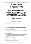
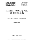
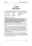
Revision 3.0 February. 2000
1
Model 3OOO
&
ACCESS 4000
SECURITY, ACCESS CONTROL &
BUILDING AUTOMATION SYSTEM
INSTALLATION MANUAL
OVERVIEW
The 3000/Access 4000 provides the next generation in Access Control, Security and Building Automation Systems.
MODULAR DESIGN & EXPANDABILITY Modular hardware design provides the ability to adapt and expand a system to cater
for virtually any configuration or application required - small or large. Large numbers of LCD Terminals, Input/Output Expanders
and Reader Modules can share a secure, monitored LAN system utilizing a fast, efficient communications format. Using the
recommended cabling, modules on the LAN can be installed hundreds of metres from the Control Module. Up to 250 modules can
be connected on the LAN system, comprising up to 99 modules of any particular type. With the current range of modules available,
this arrangement can provide over 3000 Zone inputs and over 3000 Auxiliaries on a single system.
THE MODULES. The heart of the system is the Control Module. This unit stores all data, communicates with all other modules
connected to the system LAN, and reports alarms and system activity to the Central Station. To program and operate the system an
Elite LCD Terminal is normally used. The LCD Terminal provides a 20 key backlit keypad, a backlit Liquid Crystal Display and
connections for several Zone Inputs and Auxiliary outputs.
Universal Zone Expanders are used to provide additional Inputs (16 or 32), Sirens and Auxiliaries (8 or 32) in a system and can be
installed remotely in suitable locations to greatly reduce the amount of cabling required to detectors and output devices. The Mini
Expander Module provides low cost expansion when up to 8 Zones and Auxiliaries are required along with special event counting
options (Event Counting available V3 or later).
Reader Modules are installed near the Door/s to provide Reader interfacing and up to 7 Inputs and 5 outputs for complete monitoring
and control of the Door/s.
The Analogue Module (using V3 or later Control Module firmware) allows analogue values to be monitored and set points used to
trigger control and/or report functions.
SYSTEM MANAGEMENT. PCDirect Upload/Download software is available for system Programming and Management, allowing
the option of local or remote connection with operator password protection. Windows based system management software is also
available incorporating dynamic graphics capabilities and sophisticated monitoring and report generation facilites.
MODEL 3000 / ACCESS 4000. Installation Notes.
2
Contents
CONTROL MODULE PARTS LIST ........................................................................................................................ 2
MOUNTING CONTROL MODULES AND EXPANDERS .................................................................................... 3
WIRING DIAGRAMS ............................................................................................................................................... 3-5
THE CONTROL MODULE PCB
Link Details ................................................................................................................................................................ 6
Wiring Terminal Details ............................................................................................................................................. 6
Header Connector Details ...........................................................................................................................................6
MENU FLOWCHART ............................................................................................................................................... 7
Control Module PCB layout ....................................................................................................................................... 8 & 9
Control Module Fault LED indications ...................................................................................................................... 9
Expander/Reader Module Fault LED indications ...................................................................................................... 9
LCD Terminal Error Messages .................................................................................................................................. 9
LAN SYSTEM OVERVIEW .....................................................................................................................................10
Connecting Modules to the LAN ...............................................................................................................................10 & 11
Cabling Details ........................................................................................................................................................... 12
System Earthing.......................................................................................................................................................... 12
System cabling configuration .....................................................................................................................................13
LAN Termination Details ...........................................................................................................................................13
Troubleshooting Flowchart ........................................................................................................................................ 14 & 15
LAN Voltage Testing .................................................................................................................................................16
Installing your Model 3000 / Access 4000 system.
Control Module Parts List
-
Control Module PCB mounted on metal sub-chassis in metal box.
Tamper switch bracket.
Telephone line cable.
Installation Kit containing:
- Plug pack.
- 7 x plastic “D” bungs.
- 7 x 8 Way plug-on screw terminals.
- Tamper switch.
- 2 x 6.3mm Tamper switch connectors.
- 2 x 4.8mm Battery terminal connectors.
- 1 x 2 Amp Fuse.
- 20 x 2k2 End-of-line resistors. (red-red-black-brown-brown)
- 20 x 6k8 End-of-line resistors. (blue-grey-black-brown-brown)
- Spiral bound User Manual.
- User’s Quick Reference Card. (4 page booklet)
- Installation Manual. (This document)
Disclaimer:
1. The manufacturer &/or it’s agents take no responsibility for any damage, financial loss or injury caused to
any equipment, property or persons resulting from the correct or incorrect use of the system or it’s peripherals. The purchaser
assumes all responsibility in the use of the system and it’s peripherals.
2. While every effort has been made to ensure the accuracy of this manual, the manufacturer assumes no responsibility or liability
for any errors or omissions. Due to ongoing development, this manual is subject to change without notice.
Revision 3.0 February. 2000
3
Mounting the Control Module & Zone Expanders
(Enclosure may vary - Australian enclosure illustrated)
n
The Control Module and Zone Expanders are supplied in metal boxes which must be secured to a flat, vertical surface
using fasteners through the four mounting holes in the chassis.
n
The tamper switch bracket must be positioned through the slot in the chassis, before the chassis is secured to the wall.
n
Orientation of the box MUST be as per one of the illustrations below.
n
Installation environment should be maintained at a temperature of
0º to 40º Celsius and 15% to 85% Relative humidity (non-condensing)
415mm
Depth=102mm
230mm
UP
12V, 6.5AH
Battery
Tamper switch
& bracket
Weight: 6.2kg (includes battery and cover)
Wiring Diagrams
ZONE INPUT WIRING
Typical Detection devices with Normally Closed Alarm contacts and Normally Closed OR Normally Open Tamper Contacts are
wired as follows:
N orm . C lo sed
T a m p e r C o n tac t
Z1
2 k2
6 k8
Z2
N o rm .
O pen
Ta m per
C on tac t
INPUT STATES:
N o rm .
C lo sed
A la rm
C on tac t
2k2
9k (2k2 + 6k8)
=
=
Open Circuit
Short Circuit
=
=
Sealed
Unsealed
(or Alarm)
Tamper
Tamper
Z3
Detection devices with Normally Open Alarm contacts are wired in exactly the same manner as above. When programming the
Zone Input, however, the option to “Reverse Seal and Alarm conditions” must be set to [Y]es.
e.g.
E01:Z01
Options ->
X S R A N T . .
n Y n n n n n n
MODEL 3000 / ACCESS 4000. Installation Notes.
4
SIREN WIRING
Maximum of two 8 Ohm Siren speakers may be connected to each siren driver, wired in parallel. Norm. Closed Siren cover
Tampers may be wired in series with the speaker cable. This method utilizes the siren speaker circuit monitoring.
AC +B -B S2 S1
Normally Closed
Siren cover tamper
CABLE: 14/0.2 Minimum
When wiring 2 speakers
in parallel it is best to
wire the cover tampers
to zone inputs & program
for tamper processing.
Normally Closed
Siren cover tampers
DIALLER LINE
Mode 3 socket wiring diagram for Dialler reporting formats. (e.g. IRfast and Contact ID)
Phone Line IN:
Pins 2 & 6
Phone Line OUT: Pins 1 & 5
1
2
3
4
604 Socket
to other equipment
3000/4000
Control
M odule
5
6
604 Plug from
3000/4000
1
2
Exchange
Line
1
JP101
2
3
4
3
4
5
6
5
6
604 Socket for
3000/4000 connection
DIRECT LINE
For Direct Line formats (e.g. EarthNet), the Leased Line connects to Pins 2 & 6.
3000/4000
Control
M odule
604 Plug from
3000/4000
1
2
Leased
Line
1
2
3
4
3
4
5
6
604 Socket for
3000/4000 connection
5
6
JP101
Revision 3.0 February. 2000
5
AUXILIARY WIRING
Rules for Auxiliary wiring on any module in the 3000/Access 4000 system.
- Aux’s 1 & 2 on Control & Expander Modules can switch up to 500mA continuous and are suitable for inductive loads.
(Except for Lock strikes, etc.)
- Max current on any other individual Auxiliary must be less than 200mA.
- On any module with Plug pack; Auxiliaries + LAN current + Detectors must be less than 700mA, or an external power supply
should be used.
- The Positive connection of the device must be wired back to the Positive connection nearest the Auxiliary. i.e. On the same
module.
- If an external power supply is used to power the device, a good common Negative connection MUST exist between the power
supply and the module.
- Clamp diode should be fitted across inductive loads. Kathode (bar) to +ve.
Locks are activated via a relay. External power supply is used for lock power to prevent voltage spikes reaching the Concept
equipment, provide longer battery backup & minimise the possibility of earth loops.
MODEL 3000 / ACCESS 4000. Installation Notes.
6
LINKS
LK2
RAM configuration. 1-2
2-3
2-3
LK3
Installer Code Default. Disconnect AC and Battery from Control Module; Short LK3 Pins; Reconnect power, then
remove the short. Installer code will be defaulted to “01”.
LK4
Continue. Used when required to rectify Memory problems.
CAUTION! Will erase all programming if shorted to initialise memory.
LK102/
LK103
32k DS1230Y (28 Pin)
128k DS1245Y (32 Pin)
512k DS1247Y (32 Pin)
Special. Only changed if advised by the Distributor.
LK104/
LK105
PSTN / Direct Line selection.
Both links 1-2
Direct Line (e.g. EarthNet)
Both links 2-3
PSTN (Dialler formats: IRfast, Contact ID, etc.)
LK201
Regulated Power Supply Current Limit setting.
No Link
1.0 Amp. Normal setting for Plug pack connection.
Link IN
1.5 Amp. Special custom external supply used.
LK202
LAN Termination. No Link. Unterminated. Link not fitted unless unit is first or last module on the LAN system.
Link IN. Terminated. Link fitted when unit IS the first or last module on the LAN system.
(See “LAN SYSTEM” details beginning on page 10 of this manual for more information)
TERMINALS
T205
POS
NEG
A
B
AX1
AX2
TAM
LAN connections.
(See “LAN SYSTEM” details in this manual
for more information)
Auxiliary output 1
Auxiliary output 2 (See “AUXILIARY WIRING” in this manual for wiring diagrams)
Terminals for connection of cabinet tamper switch. No End-of-line resistors necessary.
T206
Positive and Negative Detector Power connections. Note that total current drawn by devices connected to these
terminals, plus devices connected to Auxiliaries and the LAN power connections, must not exceed 700mA.
T207
AC
+B
-B
S1
S2
Terminals for 16Volt AC Plug pack connection. (supplied)
Plug pack specs:
Input:
240VAC RMS +/-5%.
Output:
16VAC RMS 1.5A
Positive connection to 12Volt 6.5 AH Battery.
Negative connection to 12 Volt 6.5 AH Battery.
“Internal” monitored Siren speaker connections. See “SIREN WIRING” on p4 for wiring diagrams.
“External” monitored Siren speaker connections. See “SIREN WIRING” on p4 for wiring diagrams.
HEADERS
JP1
Port 0 connection. Using the “Port 0 Interface cable” (IRU3000), allows temporary connection of a PC for Upload/
Download programming. This Port shares the on-board modem with the Line interface and therefore MUST NOT be
used as a permanent connection.
JP2
Header for connection of IRPX3000 UART Port Board. A UART Board and appropriate cable/s must be fitted if
Printer, PC, External Modem or
Securitel Interface etc. is being used. When fitting the UART board, disconnect
and battery from the Control module and align the connectors carefully.
power
Revision 3.0 February. 2000
3000 / ACCESS 4000
Menu Flowchart
7
MODEL 3000 / ACCESS 4000. Installation Notes.
8
THE CONTROL MODULE PCB
LK3 Installer
Code Default
LK4 “Continue”
Caution. See
notes.
JP2 Expansion Port
UART Interface connection.
JP101
Mode 3 Line Socket for
connection to Telecom
Line. (Cable supplied)
See “DIALLER LINE” on
p4 for wiring diagram
LK104
LK105
PSTN
Direct Line
LK4
LK3
Both 2-3.
Both 1-2.
LK201
Regulated P.S. Current Limit
No Link
Plug pack
(normal-1.0Amp)
Link IN
1.5Amps
(Custom Ext. Power
supply only)
LK202
T207 Power Supply & Sirens
AC
B+/BS1
S2
JP1 Port 0
See notes
Plug pack connections.
(See Notes)
12V 6.5AH Battery.
Internal Siren output
External Siren output
LK202 LAN Termination.
No Link
Link IN
Unterminated
Terminated. (Only if module
is at either end of the LAN)
LAN Activity
LEDs
Rx =Receive Data
Tx =Send Data
T205 LAN, Auxiliary
outputs & Cabinet Tamper
input. See Notes.
Revision 3.0 February. 2000
9
CONTROL MODULE FAULT LEDs
LED1
ON
T201 to T204. Zone Inputs.
See “ZONE INPUT WIRING”
on p3 for details.
JUMPER LINK
ORIENTATION
1
2
3
•
•
•
1 2 3
• • •
LED2
OFF
EXPLANATION / REMEDY
Ram Fault. RAM faulty, in backwards, out by one pin or
LK2 not correct. Power off, fit correctly or replace.
OFF
ON
Non-volatile RAM not initialised. Short LK4 to continue.
(Erases all programming)
ON
ON
Configuration Problem. Return options memory chip to
Distributor.
Fast Flash OFF
Hardware Problem. (EEPROM) Return unit for service.
OFF
Fast Flash Wrong GAL for NVRAM size. (Illegal Memory size)
Contact the Distributor.
Fast Flash Fast Flash Wrong GAL for required options. (Illegal option/s)
Contact the Distributor.
Fast Flash ON
Faulty Program chip. (EPROM) Return unit for service.
ON
Fast Flash No default for installer code. Short LK4 to continue.
Contact Owner/Master Code holder.
Slow Flash Slow Flash Secure Micro Version wrong. Contact the Distributor.
Slow Flash ON
Lock bits not set. Contact the Distributor.
LK2 RAM Configuration
2-3 32k DS1230Y (28 Pin)
1-2 128k DS1245Y (32 Pin)
1-2 512k DS1247Y (32 Pin)
Note orientation and position of
28 Pin IC in bottom of socket.
JP3 Auxiliary
Expander Header
connection for
IRA3000 8 Auxiliary
Expander.
CONTROL MODULE
FAULT LED
DIAGNOSTICS
See table on this page.
EXPANDER / READER MODULE FAULT LEDs
RX
ON
OFF
TX
ON
ON
Flash
ON
Flash
Flash
ON
OFF
LCD TERMINAL ERROR MESSAGES
MESSAGE
No Rx
Can’t Tx
Exists
T206
Detector Power
connections.
EXPLANATION / REMEDY
Module is un-addressed.
Module type unknown. Firmware upgrade required to
Control Module.
Duplicate Module. This module number is already in use
by a module of the same type.
Module number selected is too big for Control Module
RAM size. Select a lower Module number.
Too many modules on Network for Control Module RAM
size.
Too Big
Too Many
EXPLANATION / REMEDY
Terminal requesting address from Control Module, but no
reply being received.
Terminal cannot send data because LAN is being held in
“start” condition. Check for A/B reversed.
Module number selected already being used by another
LCD Terminal. Choose another number.
Module number selected is too big for Control Module
RAM size. Select a lower Module number.
Too many modules on Network for Control Module RAM
size.
MODEL 3000 / ACCESS 4000. Installation Notes.
10
LAN SYSTEM OVERVIEW
The 3000/Access 4000 LAN (Local Area Network) is a 3 or 4 wire network used to connect the modules in a system.
Up to 250 modules can be connected on the LAN system, comprising up to 99 modules of any particular type. Using the recommended
cable types, modules on the LAN can be installed many hundreds of metres from the Control Module.
Data encryption ensures secure LAN communications at all times, while the programmable supervisory polling system continuously
monitors the network to detect cable tamper, cable fault conditions, module off-line and module substitution. The data format used
in the 3000/Access 4000 LAN has been developed to ensure fast, reliable communications regardless of the size of the system.
For larger systems and complex sites, LAN Isolators are used to provide opto-isolation between sections of the LAN, eliminate
potential earth loop problems, improve surge and lightning protection, provide signal level restoral for improved performance over
longer cabling distances and offer a monitored “loop” LAN wiring option for a higher level of LAN integrity.
CONNECTING MODULES TO THE LAN. Refer to diagram opposite.
- “A” & “B” signal connections are wired in parallel across the system using twisted pair cable.
See “Cable Types” details on page 12.
The “NEG” connection (0V reference) must also be wired to every module. ·
¶
- An optional + 12 V connection (LAN +ve) may be used to provide power to modules that do not have their own Plug pack
and on-board power supply. e.g. LCD Terminals. ¸
- The + 12 V connection (LAN +ve) used to power LCD Terminals, etc. can be derived from any module with it’s own Plug
pack and on-board power supply (Control Module and Expander Modules), or from a separate external power supply. ¹
CAUTION ! Never connect the +ve (POS) of two power supply sources together. i.e. Control Module LAN POS, Expander
Module LAN POS, or External Power Supply +ve. This is one of the reasons that “SPARE” wiring terminals are provided on
most types of modules.
- When wiring the LAN to modules that are powered from their own Plug pack (e.g. Zone Expanders), use the “Spare” terminal
(labelled “SPARE” or “SPR”) for the LAN +ve connection. º
NOTE: LAN “POS” and “NEG” should not be used to power detectors, relays, etc. Always use “DET+” and “DET-” on the
module to power these devices.
- When wiring the LAN to modules that are powered from an external Power Supply (e.g. Reader Modules), use the “Spare”
terminal (labelled “SPARE” or “SPR”) for the LAN +ve connection. »
- A DC Voltmeter may be used to check that the LAN will operate reliably. See “LAN Voltage Testing” on Page 16.
Revision 3.0 February. 2000
11
Connecting Modules to the LAN.
TAM
TAM
AX2
AX1
B
A
NEG
POS
EXPANDER
MODULE
- LAN +ve
wired to
“SPR” (Spare).
- “POS” used
as LAN +ve
supply source.
EXTERNAL
+12V
POWER
-VE
SUPPLY
TAMPER
GND
EXT PWR
SPARE
B
A
GND
+VE
»
READER
MODULE
- Powered
from external
Power supply
(LAN “+ve”
connected to
“SPARE”)
TAMPR
GND
EXT PWR
SPARE
B
A
GND
+VE
READER
MODULE
- Powered
from LAN.
¹
º
POS
NEG
A
B
SPR
SPR
TAM
TAM
EXPANDER
MODULE
- LAN “+ve”
wired to
“SPR” (Spare).
POS
NEG
A
B
SPR
SPR
TAM
TAM
·
¸
¶
º
¹
LAN B
LAN A
GND
+VE
X01
X02
X03/Z01
X04/Z02
CONTROL
MODULE
ELITE LCD
TERMINAL
MODEL 3000 / ACCESS 4000. Installation Notes.
12
CABLE TYPES
- TWISTED PAIR Cable MUST be used to connect the LAN.
Two pair Telephone or LAN cable is suitable as it provides all 4 conductors required. One twisted pair for “A” & “B”, and
the other for “POS” & “NEG”. Unshielded cable is quite acceptable, however, in situations where electrical storms or high
levels of electrical interference are a problem, shielded 2 pair cable may be used. Examples of suitable 2 pair cables:
Unshielded. Figure 1.
Shielded (All Multistrand) Figure 2.
Olex TJC590AA002
Olex JEIP87AA002
Belden 8723 *
† 3 Pair.
Tycab TIC6105 †
Tycab DPF4702
Tycab DQQ47025 *
‡ Multistrand (7/0.2).
MM MegaTwistpatch ‡
MM B2002CS
Garland MCP-2S
* Indivually screened pairs.
- If SHIELDED CABLE is used, DO NOT use the shield as a negative connection & do not allow the shield to make contact
with Negative, Ground, or any other wiring or metalwork within the system. Shields should only be terminated to a
Protective Earth at ONE END of the cable. ¶ See “System Earthing” below. If no suitable earth point is available at a
module location, the shield can be looped back to the shield of the previous length of cable. ·
- LAN POWER CABLING. Separate heavy duty Figure 8 cable ( 24 / 0.20 recommended) should also be run for “POS” &
“NEG” over longer distances if used for powering modules. e.g. LCD Terminals. Figure 3.
LAN “POS” current required:
Max. Cabling Length for LAN +ve (POS) & GND (NEG)
Twisted pair
Fig 8. 14 / 0.20
Fig 8. 24 / 0.20
60mA (e.g. 1 LCD Terminal)
200 metres
400m
640m
120mA (e.g. 2 LCD Terminals)
100 metres
200m
320m
180mA (e.g. 1 Reader Module - Reader pwr not incl) 62metres
130m
210m
250mA (e.g. 4 LCD Terminals)
50 metres
100m
160m
500mA (e.g. 8 LCD Terminals)
25 metres
50m
76m
Remember to allow for any extra current required by Detectors, Auxiliaries, Readers, etc:
NOTE: Lock strikes must not be powered from the LAN.
Relay (1A contacts)
approx. 25mA
Small Proximity reader (~10cm read range) ~50 to 120mA
Relay (5A contacts)
approx. 45mA
Standard Prox reader (~15cm read range)
~120 to 180mA
PIR
15 to 25mA typical.
Magnetic Swipe reader.
~15mA
Figure 1.
Twisted pair communications cable.
Figure 2.
Shielded, twisted pair
communications cable
Figure 3.
Heavy duty Figure 8 cable. 24 / 0.20
Used for LAN +ve & GND on long cable
runs.
SYSTEM EARTHING
- DO NOT CONNECT A SYSTEM TO EARTH. This includes all Modules, Input, & Output devices. Plug packs do not have
an earth wire as earthing is not required. Also ensure that mounting screws etc., or peripherals connected to modules do not
provide an earth connection to the module. This is to avoid earth loops occuring.
- A Printer, PC, modem, etc. connected to the Control Module may provide a connection to earth via the Serial cable. This is
acceptable but is the only exception to the above rule.
- LIGHTNING PROTECTION. In multi-building installations and on longer cable runs, shielded cable may be used to provide
added protection against lightning strike. Each individual shield should be terminated to a Protective Earth point such as an
earth stake, building earth (metal building framework) or water pipe. ¶ It is very important to ensure that the shield
makes no contact with Negative, Ground or any other wiring within the system.
LAN Isolator/s can also be included in a Lightning protection scheme to electrically isolate different sections of the LAN at
the point where LAN cabling enters/exits each building, or on cable runs that are more exposed to lightning strike.
Revision 3.0 February. 2000
13
SYSTEM CABLING CONFIGURATION Figure 4 & Figure 5.
- Avoid installing the LAN cable with mains power cables & any other cables likely to cause interference wherever possible
- No module is to be more than 1.5km (1500 metres) cable length from the Control Module OR from a LAN Isolator
“LAN 2” or “LAN 3” Port. ¸ (LAN Isolator/s can be used to extend the maximum cabling distance)
- TOTAL LAN CABLING in a system without LAN Isolators should not exceed 2000 metres, and/or 64 Modules. ¹
If the total amount of LAN cable will exceed 2000 metres, and/or there are more than 64 modules to be connected, LAN
Isolator/s must be used to separate the LAN system into sections and maintain optimum LAN performance. i.e. Include one
LAN Isolator for every 2000 metres of LAN cabling and/or for every 64 Modules connected. º
LAN TERMINATION Figure 4 & Figure 5.
- The LAN MUST be Terminated for optimum performance, by ensuring that the Termination Resistor (470 Ohm*) is “IN” on
the first and last modules in the LAN network. Terminated modules are indicated with a “T” on the illustrations. »
(Termination is put “IN” with a jumper link or a DIPswitch, depending on the module type) * See Note 1 on Page 15.
- MULTIPLE CABLE RUNS. In systems where there are multiple cabling runs going out from the Control Module or LAN
Isolator (i.e. “star” configuration), Termination is fitted on the modules at the end of the two longest runs. ¼
Figure 4.
Simple LAN configuration.
¹
LCD
TERMINAL
2000 metres max.
READER
MODULE
·
»T
»
¶
¸
1500 metres max.
EXPANDER
MODULE
LCD
TERMINAL
CONTROL
MODULE
T
Figure 5.
Complex LAN configuration.
LCD
TERMINAL
EXPANDER
MODULE
CONTROL
MODULE
»
T
5 m.
400 m.
300 m.
500 m.
350 m.
LCD
TERMINAL
º
600 m.
READER
MODULE
¼
T
»
T
LAN1
READER
MODULE
LCD
TERMINAL
LAN Isolator
LAN2
LCD
TERMINAL
100 m.
LCD
TERMINAL
READER
MODULE
150 m.
LCD
TERMINAL
LAN3
T
» 600 m.
500 m.
EXPANDER
MODULE
¼
T
500 m.
¸
1500m.
from
“LAN3”
400 m.
300 m.
¹ Total LAN cable in this section < 2000m (1955 m)
READER
MODULE
»
T
MODEL 3000 / ACCESS 4000. Installation Notes.
14
LAN TROUBLESHOOTING FLOWCHART
BEFORE SYSTEM POWER UP
(No Power connected to modules
AND No batteries connected)
A1. WHERE POSSIBLE, PHYSICALLY CHECK:
-LAN A & B connections not reversed on any module.
-No modules connected to earth. (via mounting bolts, ext.
power supplies, input/output cabling, etc.) Note that the
Control Module may be connected to earth via external
equipment connections. i.e. Printer, PC, modem, etc. If
so, this must be the only earth connection in the system.
-Only two modules in the system are terminated.
⇓
A2. CHECK FOR SHORT CIRCUITS ON THE LAN
(No Power connected AND No batteries connected)
METER ON OHMS RANGE
Check at the Control Module for short circuits between:
-LAN A & B.
-LAN A to +ve and -ve.
-LAN B to +ve and -ve.
Note:DC Resistance in the LAN cable (~0.18Ohms/metre)
can mask short circuits that exist on longer cable runs.
⇓
A3. CHECK FOR CORRECT LAN TERMINATION
(No Power connected AND No batteries connected)
METER ON OHMS RANGE
Measure between LAN A & LAN B on the Control
Module:
170 to 300 Ohm.* OK. (System with up to 32 modules)
140 to 270 Ohm.* OK. (System with up to 64 modules)
Lower value.
More than two modules terminated
or Short cct across LAN A & LAN B.
Higher value. Less than two modules terminated
or Open cct on LAN A &/or B wiring.
* See Notes 1 & 2.
⇓
POWER UP SYSTEM & CONNECT BATTERIES
⇓
A5. DETERMINE THE TYPE OF LAN PROBLEM
A. SOME MODULES HAVE INTERMITTENT
COMMUNICATIONS PROBLEM.
Proceed to Step B1, “Intermittent LAN problems”.
⇒
B. SOME/ALL MODULES NOT COMMUNICATING
AT ALL. Proceed to Step A6.
⇓
A6. IS THE LAN COMPLETELY DEAD ?
YES. Proceed to Step C1, “LAN Dead”.
⇒
⇒
NO. (Some Modules not communicating, others OK)
Proceed to Step A7.
⇓
A7. CHECK STATUS OF PROBLEM MODULE/S
DC POWER CHECK. Meter on DC Volts range. Check for
11 to 14 Volts between LAN +VE & LAN -VE (GND) on
the problem module. See Note 3.
Check FAULT LEDs (TX & RX LEDs) OR LCD Display
on problem Module:
Both LEDs Off OR Display has no “Module ...” messages.
Proceed to step A8.
Any other state. Refer to “Expander/Reader Module Fault
LEDs” table or “LCD Terminal Error messages” table
on Page 9.
⇓
A8. TEST LAN VOLTAGES AT PROBLEM MODULE/S
Perform LAN Voltage Checks at the problem Module/s.
Refer to the table “LAN Voltage Testing” on Page 16.
A4. CHECK CONTROL MODULE OPERATION
DC POWER CHECK. With Meter on DC Volts range,
measure between LAN +VE & LAN -VE (GND) on the
Control Module:
11V to 14V.
OK.
<11V.
Too many devices being powered from
the Control Module or Battery Flat.
Check FAULT LEDs on Control Module:
Both Off.
OK. Proceed to step A5.
Any other state. Refer to “Control Module Fault LEDs”
table on Page 9.
⇓
A9. SUBSTITUTE MODULE/S
If the troubleshooting procedure fails to locate any power,
wiring or termination problems, you may have an
equipment fault. Replace the module/s suspected of
causing the problem.
Revision 3.0 February. 2000
15
INTERMITTENT LAN PROBLEMS
⇒
⇒
⇒
⇒
⇒
B1. WHICH MODULES ARE INTERMITTENT ?
Using an LCD Terminal or Review Logging via Upload/
Download software, check Review Data for “Module Lost”
and “Module Found” messages.
Each message will also identify the Module type and
number. Note the problem module/s.
Proceed to Step B2.
LAN DEAD
⇒ C1.
⇓
TEST VOLTAGES AT CONTROL MODULE
Perform LAN Voltage Checks at the Control Module.
Refer to the table “LAN Voltage Testing” on Page 16.
B2. IS ANOTHER EVENT CAUSING THE MODULE
TO
BE LOST ?
If this fails to locate the problem, proceed to Step C2.
Look at the Review Messages immediately preceding the
“Module Lost” messages for any event that repeatedly
coincides with the loss of module/s, or if the loss of
module/s occurs at, or around, the same time of day.
Look for messages such as Door Un-lock/Lock, Siren On,
Auxiliary On, etc., and note the times when the “Module
Lost” messages occured.
⇓
C2. ISOLATE PROBLEM CABLING OR MODULE/S
Disconnect all LAN wiring from Control Module.
Reconnect one LCD Terminal and ensure that it
communicates. (If it doesn’t, follow Steps A7 & A8)
YES. Ancillary devices & external equipment (e.g.
electrical machinery) can produce voltage spikes, electrical
noise and excessive current drain.
If the LAN, Power & Auxiliary circuits are not wired
correctly or Earth loops exist, these devices can interfere
with LAN communications.
Reconnect the LAN one module at a time until a problem
module, or section of cabling kills LAN communications
when reconnected.
With the problem area identified, proceed to Step A8.
If such an event does coincide with loss of comms,
reproduce the sequence of events to confirm the effect, then
check any associated wiring circuits accordingly.
⇓
⇐
⇐
⇐
⇐
⇐
⇐
NO. Proceed to Step A8
NOTES:
1. LAN TERMINATION CHECK
Very early 3000 products (Australia & NZ only) had 120
Ohm Termination resistors which results in lower
measurements (~70 to 140 Ohms). When expanding these
systems, take termination OUT on the existing modules,
and put termination IN on two of the new modules.
Alternatively, take termination OUT on the existing
modules and fit a 470 Ohm resistor between LAN A & B
on those two modules instead. NOTE: This is only
necessary if expanding the system, or if there are
communication problems. If the system is operating
reliably, no modification is necessary.
2. TERMINATION RESISTOR CHECK
To determine if a module is fitted with a 120 Ohm or 470
Ohm Termination Resistor, ensure that TERM is “IN”,
disconnect the module from the LAN, remove power, and
measure across LAN A and B on the module with the
meter on the OHMS range.
3. MODULE POWER TEST
The Test Menu can be used to check LAN Power
conditions. Logon to the LCD Terminal, then press
<MENU>, 4, 8. This activates the power test, and the
results will be displayed on the LCD Terminal, and in the
review memory. See “Concept 3000 Programmer’s
manual” Rev 2.3 p154 for more information.
MODEL 3000 / ACCESS 4000. Installation Notes.
16
LAN VOLTAGE TESTING
NOTES:
1. These Voltage checks should be done with no (or minimal) communications traffic on the LAN. To ensure this:
a) Check that poll times for all addressed modules in the system are set to the default 60 / 120 seconds or greater.
b) Disconnect LAN A and LAN B from any unaddressed modules on the LAN, as these modules will be constantly
attempting to send messages to the Control Module.
c) Ensure that Terminals, Readers, etc. are not being used while performing tests.
Before proceeding with Voltage tests, check the “RX” LED on the Control Module to confirm that there is minimal LAN
activity.
2. To determine if a problem exists on the module under test, or elsewhere on the LAN, these voltage tests can be performed:
a) With the module connected to the LAN.
b) On the cable connections with the module disconnected from the LAN.
Te s t Point
+ PROBE
LAN +ve
LAN B
Te s t Point
- PROBE
LAN - ve or GND
LAN A
EXPECTED
RESULT
PROBLEM /
REM EDY
11V to 14V DC
0V. Open circuit LAN +ve connection, or short cct between
LAN +ve and LAN - ve.
<11V. Too many modules powered from the LAN power
supply source.
Length (or guage) of LAN cabling causing excessive Voltage
drop on the cable.
200 to 400mV DC
<200mV. Short cct between LAN A & B.
More than 2 modules terminated in this section of LAN.
>400mV. LAN A &/or LAN B Open circuit.
Less than 2 modules terminated in this section of LAN
<0V (Ne gative re ading). LAN A & LAN B connections
reversed.
LAN A
LAN - ve or GND
200mV to 2.5V DC
<200mV / >2.5V DC. System may have more than one
module connected to an earth point, causing earth loop/s.
Ensure that no more than one module in the system is connected
to earth. Remember that a module may be connected to earth
via a peripheral device or it's cabling. e.g. PC, Printer, External
power supply, Detector, Output device, etc.
If installation methods &/or system configuration makes multiple
earth points unavoidable, install LAN Isolator/s at suitable points
in the LAN system to isolate the earthed section/s
LAN B
LAN - ve or GND
200mV to 2.5V DC
As above.
Designed & manufactured in Australia.
©
2000. Inner Range Pty. Ltd.
Part No: 630023