1
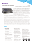
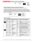
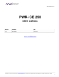
PWR-DSP3 User Manual
PWR-DSP3
DSP processed Plate Amplifier
User Manual
Version 1.0
Revision
Description
Date
V1.0
User manual – Initial version
01-06-2011
Page 1 of 27
Copyrights DSP4YOU ltd
PWR-DSP3 User Manual
PRODUCT DESCRIPTION
The PWR-DSP3 answers the needs for a high power yet high quality plate amplifier module. Based on the synergetic
and innovative technology from DSP4YOU and PASCAL Audio, the module is a turnkey solution for multi-way
powered speakers. Third generation Class-D amplification, Digital Signal Processing (DSP) and the Audio Video
Bridging (AVB) are just examples of the embedded technology of this breakthrough product. With an impressive
maximum rating of 2400W (ch1) and 700W (ch2&3), be sure to find no compromise on audio quality from studio/ Hifi
systems to Pro-A/V applications.
Last but not least, the optional Audio Video Bridging (AVB) allows streaming of multiple uncompressed, low latency
and synchronized audio channels over Ethernet networks. Extended cable length, noise immunity and flexible routing
are some of the many obvious advantages of AVB. With our live amplifier health monitoring (load, temperature, clip),
live changes of the DSP settings and ZeroConf support, the PWR-DSP3 is a true Plug&Play device easily configured
over Ethernet or Wifi networks: A setup summarized by three words: Plug, discover, control.
Features
* Ultra high power module
* Latest AVB & DSP technology
* OEM friendly
Power Amplifier
Control
* Third generation class D technology
* Up to 2400W on channel 1
* Up to 700W on channel 2 and 3
* Self protection & power hibernation
* Regulated SMPS for 85 ~ 268V operation
* ZeroConf for Plug&Play configuration
* Remote control for up to 256 amplifiers
* DHCP or Link Local Addressing (Auto IP)
* Remote firmware upgrade over network
Audio Video Bridging (Optional)
Flexible Digital Signal Processor
* Low latency, synchronized streaming
* Up to 3 incoming streams
* Redundant network connectivity
* Crossover (Up to 48dB/oct)
* Equalization (PEQ / Shelf)
* Compressor/Limiter
* Time alignment / phase / gain control
* Audio, Power, clip and thermal metering
SYSTEM DIAGRAM
Page 2 of 27
Copyrights DSP4YOU ltd
PWR-DSP3 User Manual
Table of Content
1
2
Safety Instructions ......................................................................................................................................................................4
Product Overview......................................................................................................................................................................6
2.1
Front Panel Description – Top section ..........................................................................................................................6
2.2
Front Panel Description – Bottom section....................................................................................................................7
2.3
Rear panel description ...................................................................................................................................................7
2.4
Feature description .........................................................................................................................................................8
2.4.1
PWR-DSP3 Amplifier specifications.........................................................................................................................8
2.4.2
Digital Signal Processing (DSP)................................................................................................................................9
2.4.3
Audio Video Bridging (AVB)..................................................................................................................................10
3
Setup guide ..............................................................................................................................................................................11
3.1
Box content ....................................................................................................................................................................11
3.2
Mounting instructions ....................................................................................................................................................11
3.2.1
Mechanical installation of PWR-DSP3..................................................................................................................11
3.2.2
Thermal consideration ...........................................................................................................................................11
3.3
Connectivity...................................................................................................................................................................12
3.3.1
Network ....................................................................................................................................................................12
3.3.2
Analog audio connectivity ...................................................................................................................................12
3.4
Step by Step guide........................................................................................................................................................13
3.5
AVB Streamer Tools setup guide .................................................................................................................................13
4
System Configuration..............................................................................................................................................................14
4.1
User interface overview................................................................................................................................................14
4.2
PWR-DSP3 configuration ..............................................................................................................................................14
4.2.1
Device Tree..............................................................................................................................................................14
4.2.2
Device info Tab .......................................................................................................................................................15
4.2.3
Audio settings Tab ..................................................................................................................................................16
4.2.4
Audio Video Bridging (AVB) stream configuration............................................................................................19
4.2.5
System Settings Tab ................................................................................................................................................21
5
Technical specifications .........................................................................................................................................................23
5.1
Electrical specifications................................................................................................................................................23
5.2
Absolute maximum rating............................................................................................................................................24
5.3
Typical amplifier electrical specifications .................................................................................................................24
5.4
Thermal specifications ..................................................................................................................................................24
5.5
Mechanical drawings...................................................................................................................................................25
5.6
Product Warranty Terms and conditions ...................................................................................................................27
Page 3 of 27
Copyrights DSP4YOU ltd
PWR-DSP3 User Manual
1
Safety Instructions
• Read the information for use
• Please keep this user manual in a safe place during the lifetime of the product. The user manual forms an integral
part of the product. Reselling of the product is only possible if the user manual is available. Any changes made to the
product have to be documented in writing and passed on to the buyer in the event of resale.
• Heed all warnings.
• Follow all instructions.
• Do not use this product near water (for example, in damp rooms or near a swimming pool).
• Clean only with dry cloth.
• Do not cover the heat sink. Install in accordance with the user manual.
• Do not install near any heat sources such as radiators, heat registers, stoves, or other apparatus that produce heat.
• Protect the power cord from being walked on, pinched or damaged in any other way. Pay particular attention to
plugs and the point where they exit from the Amplifier Unit.
• The product may only be used in accordance with the information provided in the user manual. Before and during
the usage of the amplifier please ensure that all recommendations, especially the safety recommendations as
detailed in the user manual, are adhered to. The Amplifier Unit is designed for the amplification of pulsed audio
signals and the Amplifier Unit should only be connected to speakers with average impedance that is not lower than
the impedances specified in the User's Manual.
• Do not place the product on an unstable cart, stand, tripod, bracket, or table. The device may fall, causing serious
injury, and serious damage to the device itself.
• The Amplifier Unit can only be disconnected from the power supply by removing the plug, which must be freely
accessible at all times. Unplug this Amplifier Unit during lightning storms or when unused for long periods of time.
• Refer all servicing to qualified service personnel.
Damages that require service
Unplug the Amplifier Unit from the mains supply and refer to your dealer/distributor or other authorized repair
workshop. Servicing is required when
1. The power-supply cord or plug has been damaged,
2. Liquid has been spilled or objects have fallen into the amplifier,
3. The amplifier has been exposed to rain or moisture,
4. The amplifier has been dropped or suffered damage in any other way,
5. The amplifier exhibits a distinct change from its normal function or performance.
Servicing
Do not attempt to service this product yourself. As opening or removing covers may expose you to dangerous
voltage or other hazards, the amplifier may only be opened by qualified personnel. Please refer to your
dealer/distributor.
Servicing and Replacement Parts
All service and repair work must be carried out by an authorized dealer/distributor. When replacement parts are
required, please ensure that the dealer/distributor only uses replacement parts specified by the manufacturer. The
use of unauthorized replacement parts may result in injury and/or damage through fire or electric shock or other
electricity-related hazards.
Safety Check
Upon completion of any service or repairs to this product, ask the dealer/distributor to perform safety checks to
determine that the amplifier is in proper operating condition.
Read the information for use (user manual)
When shipping the product, always use the original shipping carton and packing materials. For maximum protection,
repack the unit as it was originally packed at the factory.
Environments
Use this product only in E1, E2, E3 or E4 environments according to EN55103-2 “Electromagnetic compatibility –
Product family standard for audio, video and audio-visual and entertainment lighting control apparatus for
professional use – Part 2: Immunity”
Ventilation and heat sink
The heat sink is provided to ensure reliable operation of the Amplifier Unit and to protect it from overheating. The
heat sink must not be blocked or covered. This product should not be installed unless proper ventilation is provided or
manufacturer’s instructions have been adhered to.
Water And Moisture
Do not use this product near water (for example, in damp rooms or near a swimming pool).
Page 4 of 27
Copyrights DSP4YOU ltd
PWR-DSP3 User Manual
Cleaning
Unplug the Amplifier Unit from the wall outlet before cleaning. Do not use liquid or aerosol cleaners.
Power-cord Protection
Power supply cords should be routed so that they are not likely to be walked on or pinched by items placed upon
them or against them, paying particular attention to cords and plugs, and the point where they exit from the
Amplifier Unit.
Lightning
For added protection of the product during lightning storms, or when it is left unattended and unused for long periods
of time, unplug it from the wall outlet. This will prevent damage to the product due to lightning and power-line surges.
Disconnection from the mains power supply can only be achieved by removing the plug from the mains socket and
by external disconnection of all poles from the mains.
Interference of external objects and/or liquids with the appliance
Never push objects of any kind into this product through openings as they may touch dangerous voltage points or
short out parts that could result in a fire or electric shock. Never spill liquid of any kind on the amplifier.
Accessories
Do not place this product on an unstable cart, stand, tripod, bracket, or table. The product may fall, causing serious
injury, and serious damage to the product. Any mounting of the product should follow the manufacturer’s instructions,
and should use a mounting accessory recommended by the manufacturer.
Connecting
When you connect the Amplifier Unit to other equipment, turn off the power and unplug all of the equipment from
the supply source. Failure to do so may cause an electric shock and serious personal injury. Read the user's manual of
the other equipment carefully and follow the instructions when making the connections.
Sound Volume
Reduce the volume to minimum before you turn on the amplifier to prevent sudden high levels of noise which may
cause hearing or speaker damage.
Output connectors
WARNING: Output connector marked with the lightning flashes indicate high voltages that are potentially
life threatening. Wiring to these terminals requires installation by an instructed person and the use of readymade leads or cords. Custom wiring should only be carried out by qualified personnel.
To prevent electric shock, do not operate the product with any of the conductor portion of the speaker wire
exposed.
NOTE: For reasons of safety and performance, use only high-quality fully insulated speaker cables of stranded copper
wire. Use the largest wire size that is economically and physically practical, and make sure the cables are no longer
than necessary.
Precautions when connecting to MAINS IN and MAINS LINK
When mounting or connecting the product always disconnect it from mains. Only connect the product to an
appropriate AC circuit and outlet, according to the requirements indicated on the rating plate.
If a power cut occurs while the amplifier is switched on, it will restart automatically once the power supply has been
restored. All settings prior to the loss of power will be maintained.
IMPORTANT: Always connect the Product to mains through the MAINS IN connector on the Amplifier Unit.
IMPORTANT: Always use ready-made mains cables with original POWERCON connectors when connecting the
product to mains.
IMPORTANT: When disconnecting the Product from the mains, always disconnect at the mains end first, before
disconnecting the powerCon connector at the Product end.
IMPORTANT: Only connect additional Products to the MAINS LINK connector keeping within the specified power
rating. Always use ready-made mains link cables with original POWERCON connectors.
DO NOT REMOVE MAINS CONNECTOR GROUND, IT IS ILLEGAL AND DANGEROUS.
Page 5 of 27
Copyrights DSP4YOU ltd
PWR-DSP3 User Manual
2
2.1
Product Overview
Front Panel Description – Top section
2
1
6
5
6
3
4
1. LINK OUT analog output for channel linking out from input channel 1.
2. ANALOG INPUTS channel 1&2. Fully balanced input with Pin1 (shield), Pin2 (+), Pin3 (-)
3. XLR/AVB SOURCE SWITCH for momentary source selection between the analog and the network (AVB) source
o
LED ON to indicate when module is using the XLR input
o
LED OFF to indicate when module is using the AVB input
This source selection can also be controlled from the user interface of the software.
4. NETWORK CONNECTOR on Neutrik Ethercon connectors. For Control and Ethernet audio streaming (AVB)
5. MASTER VOLUME control on rotary potentiometer.
6. LED INDICATION for status indication:
o
Power: ON to indicate when module is powered ON.
o
Thermal: ON to indicate when module is in Thermal protection
o
Network: ON to indicate when module is connected to the network
o
Clip 1 to 3: ON to indicate when the amplifier output clips
Page 6 of 27
Copyrights DSP4YOU ltd
PWR-DSP3 User Manual
2.2
Front Panel Description – Bottom section
2
2
1. MAIN AC IN on PowerCON 20AMP connector (NAC3FCA). Universal 95~240V power supply input
2. LINK OUT on PowerCON 20AMP connector (NAC3FCB) for linking to another amplifier within limits of your AC circuit.
The powerCON is a locking 3 conductor equipment AC connector with contacts for line, neutral and pre-mating
ground contact. It replaces appliance couplers wherever a very rugged solution in combination with a locking
device is needed in order to guarantee a safe power connection. Connector is to be purchased separately.
Attention: The powerCON is a connector without breaking capacity, i.e. the powerCON should not be connected or
disconnected under load or live!
For more information, please consult the Neutrik website:
Product page
Product specifications
Assembly instructions
-
2.3
Rear panel description
The amplifier outputs are provided on 3 x MOLEX connectors, 6.3mm pitch as shown on picture below. Female
connectors are flush mounted to the enclosure of the PWR-DSP3. Three male connectors along with 6 inserts are
provided as part of the product.
WARNING: Output connector marked with the lightning flashes indicate high voltages that are potentially
life threatening. Wiring to these terminals requires installation by an instructed person and the use of readymade leads or cords. Custom wiring should only be carried out by qualified personnel.
Page 7 of 27
Copyrights DSP4YOU ltd
PWR-DSP3 User Manual
2.4
2.4.1
Feature description
PWR-DSP3 Amplifier specifications
The PWR-DSP3 is an amplifier with total of 2400W limit by its power supply. The following electrical specifications show
the typical operating
Thermal specifications
NOTE: Channel 2 and 3 of the amplifier are single Ended amplifier designs which can pump back energy on the
power supply. At low frequencies this can cause asymmetrical power supply voltage rails, resulting in premature
clipping of the amplifier outputs or over-voltage protection of the power supply. When channel 2 and 3 are used to
amplify low frequency signals E.G with monitors, please take following actions.
Input for channel 2 should be inverted inside the DSP. This will cancel the supply pumping between channel 2 and 3.
In order to have outputs of channel 2 and channel 3 in phase, the output of channel 2 should be phase inverted by
interchanging the + and – connections for the speaker. Please see drawing below.
CH1
CH2
Phase
inverted
Page 8 of 27
Speaker all in
phase and no
energy pumped
back to PSU
CH3
DSP
Configuration
Speaker
connectivity
Copyrights DSP4YOU ltd
PWR-DSP3 User Manual
2.4.2
Digital Signal Processing (DSP)
The PWR-DSP3 amplifier is a plate amplifier with embedded Digital Signal Processing (DSP) controlled remotely over
Ethernet networks. Real time/live changes of the settings are saved automatically inside the flash memory of the
PWR-DSP3. The load/save feature also allows users to reload an existing configuration among multiple units.
The audio signal processing signal flow diagram is shown below.
The following section of this user manual will highlight settings available for each section.
Page 9 of 27
Copyrights DSP4YOU ltd
PWR-DSP3 User Manual
2.4.3
Audio Video Bridging (AVB)
AVB defines a group of network protocols for the distribution of time synchronized and low latency Audio & Video
streams over IEEE802 networks. By leveraging a combination of existing 802 network technologies along with
standards specifically designed for the purpose, AVB technology lays the ground work for un-paralleled guaranteed
media streaming over Ethernet networks. The overall concept of AVB is actually rather simple. Without getting into
too much detail, the three core protocols specify:
Timing and synchronization
Bandwidth allocation through the Stream Reservation Protocol (SRP)
Traffic shaping to ensure that low priority Ethernet traffic does not interfere with AVB traffic
Engineered from the ground up for media streaming applications, AVB has a definitive edge over legacy Ethernet
technology in the sense that it allows bandwidth allocation and priority rules based on timing. Unlike similar audio
over IP (AOIP) technology, AVB will dynamically assign and defend bandwidth allocation for AVB streaming thanks to
the concept of Stream Reservation Protocol (SRP).
Terminology for AVB streaming goes as follow:
o
Audio Video Bridging (AVB): General descriptive for a group of protocols providing audio/ video streaming,
timing, synchronization, Quality of service (QoS) , control and discovery.
o
AVB Endpoint: AVB powered device, capable of transmitting and/ or receiving audio streams using P1722/
P1733 transport protocol.
o
Talker: AVB endpoint transmitting audio to the network. (Source)
o
Listener: AVB endpoint receiving audio from the network. (Sink/ Destination)
o
Talker/Listener: AVB endpoint that is both transmitting and receiving. All AVB endpoints used on Dana series
are by default Talker/Listener devices.
o
Precision Time Protocol (PTP): Allows devices on the network to get a notion of global time in the effort to
synchronize with each other. PTP component in each AVB module can act as a Grand Master (providing
clock) or as a slave (receiving clock). Once a grand master negotiates and is selected as a sync source, all
units will synchronize to it.
o
Streams: General term describing packetization of one or multiple audio/ video channels over the network.
Stream can be unicast or multicast. For the time being, the AVB module only supports unicast streaming.
Future revisions will provide additional features.
o
Stream ID: Unique 64-bit stream identifier used by AVB transport protocols to identify streams.
This feature is optional and may be opted out at the time of ordering. It can be enabled at a later time using a
unique license key, valid for a single unit. You can contact our Sales team for more information on how to purchase
the license key.
Important note: Until ratification of 1722.1 standard allowing universal discovery and control of AVB devices, only
DSP4YOU products will be recognized in the AVB Streamer interface. A future firmware upgrade with the ability to
discover and control other AVB devices will be released as soon as 1722.1 standard is ratified.
In the mean time, It basically means that AVB streams can only be built among AVB devices of DSP4YOU (e.g. Dana
server, Eline, Epower). Please check www.dsp4you.com for more information about our AVB products.
Page 10 of 27
Copyrights DSP4YOU ltd
PWR-DSP3 User Manual
3
3.1
Setup guide
Box content
Box Content
1 x PWR-DSP3 amplifier module
1 x CAT5 patch cable
3 x Molex connectors + 6 inserts to be crimped to speaker cable.
Startup guide
Optional accessories available at webstore and required for operation
PowerCON 20A NAC3FCA (Required for AC cable)
M4 T Nuts (12pcs required per PWR-DSP3) to mount unit to your enclosure
3.2
Mounting instructions
The PWR-DSP3 is a plate amplifier module intended to be installed at the back of a custom loudspeaker enclosure.
See the mechanical drawing at the end of this document for more information.
3.2.1
Mechanical installation of PWR-DSP3
Mechanical dimensions of the PWR-DSP3 and required opening are available here. CAD drawings are also available
on request. We recommend the use of either 12 x M4 or 12 x wood screws to insure proper mounting of the PWRDSP3 to your speaker enclosure.
3.2.2
Thermal consideration
Although very efficient, the PWR-DSP3 is a powerful amplifier and will generate heat. (See thermal specifications for
more information). Two generic thermal designs apply:
Page 11 of 27
Copyrights DSP4YOU ltd
PWR-DSP3 User Manual
3.3
Connectivity
3.3.1
Network
PWR-DSP3 requires at least one Ethernet connection for initial configuration of the DSP and AVB audio streaming. If
AVB is unused, unit do not require an Ethernet connection once configured. A standard-straight through Ethernet
CAT5/6 network is required for connectivity through a network switch. If your computer does not support autoswitching, use a crossover CAT-5/6 cable instead.
Template Connectivity Diagram
100Base T switch
Windows PC
Wifi Access point
PWR-DSP3 units
CAT5/6 cable
Laptop
PWR-DSP3 units utilize “Zeroconf” technology for Plug & Play integration.
If a DHCP server is present at boot up, the PWR-DSP3 will automatically acquire an IP address from DHCP
If no DHCP server is present at boot up, the PWR-DSP3 will use the Link Local Address (Auto IP) P 169.254.0.xxx
Note that no IP address needs to be remembered since units are discovered / remembered by their names in the
software.
Network requirements:
•
Audio Video Bridging systems requires special AVB enabled network switches (so called AVB bridge) to
enjoy the advanced features of AVB such as the Stream Reservation Protocol (SRP). Such AVB bridge will
have the capability to shape the traffic of the network such that any AVB traffic has higher priority.
•
3.3.2
Since AVB bridges are not readily available, the current configuration allows use of the PWR-DSP3 over a
standard 100/Gigabit network switches without any issue. To insure audio streaming without audio dropouts,
we recommend that you install PWR-DSP3 on a dedicated Ethernet network (at least 100Mbit) to be safe.
On Gigabit Ethernet networks with low traffic (bandwidth subscription), it’s possible to share the network
with other network devices. If in doubt, don’t hesitate to contact our technical support team at
[email protected]
Analog audio connectivity
PWR-DSP3 can accept balanced/unbalanced audio inputs on two Neutrik XLR connectors. An analog link out of
channel one is available on the XLR male connector.
Audio connectivity pin out
Balanced connection
1 = > Cable Shield
2 = > Positive cable
3 = > Return cable
Un-balanced audio
1 = > Jumper link to 2 = > Positive cable
3 = > Return cable (jumper to shield)
Page 12 of 27
Copyrights DSP4YOU ltd
PWR-DSP3 User Manual
3.4
Step by Step guide
The PWR-DSP3 is a powerful amplifier and could easily damage your system if incorrectly configured. Do make sure to
follow these basic step by step instructions for your first time operating the product.
1.
2.
3.
4.
5.
6.
7.
8.
3.5
Read the user manual and take the time to familiarize yourself with the virtual devices inside the software.
Connect the amplifier to the you ethernet Network. Do not connect any speaker load yet!
Connect the amplifier to the AC in PowerCON connector. The PWR-DSP3 will automatically appear in the
AVBStreamer toolbox.
Load the configuration required to the amplifier
Once correctly configured, turn OFF the amplifier by disconnecting the AC plug to connect your speakers.
Turn the Master volume control (back of the unit) down to minimum and
Plug your unit back to the AC power for the PWR-DSP3 to automatically appear in the AVBStreamer toolbox.
It is recommended to access the audio settings page to gain control over the amplifier.
Slowly increase the volume at the back of the amplifier and enjoy your PWR-DSP experience!
AVB Streamer Tools setup guide
A Windows PC environment requires the following specs:
Software
Microsoft• ® Windows® Vista® SP1/ XP pro SP2 / Windows 7
Microsoft• ® .NET framework v3.5
Latest version of Adobe Flash web plug-in from Adobe.com website : http://get.adobe.com/flashplayer/
Latest version of the Adobe Air environment from Adobe Website: http://get.adobe.com/air/
Hardware
PC with 1GHz or higher processor clock speed recommended / Intel® Pentium®/Celeron® family, or AMD
K6®/AMD Athlon®/AMD Duron® family, or compatible processor recommended.
256 megabytes (MB) of RAM or higher recommended
Ethernet card (100/1000Mbps)
Keyboard and mouse or compatible pointing device
Step1: Pre-installation steps
Install .net framework and .Air environment on your PC.
Step2: Download the AVBStreamer Tools package
Login with your user account on miniDSP/DSP4YOU website to gain access to the secure section
The latest version of the AVBStreamer tools will be available from the User Downloads section.
Step3: Installation
Launch AVBStreamer Toolbox.exe
Following a successful installation, AVBStreamer tools will automatically start and discover modules on the network if
already connected. Note that if you were not connected to internet at the time of software installation and didn’t
update you Flash/Flex installation, the software will not boot up. Make sure to connect to Internet to get the latest
release of Adobe environment.
Step4: Because the AVBStreamer requires Ethernet to communicate to the units, Windows OS may warn to “Unblock”
the software with the message below. Make sure to click on “Unblock” or you will not be able to access units.
Page 13 of 27
Copyrights DSP4YOU ltd
PWR-DSP3 User Manual
Step5: With the software up and running, you’re now ready to configure your PWR-DSP3.
4
System Configuration
4.1
User interface overview
The AVBStreamer Toolbox provides a simple user interface for configuration of the AVB and DSP setting of PWR-DSP3
units. The architecture of the software can be seen below:
A Device tree on the left side lists all discovered AVB devices and Virtual devices
A center section tabbed based structure allows access to the various sections of the user interface
Tabbed Structure organized in 3 main tabs:
Device tree: Lists devices currently connected and discovered on the network.
Device info: Provides overall view of the current settings of the selected PWR-DSP3 device including the
model number, firmware version, IP settings.
Audio settings: Digital Signal Processing section of the interface. Provides control to the basic gain control
and advanced DSP algorithms running on the on board Digital Signal Processor.
System settings: Allows loading, saving and restore to default of a configuration.
4.2
4.2.1
PWR-DSP3 configuration
Device Tree
Thanks to the Zero Config and self discovery embedded technology, PWR-DSP3 units are automatically discovered
once connected to the network. The Device tree on the left allows instant access to any units currently connected to
the Ethernet/Wifi network. Note that while units can be controlled / monitored over a standard Wifi network, AVB
(audio streaming) requires a 100Mbps Ethernet network.
The AVBStreamer Toolbox allows configuration of units in two modes
ONLINE mode to be used for units currently connected to the network
Page 14 of 27
Copyrights DSP4YOU ltd
PWR-DSP3 User Manual
-
OFFLINE mode to be used when building a configuration for a “Virtual device”. You can save the
configuration on your PC to load at a later time to an online device.
Until ratification of 1722.1 standard, only DSP4YOU products will be recognized as part of the AVB tree. A firmware
upgrade will provide discovery of other AVB devices in the future. In the mean time, It means that AVB streams can
only be built among AVB devices of DSP4YOU (e.g. Dana server, Eline, Epower).
If you wish to input/output audio to your AVB network, please check www.dsp4you.com for more information.
4.2.2
Device info Tab
To access the settings of a specific device, click on the AVB device tree on the left. The device info page will
automatically load the settings for this device. See below an example. Information such as device name, IP, Mac
Address, firmware version and sampling rate are available to the user.
4.2.2.1
Rename device
By default, AVB endpoints will carry the name of the MAC Address of the network interface. The default name can
however be modified to a more meaningful “hostname”.
To change the name of the device, simply type a new name in the text window and click on the SET button.
The renaming is instantaneous and the device will appear in the tree with its new name.
4.2.2.2
Firmware upgrade
PWR-DSP3 firmware and Digital Signal processing embedded inside the device can easily be upgraded to new
version over the Ethernet. Click Browse to select the firmware you would like to upgrade the unit with.
DO NOT UNPLUG the device or your computer from the network during the firmware to prevent any corruption of the
device.
Page 15 of 27
Copyrights DSP4YOU ltd
PWR-DSP3 User Manual
4.2.3
Audio settings Tab
The PWR-DSP3 includes an embedded Digital Signal Processor (DSP) used to perform basic signal processing such as
filtering, gain control, equalization, dynamic range compression and time alignment.
In ONLINE mode (i.e. selecting an actual unit from the device tree) all changes are performed real time and
automatically saved in the flash memory of the PWR-DSP3. Settings are automatically reloaded at next connection.
In OFFLINE mode, the configuration needs to be saved before closing the software.
Source selection
Master mute
Amplifier ON/OFF
switch
DSP Structure
Incoming AVB
Stream
Amplifier monitoring
4.2.3.1
Amplifier ON/OFF and Master Mute
The PWR-DSP3 can be remotely turned ON/OFF to save power or audio muted (ON/OFF). See below icons.
Amplifier OFF
4.2.3.2
Amplifier ON
Audio ON
Audio OFF
Amplifier monitoring
At the bottom of the interface, the Amplifier monitoring section indicates real time/live information:
Clipping indicators when the amplifier output peak voltage/current exceeds the specified values.
Recorded temperature of the amplifier in degree celsius
Master volume (Potentiometer at back of unit) position in %
Temperature reduction protects the amplifier during over-temperature conditions. See page 8 for more
information on limits. Two potential configurations:
o
Thermal reduction ON (Box un-ticked and default state): Limiting is engaged after the powerstage,
transformer or heatsink temperature has reached it's specified thermal limiting temperatures. After
limiting is engaged, the amplifier will find its thermal equilibrium.
o
Thermal limiter “OFF” (Box ticked): The amplifier disables (Mutes) for a period of time and
automatically restarts , after the powerstage, transformer or heatsink temperature have reached
the specified thermal start-up temperature.
Page 16 of 27
Copyrights DSP4YOU ltd
PWR-DSP3 User Manual
4.2.3.3
Source selection
Either controlled from the switch at the back of the unit or from software, you can select the audio source between:
Analog audio from the 2 x XLR connector at the back of the PWR-DSP3
Network audio from another AVB device on the network
Note: Network audio (AVB) selection is only available for plug-in with the software AVB option enabled.
4.2.3.4
Input control
The PWR-DSP has monitoring, digital gain and mute control .
In analog mode (Up to 2ch from XLR), the following dialog box is displayed.
Fader controlling the
digital input gain
RMS meter displaying the
input level in dBFS
Input mute
Audio metering selection
Lock ratio of Ch1&2 for
ganged fader behavior
In Network (AVB) mode (Up to 3ch may be streamed), the following dialog box is displayed.
The lock Ratio feature allows all input faders to be “ganged” together and act as one. A useful feature as a Master
volume control of the device.
4.2.3.5
Parametric Equalizer (PEQ) control
Up to 6 bands of PEQ on each input/output section is available. For each band, the typical PEQ settings go as follow:
o
Frequency (Freq): Using the slider or text box, enter the center frequency of the PEQ filter
o
Gain: controls the boost or dip of the equalizer
o
Q: Controls the number of octaves over which the filter affects the signal
o
Type: Peak/High shelf/Low shelf
o
Bypass: Control on a per band basis whether the PEQ is enabled or not.
Page 17 of 27
Copyrights DSP4YOU ltd
PWR-DSP3 User Manual
At any times during the tuning, one can easily mouse over the curve to provide a real time reading of the
equalization at a certain point.
Select from Peak, High
Shelf, Low Shelf filters
Band selection by radio
button
Select from Peak, High
Shelf, Low Shelf filters
4.2.3.6
Matrix switcher
At the center of the signal path is a 3x3 matrix switcher allowing to route the signal as required.
4.2.3.7
Bandpass filter
At the output of the matrix mixer, a bandpass filter made up of 1 x Low pass filter and 1 x high pass filter provides all
the flexibility required for multi-way speaker processing applications.
Page 18 of 27
Copyrights DSP4YOU ltd
PWR-DSP3 User Manual
Filter type provided include:
o
Butterworth (BW): 6/12/18/24/30/36/42/48dB
o
Linkwitz Riley (LR): 12/24/36/48dB
Cut off frequency ranges from 10 to 20kHz in 1Hz increments.
4.2.3.8
Amplifier control
The output control panel gives access to all output controls including:
o
Gain: 0 to -100dB of gain control
o
RMS meter: Shows the dBFS reading inside the DSP
o
Delay: 0 to 9ms
o
Compressor Limiter with controls for Threshold, Ratio, Attack time, Hold time, Release time, Bypass
o
Load monitoring with real time power usage
Typical Comp/Limiter settings
Digital Output gain control
Comp/ Limiter metering
Shows amount of attenuation
Comp/ Limiter chart
Output mute
Bypass Comp/ Limiter
Polarity Invert
Output delay (0-9ms)
Real time power
usage monitoring
4.2.4
Audio Video Bridging (AVB) stream configuration
This section applies to PWR-DSP3 enabled with the AVB option. Contact DSP4YOU if you did not purchase the AVB
option and would like to enable it.
While the PWR-DSP3 AVB configuration requires limited setup, the following section will only highlight steps involved in
building/deleting an AVB stream. Please refer to the AVB primer for the basic terminology used through out this
section.
4.2.4.1
Build a Stream
Click on the “Configure AVB Stream” button to access the following dialog box.
To select one Talker
for configuration,
drag & drop action
as shown by green
arrow
To select one listener
for configuration,
drag & drop action
as shown by green
arrow
Page 19 of 27
Copyrights DSP4YOU ltd
PWR-DSP3 User Manual
2 simple sections: Talkers (source) on the left, Listeners (destination) on the right.
Select one Talker (i.e. Source) from the Talker list and drag&drop it in the “Drop Talker Here” box. Repeat the same
step for the Listener side (i.e. destination). The dialog box should now look like this:
With the talker and listener selected, the next step in building a stream is to select the source channels from the talker
channel section. You can select one or multiple audio channels (press the CTRL key) from the Talker list. Simply
‘drag&drop’ them to the Listener channel list as shown below:
Although the user interface will automatically pack up the talker channel in consecutive order on the listener side,
audio channels can be re-arranged. Using the Up & Down buttons, one can re-organize the order of channels on the
listener side as shown below.
Page 20 of 27
Copyrights DSP4YOU ltd
PWR-DSP3 User Manual
4.2.4.2
Delete a stream
Once a stream is configured, the stream is listed in the Talker stream list (below the Talker audio channels), and is
uniquely identified by the Listener’s hostname. To delete a stream, simply drag from the Taker stream list the
particular stream into the garbage bin.
To delete a stream,
simply drag the stream
into the garbage bin as
shown by green arrow
To configure a new stream with a new device, simply drag the Talker/ Listener into the garbage bin.
4.2.5
4.2.5.1
System Settings Tab
Restore to default
Warning: Clicking on this icon will reset the DSP and AVB Stream configuration back to default.
Page 21 of 27
Copyrights DSP4YOU ltd
PWR-DSP3 User Manual
4.2.5.2
Save configuration
Once a configuration defined, you can save the DSP parameters to a single xml file.
If your Windows OS is not configured to show file extensions, make sure to add a .xml to the file name as shown below.
4.2.5.3
Load configuration
The loading of configuration will load all DSP parameters.
Page 22 of 27
Copyrights DSP4YOU ltd
PWR-DSP3 User Manual
5
Technical specifications
5.1
Electrical specifications
Item
Description
Network Processor
Plug&Play network processor for remote Amplifier/ DSP control over Ethernet networks.
Support of DHCP, Auto IP and mDNS for automatic addressing.
Digital Signal Processor
On board DSP for gain, parametric equalizer, matrix mixing, phase, compressor limiter,
delay, RMS meters
Balanced audio input
Two analog balanced audio inputs on Neutrik XLR connectors
Max input selectable by jumper setting: 8Vrms (20dBu) or 2Vrms (8dBu)
Audio over Ethernet (optional)
Audio Video Bridging (AVB) for streaming of low latency, un-compressed audio over
Ethernet networks
Supports IEEE standards: 802.1as, 802.1Qat, P1722
Audio streaming capability: up to 3 input streams and up to 3 output streams (link out over
AVB)
Power ratings (RMS @ 1% THD) Channel 1: 800W @16Ω, 1550W @8Ω, 2400W @4Ω, 4000W Peak
Channel 2: 200W @16Ω, 400W @ 8Ω, 700W @4Ω, 1400W Peak
Channel 3: 200W @16Ω, 400W @ 8Ω, 700W @4Ω, 1400W Peak
Amplifier module specifications
SNR: > 120 dB (A-weighted, 20 Hz - 20 kHz, 8 Ω load)
THD (typical): < 0,05 % (20 Hz - 20 kHz, 8 Ω load, 3 dB below rated power)
Frequency response: 20Hz - 20kHz +/- 0.15dB (8 Ω load, 1 dB below rated power)
Damping factor > 1000 (8 Ω load, 1 kHz and below)
Audio source selection
Selectable by software/ hardware between analog source (up to 2 inputs) and network
(AVB) source (up to 3 inputs)
Protection circuits
Input limiter, short circuit protection, DC protection of output, under & over voltage
protection,
intelligent mains fuse protection, power stage overload protection, temperature protection of
transformers and heat-sinks
Real time readouts from interface Clip, Protect mode, Output voltage, Output current, Heatsink temperature
Front Panel LED
Power, Thermal, Network activity, Clip LED for channels 1 to 3
Front Panel controls
Rotary volume control (0-100%)
Amplifier audio source selection (Network or Analog)
Front panel connectors
Two Ethercon Neutrik connector for network connectivity (RJ45 compatible)
Thwo Neutrik XLR female connectors for analog inputs
One Powercon Neutrik connector for Main AC in
One Powercon Neutrik connector for Main link out
Universal Mains power
95 ~ 240VAC
Weight
6 kg
Dimensions (H x W x D) mm
490 x 170 x 138.5 mm (19.3” x 6.7” x 5.5”)
Page 23 of 27
Copyrights DSP4YOU ltd
PWR-DSP3 User Manual
5.2
Absolute maximum rating
5.3
Typical amplifier electrical specifications
5.4
Thermal specifications
Page 24 of 27
Copyrights DSP4YOU ltd
PWR-DSP3 User Manual
5.5
Mechanical drawings
The following mechanical drawings are available on request in .dxf/.dwg CAD format.
Front view
Side View
Page 25 of 27
Copyrights DSP4YOU ltd
PWR-DSP3 User Manual
Recommended Speaker opening to fit the PWR-DSP3.
Page 26 of 27
Copyrights DSP4YOU ltd
PWR-DSP3 User Manual
5.6
Product Warranty Terms and conditions
DSP4YOU Ltd warrants all our products to be free of from defects in materials and workmanship for a period of one
year from the invoice date. Our warranty terms do not cover failure of the product due to an external trigger, misuse,
servicing or usage out of the recommended installation instructions.
In the event of a unit failure, here are the steps to be followed:
Contact our technical staff using the contact us form and clearly describe the symptoms.
Before returning any goods back to our Hong Kong office, products first need to receive a return authorization (RA)
number. Doing otherwise, miniDSP Ltd deserves the right to not process your return.
Once the RA# issued, customers are required to ship goods back to us at the customer's expenses DSP4YOU Ltd will
return the repaired/replaced product back to you at our cost.
For any doubts, questions or comments with regards to our warranty terms and conditions, please contact us.
Page 27 of 27
Copyrights DSP4YOU ltd