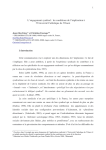
1
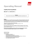
GENERATION OF PULSE WIDTH MODULATION (PWM) SIGNALS FOR THREE-PHASE 1 Jurnal Teknologi, 34(D) Jun 2001: 1–12 © Universiti Teknologi Malaysia GENERATION OF PULSE WIDTH MODULATION (PWM) SIGNALS FOR THREE- PHASE INVERTER USING A SINGLECHIP MICROCONTROLLER ZAINAL SALAM1 & KHOSRU MOHAMMAD SALIM2 Abstract. This paper describes the use of a general purpose microcontroller to generate the pulse width modulation (PWM) pulses for a three-phase inverter. The main feature of the work is the simplicity of the hardware – only a fixed point microcontroller with its associated internal peripheral is required. This result in an extremely simple, low-cost and reliable system. A laboratory inverter prototype using a Siemens 80C167 microcontroller is developed and typical results are presented. Key word: ergy. Microcontroller; inverter; pulse width modulation; power electronics, renewable en- Abstrak. Artikel ini menerangkan penggunaan pengawal mikro serbaguna untuk menjana denyut-denyut modulasi lebar jalur untuk penyongsang tiga fasa. Kelebihan utama teknik ini adalah keringkasan perkakasan – hanya sebuah pengawal mikro dengan peralatan dalaman sahaja diperlukan. Hasilnya adalah sebuah sistem yang ringkas, murah dan dapat dipercayai. Setelah prototaip penyongsang menggunakan pengawal mikro Siemens 80C167 telah dibangunkan dan beberapa hasil ujian diberikan. Kata kunci: 1.0 Pengawal mikro, penyongsong, denyut modulasi lebar jalur, elektronik kuasa. INTRODUCTION Recent developments in very large scale integration (VLSI) programmable devices have influenced the design of power electronics systems in ways which are inconceivable before. Proliferation of power electronics systems based on microprocessor (µP), microcontroller (µC), digital signal processor (DSP) and field programmable gate array (FPGA) signalled the numbered days of analogue systems. It is well accepted that the use of these advanced integrated circuits has significantly improve system performance. The scenario is expected to be irreversible as more powerful and faster chi ps enter the market. The main advantage of programmable devices is that it offers a considerable degree of flexibility in the overall system design. For example, in an embedded microcontroller system, complex functions can be implemented using software (and 1&2 Untitled-20 Power Electronics Research Group, Faculty of Electrical Engineering, Universiti Teknologi Malaysia, 81310 Skudai, Johor Darul Takzim, Malaysia. Email: [email protected] 1 02/16/2007, 17:11 2 ZAINAL SALAM & KHOSRU MOHAMMAD SALIM hardware) with execution speed comparable to analogue circuits. The flexibility of software allows functions to be altered as many times as required with minimal changes in hardware. Furthermore, suitable hardware parts can be replaced by software, which may results in reduced cost and increased reliability. For microcontrollers, the current trend is to pack sophisticated functions onto a single chip. It is common for microcontrollers to be equi pped with a wide range of on-chip peripherals such as analogue to digital converter, timers, interrupt controllers, networking facilities etc. In power electronics applications, these peripherals are very useful in real-time systems such as control and waveforms generation. This is the concept will that will be highlighted in this paper; the authors will demonstrate the use a l6-bit general purpose microcontroller in generating a three-phase PWM pulses for a DC to AC inverter. It will be shown that using this approach, power electronics systems can be designed with minimum external circuitry. Besides the above-mentioned task, the same microcontroller is also used for inverter control purpose, as described elsewhere by the authors [1]. 2.0 SIEMENS 80C167 MICROCONTROLLER This work demonstrates the use of the Seimen’s SAB 80CI67CR microcontroller to generate PWM pulses for a three-phase inverter system for fuel cell application. Internal SAB 80C167CR Internal Watchog XTAL PEC Osc. Interupt Controller Ext. Bus Con A D P1 P5 A S C A S C P0 Figure 1 Untitled-20 2 P3 G P T P W C A P C O M P2 Block diagram of Cl67 Microcontroller 02/16/2007, 17:11 GENERATION OF PULSE WIDTH MODULATION (PWM) SIGNALS FOR THREE-PHASE 3 Figure 1 shows the block diagram of the core CPU with its associated internal peripherals. Details on the IC can be found in [2]. The main peripherals that will be utilised in the waveform generations are briefly described below. For convenience the SAB 80C167 is abbreviated as C167. 2.1 PWM Module The C167 allows the generation of four independent PWM signals. Each signal is designated to a particular programmable output channel. The frequency range at 20 MHz CPU clock is from 4.8 Hz to 10 MHz for edge aligned and 2.4 Hz to 5 MHz for centre-aligned PWM, respectively. Figure 2 illustrates the output of a centre aligned PWM. The width of the pulse is determined by the content of the pulse width register (PWx), where x denotes a particular PWM channel. In a centre-aligned PWM the value in the pulse width register effects both edges of the output signal symmetrically, whereas in the edge-aligned, one of the edges is fixed. The minimum pulse width depend on the resolution of the PWM timer, PTx. For 20 MHz CPU clock, the resolution is 50 ns. The period of the pulse can be adjusted by changing the content the pulse period register, PPx. In the example shown below, the period is set to 7*2*50 ns, which turns out to be 700 ns. PPx Period=1 PTx count value PWx=1 PWx=2 PWx=3 PWx=4 PWx=5 PWx=6 PWx=7 LSR Change count direction LSR Figure 2 Centre-aligned PWM operation Untitled-20 3 02/16/2007, 17:11 4 2.2 ZAINAL SALAM & KHOSRU MOHAMMAD SALIM The Capture and Compare (CAPCOM) Unit In PWM, the pulse width (i.e. the numerical value of pulse width register) need to be changed dynamically with respect to the variation in the modulation index or ratio. The capture/compare (CAPCOM) unit can be effectively used to update the values in pulse width registers. The C167 provides two almost identical CAPCOM units. It can be programmed to capture the content of a timer on a specific internal or external event. Alternatively, it can be used to compare a specific timer content with a value in the CAPCOM register (known as the compare register) and modify the output signal when a match is met. Once met, an interrupt request is generated and it can be used to toggle an output port or jump elsewhere in the program to execute a specific task. Using the compare mode, the CAPCOM unit can be configured to generate pulse timing sequences with minimum software intervention. 2.3 Peri pheral Event Controller (PEC) For high frequency PWM operation, very fast data transfer from the CPU to a pulse width register is required. This can be achieved using the Peri pheral Event Controller (PEC). When an interrupt request from a CAPCOM unit occurs, the PEC responses to the request by moving a byte or word to the destination, i.e. to the pulse width register within a single CPU cycle. The result is that the pulse width register is updated almost immediately. The CI67 PEC provides 8 channels, which moves a single byte or word between two locations in memory. This is the fastest possible interrupt response available for data transfer. In most cases it is sufficient to service any peripheral request. 3.0 PWM GENERATION SCHEME EXAMPLE Using facilities provided by the above-mentioned peripherals, two PWM types for a three-phase inverter, namely regular sampling PWM and third harmonics injection PWM are implemented. Both schemes are well established and are widely reported in literature, for example [3–4]. The basic approach of signal generation is using the look-up table method. If the switching frequency is selected to be 10 KHz, the modulation ratio, i.e. the frequency ratio between the carrier wave and the modulating wave is 200. However, it should be noted that the number of PWM pulses in a full modulating period should be divisible by three. This is to avoid asynchronous PWM in a three-phase system to occur. The nearest number to 200 which is divisible by three is 198. Hence, for a complete modulating cycle, 198 data are required for the look-up table. Each data contains a numerical value which corresponds to the amplitude of the sinewave at a particular angle. The numerical peak value of the sinewave is set to Untitled-20 4 02/16/2007, 17:11 GENERATION OF PULSE WIDTH MODULATION (PWM) SIGNALS FOR THREE-PHASE 5 500. To avoid over-modulation (i.e. both positive and negative peak of sinewave should be within the magnitude of the triangular wave) the maximum amplitude (numerical value) of the modulating wave would be slightly less than the peak. For convenience, the maximum value of the modulating sinewaves is chosen to be 490. Thus, the value of the sinewave at each sampling point can be written as: 360° ( 2 * i + 1) (1) y = 490 * sin 2 * 198 Where i = 0, 1, 2, … up to 197. The exact number that need to be loaded into the pulse width register must therefore equal to Equation (1) multiplied by the modulation index. The latter varies form 0 to 1. Figure 3 shows the graphical presentation of the data in the look-up table for several angles of the sinewave. Sampling angle 0.90° 2.72° 1.81° 0° Modulating sinewave 4.55° 3.64° Figure 3 6.36° 5.45° 8.18° 7.27° 9.09° Position of sampling angle For harmonic injection sinusoidal PWM, the modulating wave equation is: 360D (2 * i + 1) 3 * 360D (2 * i + 1) y2 = 490 * 1.15 sin + 0.27 sin 2 *198 2 *198 9 * 360D ( 2 * i + 1) − 0.27 sin 2 *198 (2) Where i = 0, 1, 2, …up to 197. Formulation of regular sampling and harmonic injection PWM look-up tables are shown in Figures 4 and 5, respectively. Figure 6 shows the details for the pulse generation using an internal timer, CAMCOM and PWM module and PEC. The PWM frequency is set to 10 KHz. A specific time of the C167, i.e. TIMER 0 is used as to generate this frequency using its overflow interrupt. To obtain the correct timing, the upper and lower limits of TIMER 0 is set to 0FFF and 0FF05, respectively. The CAPCOM unit is configured to generate a single interrupt signal when a match is found. The compare values in the CAPCOM compare registers, i.e. CC0, CC1 and CC2 are chosen between 0FF05 to Untitled-20 5 02/16/2007, 17:11 6 ZAINAL SALAM & KHOSRU MOHAMMAD SALIM PEC source pointer phase-1 PEC source pointer: phase-1 Pulse Pulse PEC source pointer phase-2 PEC source pointer: phase-2 PEC source pointer phase-3 PEC source pointer: phase-3 Figure 4 Regular sampling look-up Figure 5 Harmonic injection sine look-up 0xFFFF.When TIMER 0 starts to count, three CAPCOM interrupts occur (due to the matches) within one PWM period. However, the occurrence of the interrupts are at different instants, specified by the values of CAPCOM registers. These interrupts are set to trigger the PEC channels. When CAPCOM interrupts occur, data from the PEC source pointers are transferred to the destination pointers through the PEC channels. In one PWM period, three new data are transferred from the look-up table to three different PWM registers. After each transfer, the source pointer is incremented by one and shifts to the next data location while the destination pointer remains fixed to the PWM registers. In a full length of 360° of the look-up table, all the source pointers are separated by 120° from each other to ensure the three-phase PWM are correctly generated. Untitled-20 6 02/16/2007, 17:11 GENERATION OF PULSE WIDTH MODULATION (PWM) SIGNALS FOR THREE-PHASE FFFFH CAPCOM Timer T0 C10 C11C12 T01C10 C11 C12 Interrupt Requests T01 C10 C11 C12 7 CC0 CC1 CC2 Reload T01 C10 C11 C12 T01 PWM module 1 for phase-1 PWM pulses of phase-1 PWM module-2 for phase-2 PWM pulses of phase-2 PWM module-3 for phase-3 P-132 P-133 P-134 P-135 PWM pulses of phase-3 Figure 6 Generation of three-phase PWM signals LEGEND (for Figure 6) CCx, (x =1,2,3): Content of Compare Register x. Clx: Interrupt Request for Compare Register x match's value of T0. T0: Interrupt Request for Timer0 (when overflows). Timer overflows means cycle is ended. TOREL Content of Reload Register of Timer0. This value is adjusted in such way that the time cycle of Timer0 is equal to PWM time set in the PWM module. P-1, P-2, P-3, …: are the pulse width values stored in the look up table starting at 00 of the modulating sinewave those generate the phase-l of the 3-phase sinusoidal PWM signals. P-66, P-67, P-68, …: are the pulse width values stored in the look up table starting at 120° of the modulating sinewave those generate the phase-2 of the 3-phase sinusoidal PWM signals. P-132, P-133, P-134, …: are the pulse width values stored in the look up table stating at 240° of the modulating sinewave those generate the phase-3 of the 3.phase sinusoidal PWM signals. Untitled-20 7 02/16/2007, 17:11 8 ZAINAL SALAM & KHOSRU MOHAMMAD SALIM 4.0 IMPLEMENTATION 4.1 Software The flowchart of the PWM generation program is shown in Figure 7. First, initialisation of all variables and peripheral ports take place. These include the setting of the switching frequency, configuring the CAPCOM compare values, initialising the PEC channels and setting all the interrupt priority levels. Next, the look-up table is prepared. Once the main program is executed, the system goes into an infinite interrupt driven loop. In this loop, the pulse width registers are updated. This is achieved by multiplying the basic data in the sinewave table with the current modulation index. The loop can be terminated by resetting the reset switch of the hardware boar. START Initialise variables Initialise ports, CAPCOM, PWM module, PEC and set all interrupts Initialise sine look-up table New Modulation Index Modify data in the look-up table No Reset? Yes END Figure 7 4.2 Flowchart for generation program Hardware The MCB-167-microcontroller evaluation board is used to develop, debug and execute C167 application programs. The board, manufactured by Kiel electronics, is Untitled-20 8 02/16/2007, 17:11 GENERATION OF PULSE WIDTH MODULATION (PWM) SIGNALS FOR THREE-PHASE 9 based on the C167 CPU with two memory devices, each of 512 kilobytes in size [5]. A wire wrap field is available for additional application hardware construction onboard. For communication with other computer systems, an RS232 serial link is provided. For 166/167 microcontroller applications, the Kiel CI66 Cross Compiler [6] offers a way to program in C, which truly matches assembly programming in terms of code efficiency and speed. The Kiel CI66 is a dedicated 166/167 C compiler that generates extremely fast and compact code. The Kiel CI66 Compiler implements the ANSI standard for the C language. 5.0 RESULTS Oscillograms of PWM waveforms (regular sampling and third harmonic injection PWM) using techniques described in the previous sections are presented. The results can be validated by established works such as [3–4]. Figure 8 Three-phase PWM gate signals at 10 KHz. Vertical scale: 2.0 V/div. Figures 8 shows the gate signals of the three phases for the regular sampling PWM. Figure 9 shows the same signal but at different time-scale, shown for clarity. It can be seen that the PWM gate signals are successfully generated using the proposed method. Figure 10 shows the line-to-line voltage waveform of regular sampling sinusoidal PWM signals at unity modulation index and supply voltage of 240 V. Figure 11 shows the line-to-line voltage waveform of harmonic injection sinusoidal PWM under the same condition. The Fast Fourier Transform of both sinusoidal and harmonic injection PWM waveforms at unity modulation index are shown in Figure 12 and l3 respectively. It is clear from the results that the fundamental com- Untitled-20 9 02/16/2007, 17:11 10 ZAINAL SALAM & KHOSRU MOHAMMAD SALIM Figure 9 Three-phase PWM signals at different time-scale Figure 10 Line to line voltage of sinusoidal PWM waveform. Vertical scale 240 V/div Figure 11 Untitled-20 Line to line voltage of harmonic injection sinusoidal PWM. Vertical scale: 240 V/div 10 02/16/2007, 17:11 GENERATION OF PULSE WIDTH MODULATION (PWM) SIGNALS FOR THREE-PHASE Figure 12 11 Line to line voltage and FFT of regular sampling PWM at unity modulation index Figure 13 Line to line voltage and FFT of harmonic injection PWM at unity modulation index ponent of the harmonic injection PWM is bigger than that of the sinusoidal PWM. This is consistent with results presented in [3–4]. Untitled-20 11 02/16/2007, 17:11 12 6.0 ZAINAL SALAM & KHOSRU MOHAMMAD SALIM CONCLUSION In this paper, the use of a low-cost microcontroller, i.e. SAB80C167, to generate the PWM pulses for a three-phase inverter is described. The main feature of the system is its simplicity; this is primarily due to the minimum hardware required. The peripherals of 80C167 such as PWM module, CAMCOM, and PEC are described and their functions in generating PWM signals are explained. Using the look-up table approach, two PWM generation schemes, namely regular sampling and harmonic injection method are implemented,. Several typical results are presented and they are found to agree well with other established works. REFERENCES [1] [2] [3] [4] [5] [6] Untitled-20 Zainal Salam, Khosru Mohammad Salim and Faridah Taha. 2000. Design and Development of a ThreePhase, 5kW Power Conditioning Unit for Fuel-cell Application. Journal – Institution of Engineers, Malaysia. 61(2): 71 -- 77. “SAB 80C166/83C167 16-bit CMOS Single-chip microcontro11ers for embedded control applications, User's Manual, Siemens AG. 1996. Bowes, S. R. 1975. New sinusoidal pulse width-modulated inverter. Proc. IEE. 122(11): 1279 -- 1285. Bowes, S. R. and Mount, M. J. 1981. Microprocessor control of PWM inverters. IEE proc., Pt. B. 128(6): 293 -- 305. Siemens, GmBH. 1995. MCB-167 prototype board with Siemens C167 CPU, User’s Guide 5.95, Kiel Electronics. Kiel, GmBH. 1992. C166 Professional Developers Kit, Kiel Software, GmbH. 12 02/16/2007, 17:11