1
PSZ 19:16 (Pind. 1/07)
UNIVERSITI TEKNOLOGI MALAYSIA
DECLARATION OF THESIS / UNDERGRADUATE PROJECT REPORT AND COPYRIGHT
Author’s full name : NURLIA SYAKILA BINTI CHE HUSIN
Date of Birth
: 29th JULY 1990
Title
: DIGITAL CHESS CLOCK USING PIC 16F877A MICROCONTROLLER
Academic Session : 2012/2013
I declare that this thesis is classified as:
CONFIDENTIAL
(Contains confidential information under the Official Secret Act
1972)*
RESTRICTED
(Contains restricted information as
organization where research was done)*
OPEN ACCESS
I agree that my thesis to be published as online open access
(full text)
specified
by
the
I acknowledged that Universiti Teknologi Malaysia reserves the right as follows:
1. The thesis is the property of Universiti Teknologi Malaysia
2. The Library of Universiti Teknologi Malaysia has the right to make copies for the
purpose of research only.
3. The Library has the right to make copies of the thesis for academic exchange.
Certified by:
NOTES:
SIGNATURE
SIGNATURE OF SUPERVISOR
900729-03-6168
(NEW IC NO/PASSPORT)
DR NASRUL HUMAIMI BIN MAHMOOD
NAME OF SUPERVISOR
Date: 24th JUNE 2013
Date: 24th JUNE 2013
*
If the thesis is CONFIDENTAL or RESTRICTED, please attach with the letter from
the organization with period and reasons for confidentiality or restriction.
“I hereby declare that I have read this thesis and in my
opinion this thesis is sufficient in terms of scope and quality for the
award of the degree of Bachelor of Engineering (Electrical- Electronics)”
Signature
: ………………………….........
Name of Supervisor
: Dr. Nasrul Humaimi bin Mahmood
Date
: 24th June 2013
DIGITAL CHESS CLOCK USING PIC 16F877A MICROCONTROLLER
NURLIA SYAKILA BINTI CHE HUSIN
A thesis submitted in fulfilment of the
requirements for the award of the degree of
Bachelor of Engineering (Electrical-Electronics)
Faculty of Electrical Engineering
Universiti Teknologi Malaysia
JUNE 2013
I declare that this thesis entitle “Digital Chess Clock using PIC 16F877A
Microcontroller” is the result of my own research except as cited in the references. The
thesis has not been accepted for any degree and is not concurrently submitted in
candidature of any other degree.
Signature: ……………………………………………
Name of: NURLIA SYAKILA BINTI CHE HUSIN
Date: 24th JUNE 2013
Dedicated, in thankful appreciation
for support, encouragement and understanding
to my beloved family members and friends.
ACKNOWLEDGEMENT
Alhamdulillah, thanks to Allah S.W.T. for His blessing and mercy, for giving me
strength to complete the final year project. Without His guidance surely this project
cannot be finish. In this given opportunity to express my deepest appreciation, I would
like to give my deepest grateful for those who help without wish for the return except
the knowledge will be continuous forever. First of all, I would like to extend my utmost
gratitude to my one and only supervisor, Dr. Nasrul Humaimi bin Mahmood for his
continuous guidance, support and invaluable advices to ensure that I will be able to
finish this project. The supervision and support he gave me has truly helped me in
progression and smoothness of this project and his cooperation is much appreciated.
Not to forgotten that I would like to give my appreciation to all my family members for
their support in my finance and understanding throughout the accomplishment of my
final year project. Special thanks also for all my beloved friends who help me direct or
indirectly in my project. Your help is much appreciated. Lastly, I would like to give my
special gratitude to University of Technology Malaysia (UTM) and all the staff for
providing the equipment and guidance throughout the completion process.
ABSTRACT
The purpose of this study is to design the alternative way of displaying digital
chess clock by using PIC 16F877A microcontroller. Two methods involve in design the
digital chess clock which is hardware design and software design. The PIC 16F877A
microcontroller along with PIC start-up kit SK40C has been proposed in this study to
design the digital chess clock using the microcontroller. The result of the simulation has
been shown using LCD display and an additional buzzer has been used as an alarm
system in the digital chess clock. The MPLAB IDE and PICkit2 software has been used
in this project to write the source code and to generate the hex file into microcontroller.
The IUC00B PIC programmer has been used in this project as an intermediate element
to connect the hardware design and software design. The result has shown the time limit
for the player to finish the game and the winner of the game if the other player cannot
complete the move in the time given.
ABSTRAK
Projek ini dilakukan bertujuan untuk mereka bentuk jalan lain untuk
memaparkan jam catur digital menggunakan mikropengawal PIC 16F877A. Dua kaedah
terlibat dalam mereka bentuk jam catur digital ini iaitu menggunakan mereka bentuk
perkakasan elektronik dan mereka bentuk perisian.
Mikropengawal PIC16F877A
bersama dengan kit permulaan mikropengawal SK40C telah digunakan dalam projek ini
untuk mencipta jam catur digital ini. Keputusan projek ini di tunjukkan melalui paparan
LCD dan alatan tambahan dalam projek ini iaitu „buzzer‟ telah digunakan sebagai sistem
penggera untuk jam catur digital. Untuk mereka bentuk perisian bagi projek ini, perisian
MPLAB IDE dan PICkit 2 telah digunakan untuk menulis kod dan menjana fail hex ke
dalam mikropengawal.
„Programmer PIC‟ telah digunakan sebagai komponen
perantaraan untuk menghubungkan perkakasan elektronik dan reka bentuk perisian.
Keputusan projek ini untuk melihat had masa untuk kedua-dua pemain dan pemenang
untuk permainan ini jika salah seorang pemain tidak dapat menyelesaikan gerakan catur
dalam masa yang ditetapkan.
TABLE OF CONTENTS
CHAPTER
1
TITLE
PAGE
DECLARATION
ii
DEDICATION
iii
ACKNOWLEDGEMENT
iv
ABSTRACT
v
ABSTRAK
vi
TABLE OF CONTENTS
vii
LIST OF TABLES
x
LIST OF FIGURE
xi
LIST OF ABBREVIATIONS
xiii
INTRODUCTION
1
1.1
Background
1
1.2
Problem statements
2
1.3
Objectives
2
1.4
Scope
2
1.5
Thesis Outline
3
2
LITERATURE REVIEW
5
2.1
Related Research
5
2.2
Background of Chess Clock
6
2.2.1
Analog Clock
6
2.2.2
Digital Clock
7
2.2.3
History of Chess Clock
7
2.2.3.1 Sandglass Clock
8
2.2.3.2 Mechanical Timing Device
9
2.3
3
Peripheral Interface Controller (PIC)
10
2.3.1
PIC 16F877A Microcontroller
10
2.3.2
SK40C PIC Startup Kit
13
2.3.3
IUC00B PIC Programmer
14
2.4
LCD Display
15
2.5
Software Implementation
16
2.5.1
MPLAB IDE Software
16
2.5.2
PICkit 2 Software
17
METHODOLOGY
19
3.1
Hardware Implementation
19
3.1.1
21
PIC 16F877A Connected to
SK40C Startup Kit and LCD Display
3.1.2
3.2
Buzzer Connection with Microcontroller
23
Software Design
24
3.2.1
24
Algorithm and Programming in
MPLAB IDE Software
3.2.1.1 Initialization of configuration for
27
PIC 16F877A Microcontroller
3.2.1.2 Initialization of Ports
27
3.2.1.3 Initialization of LCD
27
3.2.1.4 Initialization of Buzzer
28
3.2.2
3.2.1.5 Push Switch Button
28
3.2.1.6 Interrupt Explanation
28
MPLAB IDE and PICkit 2
29
Software Setup
4
5
3.2.2.1 MPLAB IDE Software Setup
29
3.2.2.2 PICkit 2 Software Setup
32
RESULT AND DISCUSSION
34
4.1
34
Result and Discussion
CONCLUSION
41
5.1
Conclusion
41
5.2
Problem
42
5.3
Recommendation
43
REFERENCES
44
APPENDICES
46
LIST OF TABLES
TABLE NO.
TITLE
PAGE
2.1
First Two Player Who Used Time Limit
9
3.1
Pin Connection of PIC 16F877A with SK40C
22
Startup Kit and LCD Display
LIST OF FIGURES
FIGURE NO.
TITLE
PAGE
2.1
Chess Clock with Pendulum
10
2.2
40 Pins of PIC 16F877A Microcontroller
11
2.3
Block Diagram of PIC16F877A Microcontroller
12
2.4
SK40C Startup Kit
13
2.5
IUC00B PIC Programmer
14
2.6
LCD Display Embedded to SK40C Startup Kit
15
2.7
MPLAB IDE Window for Source Code
17
2.8
Connected PICkit 2 Software with PIC Programmer
18
3.1
Block Diagram of Digital Chess clock using
20
PIC 16F877A Microcontroller
3.2
Circuit Diagram of Digital Chess Clock
21
3.3
Buzzer Connection of Digital Chess clock
23
3.4
Flow Chart of PIC 16F877A Main Program
25
3.5
Flow Chart of Interrupt Function
26
3.6
MPLAB IDE Programming Setup
29
3.7
Source Code of the Project
30
3.8
Successfully Build Program at MPLAB IDE
31
3.9
Successfully Connection of IUC00B PIC Programmer
32
3.10
Successfully Generate Hex File into PIC Microcontroller
33
4.1
Two Player Start the Chess Game
35
4.2
Time Taken for Player1 Move the Chess
36
4.3
Time Taken for Player2 Move the Chess
37
4.4
LCD Display for which Player Win and Lose
38
4.5
Game Over for Both Player
39
LIST OF ABBREVIATIONS
DGT
Digital Game Technology
FPGA
Field Programmable Gate Array
LCD
Liquid Crystal Display
LED
Light Emitting Diode
MPLAB IDE
MPLAB Integrated Development Environment
PIC
Peripheral Interface Controller
VHDL
VHSIC Hardware Description Language
CHAPTER 1
INTRODUCTION
1.1
Background
Chess is a game where two players play the game at the same. There was no
time limit to play the game in earlier days. Since there is no time limit, the game can
last for many hours.
To make the game more interesting and suitable for the
tournament, the chess clock was being design. The first clock is name as pendulum
clock and finally analogue chess clock was being design. To make the life easier, the
digital chess clock was being implemented. By designing this digital chess clock using
PIC microcontroller, the problem can be solved since this project is using programmable
microcontroller. To play the game, each player is given a finite time in completing the
game. The rules of the game is simple which is if one of the player run out of time first,
he will lose the game. The term for the time in chess game is chess clock. Nowadays,
there was no longer need of analogue clock because of not accurate time during play the
game.
2
1.2
Problem Statement
The existing digital clock is using the seven segment display that displays the
time limit for the game. This project will focus on displaying the time limit by using the
LCD display which is the other alternative than using seven segments. Other than that,
the other digital chess clock has only one function which is to show the time limit of the
game. This project will propose the other function of digital chess clock such as LED
light indicator and buzzer.
1.3
Objectives
The objectives of this project are:
1. To design the digital chess clock using PIC 16F877A and implement onto
board SK40C PIC start-up kit.
2. To interface LCD display to microcontroller.
1.4
Scope
In order to achieve the objectives of the project, there is several scopes need to
be highlighted. The scopes of the project include the hardware and software parts. For
the hardware part, chess clock circuit has been designed in order to display the time of
3
the game. The circuit consists of PIC 16F877A microcontroller, LCD display, buzzer
and LED light. The time will be displayed in LCD display. Since the LCD display was
much cheaper than to use 12 seven segment to display hour, minutes and seconds for
both player.
By using LCD display, we can display the time for both player
simultaneously. Apart of using LCD display to show the time limit, buzzer will be used
as an alarm to show that the player runs out of time and LED light will be used to show
which player move at that time.
For the software part, MPLAB IDE was used to do the programming and to
compile all source code used in the project. The software MPLAB IDE will then be
connected to PICkit 2 to program the source code into the microcontroller.
1.5
Thesis Outline
This thesis contains five chapter altogether. Chapter one describes the objective and
scope of this project as well as the problem statement of the project.
Chapter two will discuss more about the literature review and related researches
regarding designation of digital chess clock using PIC 16F877A. It well discuss about
the theory behind the electronics components used in the project.
In chapter three, the discussion will be on the methodology of the project and all the
steps involved for the hardware and software design.
4
Chapter four will discuss about the result and discussion of the project. All
photos about the project will be displayed in here. All result consists of hardware part
and software part. Both parts will be shown here. The discussion about the result of the
project will be discussed in detail here.
The last chapter of the thesis which is chapter five will conclude the project and
some recommendations for further works will be discuss here as well as the problem
involved during carrying out the project. All the problems will be list out here.
CHAPTER 2
LIRERATURE REVIEW
2.1
Related Research
Rosmira Roslan (2008) developed digital chess clock using the FPGA board.
The research is using the ISE software and FPGA Xilinx board. The designation of the
digital chess clock is using VHDL code. Chess clock are really two connected clocks.
While the player 1 is thinking, his clock is running and the player 2 clock stop running.
There is only one clock running at a time and each player has their own separate amount
of time. In blitz chess, each player has a finite amount of time for the entire game which
is only five minutes. If the time is up, the person who runs out of time will lose. This
type of game will make chess more interesting and fun to play.
M. Zhafri (2010) developed a speed chess clock for his research.
The
improvement of the speed chess clock is from analog clock to digital clock and
expensive chess clock to lower price of chess clock. His research investigates the used
of programmable microcontroller and the implementation of the PIC microcontroller.
6
The Speed Chess Clock (SCC) is a programmable clock that indicates player‟s turn by
LED. The buzzer is to indicate the time out is approaching and the double „beep‟ for the
time out.
His research introduces the LCD display to display the time and other
components as the output of the clock. The programmable microcontroller used in his
research was PIC 16F877A.
2.2
Background of Chess Clock
2.2.1
Analog Clock
In 1870 there was game played for the first time with the use of timer. There
was such a success that in 1883, it was recorded that the first tournament was played by
using a real chess clock with a pendulum. A time limit of 15 moves was regulated by
the connected stop clocks. When one clock was stopped, the other will start running and
vice versa. It was designed by Thomas Bright Wilson (1843-1915) of Manchester with
an advice from Blackburne. The first patent for a clock was issued in 1884 to Amandus
Schiewater of Liverpool. The clock was used by Steinitz-Lasker match for the world
championship in New York, 1894.
After five years in 1889, the flag was invented by Meijer, the secretary of the
Dutch Chess Federation. It was easier to see when the times run out because the flag fell
with time run out. In the early days of clocks, surpassing the time limit was not
considered losing a game. In the seventies, electric clocks were invented but it was
initially unsuccessful until Dutchmann Albert Vasse invented the DGT (digital game
technology) digital clock which is commonly used.
7
2.2.2
Digital Clock
After the implementing of the chess clocks, the Jaques “chess timing clock” was
introduced in the 1890s and sold for 21 shillings. In 1990, the analogue push-button was
then perfected by Veenhoff of Groningen. The first electronic chess clock was the
created by Bruce Cheney, a Cornell University Electrical Engineering student in 1973.
The first patent was granted to Joe Meshi on a fully operational microprocessor based
digital chess clock. Almost all chess tournaments today use digital clocks due to the
different time controls with delay or time increments added to a clock. The analogue
clock was not in use anymore because of inaccurate accuracy and many other problems.
2.2.3
History of Chess Clock
In the very early days, there were no time limit of how long will the chess game
will be played. In 1834, several famous matches between Louis La Bourdonnais and
Alexander McDonnell were recorded and at that time, time was not an issue. According
to George Walker, three quarter of one entire game “was spent in dwelling and
pondering and strategizing”. Many of the games lasted long bur the exact duration of
each move was not recorded.
Walker who there when the game between La
Bourdonnais and McDonnell once recorded the time for one move which is 55 minutes
for one move and then said that “ McDonnell was incomparably the slower player”. On
the other time in 1843, several impartial onlookers described that a match between
Howard Staunton and Pierre St.Amant as a test of a physical endurance rather than chess
match. It is reported that their 21st match game took 66 moves and 14 and half hour.
These caused the prolongations and attempts to fatigue and to wear out the opponent and
this showed that an average game lasted for nine hours.
8
Previously, chess was governed by an unwritten amateur privilege that allows
players play chess match with an unlimited time for each move. It was being recorded
that the Staunton-St.Amant average match game of 1843 games was nine hours and that
as much as two hours and 20 minutes was spent by one player for one single move in
London tournament. Because of the competitive chess game between the Bourdonnais
and McDonnell, there were some questions of fairness whether a game should be played
with an enormous amount of time. The rise of questions about the fairness of the game
slowly turns to inventing of the game with a time limit.
2.2.3.1 Sandglass Clock
Firstly suggested a maximum time limit of the match was famed French player
Alexandre deschapellas shortly after the Staunton matches. At the first-ever World
Tournament held in London in 1851, there was a contributor named A. Cantab to write
“Let each player have a three hour sandglass at his elbow and a friend on either side to
turn it. While the player is thinking, the sand must be allowed to run. While his
opponent is thinking, the sand must be laid horizontally on the table and the running
suspended”. This very first timing proposal was considered evaluating the entire cycle
of moves and not just one move.
After that, German chess master Baron von der Lasa proposed that each game
will be using two watches and the time was noted by each opponent. This proposal was
much better than using sandglass because of the accuracy using sandglass. It was
proven that problem such as temperature and humidity both affect the accuracy of the
sandglass. This method was quietly popular in Europe since the sandglass method was
proven to be problematic. In 1861, the game between Anderssen and von Kolisch was
9
the first match played with time limit by using sandglass. In London 1862, time controls
were novelties for a big tournament which is 24 moves had to be played in two hours
and time measured by sandglass.
Table 2.1 First Two Player Who Used Time Limit
No
FLAGS
NAME
01 02 03 04 05 06 07 08 09 TOTAL
01
Karl Ernst Adolf Anderssen
1 0 0 1 0 ½ 1 ½ 1 5.0/9
02
Baron Ignaz von Kolisch
0 1 1 0 1 ½ 0 ½ 0 4.0/9
2.2.3.2 Mechanical Timing Device
The first invented mechanical timing device was in 1883 to the delight of the
entire chess community. This chess clock made its debut in London in 1883 as the
invention of Thomas Bright Wilson of Manchester. It is similar to the states where two
identical pendulum clocks set on opposite ends of a balance beam. When one player
finished his move, he moved his clock into a position that stopped its pendulum and
started the opponent‟s timer. The „tumbling‟ clock was then manufactured by Fattorini
& Sons of Bradford in England.
The first tournament by using mechanical device timing and the time usage
during the games measured was when the tournament of London in 1851. The players
used more than two hours for a move and a several solution was came up such that a
time limit of five minutes for a move and fines for exceeding the time limit.
10
Figure 2.1 Chess Clock with Pendulum
2.3
Peripheral Interface Controller (PIC)
2.3.1
PIC 16F877A Microcontroller
PIC 16F877A microcontroller is a programmable microcontroller used to
generate many function of the device. Since this is a programmable microcontroller and
can generate many function, LED light indicator and buzzer is being defined [11].
Buzzer will be used as an alarm system and LED light as an indicator.
The
configuration of the microcontroller is easy compared to other microcontroller. So the
microcontroller can help the setting of the digital chess clock easier since the
microcontroller has many functions.
11
Figure 2.2 40 Pins of PIC 16F877A Microcontroller
Figure 2.2 show the 40 pins of PIC 16F877A microcontroller.
This
microcontroller has Port A to Port D and other pins. These 40 pins microcontroller has
programmed flash 8K words, data memory 368 bytes and data EEPROM 256 bytes [12].
Each pin has the own function [12] to be used. Port B is used as output port and other
port can be used as input or output port. The full block diagram of the PIC 16F877A
will be shown on figure 2.3.
12
Figure 2.3 PIC 16F877A Block Diagram
13
2.3.2
SK40C PIC Startup Kit
SK40C PICkit is a 40 pins PIC microcontroller start - up kit. This start-up kit
comes with additional features such as [11]:
2 x programmable switch
2 x LED indicator
Turn pin for crystal
USB on board
PICkit port
Figure 2.4 SK40C Start-up Kit
The advantage of using this start- up kit is that the LED and switch is already
connected. With the existence of this PICkit, the life becomes easier. SK40C come
with UIC00A/B ICSP USB programmer connector to import the hex file into the
microcontroller.
14
2.3.3
IUC00B PIC Programmer
Figure 2.5 shows the IUC00B PIC programmer connected to SK40C PICkit and
USB connected to computer [11]. This programmer function as the intermediate device
to import the hex file generated in MPLAB IDE software into the microcontroller.
IUC00B PIC
Programmer
Figure 2.5 IUC00B PIC Programmer
15
2.4
LCD Display
The 2 x 16 character LCD display offer character display for an embedded
system. This LCD display can be used to display numerical information, text and
special symbol [11]. For this project, the LCD display is used to show the time limit of
chess clock and the text of who win and lose the game. This concept of using the time
limit in playing chess game was almost the same with Blitz chess [6]. Figure 2.4 shows
the LCD display embedded to the SK40C start-up kit.
LCD
Display
Figure 2.6 LCD Display Embedded to SK40C Start-up Kit
16
2.5
Software Implementation
2.5.1
MPLAB IDE Software
MPLAB IDE software is a Windows based Integrated Development
Environment for the Microchip Technology Incorporated PIC microcontroller (MCU)
and dsPIC digital signal controller (DSC) families [13]. In the MPLAB IDE, we can:
i.
Create source code using the built in editor.
ii.
Assemble, compile and link source code using various language tools.
assembler, linker and librarian come with MPLAB IDE.
An
C compilers are
available from Microchip and other third party vendors.
iii.
Debug the executable logic by watching program flow in real time emulator such
as MPLAB IDE.
iv.
Make timing measurements
v.
View variables in watch windows.
17
Figure 2.7 MPLAB IDE Window for Source Code
2.5.2
PICkit 2 Software
PICkit 2 software is used to generate hex file into the microcontroller. The hex file
is gotten from the successfully build program with MPLAB IDE software.
The
connected UIC00B PIC programmer and SK40C start-up kit will then generate the hex
file into microcontroller.
The connected programmer will find the type of
microcontroller used. Ensure the type of microcontroller find in the PICkit 2 software is
same as the selected microcontroller in the MPLAB IDE software. This software used
to import the hex file generated in the MPLAB IDE to the microcontroller. The correct
hex file will then generate the output for the hardware design. The entire step to setup
the PICkit 2 software will be discussed in detail in methodology part. Figure 2.8 shows
18
the connected PICkit 2 software with IUC00B PIC programmer. The 3FFF stated in the
window shows the ready state of software to import the hex file and write into the
microcontroller.
Figure 2.8 Connected PICkit 2 Software with PIC Programmer
CHAPTER 3
METHODOLOGY
3.1
Hardware Implementation
The hardware implementation of the project consists of PIC 16F877A
microcontroller and LCD display connected to SK40C start-up kit. All components
were being connected using bread board. Block diagram of the project is shown in
figure 3.1.
20
PIC 16F877A
Microcontroller
LCD Display
SK40C Start-up Kit
Buzzer
Figure 3.1 Block Diagram of Digital Chess Clock using PIC 16F877A
Figure 3.1 shows the block diagram of implementation of hardware design of
digital chess clock. The PIC 16F877A microcontroller was connected to SK40C start-up
kit and connected to buzzer through bread board. The SK40C PICkit is already have
LED light embedded inside. The connected PIC 16F877A and SK40C start-up kit will
then connect with LCD display. The LCD display used to display the time limit of the
chess game and show the winner and loser of the game.
After that, connect the
hardware implementation to PIC programmer UIC00B to program the source code to
PIC microcontroller. The PIC microcontroller will save the source code inside until new
source is being replaced.
Figure 3.2 shows the circuit diagram of the hardware
implementation of the project.
21
Figure 3.2 Circuit Diagram of the Hardware Implementation
3.1.1
PIC 16F877A Connected to SK40C Startup Kit and LCD Display
The connection of the LCD display to the SK40C startup kit is to display the
time limit of the chess game. Table 3.1 shows the pins connection of PIC 16F877A to
the LCD display. Pins that are not stated in the table are not used and left hanging. The
microcontroller that connected with power supply will then receive the desired output
22
and display it at the LCD. The programmed microcontroller will operate until reset
button is push.
Table 3.1 Pin Connection of PIC 16F877A with SK40 Startup Kit and LCD Display
Pin
Name
Pin Function
Connection
1
GND
Ground
GDN
2
VDD
Positive Supply for LCD
5V
3
CON
Brightness Adjust
Connected to Preset to
Adjust Brightness
4
RB4
Select Register, Select
Pin RS of LCD
Instruction or Data Register
5
GND
Ground
GND
6
RB5
Start Data Read or Write
Pin E of LCD
7
RD0
LCD Data Bus Pin
Pin D0 of LCD
8
RD1
LCD Data Bus Pin
Pin D1 of LCD
9
RD2
LCD Data Bus Pin
Pin D2 of LCD
10
RD3
LCD Data Bus Pin
Pin D3 of LCD
11
RD4
LCD Data Bus Pin
Pin D4 of LCD
12
RD5
LCD Data Bus Pin
Pin D5 of LCD
13
RD6
LCD Data Bus Pin
Pin D6 of LCD
14
RD7
LCD Data Bus Pin
Pin D7 of LCD
15
VDD
Backlight Positive Input
VDD
16
B/L
Backlight Negative Input
Connected to JP8
RA6
OSC2
Crystal
Turn Pin (JP7)
RA7
OSC1
Crystal
Turn Pin (JP7)
RB0
SW1
Digital Input
“SW1” Switch
RB1
SW2
Digital Imput
“SW2” Switch
RB2
Buzzer
Alarm Output
Pin 35 PIC 16F877A
23
3.1.2
Buzzer Connection with Microcontroller
Buzzer that acts as an alarm system in this digital chess clock will be connected
at pin 35 on PIC 16F877A microcontroller and ground. This alarm system will sound as
the time limit for the game runs out. The connection of the buzzer is given in figure 3.3.
Figure 3.3 Buzzer Connection of Digital Chess Clock
24
3.2
Software Design
3.2.1
Algorithm and Programming in MPLAB IDE Software
An algorithm has been developed to make the microcontroller read the input and
display the output accordingly.
The algorithm has been established and been
represented by a flowchart in figure 3.4 and figure 3.5. The flowchart is then translated
into C language and compiled using MPLAB IDE, the PIC 16F877A microcontroller
software development tool.
appendix.
The source code for the program can be referred in
25
Start
Initialization
Initialize configuration
Initialize PORT
Initialize LCD
Initialize Buzzer
SW2 == 0
No
Yes
SW1 = =0
LED1 = 1
LED2 = 1
Delay
Figure 3.4 Flow Chart of PIC16F877A Main Program
26
Call Delay 1ms
No
TMROIF = 1
Yes
Counter = Counter + 1
Buzzer = 1
Return
Figure 3.5 Flow Chart of Interrupt Function
There are three main parts of main program in microcontroller. The initialization
of configuration, ports, LCD and buzzer, push switch button, LED light indicator. There
also three parts in the interrupt process which are Timer0, counter and buzzer.
27
3.2.1.1 Initialization of configuration for PIC16F877A
Before starting to write the program, the PIC16F877A need to configure first.
The configuration of the PIC 16F877A is given in source code of the program in
appendix.
3.2.1.2 Initialization of Ports
In this project, we used Port B, RB0, RB1 and RB2 as an input ports and Port D,
RD0 until RD7 as an output. When the input Port B high (=1), it will send an output to
Port D to display the output.
3.2.1.3 Initialization of LCD
All pins of LCD need to be connected to the SK40C startup kit and the
initialization of the ports given in the appendix. The initialization of ports for LCD is set
as Port D as an output.
28
3.2.1.4 Initialization of Buzzer
Buzzer that act as an alarm system need to be initialize so that the program work
accordingly. The initialization of the buzzer is the RB2 will be defining as buzzer and
the connection is at table 3.1.
3.2.1.5 Push Switch Button
According to the flow chart at figure 3.4, if the SW2=0, LED1 will light up and
vice versa. The process will continue until one of the player run out of time.
3.2.1.6 Interrupt Explanation
Firstly, the Timer0 needs to enable first so that the counter will increment. The
counter will increment until the time limit for the player finish. Buzzer will sound as the
time finish.
29
3.2.2
MPLAB IDE and PICkit 2 Software Setup
3.2.2.1 MPLAB IDE Software Setup
When install MPLAB Integrated Development Environment (IDE), we need to
ensure that HI-TECH PICC-Lite also install. This HI-TECH PICC-Lite is the third
compiler for PIC16 families. Open the MPLAB IDE to start a new project start to write
the coding. After that, build the source code to check the error. If there are no error, a
message will „Build successful‟ will appear in output window. After compile the source
code, the software will automatically generate the hex file that will be used by PICkit 2
software. The setup of the software will be shown below.
Figure 3.6 MPLAB IDE Programming Setup
30
Figure 3.7 Source Code of the Project
31
Successfully build
program
Figure 3.8 Successful Build Program at MPLAB IDE
32
3.2.2.2 PICkit 2 Software Setup
This software is use only to import the hex file onto the PIC microcontroller.
Connect the UIC00B PIC programmer to computer and check the connection of the PIC
programmer by clicking tool menu.
Figure 3.9 Successful Connection of IUCOOB PIC Programmer
33
Hex file successfully
generated
Figure 3.10 Successfully Generate Hex File into PIC 16F877A
CHAPTER 4
RESULT AND DISCUSSION
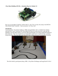
4.1
Result and Discussion
The result will show the time digital of chess clock. For the demonstration of the
project, the time limit for each player is only for 10 seconds. Each player both will have
10 seconds to move the chess and the player who do not move in the time limit will be
consider lose in the game.
35
P1 stand for
P2 stand for
Player1
Player2
Figure 4.1 Two Player Start the Chess Game
Figure 4.1 shows the two players who will start the game. Both players are set to
have hour, minutes and seconds in their time. At the LCD display above, P1 stand for
player 1 and P2 stand for player 2.
36
LED1 for
player1
Figure 4.2 Time Taken for Player1 to Move the Chess
Figure 4.2 above shows that the time taken for the player 1 to make one move for
the game. Red LED1 will light up to show that it is the player 1 turn to move. After
player 1 is done with move, player 2 has to start move because the time already set to
counter. Before this, the digital chess clock uses only show the time but in this digital
chess clock, there will be two LED light for two players and a buzzer to alarm the
player. This LED will be used as an indicator to show which player move at a time and
the people around them will know which player‟s turn without asking anywhere. This
LED light is also important in the tournament since this game will need high
concentration and the viewer can look at the game and know the player‟s turn without
asking. In case of the player do not move the chess in the time limit, the buzzer will
sound and the game is over. Figure 4.3 will show the time taken for the player 2 to
move and the yellow LED2 will light up.
37
LED2 for
player 2
Figure 4.3 Time Taken for Player2 to Move the Chess
Figure 4.3 show that the time taken for the player to move a chess. As we can
see from the figure 4.3, the time taken for the player 2 to complete the move is 2
seconds. Since he can complete the move before time limit, he is saves in this round and
player 1 will continue with his move. As the player 2 move the chess clock, LED2 will
light up to show that it is player 2 turn.
38
Figure 4.4 LCD Display for Which Player Win and Lose
The figure 4.4 above shows that the player 2 that lose in the game. The reason
for the player 2 to lose is because the time taken for the player 2 is already 10 seconds.
Since this demonstration only take 10 seconds for each player, the player who do not
move in the time limit will lose in the game. Along with the LCD display to show
which player who lose in the game, the buzzer will sound so that the player will know
that he lost in the game.
39
Figure 4.5 Game Over for Both Player
Figure 4.5 shows the game over for both of the players if there were no move in
the 30 seconds time. This digital chess clock already being set if there were no move in
30 seconds time, both players will lose the game. This time limit of the 30 seconds is to
ensure that the game will follow the standard time so that no lagging time in the game. It
also to ensure both players will start play as soon as possible because the time already
starts after the ON button was pressed.
This digital chess clock is set to have 10 seconds for each player but the time
limit for both players can be change higher in the source code. This time limit is only
for the demonstration only. Since the button SW1 and SW2 for both players is not like
the other switch, so if the player 1 wishes to start the game, he must press the button
SW1 along with move the chess game because the time will stop if he stops to press.
40
The switch will detect the time only if the switch was being pressed. This type of switch
need to be replace so that the players will not have to press the switch all the time.
The buzzer that used in this digital chess clock was only used for the alarm for
the player. Since the sound may or may not distract other players in the tournament, the
buzzer can be change to other type or the time for the buzzer to sound will be limit so
that the sound does not distract other players. The control of the switch, LED, LCD
display and buzzer are all in the source code. So, to change the setting of the program,
we just have to modify a little bit of the program.
CHAPTER 5
CONCLUSION
5.1
Conclusion
The digital chess clock is an important and easier clock to be used in the chess
tournament.
This digital chess clock will give finite time for the players in the
tournament. Since this digital chess clock using additional functionality such as LED
light and buzzer, the digital chess clock will be much effective other than existing digital
chess clock.
As a conclusion, this digital chess clock using PIC 16F877A was unsuccessfully.
The first objective was successfully because the designation and implementation of the
chess clock onto the board SK40C start-up kit was successful. The interfacings of LCD
display to microcontroller and applying the PIC microcontroller and implement it onto
hardware installation also successful but the total design of the digital chess clock is not
successful since the time limit is not accurate. To show the successful hardware design,
42
the time is being shown at LCD display. The digital chess clock that has other function
except for time is successfully developed.
This digital chess clock has other function such as LED light as an indicator and
buzzer that acts an alarm system. This buzzer will sound if the player runs out of time.
Apart from that, the digital chess clock was being designed as a low cost hardware.
Since the price of the other existing digital chess clock with microcontroller is expensive
and most tournament still used old clock, so the implementation of the digital chess
clock meet the criteria of affordable device.
5.2
Problem
The problem arise in the project are the connection of the project is not accurate.
This can cause the reading of the time in LCD display is not accurate. Since the design
of the digital chess clock is incomplete, the time limit of the chess clock is not accurate.
The timing of the digital chess clock is not multitasking since it can only read until 10
seconds only.
43
5.3
Recommendation
In order to commercialize the device to the pubic used, some improvements needs to
be done. So, for the future work, some other function of the digital chess clock needs to
be added so the clock becomes much more interesting.
Other than that, the switch button needs to be replaced so that the player does not
have to press the switch all the time. The alarm system also needs to change because the
sound is too loud. For the LED light, the LED light will make it blink so that the device
becomes more interesting.
44
REFERENCES
1. Tony Foley. Chess Magic. Irish Chess Journal. August 2011. Pg. 03.
2. Nasrul Humaimi. And Che Ku Mohd Solahuddin. Smart Electronic Chess Board
Using Reed Switch. Jurnal Teknologi. Vol. 55. 2011. Pg. 41-52
1.
3. M. Zhafri M. Yaacob. Speed Chess Clock. Universiti Teknikal Malaysia Melaka.
April 2010
4. Albert A. Monichino. Chess Clock Hearing Procedure. Asian Dispute Review. Hong
Kong International Arbitration Centre. July 2009.
5. Rosmira Roslan. Digital Chess Clock. Universiti Malaysia Pahang. 2008
6. Mark E. Appel. Management Technique for Complex Cases.. Dispute Resolution
Journal. May 2006. pg. 83-86
7. Elo, A. The ratings of chess players, past and present. New York: Arco. 1978.
8. De Groot, A. Thought and choice in chess. The Hague Mouton. 1965
9. Wissen 1st Matt. Chess Base 12. 2012
45
10. Marie Brannon. History of Timers and Clocks in Chess Matches. 2009.
11. Cytron Tech. SK40C User Manual. March 2011.
12. Microchip. PIC 16F877A Microcontroller Data Sheet. 2003
13. MPLAB IDE. Simulator. Editor‟s User Guide.
46
APPENDIX
Program in PIC16F877A for Digital Chess Clock
//=============================================================
//Author
: NURLIA SYAKILA BINTI CHE HUSIN
//Project
: DIGITAL CHESS CLOCK USING PIC 16F877A
MICROCONTROLLER
//=============================================================
//
include
//=============================================================
#include <htc.h>
#include "lcd.h"
#include "system.h"
__CONFIG(0x3F32);
#define buzzer
RB2
//Function prototype
void interrupt ISR(void);
void delay1(unsigned long i);
void ADC_read(void);
47
unsigned short read_temp(void);
void clock(void);
int j;
int k;
unsigned short counter=0;
//Main Function
unsigned short result;
unsigned short temp;
void main(void)
{
ADRESH=0;
ADRESL=0;
ADCON1=0b11000010;
TRISA=0b00000010;
// set AN1 as input port
TRISB=0b00001011;
// set PORTB RB0-RB2 as input
TRISD=0b00000000;
// set PORTD as OUTPUT
GIE = 1;
//Enable Global Interrupt
INTE = 0;
//Enable RB0/INT external Interrupt
PEIE = 0;
//Disable all unmasked peripheral interrupt
TMR0IE=1;
T0CS=0;
T0SE=0;
PSA=0;
PS2=1;
PS1=1;
PS0=1;
//set prescale 1:4
48
PORTA = 0;
// clear PORT
PORTB = 0;
PORTD = 0;
lcd_initialize();
lcd_clear();
lcd_goto(0x00);
lcd_putstr("P1-H:M:S");
lcd_goto(0x08);
lcd_putstr("P2-H:M:S");
while(1)
{
if(SW2==0) //player1
{
LED1=1;
LED2=0;
j=j++;
lcd_goto(0x47);
lcd_bcd(1,j);
delay1(135135);
if(j==9)
{
lcd_goto(0x40);
lcd_putstr("Lose");
lcd_goto(0x48);
lcd_putstr("Win");
j=j;
}
49
}
else if(SW1==0) //player2
{
LED2=1;
LED1=0;
k=k++;
lcd_goto(0x4F);
lcd_bcd(1,k);
delay1(135135);
if(k==9)
{
lcd_goto(0x40);
lcd_putstr("Win");
lcd_goto(0x48);
lcd_putstr("Lose");
k=k;
}
}
}
delay(10000);
}
//subroutine DELAY
void delay1(unsigned long i)
{
for(;i>0;i--);
}
50
//subroutine INTERRUPT TIMER0
void interrupt ISR(void)
{
TMR0IF=1;
counter++;
if(counter==4578)
{
buzzer=1;
lcd_goto(0x40);
lcd_putstr("GAME OVER");
}
TMR0IF=0;
}
// clear the interrupt flag