1
QUANTAR®/QUANTRO®
RADIO SERVICE SOFTWARE INSTRUCTION
MANUAL
© 2006 MOTOROLA, INC.
ALL RIGHTS RESERVED
PRINTED IN U.S.A.
6881085E35-AG
12/30/2006
Computer Software Copyrights
The Motorola products described in this document include a copyrighted Motorola computer program. Laws in the United States and other
countries, as well as International Treaties, preserve for Motorola the exclusive rights for Motorola’s copyrighted computer programs, including
the exclusive right to copy, reproduce, distribute, or otherwise transfer said computer program(s). Accordingly, the copyrighted Motorola
computer programs contained in this document may not be copied, decompiled, reverse engineered, or reproduced in any manner and on or
within any media without the express written permission of Motorola. Furthermore, the purchase of Motorola products shall not be deemed to
grant either directly or by implication, estoppel, or otherwise, any license under the copyrights, patents, or patent applications of Motorola,
except for the normal non-exclusive, royalty-free license to use that arises by operation of law in the sale of a product.
Document Copyrights
© Motorola, Inc. All rights reserved.
No duplication or distribution of this document or any portion thereof shall take place without the express written permission of Motorola. No part
of this document may be reproduced, distributed, or transmitted in any form or by any means, electronic or mechanical, for any purpose without
the express written permission of Motorola.
To order additional copies of this document contact your Motorola sales representative.
Disclaimer
The information in this document is carefully examined, and is believed to be entirely reliable. However, no responsibility is assumed for
inaccuracies. Furthermore, Motorola reserves the right to make changes to any products herein to improve readability, function, or design.
Motorola does not assume any liability arising out of the applications or use of any product or circuit described herein; neither does it cover any
license under its patent rights nor the rights of others.
Trademark Information
The following are registered trademarks of Motorola, Inc.: Motorola, the Motorola logo, ASTRO, ASTRO-TAC, EMBASSY, FullVision,
INTELLIREPEATER, QUANTAR, QUANTRO, and SMARTZONE.
The following are Motorola trademarks: CENTRACOM Elite, CENTRACOM Series, CENTRACOM Gold Series, MOSCAD, SECURENET, and
Wireless Network Gateway.
HP, HP-UX, OpenView, Vectra, and Hewlett Packard are registered trademarks of Hewlett-Packard Corporation.
UNIX is a registered trademark of The Open Group in the United States and other countries.
Any other brand or product names are trademarks or registered trademarks of their respective holders.
WARRANTY
Limited Software Warranty
For the first ninety (90) days following its initial shipment, Motorola warrants that when properly used, its software will be free from reproducible
defects that cause a material variance from its published specification. However, Motorola does not warrant that program operation will be
uninterrupted or error- free, that each defect will be corrected, or that any program will meet Licensee’s particular requirements.
This warranty does not cover an item of Software (i) used in other than its normal and customary manner; (ii) subjected to misuse; or (iii)
subjected to modifications by Licensee or by any party other than Motorola without the prior written consent of Motorola.
Limited Media Warranty
For the first ninety (90) days following its initial shipment, Motorola warrants that the media carrying the software will be free from defects that
damage the performance of the software. Motorola will replace any damaged media free of charge during the warranty period. Warranted media
is limited to that which is used to transport the software (such as floppy disks and authorization key). PROMs that may store the software in
equipment are not covered under this warranty.
Limitation of Liability
Motorola’s total liability and Licensee’s sole remedy for any warranted software shall be limited to, at Motorola’s option, software replacement or
the payment of Licensee’s actual damages, not to exceed the total licensed charge paid by Licensee to Motorola for the item of software that
caused the damage.
The warranties set forth above extend only to the first licensee. Subsequent transferees accept these programs “as is” and without warranties of
any kind. This warranty is given in lieu of all other warranties, express or implied, including, without limitation, the warranties of
merchantability and fitness for a particular purpose.
In no event shall Motorola be liable for special, incidental, or consequential damages (including, without limitation, loss of use, time or data,
inconvenience, commercial loss, and lost profits or savings) to the full extent that such may be disclaimed by law even if Motorola has been
advised of the possibility of such damage against licensee by any other party.
Repair of Defects
The classification of defects in Motorola-supplied software shall be the responsibility of Motorola. Remedy of defects is at the sole discretion of
Motorola. If Motorola agrees to remedy a software defect, the new software will be warranted until the end of the original limited warranty period.
Replacement of any software defect shall constitute Motorola supplying the Licensee with the appropriate software media and authorization
key. Field installation and configuration are not included. Field software updates/upgrades and new enhancement option software will be
warranted for ninety (90) days from the date of initial shipment.
All warranty service will be performed at service locations designated by Motorola. Travel and associated expenses of the Licensee or such
expenses incurred by Motorola for visits to Licensee’s location by Motorola personnel are not covered by this warranty.
TABLE
OF
CONTENTS
Table of Contents
...................................
....
Chapter 1: Introduction
Intended User Profile . . . . . . . . . . . . . . . . . . . . . . . . . . . . . . . . . . . . . . . . . . . . . . . . . . . . . . . . . . . . . . . . 1-1
Organization of this Guide . . . . . . . . . . . . . . . . . . . . . . . . . . . . . . . . . . . . . . . . . . . . . . . . . . . . . . . . . . . . 1-2
Related Manuals. . . . . . . . . . . . . . . . . . . . . . . . . . . . . . . . . . . . . . . . . . . . . . . . . . . . . . . . . . . . . . . . . . . . 1-3
Chapter 2: RSS Overview
Summary of Features . . . . . . . . . . . . . . . . . . . . . . . . . . . . . . . . . . . . . . . . . . . . . . . . . . . . . . . . . . . . . . . . 2-1
User Interface Description . . . . . . . . . . . . . . . . . . . . . . . . . . . . . . . . . . . . . . . . . . . . . . . . . . . . . . . . . . . . 2-2
PC Requirements . . . . . . . . . . . . . . . . . . . . . . . . . . . . . . . . . . . . . . . . . . . . . . . . . . . . . . . . . . . . . . . . . . . 2-4
Installing the RSS Software . . . . . . . . . . . . . . . . . . . . . . . . . . . . . . . . . . . . . . . . . . . . . . . . . . . . . . . . . . . 2-4
Removing a Previous RSS Version . . . . . . . . . . . . . . . . . . . . . . . . . . . . . . . . . . . . . . . . . . . . . . . . . . . . 2-10
Repairing an Installation . . . . . . . . . . . . . . . . . . . . . . . . . . . . . . . . . . . . . . . . . . . . . . . . . . . . . . . . . . . . . 2-12
Connecting the PC to the Device RSS Port . . . . . . . . . . . . . . . . . . . . . . . . . . . . . . . . . . . . . . . . . . . . . . 2-12
Working with the RSS Program . . . . . . . . . . . . . . . . . . . . . . . . . . . . . . . . . . . . . . . . . . . . . . . . . . . . . . . 2-14
Launching the RSS Program . . . . . . . . . . . . . . . . . . . . . . . . . . . . . . . . . . . . . . . . . . . . . . . . . . . 2-14
Exiting the RSS Program. . . . . . . . . . . . . . . . . . . . . . . . . . . . . . . . . . . . . . . . . . . . . . . . . . . . . . 2-15
Reading the Device Codeplug . . . . . . . . . . . . . . . . . . . . . . . . . . . . . . . . . . . . . . . . . . . . . . . . . . . . . . . . 2-15
Navigating Through the RSS Screens. . . . . . . . . . . . . . . . . . . . . . . . . . . . . . . . . . . . . . . . . . . . 2-19
Writing Codeplug Data to the Device . . . . . . . . . . . . . . . . . . . . . . . . . . . . . . . . . . . . . . . . . . . . . . . . . . . 2-21
Obtaining Codeplug Size . . . . . . . . . . . . . . . . . . . . . . . . . . . . . . . . . . . . . . . . . . . . . . . . . . . . . . . . . . . . 2-22
File Maintenance . . . . . . . . . . . . . . . . . . . . . . . . . . . . . . . . . . . . . . . . . . . . . . . . . . . . . . . . . . . . . . . . . . 2-22
Saving Configuration Data to an Archive File . . . . . . . . . . . . . . . . . . . . . . . . . . . . . . . . . . . . . . 2-23
Opening an Archive Codeplug File . . . . . . . . . . . . . . . . . . . . . . . . . . . . . . . . . . . . . . . . . . . . . . 2-25
Chapter 3: Optimization
Required Test Equipment . . . . . . . . . . . . . . . . . . . . . . . . . . . . . . . . . . . . . . . . . . . . . . . . . . . . . . . . . . . . . 3-2
Verifying the Device’s Configuration Data . . . . . . . . . . . . . . . . . . . . . . . . . . . . . . . . . . . . . . . . . . . . . . . . 3-3
Device Type Programming Overview . . . . . . . . . . . . . . . . . . . . . . . . . . . . . . . . . . . . . . . . . . . . . . . . . . . . 3-4
Programming the IP Address . . . . . . . . . . . . . . . . . . . . . . . . . . . . . . . . . . . . . . . . . . . . . . . . . . . . . . . . . . 3-6
Programming the MAC Address . . . . . . . . . . . . . . . . . . . . . . . . . . . . . . . . . . . . . . . . . . . . . . . . . . . . . . . . 3-7
Setting the Device’s Date and Time . . . . . . . . . . . . . . . . . . . . . . . . . . . . . . . . . . . . . . . . . . . . . . . . . . . . . 3-8
Programming Wireline Configuration Data . . . . . . . . . . . . . . . . . . . . . . . . . . . . . . . . . . . . . . . . . . . . . . . . 3-8
Programming the Access Code Table Data For Conventional Systems . . . . . . . . . . . . . . . . . . . . . . . . 3-13
Programming the Access Code Table Data for 6809 Trunking Systems . . . . . . . . . . . . . . . . . . . . . . . . 3-15
68 8 10 85 E3 5 -A G
1 2 /3 0 /2 00 6
I
TABLE OF CONTENTS
Programming the Multi-Coded Squelch Table Screen . . . . . . . . . . . . . . . . . . . . . . . . . . . . . . . . . . . . . .3-16
Saving User Information . . . . . . . . . . . . . . . . . . . . . . . . . . . . . . . . . . . . . . . . . . . . . . . . . . . . . . .3-17
Adding New Users . . . . . . . . . . . . . . . . . . . . . . . . . . . . . . . . . . . . . . . . . . . . . . . . . . . . . . . . . . .3-17
Modifying an Existing User . . . . . . . . . . . . . . . . . . . . . . . . . . . . . . . . . . . . . . . . . . . . . . . . . . . . .3-18
Deleting an Existing User . . . . . . . . . . . . . . . . . . . . . . . . . . . . . . . . . . . . . . . . . . . . . . . . . . . . . .3-19
Programming the Channel Information Screen . . . . . . . . . . . . . . . . . . . . . . . . . . . . . . . . . . . . . . . . . . . .3-20
Programming the TRC Commands Data. . . . . . . . . . . . . . . . . . . . . . . . . . . . . . . . . . . . . . . . . . . . . . . . .3-25
Programming DC Remote Command Data . . . . . . . . . . . . . . . . . . . . . . . . . . . . . . . . . . . . . . . . . . . . . . .3-27
Programming the RF Configuration Data Screen . . . . . . . . . . . . . . . . . . . . . . . . . . . . . . . . . . . . . . . . . .3-29
Programming the 6809 Trunking Interface Data . . . . . . . . . . . . . . . . . . . . . . . . . . . . . . . . . . . . . . . . . . .3-31
Programming the Scan List Configuration Data . . . . . . . . . . . . . . . . . . . . . . . . . . . . . . . . . . . . . . . . . . .3-32
Programming the IntelliRepeater. . . . . . . . . . . . . . . . . . . . . . . . . . . . . . . . . . . . . . . . . . . . . . . . . . . . . . .3-35
Programming the Site Frequency Parameters . . . . . . . . . . . . . . . . . . . . . . . . . . . . . . . . . . . . . .3-36
Programming the Site General Parameters . . . . . . . . . . . . . . . . . . . . . . . . . . . . . . . . . . . . . . . .3-37
Programming the Site Timer Screen . . . . . . . . . . . . . . . . . . . . . . . . . . . . . . . . . . . . . . . . . . . . .3-39
Programming Radio Modulation Partition Screens. . . . . . . . . . . . . . . . . . . . . . . . . . . . . . . . . . .3-40
Programming Full/Sub Band Partition Screens . . . . . . . . . . . . . . . . . . . . . . . . . . . . . . . . . . . . .3-40
Programming Repeater Summary Screen . . . . . . . . . . . . . . . . . . . . . . . . . . . . . . . . . . . . . . . . .3-41
Programming the Repeater Information Screen . . . . . . . . . . . . . . . . . . . . . . . . . . . . . . . . . . . . .3-41
Programming RF Configuration . . . . . . . . . . . . . . . . . . . . . . . . . . . . . . . . . . . . . . . . . . . . . . . . .3-44
Programming the Codeplug Data into a Conventional or 6809 Station or ASTRO-TAC Comparator . . .3-46
Programming the Codeplug Data into an IntelliRepeater Station Installed in a SmartZone
2.0.3 or 2.7E System . . . . . . . . . . . . . . . . . . . . . . . . . . . . . . . . . . . . . . . . . . . . . . . . . . . . . . . . . . . . . . . .3-48
Programming the Codeplug Data into an IntelliRepeater Station Installed in a SmartZone
3.0, 3.5, or 4.1 System . . . . . . . . . . . . . . . . . . . . . . . . . . . . . . . . . . . . . . . . . . . . . . . . . . . . . . . . . . . . . .3-51
Performing Station Alignment . . . . . . . . . . . . . . . . . . . . . . . . . . . . . . . . . . . . . . . . . . . . . . . . . . . . . . . . .3-54
Required Test Equipment . . . . . . . . . . . . . . . . . . . . . . . . . . . . . . . . . . . . . . . . . . . . . . . . . . . . . .3-55
RX and TX Wireline Alignment . . . . . . . . . . . . . . . . . . . . . . . . . . . . . . . . . . . . . . . . . . . . . . . . . .3-55
Procedure A: Rx Wireline Alignment Procedure . . . . . . . . . . . . . . . . . . . . . . . . . . . . . .3-57
Procedure B: Rx Wireline Equalization Alignment Procedure . . . . . . . . . . . . . . . . . . . .3-59
Procedure C: Status Tone Level Alignment Procedure . . . . . . . . . . . . . . . . . . . . . . . . .3-63
Procedure D: Optional Hi Boost Fine Tuning Procedure . . . . . . . . . . . . . . . . . . . . . . . .3-64
Procedure E: Aligning TX Wireline Procedure. . . . . . . . . . . . . . . . . . . . . . . . . . . . . . . .3-66
Procedure F: Aligning ASTRO Link Management Tone Procedure . . . . . . . . . . . . . . .3-68
Aligning Radio Signal Strength Indicator (RSSI) . . . . . . . . . . . . . . . . . . . . . . . . . . . . . . . . . . . .3-68
Aligning Squelch Adjust Procedure . . . . . . . . . . . . . . . . . . . . . . . . . . . . . . . . . . . . . . . . . . . . . .3-71
Equalizing Batteries . . . . . . . . . . . . . . . . . . . . . . . . . . . . . . . . . . . . . . . . . . . . . . . . . . . . . . . . . .3-73
For QUANTAR Stations: . . . . . . . . . . . . . . . . . . . . . . . . . . . . . . . . . . . . . . . . . . . . . . . .3-73
For Quantro Stations: . . . . . . . . . . . . . . . . . . . . . . . . . . . . . . . . . . . . . . . . . . . . . . . . . .3-75
Calibrating Reference Oscillator Procedure . . . . . . . . . . . . . . . . . . . . . . . . . . . . . . . . . . . . . . . .3-75
Reference Oscillator Calibration: Internal Reference Oscillator - Manual Procedure . .3-75
Reference Oscillator Calibration: Internal Reference Oscillator - Auto-Net Procedure .3-77
Reference Oscillator Calibration: External Reference Oscillator . . . . . . . . . . . . . . . . . .3-78
II
6 88108 5E35 -A G
1 2/30 /200 6
RADIO SERVICE SOFTWARE INSTRUCTION MANUAL
TABLE OF CONTENTS
Reference Oscillator Calibration: Internal Ultra High Stability Oscillator (UHSO). . . . . 3-78
Setting ASTRO Tx Align and Test Procedure . . . . . . . . . . . . . . . . . . . . . . . . . . . . . . . . . . . . . . 3-82
Generating ASTRO Test Patterns . . . . . . . . . . . . . . . . . . . . . . . . . . . . . . . . . . . . . . . . . . . . . . . 3-85
TDATA Calibration (6809 Trunking Station Only) . . . . . . . . . . . . . . . . . . . . . . . . . . . . . . . . . . . 3-88
ASTRO Bit Error Rate Reports . . . . . . . . . . . . . . . . . . . . . . . . . . . . . . . . . . . . . . . . . . . . . . . . . 3-90
Post-Optimization Checkout . . . . . . . . . . . . . . . . . . . . . . . . . . . . . . . . . . . . . . . . . . . . . . . . . . . . . . . . . . 3-93
Chapter 4: Optimizing the ASTRO-TAC Comparator
Verifying the Comparator’s Configuration Data . . . . . . . . . . . . . . . . . . . . . . . . . . . . . . . . . . . . . . . . . . . . 4-2
Programming the Comparator . . . . . . . . . . . . . . . . . . . . . . . . . . . . . . . . . . . . . . . . . . . . . . . . . . . . . . . . . 4-3
Programming the Hardware Configuration Screen . . . . . . . . . . . . . . . . . . . . . . . . . . . . . . . . . . . 4-3
Programming the Conventional System Screen . . . . . . . . . . . . . . . . . . . . . . . . . . . . . . . . . . . . . 4-5
Programming the Smartzone System Screen . . . . . . . . . . . . . . . . . . . . . . . . . . . . . . . . . . . . . . . 4-6
Programming the Analog Voting Screen . . . . . . . . . . . . . . . . . . . . . . . . . . . . . . . . . . . . . . . . . . . 4-6
Programming the Port Control Screen. . . . . . . . . . . . . . . . . . . . . . . . . . . . . . . . . . . . . . . . . . . . . 4-7
Performing Comparator Alignment . . . . . . . . . . . . . . . . . . . . . . . . . . . . . . . . . . . . . . . . . . . . . . . . . . . . . . 4-9
Equalizing Batteries . . . . . . . . . . . . . . . . . . . . . . . . . . . . . . . . . . . . . . . . . . . . . . . . . . . . . . . . . . 4-10
Reference Oscillator Calibration Procedures. . . . . . . . . . . . . . . . . . . . . . . . . . . . . . . . . . . . . . . 4-10
Internal Reference Oscillator – Auto-Net Procedure . . . . . . . . . . . . . . . . . . . . . . . . . . 4-11
External Reference Oscillator Calibration. . . . . . . . . . . . . . . . . . . . . . . . . . . . . . . . . . . 4-11
Chapter 5: Diagnostics and Status
Station/Comparator Status Messages . . . . . . . . . . . . . . . . . . . . . . . . . . . . . . . . . . . . . . . . . . . . . . . . . . . 5-1
Station Metering Screens . . . . . . . . . . . . . . . . . . . . . . . . . . . . . . . . . . . . . . . . . . . . . . . . . . . . . . 5-2
Station/Comparator Status Report Screen . . . . . . . . . . . . . . . . . . . . . . . . . . . . . . . . . . . . . . . . . 5-3
Station/Comparator-Generated Status Messages . . . . . . . . . . . . . . . . . . . . . . . . . . . . . 5-5
Station Status Panel Screen . . . . . . . . . . . . . . . . . . . . . . . . . . . . . . . . . . . . . . . . . . . . . . . . . . . 5-26
Comparator Status Panel Screen . . . . . . . . . . . . . . . . . . . . . . . . . . . . . . . . . . . . . . . . . . . . . . . 5-28
Station/Comparator Software Version . . . . . . . . . . . . . . . . . . . . . . . . . . . . . . . . . . . . . . . . . . . . 5-30
Setting Date and Time . . . . . . . . . . . . . . . . . . . . . . . . . . . . . . . . . . . . . . . . . . . . . . . . . . . . . . . . . . . . . . 5-30
Codeplug Reports. . . . . . . . . . . . . . . . . . . . . . . . . . . . . . . . . . . . . . . . . . . . . . . . . . . . . . . . . . . . . . . . . . 5-31
Printing a Codeplug Report . . . . . . . . . . . . . . . . . . . . . . . . . . . . . . . . . . . . . . . . . . . . . . . . . . . . 5-31
Saving the Codeplug Report to a File . . . . . . . . . . . . . . . . . . . . . . . . . . . . . . . . . . . . . . . . . . . . 5-32
Remote Station Disabling/Enabling . . . . . . . . . . . . . . . . . . . . . . . . . . . . . . . . . . . . . . . . . . . . . . . . . . . . 5-33
ASTRO-TAC Diagnostics . . . . . . . . . . . . . . . . . . . . . . . . . . . . . . . . . . . . . . . . . . . . . . . . . . . . . . . . . . . . 5-34
Chapter 6: Performing Post Repair Alignment
Overview of Alignment Routines . . . . . . . . . . . . . . . . . . . . . . . . . . . . . . . . . . . . . . . . . . . . . . . . . . . . . . . 6-1
Test Equipment for Post-Repair Alignment Procedures . . . . . . . . . . . . . . . . . . . . . . . . . . . . . . . . . . . . . . 6-4
Aligning Power Output Procedure . . . . . . . . . . . . . . . . . . . . . . . . . . . . . . . . . . . . . . . . . . . . . . . . . . . . . . 6-4
Aligning Power Output Procedure for a Quantro 350 W VHF Station . . . . . . . . . . . . . . . . . . . . . . . . . . . 6-7
Aligning Tx Deviation Gain Adjust Procedure, 350 W VHF Stations . . . . . . . . . . . . . . . . . . . . . . . . . . . 6-11
Aligning Reference Modulation Compensation Procedure . . . . . . . . . . . . . . . . . . . . . . . . . . . . . . . . . . . 6-14
68 8 10 85 E3 5 -A G
1 2 /3 0 /2 00 6
III
TABLE OF CONTENTS
Chapter 7: Version Compatibility and Upgrades
Prior to Release R07.02.02 . . . . . . . . . . . . . . . . . . . . . . . . . . . . . . . . . . . . . . . . . . . . . . . . . . . . . . . . . . . .7-1
Beginning with Release R7.02.02 . . . . . . . . . . . . . . . . . . . . . . . . . . . . . . . . . . . . . . . . . . . . . . . . . . . . . . .7-2
RSS Program Version and Station Firmware Relationship . . . . . . . . . . . . . . . . . . . . . . . . . . . . . . . . . . . .7-2
RSS Program Versions Compatibility . . . . . . . . . . . . . . . . . . . . . . . . . . . . . . . . . . . . . . . . . . . . . . . . . . .7-16
Retrieving Station Software Versions . . . . . . . . . . . . . . . . . . . . . . . . . . . . . . . . . . . . . . . . . . . . . . . . . . .7-17
Retrieving Comparator Software Versions and Backplane ID. . . . . . . . . . . . . . . . . . . . . . . . . . . . . . . . .7-18
Performing Upgrades . . . . . . . . . . . . . . . . . . . . . . . . . . . . . . . . . . . . . . . . . . . . . . . . . . . . . . . . . . . . . . .7-19
Upgrading the Station’s Codeplug . . . . . . . . . . . . . . . . . . . . . . . . . . . . . . . . . . . . . . . . . . . . . . .7-19
Upgrading an Archived Codeplug File . . . . . . . . . . . . . . . . . . . . . . . . . . . . . . . . . . . . . . . . . . . .7-21
Features and System Capabilities. . . . . . . . . . . . . . . . . . . . . . . . . . . . . . . . . . . . . . . . . . . . . . . . . . . . . .7-22
Chapter 8: Password Protection
How Password Protection Works . . . . . . . . . . . . . . . . . . . . . . . . . . . . . . . . . . . . . . . . . . . . . . . . . . . . . . .8-1
Password Time-out. . . . . . . . . . . . . . . . . . . . . . . . . . . . . . . . . . . . . . . . . . . . . . . . . . . . . . . . . . . .8-1
Activating Password Protection . . . . . . . . . . . . . . . . . . . . . . . . . . . . . . . . . . . . . . . . . . . . . . . . . .8-1
Special Password Protection Features. . . . . . . . . . . . . . . . . . . . . . . . . . . . . . . . . . . . . . . . . . . . .8-2
Creating the Station’s Password . . . . . . . . . . . . . . . . . . . . . . . . . . . . . . . . . . . . . . . . . . . . . . . . . . . . . . . .8-2
Changing Station Password . . . . . . . . . . . . . . . . . . . . . . . . . . . . . . . . . . . . . . . . . . . . . . . . . . . . . . . . . . .8-3
Erasing Station Password (Local Access). . . . . . . . . . . . . . . . . . . . . . . . . . . . . . . . . . . . . . . . . . . . . . . . .8-4
Erasing Station Password (Remote Access). . . . . . . . . . . . . . . . . . . . . . . . . . . . . . . . . . . . . . . . . . . . . . .8-5
Bypassing the Station Password . . . . . . . . . . . . . . . . . . . . . . . . . . . . . . . . . . . . . . . . . . . . . . . . . . . . . . . .8-6
Chapter 9: Remote Dial-Up
Modem Requirements . . . . . . . . . . . . . . . . . . . . . . . . . . . . . . . . . . . . . . . . . . . . . . . . . . . . . . . . . . . . . . . .9-2
Station Modem Configuration . . . . . . . . . . . . . . . . . . . . . . . . . . . . . . . . . . . . . . . . . . . . . . . . . . . . . . . . . .9-2
PC Modem Configuration . . . . . . . . . . . . . . . . . . . . . . . . . . . . . . . . . . . . . . . . . . . . . . . . . . . . . . . . . . . . .9-3
Chapter 10: WildCard Operation
Station Auxiliary Inputs . . . . . . . . . . . . . . . . . . . . . . . . . . . . . . . . . . . . . . . . . . . . . . . . . . . . . . . . . . . . . .10-2
Programming the WildCard Input Screen . . . . . . . . . . . . . . . . . . . . . . . . . . . . . . . . . . . . . . . . . .10-2
Station Auxiliary Outputs . . . . . . . . . . . . . . . . . . . . . . . . . . . . . . . . . . . . . . . . . . . . . . . . . . . . . . . . . . . . .10-4
Programming the Wildcard Output Screen . . . . . . . . . . . . . . . . . . . . . . . . . . . . . . . . . . . . . . . . .10-5
State/Action Tables . . . . . . . . . . . . . . . . . . . . . . . . . . . . . . . . . . . . . . . . . . . . . . . . . . . . . . . . . . . . . . . . .10-6
How State/Action Tables Operate . . . . . . . . . . . . . . . . . . . . . . . . . . . . . . . . . . . . . . . . . . . . . . .10-7
Programming the Wildcard State Screen . . . . . . . . . . . . . . . . . . . . . . . . . . . . . . . . . . . . . . . . . .10-8
Chapter 11: Software Downloading
Prerequisites . . . . . . . . . . . . . . . . . . . . . . . . . . . . . . . . . . . . . . . . . . . . . . . . . . . . . . . . . . . . . . . . . . . . . .11-2
Preparing PC for Software Download Communications . . . . . . . . . . . . . . . . . . . . . . . . . . . . . . . . . . . . .11-3
Adding a Null Modem Device in Microsoft Windows 2000 Professional . . . . . . . . . . . . . . . . . .11-3
Adding a Null Modem in Windows 2000 Professional . . . . . . . . . . . . . . . . . . . . . . . . . .11-3
IV
6 88108 5E35 -A G
1 2/30 /200 6
RADIO SERVICE SOFTWARE INSTRUCTION MANUAL
TABLE OF CONTENTS
Adding a SLIP Connection in Windows 2000 Professional for a Null Modem
Connection . . . . . . . . . . . . . . . . . . . . . . . . . . . . . . . . . . . . . . . . . . . . . . . . . . . . . . . . . . 11-7
Adding a Dial-Up Modem Device in Microsoft Windows 2000 Professional . . . . . . . . . . . . . . 11-14
Adding a Dial-Up Modem in Windows 2000 Professional . . . . . . . . . . . . . . . . . . . . . 11-15
Adding a SLIP Connection in Windows 2000 Professional for a Dial-Up Modem
Connection . . . . . . . . . . . . . . . . . . . . . . . . . . . . . . . . . . . . . . . . . . . . . . . . . . . . . . . . . 11-17
Adding a Null Modem Device in Microsoft Windows XP Professional. . . . . . . . . . . . . . . . . . . 11-22
Adding a Null Modem in Windows XP Professional . . . . . . . . . . . . . . . . . . . . . . . . . . 11-22
Adding a SLIP Connection in Windows XP Professional for a Null Modem
Connection . . . . . . . . . . . . . . . . . . . . . . . . . . . . . . . . . . . . . . . . . . . . . . . . . . . . . . . . . 11-27
Adding a Dial-Up Modem Device in Microsoft Windows XP Professional . . . . . . . . . . . . . . . . 11-34
Adding a Dial-Up Modem in Windows XP Professional . . . . . . . . . . . . . . . . . . . . . . . 11-34
Adding a SLIP Connection in Windows XP Professional for a Dial-Up Modem
Connection . . . . . . . . . . . . . . . . . . . . . . . . . . . . . . . . . . . . . . . . . . . . . . . . . . . . . . . . . 11-36
RSS SLIP Connection Naming Convention . . . . . . . . . . . . . . . . . . . . . . . . . . . . . . . . . . . . . . . . . . . . . 11-45
Naming Convention for Null Modem install. . . . . . . . . . . . . . . . . . . . . . . . . . . . . . . . . 11-45
Naming Convention for Dial-Up Modem install. . . . . . . . . . . . . . . . . . . . . . . . . . . . . . 11-46
Connecting to the Device . . . . . . . . . . . . . . . . . . . . . . . . . . . . . . . . . . . . . . . . . . . . . . . . . . . . . . . . . . . 11-46
Serial (Direct) Connection . . . . . . . . . . . . . . . . . . . . . . . . . . . . . . . . . . . . . . . . . . . . . . . . . . . . 11-47
Ethernet Connections . . . . . . . . . . . . . . . . . . . . . . . . . . . . . . . . . . . . . . . . . . . . . . . . . . . . . . . 11-48
Remote Dial-Up Connections . . . . . . . . . . . . . . . . . . . . . . . . . . . . . . . . . . . . . . . . . . . . . . . . . 11-49
Zone Controller Link Connection . . . . . . . . . . . . . . . . . . . . . . . . . . . . . . . . . . . . . . . . . . . . . . . 11-49
Loading Station Software Files onto the PC. . . . . . . . . . . . . . . . . . . . . . . . . . . . . . . . . . . . . . . . . . . . . 11-52
Downloading Software to Station/Receiver Memory - Conventional and 6809 Controller
Systems or ASTRO-TAC Comparator Memory . . . . . . . . . . . . . . . . . . . . . . . . . . . . . . . . . . . . . . . . . . 11-52
Downloading Software to IntelliRepeater Memory . . . . . . . . . . . . . . . . . . . . . . . . . . . . . . . . . . . . . . . . 11-56
Appendix A: PL/DPL Codes
Appendix B: dBm to Microvolts Conversion
Appendix C: Glossary
Appendix D: Acronyms
68 8 10 85 E3 5 -A G
1 2 /3 0 /2 00 6
V
TABLE OF CONTENTS
THIS PAGE INTENTIONALLY LEFT BLANK.
VI
6 88108 5E35 -A G
1 2/30 /200 6
LIST
OF
FIGURES
List of Figures
...................................
....
Figure 2-1
Figure 2-2
Figure 2-3
Figure 2-4
Figure 2-5
Figure 2-6
Figure 2-7
Figure 2-8
Figure 3-1
Figure 3-2
Figure 3-3
Figure 3-4
Figure 3-5
Figure 3-6
Figure 3-7
Figure 3-8
Figure 3-9
Figure 3-10
Figure 3-11
Figure 3-12
Figure 3-13
Figure 3-14
Figure 3-15
Figure 3-16
Figure 3-17
Figure 3-18
Figure 3-19
Figure 3-20
Figure 3-21
Figure 3-22
Figure 3-23
Figure 3-24
Figure 3-25
Figure 3-26
Figure 3-27
Figure 3-28
68 8 10 85 E3 5 -A G
RSS Window Overview ..................................................................................... 2-2
RSS Toolbar Buttons ......................................................................................... 2-3
RSS Menus ....................................................................................................... 2-3
Null-Modem Cable Wiring Diagram................................................................. 2-13
RSS Cable Connections .................................................................................. 2-13
Connection Screen Window ............................................................................ 2-16
RSS Information and Function Screens .......................................................... 2-21
Codeplug Size Information Window ................................................................ 2-22
Accessing the IP Address Field......................................................................... 3-6
Accessing the MAC Address Field .................................................................... 3-7
Set Date and Time Screen ................................................................................ 3-8
Wireline Configuration Screen Examples – Analog Only Station Type ............. 3-9
Wireline Configuration Screen Tab Examples – ASTRO Capable or
ASTRO CAI Capable Station Type ................................................................. 3-10
Access Code Table Screens ........................................................................... 3-13
Access Code Table Screens ........................................................................... 3-15
Multi-Coded Squelch Table Screen................................................................. 3-16
Save Report Button to Save MCS Data .......................................................... 3-17
Channel Configuration Screen ........................................................................ 3-20
Advanced Channel Information Screen........................................................... 3-21
TRC Command Table Screen ......................................................................... 3-25
DC Command Table Screen ........................................................................... 3-28
RF Configuration Screens ............................................................................... 3-29
6809 Trunking Interface Screen ...................................................................... 3-31
Scan List Configuration Screen....................................................................... 3-33
IntelliRepeater Specific Configuration Screens ............................................... 3-35
Site Frequency Screen.................................................................................... 3-36
Site General Screen ........................................................................................ 3-37
Site Timer Screen............................................................................................ 3-39
Radio Modulation Partition Screen.................................................................. 3-40
Full/Sub Band Partition and Radio Modulation Partition Screen ..................... 3-41
Repeater Summary Screen............................................................................. 3-41
Repeater Information Screen - Basic Tab ....................................................... 3-42
Repeater Information Screen - Advanced Tab................................................ 3-42
RF Configuration Screen - Conventional Stations........................................... 3-45
RF Configuration Screen - IntelliRepeater and 6809 Trunking Stations ......... 3-45
TX Wireline Alignment Setup .......................................................................... 3-67
1 2 /3 0 /2 00 6
VII
LIST OF FIGURES
Figure 3-29
Figure 3-30
Figure 4-1
Figure 4-2
Figure 4-3
Figure 4-4
Figure 4-5
Figure 4-6
Figure 5-1
Figure 5-2
Figure 5-3
Figure 5-4
Figure 5-5
Figure 5-6
Figure 5-7
Figure 5-8
Figure 6-1
Figure 6-2
Figure 6-3
Figure 6-4
Figure 6-5
Figure 6-6
Figure 7-1
Figure 7-2
Figure 7-3
Figure 7-4
Figure 7-5
Figure 7-6
Figure 7-7
Figure 7-8
Figure 7-9
Figure 7-10
Figure 7-11
Figure 7-12
Figure 7-13
Figure 7-14
Figure 7-15
Figure 7-16
Figure 7-17
Figure 7-18
VIII
RSSI Alignment Test Setup ............................................................................ 3-69
Squelch Adjust Alignment Setup..................................................................... 3-71
Comparator Configuration Screen .................................................................... 4-3
Hardware Configuration Screen........................................................................ 4-4
Conventional System Screen............................................................................ 4-5
Smartzone System Screen ............................................................................... 4-6
Analog Voting Screen ....................................................................................... 4-7
Port Control Screen........................................................................................... 4-8
Station Metering Screen Example..................................................................... 5-3
Station Status Report Screen Example............................................................. 5-4
Comparator Status Report Screen Example..................................................... 5-5
Station Status Panel Screen Example ............................................................ 5-27
Status Panel Screen Example: Primary Comparator in an Expanded
Configuration................................................................................................... 5-28
Status Panel Screen Example: Standard Comparator.................................... 5-29
Station and Comparator Version Screens....................................................... 5-30
Example of a Saved Codeplug Report............................................................ 5-33
Reference Oscillator Alignment Screen ............................................................ 6-2
Power Output Alignment Setup ......................................................................... 6-5
Power Output Alignment Setup for Quantro 350W Stations ............................. 6-8
Tx Deviation Gain Adjust Alignment Setup ..................................................... 6-12
Reference Modulation Compensation Alignment Setup ................................. 6-14
Waveform Examples ....................................................................................... 6-16
Release R1.00 Features and System Capabilities – Conventional ................. 7-22
Release R2.00 Features and System Capabilities - Conventional ................. 7-23
Release R3.00 / R3.01 Features and System Capabilities - Conventional ..... 7-24
Release R4.00 Features and System Capabilities - Conventional ................. 7-25
Release R5.00 Features and System Capabilities - Conventional ................. 7-26
Release R6.00 Features and System Capabilities - Conventional ................. 7-27
Release R7.00 Features and System Capabilities - Conventional ................. 7-28
Release R07.02.02 Features and System Capabilities - Conventional .......... 7-29
Release R08.00.00-R08.03.00 Features and System
Capabilities - Conventional ............................................................................. 7-30
Release R09.00.00 Features and System Capabilities - Conventional .......... 7-31
Release R09.02.01 Features and System Capabilities - Conventional .......... 7-32
Release R09.03.00 Features and System Capabilities - Conventional .......... 7-33
Release R09.05.00/R09.06.00 Features and System Capabilities Conventional ................................................................................................... 7-34
Release R09.07.00/R10.00.00 through R10.08.00, R10.11.00, R10.12.00
Features and System Capabilities - Conventional .......................................... 7-35
Release R12.01.00 through R12.03.00 Features and System Capabilities Conventional ................................................................................................... 7-36
Release R13.00.00 through R13.02.00 Features and System Capabilities Conventional ................................................................................................... 7-37
Release R14.0.00 Features and System Capabilities - Conventional ............ 7-38
Release R2.00 Features and System Capabilities - 6809 Trunking ............... 7-39
6 88108 5E35 -A G
1 2/30 /200 6
RADIO SERVICE SOFTWARE INSTRUCTION MANUAL
Figure 7-19
Figure 7-20
Figure 7-21
Figure 7-22
Figure 7-23
Figure 7-24
Figure 7-25
Figure 7-26
Figure 7-27
Figure 7-28
Figure 7-29
Figure 7-30
Figure 7-31
Figure 7-32
Figure 7-33
Figure 7-34
Figure 7-35
Figure 7-36
Figure 7-37
Figure 7-38
Figure 7-39
Figure 9-1
Figure 10-1
Figure 10-2
Figure 10-3
Figure 11-1
Figure 11-2
Figure 11-3
Figure 11-4
Figure 11-5
Figure 11-6
68 8 10 85 E3 5 -A G
LIST OF FIGURES
Release R3.00 / R3.01 Features and System Capabilities: 6809 Trunking .... 7-40
Release R4.00 Features and System Capabilities - 6809 Trunking ................ 7-41
Release R5.00 Features and System Capabilities - 6809 Trunking ................ 7-42
Release R6.00 Features and System Capabilities - 6809 Trunking ................ 7-43
Release R7.00 Features and System Capabilities - 6809 Trunking ................ 7-44
Release R07.02.02 Features and System Capabilities - 6809 Trunking ......... 7-45
Release R09.00.00 Features and System Capabilities - 6809 Trunking ......... 7-46
Release R09.02.01 Features and System Capabilities - 6809 Trunking ......... 7-47
Release R09.03.00 Features and System Capabilities - 6809 Trunking......... 7-48
Release R09.05.00/R09.06.00/R09.07.00/R10.00.00 through R10.08.00,
R10.11.00, R10.12.00 Features and System
Capabilities - 6809 Trunking ............................................................................ 7-49
Release R12.01.00 through R12.03.00 Features and System Capabilities 6809 Trunking ................................................................................................. 7-50
Release R13.00.00 through R14.00.00 Features and System Capabilities 6809 Trunking ................................................................................................. 7-51
Release SZ2.0 Features and System Capabilities - IntelliRepeater
Trunking .......................................................................................................... 7-52
Release SZ2.3 Features and System Capabilities - IntelliRepeater
Trunking .......................................................................................................... 7-52
Release SZ2.7/2.7E Features and System Capabilities - IntelliRepeater
Trunking .......................................................................................................... 7-52
Release 12.00.00 through 12.02.00 Features and System Capabilities IntelliRepeater SZ2.0.3 Trunking..................................................................... 7-53
Release 12.00.00 through 12.02.00 Features and System Capabilities IntelliRepeater SmartZone 3.0/3.5/4.1 Trunking ............................................. 7-53
Release 13.00.00 through 13.02.00 Features and System Capabilities IntelliRepeater SmartZone 3.0/3.5/4.1 Trunking ............................................. 7-54
Release 14.00.00 Features and System Capabilities - IntelliRepeater
SmartZone 3.0/3.5/4.1Trunking ....................................................................... 7-54
Release 14.02.00 Features and System Capabilities - IntelliRepeater
SmartZone 3.0/3.5/4.1Trunking ....................................................................... 7-54
Release 14.00.00 Features and System Capabilities - IntelliRepeater
SmartZone 2.0.3 Trunking ............................................................................... 7-55
Remote Dial-Up Connection.............................................................................. 9-1
WildCard Input Screen - Enhanced Shown ..................................................... 10-3
WildCard Output Screen - Enhanced Shown .................................................. 10-5
WildCard State Screen.................................................................................... 10-8
Serial Connection for Software Download ..................................................... 11-47
Ethernet Connection to a Single Station ....................................................... 11-48
Ethernet Connection to IntelliRepeater Ethernet Network ............................. 11-48
Remote Dial-Up Connection .......................................................................... 11-49
Zone Controller Link Connection ................................................................... 11-51
Adapter for Connecting between PC and Zone Controller Link .................... 11-51
1 2 /3 0 /2 00 6
IX
LIST OF FIGURES
THIS PAGE INTENTIONALLY LEFT BLANK.
X
6 88108 5E35 -A G
1 2/30 /200 6
LIST
OF
TABLES
List of Tables
...................................
....
Table 3-1
Table 3-2
Table 3-3
Table 3-4
Table 3-5
Table 3-6
Table 3-7
Table 3-8
Table 3-9
Table 3-10
Table 3-11
Table 3-12
Table 3-13
Table 3-14
Table 3-15
Table 3-16
Table 3-17
Table 3-18
Table 3-19
Table 3-20
Table 3-21
Table 3-22
Table 4-1
Table 4-2
Table 4-3
Table 4-4
Table 4-5
Table 5-1
Table 5-2
Table 5-3
Table 6-1
Table 7-1
Table 7-2
Table 7-3
68 8 10 85 E3 5 -A G
Device Types and Applicable Screens.............................................................. 3-5
Wireline Tab Parameters................................................................................. 3-10
Tone Remote Control Tab Parameters ........................................................... 3-11
ASTRO Tab Parameters ................................................................................. 3-12
Access Code Table Field Definitions............................................................... 3-14
Access Code Table Screen Parameters ......................................................... 3-15
Channel Configuration Field Definitions .......................................................... 3-21
TRC Commands.............................................................................................. 3-26
RF Configuration Data Fields .......................................................................... 3-29
6809 Trunking Interface Screen Data Fields................................................... 3-31
Scan List Configuration Data Fields ................................................................ 3-33
IntelliRepeater Screen Fields .......................................................................... 3-35
Site Frequency Screen Data Fields................................................................. 3-37
Site General Screen Data Fields..................................................................... 3-38
Site Timer Screen Data Fields ........................................................................ 3-39
Radio Modulation Partition Screen Data Fields............................................... 3-40
Full/Sub Band Partition Screen Data Fields .................................................... 3-41
Repeater Information Screen Data Fields ....................................................... 3-43
RF Configuration Data Fields .......................................................................... 3-46
RX/TX Wireline Alignment Matrix .................................................................... 3-56
RX/TX Wireline Equalization Matrix ................................................................ 3-56
RX Wireline ASTRO Link Management Tone Alignment Matrix ..................... 3-56
Hardware Configuration Screen Data Fields..................................................... 4-4
Conventional System Screen Data Fields......................................................... 4-5
Smartzone System Screen Data Fields ............................................................ 4-6
Analog Voting Screen Data Fields .................................................................... 4-7
Port Control Screen Data Fields........................................................................ 4-8
Station / Comparator-Generated Status Messages .......................................... 5-6
Status Panel Screen Buttons .......................................................................... 5-27
Comparator Status Panel Screen Buttons ...................................................... 5-29
Alignment Procedures ....................................................................................... 6-2
TRN74751 and TRN76671 Station Control Boards RSS Compatibility ............. 7-3
TTN40941 and TRN79001 Station Control Boards RSS Compatibility.............. 7-4
CLN6960, CLN6961, CLN6873, and CLN7060 Station Control Boards
(with Software Download Capability; Non-IntelliRepeater 5.0 Stations)
RSS Compatibility ............................................................................................. 7-7
1 2 /3 0 /2 00 6
XI
LIST OF TABLES
Table 7-4
Table 7-5
Table 7-6
Table 9-1
Table 10-1
Table 10-2
Table 10-3
Table 11-1
Table A-1
Table A-2
Table B-1
XII
Factory Shipped Upgrade Kit1 RSS Compatibility (for stations without Software
Download Capability) ...................................................................................... 7-12
CLN6960 Station Control Boards (IntelliRepeater 5.0 Stations) RSS Version
Compatibility.................................................................................................... 7-14
CLN7462 Station Control Boards (“Limited” QUANTAR) RSS Version
Compatibility.................................................................................................... 7-15
RSS PC Modem Configuration Data Fields ...................................................... 9-5
WildCard Input Screen Data Fields................................................................. 10-3
WildCard Output Screen Data Fields .............................................................. 10-5
WildCard State/Action Screen Data Fields ..................................................... 10-9
Zone Controller Link Connection Scenarios.................................................. 11-50
Tone Private-Line (PL) Codes........................................................................... A-1
Digital Private-Line (DPL) Codes ...................................................................... A-2
dBm to Microvolts Conversion .......................................................................... B-1
6 88108 5E35 -A G
1 2/30 /200 6
CHAPTER
1
Introduction
...................................
1
....
The base station products Radio Service Software (RSS) program described in this guide
provides service and maintenance personnel the ability to customize, align, and troubleshoot a
variety of Motorola base station products and ancillary equipment.
The RSS is intended for use with the following products:
•
QUANTAR, Quantro stations, and ASTRO-TAC receivers
•
DSS-III data station
•
QUANTAR data base station (DBS)
•
ASTRO-TAC comparator
The Graphical User Interface (GUI) and context sensitive help simplify setting up the stations
for operation in your system. To gain the full benefit of many features and capabilities offered by
the RSS program, please read this guide and keep it handy as a reference for day to day
operations.
NOTE
The figures provided in this guide are examples only. The screens you see may be
different depending on your Microsoft® Windows operating system.
Intended User Profile
...................................
..
The information presented in this guide is intended for use by qualified communications
technicians and maintenance personnel to program, troubleshoot, and align QUANTAR and
Quantro stations and ancillary equipment. It is assumed that the user is:
68 8 10 85 E3 5 -A G
1 2 /3 0 /2 00 6
•
Familiar with general communications equipment operation, alignment, and maintenance
•
Proficient in the use of alignment and servicing test equipment, such as an oscilloscope,
digital voltmeter (DVM), and the Motorola R2001 (or equivalent) communications
analyzer
•
Experienced using computers running Microsoft Windows 2000 or Windows XP
operating systems (OSs) and familiar with Windows applications and operations.
1-1
ORGANIZATION OF THIS GUIDE
CHAPTER 1: INTRODUCTION
Performing tasks such as copying disks and executing programs, while described in this guide,
would be facilitated by a general knowledge of Windows 2000 or Windows XP. Refer to your
PC and OS manuals for information relating to installation, operation, and maintenance of your
computer and OS.
First time users should read Chapter 1 and Chapter 2 before using the RSS program to perform
actual tasks. Chapter 2 serves as a basic tutorial, guiding you through loading and launching the
RSS program and allowing you to investigate the various GUI screens.
Users experienced in using RSS can refer to the appropriate chapter to perform a specific task.
Organization of this Guide
...................................
..
This guide is written in a task-oriented format, providing you with the most efficient and
productive means of using the RSS program in real world applications. The guide is divided into
logical chapters, each one concentrating on a particular general topic. This method of
organization allows you to quickly find the information you need to perform a certain task,
without having to read the entire guide or flip back and forth between chapters.
The content of each chapter is summarized below.
1-2
•
Chapter 1, “Introduction,” provides general information regarding this guide, including a
profile of the intended audience and typographic conventions used throughout this guide.
•
Chapter 2, “RSS Overview,” provides step-by-step instructions for loading the RSS
software, launching the program, common practices such as saving data, and navigating
through the GUI.
•
Chapter 3, “Optimization,” provides step-by-step instructions for using the RSS program
to optimize a newly installed station and includes codeplug programming and alignment
tasks required at time of installation of station equipment.
•
Chapter 4, “Optimizing the ASTRO-TAC Comparator,” provides step-by-step instructions
for using the RSS program to program a newly installed ASTRO-TAC comparator.
•
Chapter 5, “Diagnostics and Status,” describes how to use the diagnostics capabilities of
the RSS program, also describes how to read and interpret the status report log, how to use
the front panel display, and how to use the digital meeting screens.
•
Chapter 6, “Performing Post Repair Alignment,” provides step-by-step procedures for
performing station alignment routines.
•
Chapter 7, “Version Compatibility and Upgrades,” provides information regarding RSS
version compatibility issues and instructions for performing RSS and station upgrades.
•
Chapter 8, “Password Protection,” describes the use of the station password protection
feature.
•
Chapter 9, “Remote Dial-Up,” describes how to make a dial-up connection, through a
modem, to the station. This allows the RSS to be used remotely.
•
Chapter 10, “WildCard Operation,” describes how to use the wildcard option feature.
6 88108 5E35 -A G
1 2/30 /200 6
RADIO SERVICE SOFTWARE INSTRUCTION MANUAL
RELATED MANUALS
•
Chapter 11, “Software Downloading,” describes how to download station software to
FLASH memory on the station control board.
•
Appendix A, “PL/DPL Codes,” provides the PL/DPL codes.
•
Appendix B, “dBm to Microvolts Conversion,” provides a table of dBm to microvolt
conversions.
•
Appendix C, “Glossary,” provides a glossary of terms.
•
Appendix D, “Acronyms,” provides a listing of acronyms and abbreviations.
Related Manuals
...................................
..
The following manuals may be required to supplement the information contained in this guide.
The Functional Manuals provide additional servicing and troubleshooting information for use by
technicians when optimizing or servicing QUANTAR or Quantro station equipment.
68 8 10 85 E3 5 -A G
1 2 /3 0 /2 00 6
•
Motorola QUANTAR Functional Manual (VHF, UHF, 800 MHz, 900 MHz)
68P81095E05
•
Motorola QUANTAR Data Base Station Functional Manual (UHF, 800 MHz, 900 MHz)
68P81096E05
•
Motorola Quantro Functional Manual (VHF, UHF, 800 MHz, 900 MHz) 68P80800E95
•
Motorola QUANTAR Satellite Receiver Functional Manual 68P81087E25
•
Motorola ASTRO-TAC Receiver Functional Manual 68P81094E85
•
Motorola ASTRO-TAC 3000 Digital Voting Comparator Functional Manual
68P810098E20
•
Microsoft® Windows 2000 or Windows XP System Software User's manual.
•
Computer Owner's manual
1-3
RELATED MANUALS
CHAPTER 1: INTRODUCTION
THIS PAGE INTENTIONALLY LEFT BLANK.
1-4
6 88108 5E35 -A G
1 2/30 /200 6
CHAPTER
2
RSS Overview
...................................
2
....
The model RVN5002 (ver 14.00.00 and later) RSS is a GUI-based alignment, programming, and
diagnostics program for various Motorola base station and comparator products. The program is
designed to run on any laptop or desktop personal computer that is capable of running Microsoft
Windows 2000 or Windows XP.
This chapter provides information on frequently performed operations such as launching the
RSS program and downloading a codeplug from a connected device. The following topics are
included:
•
“User Interface Description” on page 2-2
•
“PC Requirements” on page 2-4
•
“Installing the RSS Software” on page 2-4
•
“Connecting the PC to the Device RSS Port” on page 2-12
•
“Launching the RSS Program” on page 2-14
•
“Exiting the RSS Program” on page 2-15
•
“Navigating Through the RSS Screens” on page 2-19
•
“Reading the Device Codeplug” on page 2-15
•
“Writing Codeplug Data to the Device” on page 2-21
•
“Obtaining Codeplug Size” on page 2-22
•
“File Maintenance” on page 2-22 (including saving and opening archive files)
Summary of Features
...................................
..
The RSS program provides the following features and capabilities:
68 8 10 85 E3 5 -A G
1 2 /3 0 /2 00 6
•
Read and program device codeplug data
•
Create replacement codeplug files based on default codeplug template files included with
the RSS program
•
Optimize newly installed devices
•
Modify or upgrade existing installations
2-1
USER INTERFACE DESCRIPTION
CHAPTER 2: RSS OVERVIEW
•
Perform device alignment procedures
•
Interrogate and interpret device status log files
•
Perform comprehensive diagnostics on all device modules
•
Perform digital metering to measure key voltages and levels
User Interface Description
...................................
..
The RSS program’s graphical user interface provides a menu, a toolbar, a function structure tree
pane, and a work area pane. See Figure 2-1, Figure 2-2, and Figure 2-3 for examples and
descriptions of the RSS window, toolbar, and menus.
Close application button
Menu bar
Resize window button
(maximize/restore)
Tool bar
Minimize button
Navigation
pane
Information pane
Status bar
Connection Status
Figure 2-1 RSS Window Overview
2-2
6 88108 5E35 -A G
1 2/30 /200 6
RADIO SERVICE SOFTWARE INSTRUCTION MANUAL
USER INTERFACE DESCRIPTION
Context Sensitive
Help
File Open
File Save
Open Connection Screen
Read Configuration
From Device
Open Codeplug
Properties
Write Configuration
To Device
Figure 2-2 RSS Toolbar Buttons
NOTE
The Service and Configuration menus shown in Figure 2-3 are for a QUANTAR
codeplug. The menus are slightly different if a comparator codeplug is loaded.
Figure 2-3 RSS Menus
68 8 10 85 E3 5 -A G
1 2 /3 0 /2 00 6
2-3
PC REQUIREMENTS
CHAPTER 2: RSS OVERVIEW
PC Requirements
...................................
..
The following list provides the hardware requirements for the computer that has the RSS
installed on it:
•
CD/DVD drive
•
One serial communications port
•
Microsoft Windows 2000 or Windows XP operating system
•
80 MB free hard disk space for use by the RSS program.
Installing the RSS Software
...................................
..
The RSS software is provided on a CD. To install the RSS software, perform the following
procedure:
NOTE
Before proceeding, ensure that the system requirements are met as outlined above.
1.
2-4
Insert the RSS distribution CD into the computer’s CD-ROM or DVD drive. In systems
set up for self-launching executables, setup.exe launches automatically:
•
If the installation program launches automatically, proceed to step 4.
•
If the installation program does not launch automatically, proceed to the next step.
•
If a previous RSS version is found to be installed, then the following window
appears.
6 88108 5E35 -A G
1 2/30 /200 6
RADIO SERVICE SOFTWARE INSTRUCTION MANUAL
INSTALLING THE RSS SOFTWARE
Proceed to “Removing a Previous RSS Version” on page 2-10. When complete,
return to this section.
68 8 10 85 E3 5 -A G
1 2 /3 0 /2 00 6
2.
Using either Windows Explorer or My Computer, navigate to the CD-ROM or DVD drive
holding the RSS distribution CD.
3.
Double-click setup.exe to launch it. The InstallShield Wizard sets up the system for RSS
installation. Wait until the initial installation Wizard window appears.
4.
Click Next. The License Agreement window appears.
2-5
INSTALLING THE RSS SOFTWARE
CHAPTER 2: RSS OVERVIEW
5.
Read the license agreement and click I accept the terms of the license agreement
selection to accept the terms of the license.
6.
Click Next. The Setup Type window appears.
7.
There are two options for installing the RSS application:
•
2-6
The Complete installation selection installs the RSS application in the following directory:
C:\Program Files\Motorola\Radio Service Software. If this is acceptable click Next, the
Ready to Install the Program window appears. Proceed to step 10.
6 88108 5E35 -A G
1 2/30 /200 6
RADIO SERVICE SOFTWARE INSTRUCTION MANUAL
•
8.
68 8 10 85 E3 5 -A G
1 2 /3 0 /2 00 6
INSTALLING THE RSS SOFTWARE
The Custom installation selection allows you to choose where you want the RSS
application to be installed. When you click Next, Choose Destination Location window
appears.
If the directory shown for program installation is acceptable, click Next. Otherwise click
Change to select or create the desired directory, then click Next. The Select Features
window appears.
2-7
INSTALLING THE RSS SOFTWARE
2-8
CHAPTER 2: RSS OVERVIEW
9.
Click Next to accept the default shown. The Ready to Install the Program window appears.
10.
The InstallShield Wizard installs the RSS application and indicates its progress in the
Setup Status window as shown in the below example.
6 88108 5E35 -A G
1 2/30 /200 6
RADIO SERVICE SOFTWARE INSTRUCTION MANUAL
68 8 10 85 E3 5 -A G
1 2 /3 0 /2 00 6
INSTALLING THE RSS SOFTWARE
11.
The completion window shown below appears when the RSS software has been
successfully installed.
12.
Click Finish. The InstallShield Wizard window closes. The RSS program has been
installed.
2-9
REMOVING A PREVIOUS RSS VERSION
CHAPTER 2: RSS OVERVIEW
Removing a Previous RSS Version
...................................
..
Perform the procedure in this section if the installation routine has found a previous RSS version
installed on your computer.
The following screen appears in this situation.
2-10
1.
Click Remove.
2.
Click Next. The following window appears.
3.
Click Yes to remove the previous version’s program and features. The uninstall process
starts and a progress window appears.
6 88108 5E35 -A G
1 2/30 /200 6
RADIO SERVICE SOFTWARE INSTRUCTION MANUAL
68 8 10 85 E3 5 -A G
1 2 /3 0 /2 00 6
REMOVING A PREVIOUS RSS VERSION
4.
When the uninstallation process completes, the progress window automatically closes and
the following window appears.
5.
Click Finish to close the window.
6.
Proceed to “Installing the RSS Software” on page 2-4 to install the latest RSS version.
2-11
REPAIRING AN INSTALLATION
CHAPTER 2: RSS OVERVIEW
Repairing an Installation
...................................
..
The installation program provides steps for repairing an installation. Repair may be necessary if
the RSS application does not function properly. To repair your RSS installation, perform the
following procedure:
1.
Launch the RSS installation program.
2.
Click Repair.
3.
Click Next.
4.
The InstallShield program automatically reinstalls the RSS files and fixes the Registry
entries.
Connecting the PC to the Device RSS Port
...................................
..
A nine-pin male to nine-pin female EIA-232 null-modem cable (Motorola part number:
30-80369E31) is required to connect the computer to the device. Figure 2-4 provides a nullmodem cable wiring diagram.
2-12
6 88108 5E35 -A G
1 2/30 /200 6
RADIO SERVICE SOFTWARE INSTRUCTION MANUAL
CONNECTING THE PC TO THE DEVICE RSS PORT
To COM port on RSS
computer (9-pin, Dtype, EIA-232 Female)
1
To RSS Port on SCM
front panel (9-pin, DType, EIA-232 Male)
1
TXD 2
2
TXD
RXD 3
3
RXD
4
4
GND 5
5
6
6
RTS 7
7
RTS
CTS 8
8
CTS
9
9
GND
Figure 2-4 Null-Modem Cable Wiring Diagram
Connect the null-modem cable from the serial port of the computer running the RSS to the RSS
port on the device control module as shown in Figure 2-5.
RSS Computer Serial COM Port
9-pin EIA-232 Female
D-type connector
Station Control Module
9-pin EIA-232 Male
D-type connector
RSS Port
Figure 2-5 RSS Cable Connections
68 8 10 85 E3 5 -A G
1 2 /3 0 /2 00 6
2-13
WORKING WITH THE RSS PROGRAM
CHAPTER 2: RSS OVERVIEW
NOTE
The RSS cable can also be connected to the back of the chassis on connector #20.
Working with the RSS Program
...................................
..
Launching the RSS Program
1.
2.
2-14
Launch the RSS program by either:
•
Double-clicking the shortcut icon placed on your desktop or
•
Selecting Radio Service Software from the Start/All Programs/Motorola/Radio
Service Software menu. The splash screen appears as shown in the example below.
When the green progress bar completely fills its area, click Continue. The RSS window
appears.
6 88108 5E35 -A G
1 2/30 /200 6
RADIO SERVICE SOFTWARE INSTRUCTION MANUAL
READING THE DEVICE CODEPLUG
The RSS program is now ready to connect to the device to read its codeplug.
Exiting the RSS Program
To exit the RSS program, click X in the upper right corner of the RSS program window or from
the File menu, select Exit. When the Exit message appears, click Yes to close the RSS program.
Reading the Device Codeplug
...................................
..
To read the device codeplug, perform the following steps:
68 8 10 85 E3 5 -A G
1 2 /3 0 /2 00 6
2-15
READING THE DEVICE CODEPLUG
CHAPTER 2: RSS OVERVIEW
1.
Launch the RSS program and connect to the device (base station) as outlined in
“Launching the RSS Program” on page 2-14.
2.
Click either:
•
Tools then Connection Configuration, or
•
Open Connection Screen icon
The Connection Screen window appears as shown in Figure 2-6.
Figure 2-6 Connection Screen Window
2-16
3.
Select the appropriate connection type (serial or modem).
4.
Verify that the COM port selection is correct. The RSS program is provided with available
COM port information. The baud rate defaults to 9600.
6 88108 5E35 -A G
1 2/30 /200 6
RADIO SERVICE SOFTWARE INSTRUCTION MANUAL
READING THE DEVICE CODEPLUG
WARNING
If the base station is not connected to a transmitting antenna or to an
appropriate piece of test equipment capable of handling the output,
you must connect a dummy load to the transmitter output. Do not key
the transmitter or use the station to transmit RF unless its transmitter
output port is connected either to a transmitting antenna or to a 50 Ω
high-power dummy load.
5.
Ensure that the device is turned on and click Connect/Dial. The RSS attempts to connect to
the device. If successful, the following message appears.
6.
Click OK. The RSS Information window closes.
7.
Download the current codeplug information from the connected device by either:
•
Fom the File menu, select Read from Device.
•
Clicking Read Configuration From Device toolbar icon.
If the device requires a password, the Station Password Prompt window appears.
68 8 10 85 E3 5 -A G
1 2 /3 0 /2 00 6
2-17
READING THE DEVICE CODEPLUG
CHAPTER 2: RSS OVERVIEW
If required, enter the device’s password and click OK. The RSS retrieves the codeplug data from
the device and stores it on the PC, displaying the progress.
Start
In progress
Read codeplug verification
8.
Successful completion
Click Continue. The RSS window displays the following screen.
You can now review and configure the device’s codeplug settings and perform diagnostic
procedures.
IMPORTANT
It is advised that you save the opened codeplug as an archive before you begin
changing codeplug parameters and settings. See “Saving Configuration Data to an
Archive File” on page 2-23. This is important if your changes create problems,
because it allows an easy way to revert the connected device to a functional
codeplug.
2-18
6 88108 5E35 -A G
1 2/30 /200 6
RADIO SERVICE SOFTWARE INSTRUCTION MANUAL
READING THE DEVICE CODEPLUG
Navigating Through the RSS Screens
Use the navigation pane of the RSS program window to access the various screens. Clicking the
+ signs in the screen hierarchy expands that branch to show the applicable information screens
for a QUANTAR station.
Collapsed screen hierarchy
Expanded screen hierarchy
Clicking a screen name imports the information into the information pane.
68 8 10 85 E3 5 -A G
1 2 /3 0 /2 00 6
2-19
READING THE DEVICE CODEPLUG
CHAPTER 2: RSS OVERVIEW
Clicking another screen name opens that screen in place of the one currently displayed. Unlike
previous DOS-based RSS versions, this GUI version allows you to see the entire function list at
one time.
Figure 2-7 shows the structure of the information or function presented in each RSS screen.
2-20
6 88108 5E35 -A G
1 2/30 /200 6
RADIO SERVICE SOFTWARE INSTRUCTION MANUAL
WRITING CODEPLUG DATA TO THE DEVICE
Figure 2-7 RSS Information and Function Screens
Writing Codeplug Data to the Device
...................................
..
After changes have been made to the device’s codeplug data, the data must be written to the
device. To upload configuration data to the device, perform the following procedure:
1.
68 8 10 85 E3 5 -A G
1 2 /3 0 /2 00 6
Do one of the following:
•
From the File menu, select Write to Device.
•
Click Write Configuration to Device icon on the toolbar.
2-21
OBTAINING CODEPLUG SIZE
CHAPTER 2: RSS OVERVIEW
Click Yes when the Confirmation window appears. The RSS program writes the
configuration data entered in the current session to the connected device.
2.
Obtaining Codeplug Size
...................................
..
When the codeplug has been read from the device as outlined in “Reading the Device
Codeplug” on page 2-15, you can view the size of the codeplug by choosing Show codeplug size
from the Tools menu. The Codeplug Size Information window displays the codeplug information
as shown in Figure 2-8.
Figure 2-8 Codeplug Size Information Window
File Maintenance
...................................
..
File maintenance is accomplished through Windows Explorer or My Computer, as preferred.
When the RSS is installed on your computer, the installation program creates a default archive
directory as follows: \Motorola\Radio Service Software\archive. Specifically where this
directory tree is located depends on where RSS was installed on your computer.
When working with more than one device, you find it helpful to:
•
2-22
Create an obvious directory structure to store the codeplug archives for the devices in each
of the systems you work on.
6 88108 5E35 -A G
1 2/30 /200 6
RADIO SERVICE SOFTWARE INSTRUCTION MANUAL
FILE MAINTENANCE
•
Archive each device’s codeplug immediately after reading it from the device in a folder
that identifies the system you are currently working on, as created from suggestion above.
•
Add comments to the archive file to further help identify the device to which it belongs.
The following sections provide RSS specific file access tasks:
•
“Saving Configuration Data to an Archive File” on page 2-23.
•
“Opening an Archive Codeplug File ]” on page 2-25.
The balance of file maintenance and disk operations, such as directory creation, are
accomplished using the Windows operating system tools.
Saving Configuration Data to an Archive File
1.
To save the current session’s configuration data to an archive file, perform either of the
two:
•
From the File menu, select Save. A browser window appears.
•
Click Save on the toolbar.
Save Menu Item
Save File Icon
2.
The Save window appears. Browse to the directory where you want to save this archive or
create the directory.
NOTE
Carefully consider how you name the directories and files. Name them appropriately
to simplify locating archive files later.
68 8 10 85 E3 5 -A G
1 2 /3 0 /2 00 6
2-23
FILE MAINTENANCE
CHAPTER 2: RSS OVERVIEW
3.
In the Save window, name the file appropriately in the File name field.
4.
Click Save. A message window appears.
5.
Click Yes. The Comments window appears.
NOTE
It is recommended to enter comments to aid in the identification of the codeplug.
2-24
6 88108 5E35 -A G
1 2/30 /200 6
RADIO SERVICE SOFTWARE INSTRUCTION MANUAL
6.
FILE MAINTENANCE
Enter appropriate information in the Last User, Date, and File Description and
Comments fields.
NOTE
Comments should be explicit enough to help you locate the archive file if needed.
The information entered here is available when opening a file using Preview in the
Open window to help in file identification.
7.
When done click OK. The following window appears when the codeplug is saved as an
archive. Click Continue.
Opening an Archive Codeplug File ]
To open an archive codeplug file, perform the following steps:
1.
To open an existing archive file, perform either of the two as given below:
•
68 8 10 85 E3 5 -A G
1 2 /3 0 /2 00 6
From the File menu, select Open. A browser window appears or
2-25
FILE MAINTENANCE
CHAPTER 2: RSS OVERVIEW
•
Open File Icon
Open Menu Item
2-26
Click Open on the toolbar.
2.
The Open window appears. Browse to the directory where you saved the archive file.
3.
Select the archive file you want to open. If required, select the file name and then click
Preview. This displays information about the archive file entered at the time the archive
was created. See the example below.
6 88108 5E35 -A G
1 2/30 /200 6
RADIO SERVICE SOFTWARE INSTRUCTION MANUAL
68 8 10 85 E3 5 -A G
1 2 /3 0 /2 00 6
FILE MAINTENANCE
4.
Click Open to open the file. The codeplug archive is opened in the RSS window. If a
codeplug is already loaded in the RSS, the following warning message appears.
5.
Click Yes to overwrite the currently loaded codeplug. The following message window
appears when the archive file is successfully loaded in the RSS.
2-27
FILE MAINTENANCE
CHAPTER 2: RSS OVERVIEW
THIS PAGE INTENTIONALLY LEFT BLANK.
2-28
6 88108 5E35 -A G
1 2/30 /200 6
CHAPTER
3
Optimization
...................................
3
....
Base stations must be optimized after the initial installation and after the maintenance actions
such as retuning or replacing modules. Optimization includes tasks such as verifying the station
hardware configuration, performing alignment, and programming the station’s codeplug. The
general process for optimizing a base station is as follows:
68 8 10 85 E3 5 -A G
1 2 /3 0 /2 00 6
1.
Connect the RSS computer to the station. See “Connecting the PC to the Device RSS
Port” on page 2-12.
2.
Launch the RSS program as outlined in “Launching the RSS Program” on page 2-14.
3.
Read the station’s codeplug. See “Reading the Device Codeplug” on page 2-15.
4.
Verify that the station’s configuration data, as sent from Motorola, is as specified in the
purchase order. See “Verifying the Device’s Configuration Data” on page 3-3.
5.
Customize the codeplug for the station’s specific installation if required. See the following
as required for the specific system:
•
“Programming the IP Address” on page 3-6
•
“Programming the MAC Address” on page 3-7
•
“Setting the Device’s Date and Time” on page 3-8
•
“Creating the Station’s Password” on page 8-2
•
“Programming Wireline Configuration Data” on page 3-8
•
“Programming the Access Code Table Data For Conventional Systems” on page
3-13
•
“Programming the Access Code Table Data for 6809 Trunking Systems” on page
3-15
•
“Programming the Multi-Coded Squelch Table Screen” on page 3-16
•
“Programming the Channel Information Screen” on page 3-20
•
“Programming the TRC Commands Data” on page 3-25
•
“Programming DC Remote Command Data” on page 3-27
•
“Programming the RF Configuration Data Screen” on page 3-29
•
“Programming the 6809 Trunking Interface Data” on page 3-31
•
“Programming the Scan List Configuration Data” on page 3-32
•
“Programming the IntelliRepeater” on page 3-35
3-1
REQUIRED TEST EQUIPMENT
CHAPTER 3: OPTIMIZATION
6.
Save the updated configuration data to a file on the RSS computer as an archive of the
device’s current configuration as outlined in “Saving Configuration Data to an Archive
File” on page 2-23.
7.
Save the updated configuration data to the device’s codeplug as outlined in “Writing
Codeplug Data to the Device” on page 2-21.
8.
Perform the following alignments on the device:
•
Rx Wireline (“Procedure A: Rx Wireline Alignment Procedure” on page 3-57)
•
Tx Wireline (“Procedure E: Aligning TX Wireline Procedure” on page 3-66)
•
RSSI Calibration (“Aligning Radio Signal Strength Indicator (RSSI)” on page 3-68)
•
Squelch Adjust (“Aligning Squelch Adjust Procedure” on page 3-71)
•
Battery Equalization (if battery equipped: “Equalizing Batteries” on page 3-73)
•
Reference Oscillator of UHSO (“Calibrating Reference Oscillator Procedure” on
page 3-75)
•
ASTRO Alignment and Test (if required: “Setting ASTRO Tx Align and Test
Procedure” on page 3-82)
•
ASTRO Pattern Generator (“Generating ASTRO Test Patterns” on page 3-85)
•
TDATA Calibration (if required: “TDATA Calibration (6809 Trunking Station
Only)” on page 3-88)
•
ASTRO Bit Error Rate Reports (ASTRO only: “ASTRO Bit Error Rate Reports” on
page 3-90)
Perform tests to verify that optimization was successful and that the device operates
properly (“Post-Optimization Checkout” on page 3-93).
9.
Required Test Equipment
...................................
..
The following equipment is required to perform optimization:
3-2
•
The RSS computer
•
Communications Analyzer: Motorola R2001 (or equivalent) for non-ASTRO systems
•
Communications Analyzer: Motorola R2500 (or equivalent) for ASTRO systems
6 88108 5E35 -A G
1 2/30 /200 6
RADIO SERVICE SOFTWARE INSTRUCTION MANUAL
VERIFYING THE DEVICE’S CONFIGURATION DATA
Verifying the Device’s Configuration Data
...................................
..
Each device ships from Motorola’s factory with a codeplug that has been custom programmed
based on information on the sales order. A portion of the device codeplug data includes
definitions of the device hardware configuration including serial number, ID, types of modules
installed, and system and modulation type. It is recommended that you use the RSS to view this
data to ensure it agrees with the equipment you are currently optimizing. Also verify that the
equipment configuration agrees with the “vend ticket” shipped with the equipment.
To access the connected device’s current configuration data, perform the following procedure:
1.
Click the + sign on the Configuration node in the navigation pane to expand the
Configuration branch.
2.
Click Hardware Configuration to display the device’s retrieved configuration data as
shown in the example below.
You can now read the device’s configuration data as programmed at the factory.
68 8 10 85 E3 5 -A G
1 2 /3 0 /2 00 6
3-3
DEVICE TYPE PROGRAMMING OVERVIEW
CHAPTER 3: OPTIMIZATION
3.
Review the device data shown onscreen to verify that it matches the equipment and the
system requirements. In most cases it matches the vend ticket, but there are circumstances
where there may be discrepancies such as information missing on the original sales order,
thus requiring the factory to leave certain fields at default values. The Hardware
Configuration screen provides Validate Configuration to make sure that the hardware in
the device matches the hardware specified on the Hardware Configuration screen.
Differences are reported by the RSS through popup screens.
4.
Click Version Screen in the Service tree to review the device’s current operating software
versions. The information pane displays the current version information as shown in the
example below.
5.
Change the data as required and when done save the configuration data to either:
•
An archive file as outlined in “Saving Configuration Data to an Archive File” on
page 2-23, or
•
The device’s codeplug as outlined in “Writing Codeplug Data to the Device” on
page 2-21.
Device Type Programming Overview
...................................
..
After reading the device codeplug data into the RSS computer, it must be reviewed and edited as
appropriate to match the system and user requirements specific to the particular device. Table
3-1 provides the relevant screens for each supported device type.
3-4
6 88108 5E35 -A G
1 2/30 /200 6
RADIO SERVICE SOFTWARE INSTRUCTION MANUAL
DEVICE TYPE PROGRAMMING OVERVIEW
Table 3-1 Device Types and Applicable Screens
Device Type
68 8 10 85 E3 5 -A G
1 2 /3 0 /2 00 6
Applicable Screens
Conventional
•
•
•
•
•
•
•
•
•
Hardware Configuration screen
Wireline Configuration screen
Access Code Table or Multi-Coded Squelch screen
Channel Information screen
TRC Command Table screen
DC Command Table screen
RF Configuration screen
Scan List Configuration List
WildCard screens
IntelliRepeater 2.0.3/2.7E
•
•
•
•
•
•
•
•
•
•
Hardware Configuration screen
Site Frequency screen
Site General screen
Site Timer screen
Full/Sub Band Partition screen
Radio Modulation Partition screen
Repeater Information screen
Repeater Summary screen
RF Configuration screen
WildCard screens
IntelliRepeater 3.0/3.5/4.1
•
•
•
•
•
•
•
•
•
•
Hardware Configuration screen
Site Frequency screen
Site General screen
Site Timer screen
Full/Sub Band Partition screen
Radio Modulation Partition screen
Repeater Information screen
Repeater Summary screen
RF Configuration screen
WildCard screens
6809 SmartZone Trunking
•
•
•
•
•
•
•
Hardware Configuration screen
Wireline Configuration screen
Access Code Table screen
Channel Information screen
RF Configuration screen
6809 Trunking Interface
WildCard screens
6809 SMARTNET Trunking
•
•
•
•
•
•
•
Hardware Configuration screen
Wireline Configuration screen
Access Code Table screen
Channel Information screen
RF Configuration screen
6809 Trunking Interface
WildCard screens
DSSIII
• Hardware Configuration screen
• Channel Information screen
• WildCard screens
QUANTAR Data Base Station
• Hardware Configuration screen
• Channel Information screen
• WildCard screens
3-5
PROGRAMMING THE IP ADDRESS
CHAPTER 3: OPTIMIZATION
Programming the IP Address
...................................
..
Each device in the system requires a unique IP address for network operation. To set the device’s
IP address, perform the following procedure:
1.
From the Tools menu, select Set IP and MAC Address as shown in Figure 3-1. The Set
IP and MAC Address window appears.
Figure 3-1 Accessing the IP Address Field
3-6
2.
Enter the IP address in accordance with your system’s network documentation.
3.
When done, click Set IP Address. The following message window appears.
4.
Click OK. The window closes.
5.
You must reset the station to set its IP address to the value you entered. If you do not reset
the station at this point, the IP you entered is not set in the device. To reset the device,
click Reset. The device restarts and uses the IP address you entered when it completes the
restart process.
6 88108 5E35 -A G
1 2/30 /200 6
RADIO SERVICE SOFTWARE INSTRUCTION MANUAL
PROGRAMMING THE MAC ADDRESS
Programming the MAC Address
...................................
..
The MAC address is generally hardcoded into the network interface and does not require
changing unless another device on the network has the same MAC address (a very low
probability). This can be treated as a read-only field in most cases. To set the device’s MAC
address if necessary, perform the following procedure:
1.
To set the device’s MAC address, from the Tools menu, select Set IP and MAC Address
as shown in Figure 3-2. The Set IP and MAC Address window appears.
Figure 3-2 Accessing the MAC Address Field
68 8 10 85 E3 5 -A G
1 2 /3 0 /2 00 6
2.
Enter the MAC address in accordance with your system’s network documentation.
3.
When done, click Set Physical Address. The following message appears.
4.
Click OK. The window closes.
5.
You must reset the device to activate its MAC address to the value you entered. If you do
not reset the device at this point, the MAC address you entered is not activated in the
device. To restart the device, click Reset. The device restarts and uses the MAC address
you entered when it completes the restart process.
3-7
SETTING THE DEVICE’S DATE AND TIME
CHAPTER 3: OPTIMIZATION
Setting the Device’s Date and Time
...................................
..
To set the device’s date and time, perform the following procedure:
From the Tools menu, select Set device data and time. See Figure 3-3.
1.
Figure 3-3 Set Date and Time Screen
2.
The read-only portion of the window displays the RSS computer’s current date and time.
Set the device’s date and time in the appropriate fields.
3.
When done, click either OK or Apply.
Programming Wireline Configuration Data
...................................
..
The Wireline Configuration screens allow you to set wireline parameters for device operation.
To access the Wireline Configuration screen, click Wireline Configuration in the navigation
pane. The appearance of the Wireline Configuration screen (Figure 3-4) is dependent on the
hardware configuration as configured in the Hardware Configuration screen.
•
If the Station Type is ANALOG ONLY, then the following applies to the Wireline
Configuration screen:
•
3-8
If the Remote Control Type is Tone Remote Control (TRC), then the TRC tab is
provided for configuration (see Figure 3-4). TRC Command Table is provided in
the navigation pane to set the TRC commands.
6 88108 5E35 -A G
1 2/30 /200 6
RADIO SERVICE SOFTWARE INSTRUCTION MANUAL
PROGRAMMING WIRELINE CONFIGURATION DATA
•
•
Analog Station,
Tone Remote Control,
Wireline Tab
If the Remote Control Type is DC, then the Wireline tab is the only tab provided in
the Wireline Configuration screen. DC Command Table is provided in the
navigation pane to set the DC commands.
If the Station Type is ASTRO CAPABLE or ASTRO Common Air Interface (CAI)
CAPABLE, then the Wireline Configuration screen provides the Wireline and Astro
tabs (see Figure 3-5).
Analog Station,
one Remote Control,
TRC Tab
Analog Station,
DC Remote Control
Figure 3-4 Wireline Configuration Screen Examples – Analog Only Station Type
68 8 10 85 E3 5 -A G
1 2 /3 0 /2 00 6
3-9
PROGRAMMING WIRELINE CONFIGURATION DATA
CHAPTER 3: OPTIMIZATION
Figure 3-5 Wireline Configuration Screen Tab Examples – ASTRO Capable or ASTRO
CAI Capable Station Type
The following tables provide information about each tab’s parameters:
•
Wireline tab: Table 3-2 on page 3-10
•
TRC tab: Table 3-3 on page 3-11
•
ASTRO tab: Table 3-4 on page 3-12
Table 3-2 Wireline Tab Parameters
Data Field
Description
Range/Selections
Wireline Operation1
Defines the type of wireline
communications that exist between the
station and remote console.
•
•
•
•
•
Console Priority
If enabled, a console is connected to a
6809 trunked repeater.
Remote Control Type
Default
Recommended
Setting (if any)
2-wire half duplex
Set as required by the
console connection
• Disabled
• Enabled
Disabled
Customer determined
Defines the type of remote control used.
This field is editable and is determined
by the Station Type setting on the
Hardware Configuration screen.
•
•
•
•
N/A
Determined by system
configuration
TRC Input
Specifies the wireline circuit connected
to Tone Remote Control.
• Line 1
• Line 2
N/A
Display only
Outbound Analog
Link Timer
Specifies time interval at which station
reports to its connected device that
station is receiving an analog call.
20-300 sec
120 sec
Customer determined
Comparator
Specifies the type of comparator in a
voting system.
None
Determined by system
configuration
3-10
2-wire half duplex
4-wire half duplex
4-wire full duplex
6-wire full duplex
8-wire full duplex
ASTRO
TRC
DC
None
• None
• DIGI-TAC
• SPECTRA-TAC
6 88108 5E35 -A G
1 2/30 /200 6
RADIO SERVICE SOFTWARE INSTRUCTION MANUAL
PROGRAMMING WIRELINE CONFIGURATION DATA
Table 3-2 Wireline Tab Parameters (continued)
Data Field
Description
Fall Back In-Cabinet
Repeat
If enabled, station automatically repeats
if voting device fails to return signal for
transmission with the specified time limit
(see below).
Fall Back Timer
See Fall Back In-Cabinet Repeat.
Status Tone
Specifies whether status tone (typically
2175 Hz) is placed on wireline during
station receiver inactivity.
Status Tone
Frequency
Specifies the status tone frequency
(typically 2175 Hz) placed on wireline
during station receiver inactivity.
Wireline Squelch
When enabled, allows the user to
configure the Tx Wireline port to squelch
the audio (routed to the transmitter)
when the audio level fails below the
threshold level as set by user. The signal
is unsquelched when audio level rises
above threshold level plus hysteresis.
Threshold level and hysteresis value are
set on Service/Alignment/TX Wireline
Alignment tab.
Rx Securenet to
Wireline
Equalization
Range/Selections
• Disabled
• Enabled
Default
Recommended
Setting (if any)
Disabled
Customer determined
0 msec
Customer determined
Disabled
Depends on system design.
2175 Hz
Customer determined
• Disabled
• Enabled
Disabled
Customer determined
Determines whether secure signals are
sent to console through wireline.
• Disabled
• Enabled
Disabled
Customer determined
Specifies whether station is allowed to
equalize Rx wireline.
• Disabled
• Enabled
Disabled
Determined by system
configuration
0 to 10,000 msec
• Disabled
• Enabled
2175 Hz
1. The wireline interface board is equipped with a 2-wire/4-wire jumper (JU1010). Ensure that the jumper and Wireline Operation
setting are correctly set.
Table 3-3 Tone Remote Control Tab Parameters
Data Field
Description
HLGT Frequency
Specifies the frequency used for high level guard
tone (HLGT).
Automatic Level
Control (ALC)1
If enabled, station automatically aligns Tx
Wireline (TRC systems only).
Tx Notch Filter
Range/
Selections
Recommended
Setting (if any)
2175 Hz
Customer determined
• Enabled
• Disabled
Disabled
Customer determined
Removes LLGT from Tx audio signal. LLGT is
same frequency as HLGT as specified above in
HLGT Frequency.
• Enabled
• Disabled
Disabled
Enabled in systems with
TRC. Disabled in all other
systems
Rx Notch Filter
Removes HLGT from Rx audio signal. Removal
is performed when status tone decoder, such as
SPECTRR-TAC, DIGI-TAC, or CIU connected
to Rx wireline, may provide false status tone
detect due to high content of HLGT in audio
signal.
• Enabled
• Disabled
Disabled
Enabled in voting or
SECURENET systems
LLGT Undetect Time
Specifies the time interval between loss of LLGT
and station dekey. Allows for momentary dropout
on wireline.
150 msec
Customer determined
68 8 10 85 E3 5 -A G
1 2 /3 0 /2 00 6
1900 to 3000 Hz
Default
60-2000 msec (5 msec
intervals)
3-11
PROGRAMMING WIRELINE CONFIGURATION DATA
CHAPTER 3: OPTIMIZATION
1. Enabling ALC affects the setting of the intercom volume immediately after a station reset. The intercom volume is high and
may be unintelligible. The station requires one TRC sequence, such as high level guard tone/function tone sequence, in order to
properly establish line levels. Therefore, before using intercom, request that the console send any TRC sequence to the station.
This sequence establishes the proper level for intercom.
Table 3-4 ASTRO Tab Parameters
Range/
Selections
Description
Wireline Interface
Defines type of ASTRO wireline interface
as follows:
• V.24 Hybrid: Used for mixed mode,
analog, and ASTRO systems, where the
V.24 interface is used for ASTRO and
control, and the Line 1/Line 2 wirelines
are used for analog. Used only in trunked
systems.
• Modem: Used for systems where the
external connections to/from stations are
through phone lines. Used for mixed
mode, analog, and ASTRO systems. Not
used in trunking systems.
• V.24 Only: Used for ASTRO only
systems where the external connection is
either local or through microwave link.
• V.24 Hybrid
• Modem
• V.24 Only
External Transmit
Clock
Specifies whether external synchronization
is required for transmit signal. Typically in
installations where station and console are
connected through a microwave link. RS232
Wireline Interface is used.
• Enabled
• Disabled
Disabled
Customer determined
Analog Idle Link
Check
Serves as diagnostic tool for V.24 Hybrid
links to check the physical state of the links.
• Enabled
• Disabled
Disabled
Customer determined
Digital Idle Link
Check
Serves as diagnostic tool for all types of
links to check the physical state of the links.
• Enabled
• Disabled
Disabled
Customer determined
Modem Input
Level (Tx WL)
Specifies the signal level range being input
to ASTRO modem.
0 to -28 dBm
or
-9 to -37 dBm
0 to -28 dBm
Depends on system
configuration
Modem Output
Level (Rx WL)
Specifies the signal level being output from
ASTRO modem.
0 to -20 dBm
-14 dBm
Depends on system
configuration
RT/RT
Configuration
If enabled, allows back-to-back connection
of ASTRO stations in RF link
configurations.
• Enabled
• Disabled
Disabled
Customer determined
3-12
Default
Recommended
Setting (if any)
Data Field
• Trunking: V.24 Hybrid
• Conventional: Modem
Customer determined
6 88108 5E35 -A G
1 2/30 /200 6
RADIO SERVICE SOFTWARE INSTRUCTION MANUAL
PROGRAMMING THE ACCESS CODE TABLE DATA FOR CONVENTIONAL SYSTEMS
Programming the Access Code Table Data For
Conventional Systems
...................................
..
The appearance of the Access Code Table screen is dependent on the Station Type as
configured in the Hardware Configuration screen. Click Access Code Table in the navigation
pane to access the Access Code Table screen as shown in Figure 3-6.
Analog - Multi-Coded Squelch disabled
ASTRO CAI Capable - Multi-Coded
Squelch set to Multi-NAC
ASTRO CAI Capable - Multi-Coded Squelch disabled
Figure 3-6 Access Code Table Screens
Up to 16 Access Code Tables may be created to provide flexibility in the system design,
accommodating a variety of console and talkgroup combinations. The number of Access Code
Tables you create and the information programmed into each depends on the system design. You
may choose to create one access table for each channel or allow multiple channels to share the
same table. When you program the Channel Information screen (see “Programming the
Channel Information Screen” on page 3-20) you assign a particular Access Code Table number
(in the Active Code Table field) to each channel provided by the station.
68 8 10 85 E3 5 -A G
1 2 /3 0 /2 00 6
3-13
PROGRAMMING THE ACCESS CODE TABLE DATA FOR CONVENTIONAL SYSTEMS
CHAPTER 3: OPTIMIZATION
NOTE
The number of channel information screens you create and the information
programmed into each depends on the system design.
Before programming the information in the Access Code Table(s), obtain the channel and access
code information from the system designer. This information defines the number of channels
supported by the station and the particular squelch type, PL/DPL codes or ASTRO codes to
assign to each channel. Table 3-5 provides information about the Access Code Table parameters.
Table 3-5 Access Code Table Field Definitions
Data Field
Description
Range/
Selection
Default
Recommended
Setting (if any)
1-16
1
N/A
CSQ
Depends on system design
CSQ
Must be valid code for
selected type (PL or DPL).
PL codes typically below
200 Hz
CSQ
Depends on system design
CSQ
Must be valid code for
selected type (PL or DPL).
PL codes typically below
200 Hz
Disabled
Depends on system design
Access Code Table
Number
Identifies the current table as one of 16 possible tables.
Rx Squelch Type
Defines the type of receiver squelch recognized by station
receiver.
Rx PL/DPL Code
Defines the access code corresponding to PL or DPL type
specified above.
Tx Squelch Type
Defines the type of sub-audio tone transmitted by station.
Tx PL/DPL Code
Defines the access code corresponding to PL or DPL type
specified above.
Use Help
screen or refer
to tables in
Appendix A
of this guide
Digital Carrier Squelch
Specifies whether or not the RX ASTRO Access Code is
used to qualify RX Audio. When enabled, all access codes
are accepted and repeated audio goes out with Access Code
293.
• Enabled
• Disabled
Rx ASTRO Access Code1
Defines receive ASTRO Network ID (in hex).
000-FFF
293
Depends on system design
Tx ASTRO Access Code1
Defines receive ASTRO Network ID (in hex).
000-FFF
293
Depends on system design
Channels Using This
Table
Identifies channel number(s) of station channels that use
current access code table.
1-256
1
Status only (non-editable)
Last Received NAC2
Determines whether the station transmits using the last
received NAC.
Enabled
Disabled
Disabled
Depends on system design
Last Received NAC
Expiration Time
Accessible only when Last Received NAC is enabled. The
timer defines how long the last RX NAC is used for
transmissions after the last received call. Each received call
restarts the timer.
1-30 minutes
5 minutes
Depends on system design
Multi-NAC Table2
Defines up to eight Rx and Tx network access codes for the
specified Access Code Table Number. For ASTRO CAI
voice only.
0-FFF (hex)
Rx No. 1 =
293
Tx No. 1=
NULL
Depends on system design
• PL
• DPL
• CSQ
Use Help
screen or refer
to tables in
Appendix A
of this guide
• PL
• DPL
• CSQ
1. Applicable for ASTRO CAI Capable stations and Multi-Coded Squelch is disabled in the Hardware Configuration screen.
2. Applicable for ASTRO CAI Capable stations and Multi-Coded Squelch is set to Multi-NAC in the Hardware Configuration
screen.
3-14
6 88108 5E35 -A G
1 2/30 /200 6
RADIO SERVICE SOFTWARE INSTRUCTION MANUAL
PROGRAMMING THE ACCESS CODE TABLE DATA FOR 6809 TRUNKING SYSTEMS
Programming the Access Code Table Data for 6809
Trunking Systems
...................................
..
The 6809 trunking systems require that the subscribers and the stations be programmed with the
same system Connect Tone.
Analog Only
ASTRO capable
Figure 3-7 Access Code Table Screens
Table 3-6 Access Code Table Screen Parameters
Data Field
Description
Range/
Selections
Default
Recommended
Setting (if any)
Connect Tone #1
Specifies one of eight frequencies to be used as connect
tone #1 by the station.
0 through 7
0
Determined by system
configuration
Connect Tone #2
Specifies one of the eight frequencies to be used as
connect tone #2 by the station.
0 through 7
0
Determined by system
configuration
Rx ASTRO Access
Codes1
Defines receive ASTRO network ID (hex).
000-FFF (hex)
293
Depends on system design
Tx ASTRO Access Codes2
Defines transmit ASTRO network ID (hex).
000-FFF (hex)
293
Depends on system design
Smart Connect Tone
Decoder
Specifies one of the two methods of minimizing time
between subscriber request for service and conversation
heard by receiving subscribers.
Mute
Tickle
Customer determined
Smart Connect Tone
Disable Delay
If Smart Connect Tone Decoder is enabled, it specifies
the amount of time allowed for 6809 controller and
station to detect connect tone before dropping the call.
700 msec
Customer determined
• Mute Tickle
• Unsquelched
• Disabled
0-1000 msec
1. Rx ASTRO Access Code fields are displayed only if the station type is set as ASTRO capable in the Hardware Configuration
screen.
2. Tx ASTRO Access Code fields are displayed only if the station type is set as ASTRO capable in the Hardware Configuration
screen.
68 8 10 85 E3 5 -A G
1 2 /3 0 /2 00 6
3-15
PROGRAMMING THE MULTI-CODED SQUELCH TABLE SCREEN
CHAPTER 3: OPTIMIZATION
Programming the Multi-Coded Squelch Table Screen
...................................
..
The multi-coded squelch feature is typically used to allow the station to serve as a community
repeater and allows you to track subscriber access for billing purposes. The Multi-Coded
Squelch Table screen is only accessible when the following settings, on the Hardware
Configuration screen, are true:
•
Multi-Coded Squelch field is Multi-PL Only
•
System Type is Conventional
•
Station Type is Analog Only
When these conditions are not met, the Access Code Table screen is accessible.
NOTE
For accurate billing information to be available, configure the station’s date and time
as outlined in “Setting the Device’s Date and Time” on page 3-8.
Figure 3-8 Multi-Coded Squelch Table Screen
Subscriber radios are identified by their PL or DPL code and their usage time is logged and
saved in station memory. This information may be retrieved, displayed, and saved as a text file
for printing or incorporating into a report. This type of information is typically used for billing
or other accounting purposes.
On the initial access of the Multi-coded Squelch Table screen, a default User #1 appears with
the default data. The Total Time Used and Number of Calls fields are empty. From this initial
screen, up to 13 total users may be entered (12 PL and 1 DPL). When finished, the information
is saved to the station codeplug.
When the station is placed into service and users begin placing calls, their usage time is
monitored and stored in station non-volatile memory. The RSS allows access to this information
for display and saving to a text file.
3-16
6 88108 5E35 -A G
1 2/30 /200 6
RADIO SERVICE SOFTWARE INSTRUCTION MANUAL
PROGRAMMING THE MULTI-CODED SQUELCH TABLE SCREEN
NOTE
Multi-coded squelch is allowed on only one channel.
To retrieve the multi-coded squelch information, such as usage time, you must read the codeplug
from the station.
Saving User Information
To save multi-coded squelch user data information such as usage times and number of calls, you
must first read the codeplug from the station. However, the information is not saved with the
codeplug data when the codeplug is saved to an archive file.
To save the multi-coded squelch (MCS) information, click Save Report as shown in Figure 3-9.
A browser window appears, allowing you to browse to the desired directory and provide a name
for the multi-coded squelch data file.
Figure 3-9 Save Report Button to Save MCS Data
Adding New Users
To add new users, perform the following procedure:
68 8 10 85 E3 5 -A G
1 2 /3 0 /2 00 6
1.
Click Multi-Coded Squelch Table in the navigation pane.
2.
Click the last number in the list (at the blank line) so that the cursor blinks in the number’s
cell (it is non-editable).
3-17
PROGRAMMING THE MULTI-CODED SQUELCH TABLE SCREEN
CHAPTER 3: OPTIMIZATION
3.
Click Modify User. The Modify Entry window appears for that user.
4.
Enter the settings as appropriate.
5.
Click Accept to save the data. The new user is added to the list and also the next user
number is added.
Modifying an Existing User
3-18
1.
Click Multi-Coded Squelch Table in the navigation pane.
2.
Click the number of the user you need to modify so that the cursor blinks in the number’s
cell (it is non-editable).
3.
Click Modify User. The Modify Entry window appears for that user.
4.
Modify the settings as required.
5.
Click Accept to save the user data or Cancel to exit without saving.
6 88108 5E35 -A G
1 2/30 /200 6
RADIO SERVICE SOFTWARE INSTRUCTION MANUAL
PROGRAMMING THE MULTI-CODED SQUELCH TABLE SCREEN
Deleting an Existing User
1.
Click Multi-coded Squelch Table in the navigation pane.
2.
Click the number of the user to be deleted so that the cursor blinks in the number’s cell (it
is non-editable).
3.
Click Modify User. The Modify Entry window appears for that user.
4.
Select Delete from the User Access selection list.
5.
Click Accept. The User Table indicates the User Access as DELETE.
The current usage time and number of call data for the deleted users is erased when the codeplug
is uploaded to the station.
68 8 10 85 E3 5 -A G
1 2 /3 0 /2 00 6
3-19
PROGRAMMING THE CHANNEL INFORMATION SCREEN
CHAPTER 3: OPTIMIZATION
Programming the Channel Information Screen
...................................
..
The Channel Information screen allows you to specify frequencies, operating parameters, and
time-out timer settings for each channel supported by the station. Up to 16 channels may be
created with the data fields for each channel contained on two screen pages.
The number of channel information screens you create and the information programmed into
each depends on the system design. Before programming the information in the Channel
Information screen(s), obtain the channel and access code information from the system designer.
This information, typically recorded in a system design document, defines the number of
channels supported by the station and the particular frequencies, timer settings, and other system
parameters applicable to the station. See Figure 3-10 and Figure 3-11 for the Channel
Configuration screens.
Figure 3-10 Channel Configuration Screen
3-20
6 88108 5E35 -A G
1 2/30 /200 6
RADIO SERVICE SOFTWARE INSTRUCTION MANUAL
PROGRAMMING THE CHANNEL INFORMATION SCREEN
Figure 3-11 Advanced Channel Information Screen
Table 3-7 Channel Configuration Field Definitions
Description
Channel Number
Identifies the current channel as one of
16 possible channels.
1-16
1
N/A
Rx1 Frequency
and Rx2
Frequency
Receive frequency in MHz for current
channel for Receiver #1 or Receiver #2.
Depends on band
N/A
Frequency assigned by FCC
(depends on system design).
Tx Frequency
Transmit frequency in MHz for current
channel.
Depends on band
N/A
Frequency assigned by FCC
(depends on system design).
Set to “0” to disable transmitter.
Tx Idle
Frequency1
Defines frequency the transmit
oscillator tunes to when not
transmitting.
Depends on band
N/A
N/A
Modulation Type
Specifies the type of modulation for
current channel.
• Analog/ASTRO
• ASTRO or Analog
• Analog/SECURENET
CFS
• Analog/SECURENET XL
• SECURENET CFS
• SECURENET XL
• ASTRO CAI
• Analog/ASTRO CAI
Analog
Depends on system design.
Tx Rated
Deviation
Specifies the maximum frequency
deviation allowed for channel.
• 5.00 kHz
• 4 kHz
• 2.5 kHz
5.00 kHz
Determined by FCC per
channel type. Depends on
system design.
68 8 10 85 E3 5 -A G
1 2 /3 0 /2 00 6
Range/Selection
Recommended
Setting (if any)
Data Field
Default
3-21
PROGRAMMING THE CHANNEL INFORMATION SCREEN
CHAPTER 3: OPTIMIZATION
Table 3-7 Channel Configuration Field Definitions (continued)
Data Field
Description
Range/Selection
Default
Recommended
Setting (if any)
Wide (25-30 kHz)
NPSPAC (25 kHz)
Narrow (12.5-15 kHz)
Narrow (12.5 KHz)
Wide
Determined by FCC per
channel. Depends on system
design.
Alphanumeric (15 characters
max)
N/A
Assigned by FCC. Depends on
system design.
Disabled
Customer defined.
1
Depends on system design.
• Normal
• Shifted
Normal
Customer defined.
Specifies the type of squelch required to
unsquelch receiver.
•
•
•
•
•
Off
S = Carrier Squelch
C = PL/DPL
SC = Carrier and PL/DPL
On = Unsquelched
Off
Customer defined. See help for
details. Depends on system
design.
Analog Repeater
Activation
Specifies the type of squelch required to
activate repeater.
•
•
•
•
•
Off
S = Carrier Squelch
C = PL/DPL
SC = Carrier and PL/DPL
On = Unsquelched
Off
Customer defined. See help for
details. Depends on system
design.
Analog Repeater
Hold-In
Specifies the type of squelch required to
maintain repeater activation.
•
•
•
•
•
Off
S = Carrier Squelch
C = PL/DPL
SC = Carrier and PL/DPL
On = Unsquelched
Off
Customer defined. See help for
details. Depends on system
design.
Analog Repeater
Access
Specifies whether repeater is activated
by carrier detect/PL - DPL detect or
subscriber-generated tone (DTMF,
MDC preamble, or Singletone). If set
for MDC/Tone, SAM board must be
programmed with corresponding tones.
• None
• MDC/Tone
None
Customer defined. See help for
details. Depends on system
design.
Tx Power Out
Specifies the output power from the
station power amplifier module. This
field is limited to a pre-determined
output power level if the station is
equipped with the Limited Output
Power option.
Value entered
in Channel
Configuration
screen.
Refer to system design
document for FCC licensed
power rating.
Receive Channel
BW
Specifies the frequency spacing (in
kHz) between channels.
Call sign
Specifies the call sign for station.
Assigned by FCC.
Call Sign Over
Wireline
Determines whether call sign is sent to
console over wireline.
Access Code
Table
Specifies which of the 256 possible
access code tables applies to current
channel.
Carrier Squelch
Transition
This provides two threshold selections:
Normal and Shifted. Normal operation
sets squelch performance so that the
receiver unsquelches in 20 ms for
signals above squelch set level and 180
ms for signals below squelch set level
but above receiver sensitivity. Shifted
operation sets squelch performance so
that the receiver unsquelches in 20 ms
for signals above 1 uV and unsquelches
in 180 ms for signals below 1 uV but
above the receiver sensitivity.
Analog Rx
Activation
3-22
•
•
•
•
• Enabled
• Disabled
0-16 (0 = none)
Approximately 50% to 110%
(Quantro) or 25% to 110%
(QUANTAR) of PA rating.
6 88108 5E35 -A G
1 2/30 /200 6
RADIO SERVICE SOFTWARE INSTRUCTION MANUAL
PROGRAMMING THE CHANNEL INFORMATION SCREEN
Table 3-7 Channel Configuration Field Definitions (continued)
Data Field
Description
Range/Selection
Default
Recommended
Setting (if any)
IMPORTANT
When setting the output power on a QUANTAR station with high power booster, divide the desired
station output power by 18.75 and enter this value in the TX Power Out field. For example, to set
the station's maximum output power to 300W, enter a value of 16 (300 ÷ 18.75). The output power
appears with ±7% of the desired value. Do not set the VHF station power amplifier modules to
greater than 18 W, or 800 MHz station power amplifier modules to greater than 16W.
Battery Backup
Specifies the output power from the
station power amplifier module when in
battery backup mode. Refer to the
Important note in Tx Power Out.
Approximately 50% to 110%
(Quantro) or 25% to 110%
(QUANTAR) of PA rating.
50% of value
entered in
Channel
Configuration
screen.
Customer defined. Set to lower
value to extend station
operation in battery backup
mode.
Time Out Timers:
Wireline
Specifies the maximum amount of time
transmitter may be continuously
activated by console through wireline.
0-2550 seconds (0 = disabled)
120 sec
Customer defined
Local
Specifies the maximum amount of time
transmitter may be continuously
activated by local microphone/handset.
0-2550 seconds (0 = disabled)
0 sec
Customer defined
Repeater
Specifies the maximum amount of time
repeater mode may be continuously
activated by subscriber through
receiver.
0-2550 seconds (0 = disabled)
0 sec
Customer defined
MRTI
Specifies the time a user may retain
MRTI interface by holding PTT before
system cancels transmission.
0-2550 seconds (0 = disabled)
0 sec
Customer defined
Alarm Tone:
Over Air
Specifies whether station alarm tones
(four total) are transmitted over air.
• Enabled
• Disabled
Disabled
Customer defined
Over WL
Specifies whether station alarm tones
(four total) are transmitted over
wireline to console.
• Enabled
• Disabled
Disabled
Customer defined
Audio Filters:
Pre-emphasis
Specifies whether analog audio is
passed through internal +6 dB per
octave slope filter prior to transmission.
• Enabled
• Disabled
Enabled
Customer determined
De-emphasis
Specifies whether analog audio is
passed through internal -6 dB per
octave slope filter prior to transmission.
• Enabled
• Disabled
Enabled
Customer determined
Hi-pass Filter
Specifies whether analog audio is
passed through internal 300 Hz corner
high pass filter. Filters PL or DPL lowfrequency signaling.
• Enabled
• Disabled
Enabled
Customer determined
150 msec
Customer determined
SECURENET:
WL CSQ Mute
Timer
68 8 10 85 E3 5 -A G
This parameter is used when the
channel is configured for SECURENET
and Rx Activation is set to CSQ to
specify the time that RX Audio is gated
to the wireline after carrier is detected.
1 2 /3 0 /2 00 6
0-1000 msec
3-23
PROGRAMMING THE CHANNEL INFORMATION SCREEN
CHAPTER 3: OPTIMIZATION
Table 3-7 Channel Configuration Field Definitions (continued)
Data Field
Description
Range/Selection
Default
Recommended
Setting (if any)
Repeater:
Drop Out Delay
Specifies the amount of time repeater
mode is maintained following loss of
received signal.
0-2550 sec
2 sec
Customer defined. Typically 1
to 5 sec.
Audio Hold-Off
Specifies the amount of delay before
receive audio is gated to the transmitter
in repeater applications.
0-2550 msec
0 msec
Customer defined. Typically
used in systems with subscriber
MDC ID to prevent ID from
being repeated.
Hear Clear:
Compander
Determines whether companding
(compression and expansion) is
employed for transmit/receive signals.
• Disabled
• Enabled
Disabled
Customer determined
Noise Canceller
Determines whether receiver noise
cancellation is employed.
• Disabled
• Enabled
Disabled
Customer determined
Advanced:
MRTI Operation
Specifies whether MRTI (phone patch)
feature is enabled or disabled for this
channel.
• Disabled
• Enabled
Disabled
Customer determined
Receive Signal
Inversion
Allows polarity of receive signal to be
inverted.
• Disabled
• Enabled
Disabled
Customer determined
PTT Priority
Specifies priority order of three types of
PTT requests:
• W = wireline
• R = repeater
• L = local
Examples:
• W > R: Wireline has priority over
repeater
• R = L: Repeater and local PTT
requests have equal priority.
Whichever occurs first takes and
maintains PTT control.
W>R>L
Customer defined
Analog Repeater
Boost
Specifies whether received signal is
boosted prior to transmission by
repeater. Boost = 150% (3 dB)
Example: 2 kHz deviation receive
signal is repeated at 3 kHz deviation.
Enabled
Customer defined
See help
• Enabled
• Disabled
1. If Tx and Rx frequencies are different (as in repeater application), the Tx idle frequency equals the Tx frequency. If the Rx
and TX frequencies are equal (as in base station application), the Tx idle frequency is set to a value derived by the following
formula: If Tx = Rx and the frequency is divisible by 6.25 kHz with no remainder, then Tx idle = (Tx frequency - 112.5
kHz). Result must be higher than lower limit for band or range. If less than lower limit, Tx idle frequency is calculated as
follows: Tx Idle = Tx Frequency + 112.5 kHz. If Tx = Rx and is not divisible by 6.25 kHz, Tx idle is calculated using previous two formulas with 112.5 kHz replaced with 90 kHz. If you change either the Rx of Tx frequency and it results in making
the two frequencies equal, a pop-up window appears providing you with the opportunity to let the RSS program calculate
the proper Tx idle frequency.
3-24
6 88108 5E35 -A G
1 2/30 /200 6
RADIO SERVICE SOFTWARE INSTRUCTION MANUAL
PROGRAMMING THE TRC COMMANDS DATA
Programming the TRC Commands Data
...................................
..
The QUANTAR stations installed in conventional systems are capable of being controlled from
a remote console through function tones transmitted over the wireline when the Wireline option
is set to the installed wireline module (other than None). The station is capable of detecting a
high level guard tone (HLGT) and up to 15 different function tones. Up to eight commands can
be associated with the HLGT and each of the 15 function tones. The commands associated with
a particular tone are queued for execution after that tone is detected. The station decodes up to
two function tones after HLGT is detected.
Program the function tones as directed by the system designer, as follows:
1.
Click TRC Command Table in the navigation pane. The TRC Command Table screen
appears as shown in Figure 3-12. The TRC Commands screen allows you to define any or
all of the 16 function tones by assigning up to eight station commands per tone.
Figure 3-12 TRC Command Table Screen
1.
68 8 10 85 E3 5 -A G
1 2 /3 0 /2 00 6
Click the cursor in the desired field to start entering commands through the keyboard.
The commands are executed in sequence.
3-25
PROGRAMMING THE TRC COMMANDS DATA
CHAPTER 3: OPTIMIZATION
1
5
2.
2
6
3
7
4
8
For any displayed tone in the TRC Command Table screen: Enter the desired command
from Table 3-8 in the cells of that tone, up to eight commands per tone.
NOTE
If the Guard tone is set to a frequency that is within 40 Hz of a function tone, that
function tone is blanked and therefore unavailable for use.
3.
Repeat step 2 for all other tones, if required.
Table 3-8 TRC Commands
Command
Function
ALARM OFF
Commands station not to route alarm alert tones (over the air and/or over the wireline, as defined on the Channel
Information screen.
ALARM ON
Commands station to route alarm alert tones (over the air and/or over the wireline, as defined on the Channel
Information screen.
CHN XXX
Commands station to tune transmitter and receiver to specified channel. The channel must exist on the Channel
Information table. Example: CHN 002.
GATEACC OFF
Commands station not to repeat for users with PLs/DPLs assigned with a User Access of Gated on Multi-Coded
Squelch screen.
GATEACC ON
Commands station to repeat for users with PLs/DPLs assigned with a User Access of Gated on Multi-Coded Squelch
screen.
KEY
Commands station to key transmitter and remain keyed as long as low level guard tone is received. If a KEY
command is queued by the first tone detected, all subsequent tones and their associated commands are ignored until
the detection of a subsequent high level guard tone.
KEY ON
Commands station to key transmitter indefinitely. Transmitter may be de-keyed by the KEY OFF command.
KEY OFF
Commands station to de-key transmitter.
MONITOR
Commands station to turn on receiver-to-wireline audio path. Overrides all squelch requirements, if any.
MORE
Not required for QUANTAR/Quantro stations. See Help for details.
MRTI OFF
Disables MRTI (phone patch) feature. MRTI is enabled at station boot.
MRTI ON
Enables MRTI (phone patch) feature capability. Used to cancel MRTI OFF command.
RXPL ON
Commands station to turn on appropriate receiver squelch (as programmed in Channel Information screen for the
affected channel). Includes CSQ, PL, and DPL.
RXPL OFF
Commands station to turn off appropriate receiver squelch (as programmed in Channel Information screen for the
affected channel). Includes CSQ, PL, and DPL.
RPT ON
Enables repeater mode (if repeater capable). Station repeats when qualifiers, as programmed in analog Rx Activation
field in the Channel Information screen, are met.
RPT OFF
Disables repeater mode (if repeater capable). Station repeats when qualifiers, as programmed in analog Rx
Activation field in the Channel Information screen, are met.
3-26
6 88108 5E35 -A G
1 2/30 /200 6
RADIO SERVICE SOFTWARE INSTRUCTION MANUAL
PROGRAMMING DC REMOTE COMMAND DATA
Table 3-8 TRC Commands (continued)
Command
Function
SCAN ON
Commands station to begin receiver scanning operation, beginning with first scan-enabled channel in the Channel
Scan List. This requires purchase of Scanning Receiver option.
SCAN OFF
Commands station to cease receiver scanning operation. Station remains on the current channel.
SCAN RESUME
If receiver scanning has been suspended, this command causes the station to resume receiver scanning operation.
SCAN SUSPEND
If station is in receiver scanning operation, this command stops the scanning process and places the station on the
current channel.
SELALARM OFF
Commands station to stop sending alarm alert tones for current active alarm over the air and/or over the wireline, as
defined on the Channel Information screen. Alarm alert tones for any subsequent alarms are routed normally.
SELALARM ON
Cancels SEALARM OFF command. If SEALARM OFF had been used to silence the alarm alert tones for a
currently active alarm, issuing the SEALARM ON command allows the tones to be routed normally over the air and/
or over the wireline, as defined on the Channel Information screen.
TXPL ON
Commands station to turn on appropriate transmitter squelch code as programmed in Channel Information screen for
the affect channel. Includes CSQ, PL, and DPL.
TXPL OFF
Commands station to turn off appropriate transmitter squelch code as programmed in Channel Information screen for
the affect channel. Includes CSQ, PL, and DPL.
WAIT XXXXX
Commands station to wait XXXXX msec before executing the next command. Range is 0-10000 (10 sec).
Programming DC Remote Command Data
...................................
..
QUANTAR and Quantro stations in conventional systems are capable of being controlled by a
remote console through a DC current level when:
•
Remote Control Type (on Wireline Configuration screen) is set to DC.
•
Wireline Option (on Hardware Configuration screen) is set to any valid wireline
configuration in the selection list.
The station contains decoder circuitry that can interpret detection and undetection of up to six
DC current levels:
•
+12.5 mA
•
+5.5 mA
•
+2.5 mA
•
-12.5 mA
•
-5.5 mA
•
-2.5 mA
Each current level may represent up to eight station commands that are performed sequentially
by the station. The DC Commands screen allows you to define any or all of the six DC currents,
in both Detect and Undetect states, by assigning up to eight station commands per current level.
When the tone is generated by a tone remote console, the commands are performed in sequence.
68 8 10 85 E3 5 -A G
1 2 /3 0 /2 00 6
3-27
PROGRAMMING DC REMOTE COMMAND DATA
CHAPTER 3: OPTIMIZATION
Program the DC remote command data as directed by the system designer, as follows:
1.
Click DC Command Table in the navigation pane. The DC Configuration Table screen
appears (Figure 3-13).
Figure 3-13 DC Command Table Screen
2.
Click the cursor in the desired field to start entering commands through the keyboard.
1
5
3.
2
6
3
7
4
8
For any displayed tone in the DC Command Table screen, enter the desired command
from Table 3-8 in the cells for that current level (up to six commands per current level).
Repeat step 2 for all other current levels, if required.
NOTE
The only command that does not apply to DC Remote Commands Data is KEY.
3-28
6 88108 5E35 -A G
1 2/30 /200 6
RADIO SERVICE SOFTWARE INSTRUCTION MANUAL
PROGRAMMING THE RF CONFIGURATION DATA SCREEN
Programming the RF Configuration Data Screen
...................................
..
The RF Configuration screen allows you to specify operating parameters and system timing
values for the station. The default values programmed into this screen at the factory represent
standard typical values, and in most cases, need not be changed. However, all fields are fully
editable to accommodate unique system requirements or user-specified values.
NOTE
Not applicable to DSIII or QUANTAR data base stations.
Click RF Configuration in the navigation pane to access the applicable RF Configuration
screen (see Figure 3-14). See Table 3-9 for details on each field.
6809 SmartZone/SMARTNET
Conventional
IntelliRepeater
Figure 3-14 RF Configuration Screens
Table 3-9 RF Configuration Data Fields
Data field
Description
Repeater
Operation
Specifies whether station is operating as a base station or a
repeater.
Max Deviation
Limits the station transmit deviation to a percentage of
maximum Tx Rated Deviation set on the Channel
Information screen.
68 8 10 85 E3 5 -A G
1 2 /3 0 /2 00 6
Range/
Selection
• Base
• Repeater
0-100%
Default
Recommended
Setting (if any
Base
Depends on system
design
92%
92% recommended
3-29
PROGRAMMING THE RF CONFIGURATION DATA SCREEN
CHAPTER 3: OPTIMIZATION
Table 3-9 RF Configuration Data Fields (continued)
Data field
Range/
Selection
Description
Low Speed/PL
Deviation
Specifies the deviation for low speed TDATA for 6809
trunking applications.
Antenna Relay
Specifies whether antenna relay is implemented on station.
Antenna Relay
Delay
Specifies the delay to allow relay contacts to close before
station transmitter is keyed.
Call Sign Interval
0-25%
• Disabled
• Enabled
Recommended
Setting (if any
Default
• 17% for
25 kHz
• 18% for
12.5 kHz
17% or 18%
recommended based on
channel bandwidth
Disabled
N/A
30-90 msec
30 msec
30 msec recommended
Specifies the time interval at which FCC assigned station
call sign is broadcast.
1-60 minutes
10
Set time less than or
equal to the time
specified by the FCC
Startup on Last
Active Channel
Specifies that the station starts on the last active channel
after a reset.
• Disabled
• Enabled
Disable
Depends on system
configuration
Startup Channel
Specifies the channel to which station it is set after a reset.
Ignored if Startup on Last Active Channel is enabled.
1-28
1
Depends on system
configuration
ASTRO Fade
Tolerance
Specifies the number of missed frames before ASTRO
message is considered terminated.
1-3 frames
3 frames
Customer defined
Fast Key-Up
Specifies whether the Fast Key-Up feature is implemented
between the station and external device. If enabled, station
transmitter key-up time is shortened to 10-12 msec. See
Fast Keyup Feature section in station manual for details.
Disabled
Customer selected
feature
• Disabled
• Wideband
• Aux Tx
ASTRO RDLAP:
Repeat
Specifies whether RDLAP data is repeated.
Disabled
Enabled
Enabled
Depends on system
configuration
Wireline Drop Out
Delay
Specifies the length of transmitter hang time following
reception of last RDLAP data block.
0-255 sec
0 sec
Depends on system
configuration
ASTRO Tx Filter
Affects signal shaping so that the transmitted audio
occupies a 25 kHz (wide) or 12.5 kHz (narrow) channel.
• Wide Pulse
• Narrow Pulse
Wide Pulse
Depends on system
configuration.
Coordinate with
subscriber
programming
Analog Simulcast
Reverse Burst
Specifies whether reverse burst is generated internally by
station or by external equipment. For conventional
simulcast systems only.
• Internal
• External
Internal
Depends on system
configuration
SECURENET:
Rx code Detect
Fade Timer
Setting determines amount of time following a loss of Rx
Data before EOM is sent and call is terminated. For
example, due to signal fade.
0-9999 msec
80 msec
80 msec recommended
Fade EOM Timer
Setting determines length of EOM signal transmitted
following expiration of the RX Code Detect Fade Timer.
0-9999 msec
80 msec
80 msec recommended
3-30
6 88108 5E35 -A G
1 2/30 /200 6
RADIO SERVICE SOFTWARE INSTRUCTION MANUAL
PROGRAMMING THE 6809 TRUNKING INTERFACE DATA
Programming the 6809 Trunking Interface Data
...................................
..
The 6809 Trunking Interface screen allows you to specify operating parameters and system
timing values for stations installed in 6809 trunking systems (as set in the System Type selection
list). The default values programmed into this screen at the factory represent standard typical
values, and in most cases, need not be changed. However, all fields are fully editable to
accommodate unique system requirements or customer-specified values.
Click 6809 Trunking Interface in the navigation pane to access the 6809 Trunking Interface
screen (see Figure 3-15). See Table 3-10 for the screen’s data fields.
Figure 3-15 6809 Trunking Interface Screen
Table 3-10 6809 Trunking Interface Screen Data Fields
Data Field
Description
Range/Selections
Default
Recommended
Setting (if any)
RSTAT Mode
Specifies the conditions for RSTAT to go
active.
• Normal: receiver
unsquelch
• Dual CT: dual connect
tone (trunking)
Normal
Depends on system
configuration
Failsoft
Specifies whether station has ability to activate
failsoft mode.
• Disabled
• Enabled
Enabled
Customer determined
Line TRC Encode
Specifies whether station generates continuous
tone (2175 Hz) down wireline when in failsoft
mode.
• Disabled
• Enabled
Disabled
Customer determined
Failsoft Carrier
Squelch
Specifies whether station repeats on carrier
squelch, instead of connect tones, when in
failsoft mode.
Disabled
Enabled
Disabled
Customer determined
Dual CT Failsoft Only
Specifies whether station requires dual connect
tones, instead of single connect tone, when in
failsoft mode.
Disabled
Enabled
Disabled
Customer determined
68 8 10 85 E3 5 -A G
1 2 /3 0 /2 00 6
3-31
PROGRAMMING THE SCAN LIST CONFIGURATION DATA
CHAPTER 3: OPTIMIZATION
Table 3-10 6809 Trunking Interface Screen Data Fields (continued)
Data Field
Description
Range/Selections
Default
Recommended
Setting (if any)
Modulation Type
Specifies which voice mode is used while in
failsoft mode.
• Analog
• ASTRO
Analog
Depends on system
configuration
Trunking Tickle Source
Specifies the signal source used to indicate
whether 6809 central is functioning properly.
• TX Data Line
• Mute Line
TX Data
Customer determined
Trunking Tickle Source
TDT
Specifies the amount of time tickle source must
be absent before station considers 6809 central
malfunctioning.
1-72 sec
1
CSC Logical Channel
Number
Specifies the logical channel number to which
this repeater is assigned.
1-32
1
Depends on system
configuration
Rx Discriminator Type
Specifies the Rx Discriminator Audio
characteristics for stations at a 6809 trunking
site.
QUANTAR/
Micor
Depends on system
configuration
• QUANTAR/Micor
• MSF
• If tickle source is TX
Data, then one second is
recommended
• If tickle source is Mute
Line, then 72 sec is
recommended
Programming the Scan List Configuration Data
...................................
..
The channel scanning feature allows conventional stations and subscribers to continuously scan
through a list of channels, looking for carrier activity. If a carrier is detected, the scanning
process is suspended. When the carrier is no longer detected, the scanning process resumes.
Scanning may be programmed to start automatically on the station reset or under manual control
from the console.
NOTE
Scanning Receiver must be enabled on the Hardware Configuration screen.
The Scan List Configuration screen (Figure 3-16) provides the parameters necessary to
determine the channels in the scanning list, set a priority channel, and to set timing periods
related to channel scanning.
3-32
6 88108 5E35 -A G
1 2/30 /200 6
RADIO SERVICE SOFTWARE INSTRUCTION MANUAL
PROGRAMMING THE SCAN LIST CONFIGURATION DATA
Figure 3-16 Scan List Configuration Screen
In general, the data fields in the upper portion of the screen relate to scanning parameters that
affect the overall scanning process. The lower portion of the screen is used to select the channels
to be included in the scanning list and to determine which channels, if any, are to be used as
repeater channels. To access the Scan List Configuration screen, click Scan List Configuration
in the navigation pane. See Table 3-11 for the screen’s data fields.
The channels listed in the table (four are shown in Figure 3-16) are the available channels for the
particular station. Use this table to enable or disable the scanning feature for the listed
channel(s).
The data fields in the TX Slave column allow you to set one or more of the scanning channels to
act as repeater channels. For example, when the scanning process detects a carrier on a scanning
channel, the transmitter is keyed while locked on that channel.
Table 3-11 Scan List Configuration Data Fields
Range/
Selections
Description
Scan On At Reset
Specifies whether the station initiates the scanning process
when reset.
• Enabled
• Disabled
Disabled
Customer determined
Priority Channel
Specifies if any channel is used as a priority scanning
channel. For example, if channel 3 is specified and there
are five channels in the scanning list, then the scanning
sequence is:
3-1-3-2-3-3-3-4-3-5-3-1...
• None
• Float
• <channel #>
None
Customer determined
Floating Priority
Instead of specifying a priority channel, this field allows
you to use the last active RX, TX, or either RX or TX
channels to be the priority channel.
Priority Channel must be set to Float.
•
•
•
•
Off
RX
TX
RX + TX
Off
Customer determined
Channel Marking
Allows a channel that has been determined to be active
during the scanning process but that is busy to be marked.
When marked, the scanning process does not wait the
normal 250 msec when sampling that channel, but rather
waits only the 30 msec required for carrier detection.
•
•
•
•
Off
Normal
Priority
Normal +
Priority
Off
Customer determined
Scan Delay
Specifies the amount of time after a non-priority channel
becomes inactive before the scanning process continues.
3000 msec
Customer determined
68 8 10 85 E3 5 -A G
1 2 /3 0 /2 00 6
0 to 10,000 msec
Default
Recommended
Setting (if any)
Data Field
3-33
PROGRAMMING THE SCAN LIST CONFIGURATION DATA
CHAPTER 3: OPTIMIZATION
Table 3-11 Scan List Configuration Data Fields (continued)
Data Field
Description
Range/
Selections
Default
Recommended
Setting (if any)
Priority Scan
Delay
Specifies the amount of time after a priority channel
becomes inactive before the scanning process continues.
0 to 10,000 msec
3000 msec
Customer determined
Scan Sample Time
Specifies the amount of time the scanning process listens
to each scanning channel for activity before it scans to the
next channel.
20 to 10,000 msec
30 msec
Customer determined
Rx Qualify Time
Specifies the amount of time the scanning process listens
for PL or DPL after first detecting a carrier on a particular
channel.
210 to ‘0,000 msec
250 msec
Customer determined
Resume Scan
Timer
Specifies the amount of time delay to begin the scanning
process after the console has issued the resume command.
0 to 10,000 msec
2000 msec
Customer determined
Scan
Specifies whether the displayed channel is used for
scanning operation.
• Enabled
• Disabled
Disabled
Customer determined
TX Slave
Specifies whether the scan channel acts as a repeater
channel, when the scanning process detects a carrier on a
scanning channel the transmitter is keyed while locked on
that channel.
• Enabled
• Disabled
Disabled
Customer determined
3-34
6 88108 5E35 -A G
1 2/30 /200 6
RADIO SERVICE SOFTWARE INSTRUCTION MANUAL
PROGRAMMING THE INTELLIREPEATER
Programming the IntelliRepeater
...................................
..
The RSS program allows the user to set up the operating parameters for a station in an
IntelliRepeater network. Figure 3-17 shows the IntelliRepeater screens provided in the
navigation pane that are discussed in this section and Table 3-12 provides a description of each
of the IntelliRepeater fields. The screens are applicable to both IntelliRepeater selections.
Figure 3-17 IntelliRepeater Specific Configuration Screens
Table 3-12 IntelliRepeater Screen Fields
Field
68 8 10 85 E3 5 -A G
1 2 /3 0 /2 00 6
Description
Serial Number
Serial number assigned to the radio by the factory
Station Name
User definable station name
Hardware Platform
Either QUANTAR or Quantro
System Type
• IntelliRepeater 3.0/3.5/4.1 supports either Analog or ASTRO CAI
operation
• IntelliRepeater 2.0.3/2.7E supports either Analog or ASTRO
VSELP operation
Station Type
Select Analog, ASTRO CAI or ASTRO (VSELP)
RX Freq Band 1
Select the Rx Freq Range from the choice list
RX Freq Band 2
Not used for IR
3-35
PROGRAMMING THE INTELLIREPEATER
CHAPTER 3: OPTIMIZATION
Table 3-12 IntelliRepeater Screen Fields (continued)
Field
Description
Tx Freq
Select the Tx Freq Range
IR Freq Band
Select the Trunking Band allocation type from choice list - Defined
by system designer
PA Power Rating
Select the PA Type installed in the radio - use choice list
Power Supply
Select Power Supply installed in the radio
Battery Type
Select Battery Type connected to the radio
Wireline
Normally set to 4-wire. The 8-wire selection is used when the
Enhanced Wild Card Option is purchased
Wild Card
Set by user to choice to DISABLED, BASIC or ENHANCED
Freq Ref
Select the frequency reference used for this radio - see choice list
Simulcast
Not applicable to IntelliRepeater
External Wattmeter
Enable if an External Wattmeter is connected to the radio
Programming the Site Frequency Parameters
The Site Frequency screen is available only when VHF or UHF Rx and Tx frequency bands are
selected in the Hardware Configuration screen. If the IntelliRepeater is operating in a VHF or
UHF band then click Site Frequency in the navigation pane to access the Site Frequency screen
(Figure 3-18). See Table 3-14 for the screen’s data fields.
Figure 3-18 Site Frequency Screen
3-36
6 88108 5E35 -A G
1 2/30 /200 6
RADIO SERVICE SOFTWARE INSTRUCTION MANUAL
PROGRAMMING THE INTELLIREPEATER
Table 3-13 Site Frequency Screen Data Fields
Data Field
Block #
Description
Range/
Selections
Default
Rx - 1
Rx - 2
Rx - 3
Recommended Setting (if
any)
VHF and UHF trunking spectrum is
divided by FCC into three Rx frequency
blocks and three Tx frequency blocks; each
block is defined by a base frequency,
channel spacing (kHz), and number of
channels in the block.
Non-editable
non-editable
Base Frequency
User programming for starting frequency
of each block of channels for receive or
transmit.
Per each VHF or
UHF FCC allocated
channel starting
frequency
0.00000
As determined by the Station
Configuration
Channel Spacing
User Programmable for the FCC allocated
channel spacing.
5, 6.25, 10, 12.5,
15, 18.75, 20, 25
(5kHz), 25
(6.25kHz), 30,
31.25, 35, 37.5, 40,
43.75, 50 kHz
5 kHz
As determined by the Station
Configuration
# of Channels
VHF and UHF trunking spectrum is
divided by FCC into 380 possible Rx
channels and 380 possible Tx channels (per
band).
0-380
0
As determined by the Station
Configuration
Tx - 1
Tx - 2
Tx - 3
Programming the Site General Parameters
Click Site General in the navigation pane to access the Site General screen (Figure 3-19). See
Table 3-14 for the screen’s data fields.
Figure 3-19 Site General Screen
68 8 10 85 E3 5 -A G
1 2 /3 0 /2 00 6
3-37
PROGRAMMING THE INTELLIREPEATER
CHAPTER 3: OPTIMIZATION
Table 3-14 Site General Screen Data Fields
Data Field
Description
Range/
Selections
Default
Recommended Setting (if
any)
System ID
A four digit field for entry of the system ID
number.
0001-FFFF (hex)
0000
As determined by the system
configuration, must be the same as
TCMS system ID
Site ID
A two digit field for entry of the repeater
site ID number used to inform zone
controller of the site identity.
1 to 64
1
As determined by the system
configuration
Site Type
This field allows two choices for the site
type.
Remote
Stand-alone
Remote
As determined by the system
configuration
Minimum Repeaters
to Trunk
This field specifies the minimum number
of repeaters that must be operational before
the site is allowed to trunk.
2 through maximum
number of repeaters
2
Set to half the number of repeaters at
site and rounded to next integer value.
For example, for a nine repeater site, set
this to “5”, for an eight repeater site, set
it to “4”
Token Repeater
Number
In the event that a site with an even number
of repeaters suffers a DLAN loss that
divides the site in half, this field identifies
the number of the repeaters (and therefore
the side) that repeats. The other side enters
failsoft mode. For example, a site with six
repeaters (1-6) and a DLAN loss between 3
and 4 divides the site into two sides (1-3
and 4-6). If the Token Repeater Number is
set to “5” then side 4-6 repeats and 1-3
enters failsoft mode.
1 through maximum
number of repeaters
1
As determined by the system
configuration
Connect Tone
This field allows eight choices: 0 through
7. These correspond to a connect tone
frequency. 0 corresponds to 105.9 Hz, 1
corresponds to 76.6 Hz.
Use Help or refer to
Appendix XXX.
105.9
As determined by the system
configuration and must match the
connect tone set in the subscribers
ASTRO Rx/Tx
Access Code
This field defines receive/transmit ASTRO
Network ID (hex).
000-FFF (hex)
293
Depends on system design
Voice on control
For single station trunked repeater
application: Specifies whether station has
capability to temporarily drop control
channel operation and become a voice
channel.
• Enabled
• Disabled
Disabled
Customer determined
Maximum Control
Channel Range
Effectively varies the time frame in which a
subscriber for service (ISW) can be
successfully received. Setting to a smaller
range limits access by subscribers farther
from site while also increasing chances of
false service requests caused by random RF
noise.
<75 miles
(125 km)
Customer determined
Failsoft Modulation
Type
For IntelliRepeater 2.0.3/2.7E: Failsoft
Modulation is on the Site General Screen
because failsoft modulation is the same for
all the channels. Specifies which voice
mode is used while in failsoft mode.
• Analog
• ASTRO
Analog
Depends on system configuration
Wireline Interface
The following apply to ASTRO CAI
Capable IntelliRepeaters only:
• V.24 Hybrid: Used for mixed mode,
analog, and ASTRO systems, where the
V.24 interface is used for ASTRO and
control, and the Line 1/Line 2 wirelines
are used for analog. Used only in
trunked systems.
• V.24 Only: Used for ASTRO only
systems where the external connection is
either local or through microwave link.
• V.24 Only
• V.24 Hybrid
V.24 Hybrid
Customer determined
3-38
25 to 595 miles
6 88108 5E35 -A G
1 2/30 /200 6
RADIO SERVICE SOFTWARE INSTRUCTION MANUAL
PROGRAMMING THE INTELLIREPEATER
Table 3-14 Site General Screen Data Fields (continued)
Data Field
Description
Range/
Selections
Recommended Setting (if
any)
Default
V.24 External
Transmit Clock
Specifies whether external synchronization
is required for transmit signal. Typically in
installations where station and console are
connected through a microwave link,
RS232 Wireline Interface is used.
• Disabled
• Enabled
Disabled
Customer determined
Zone Controller
Link Parity
This defines the parity used to detect
communication error with the zone
controller.
• Odd
• Even
Odd
Customer determined
Programming the Site Timer Screen
Click Site Timer in the navigation pane to access the Site Timer screen (Figure 3-20). See Table
3-15 for the screen’s data fields.
Figure 3-20 Site Timer Screen
Table 3-15 Site Timer Screen Data Fields
Data Field
Description
Range/Selections
Default
Recommended
Setting (if any)
Link Recovery
Sets the delay time before noting the loss or
recovery of the data link between the station and
zone controller and the time before exiting failsoft
operation after a link recovery.
15-99 seconds
15
As determined by system
configuration
Carrier
Malfunction
Sets the delay time before taking a station out of
service after a carrier malfunction is detected.
1-254 seconds (when set to
254, time delay is infinite)
50
As determined by system
configuration
Carrier
Sets the time a station waits for radio handshakes
to be established before leaving the assigned
channel.
100-6300 msec
500
As determined by system
configuration
68 8 10 85 E3 5 -A G
1 2 /3 0 /2 00 6
3-39
PROGRAMMING THE INTELLIREPEATER
CHAPTER 3: OPTIMIZATION
Table 3-15 Site Timer Screen Data Fields (continued)
Data Field
Description
Range/Selections
Default
Recommended
Setting (if any)
Message Trunk
Sets the time the station waits before dekey after
receiving the disconnect tone.
100-6300 msec
1000
As determined by system
configuration
Fade
Sets the wait time before deassigning a channel
after handshakes are lost but no disconnect tone is
received.
100-6300 msec
1200
As determined by system
configuration
Programming Radio Modulation Partition
Screens
Click Radio Modulation Partition in the navigation pane to access the Radio Modulation
Partition screen. See Figure 3-21 for these screens. See Table 3-17 for the screen’s data fields.
Figure 3-21 Radio Modulation Partition Screen
Table 3-16 Radio Modulation Partition Screen Data Fields
Data Field
Description
Range/Selections
Default
Recommended
Setting (if any)
ID Block
A sequential number that
represents a given ID range
Depends on system design
Hex ID Low
This represents the low
byte of the ID range
Depends on system design
Hex ID High
This represents the high
byte of the ID range
Depends on system design
Modulation
Specifies which
Modulation to use for the
selected block
3-40
• ASTRO
• Analog
Analog
Depends on system design
6 88108 5E35 -A G
1 2/30 /200 6
RADIO SERVICE SOFTWARE INSTRUCTION MANUAL
PROGRAMMING THE INTELLIREPEATER
Programming Full/Sub Band Partition Screens
To access the Full/Sub Band Partition screen, click Full/Sub Band Partition in the navigation
pane. See Figure 3-22 for these screens. See Table 3-17 for the screen’s data fields.
Figure 3-22 Full/Sub Band Partition and Radio Modulation Partition Screen
Table 3-17 Full/Sub Band Partition Screen Data Fields
Data Field
Description
Range/Selections
Default
Recommended
Setting (if any)
ID Block
A sequential number that
represents a given ID range
Depends on system design
Hex ID Low
This represents the low
byte of the ID range
Depends on system design
Hex ID High
This represents the high
byte of the ID range
Depends on system design
Block Range
• Full Band
• Sub Band
Full Band
Depends on system design
Programming Repeater Summary Screen
This screen allows you to reorder the IntelliRepeaters at the site. To access the Repeater
Summary screen, click Repeater Summary in the navigation pane. See Figure 3-23.
Figure 3-23 Repeater Summary Screen
68 8 10 85 E3 5 -A G
1 2 /3 0 /2 00 6
3-41
PROGRAMMING THE INTELLIREPEATER
CHAPTER 3: OPTIMIZATION
Programming the Repeater Information Screen
Click Repeater Information in the navigation pane to access the Repeater Information screen
(see Figure 3-20). See Table 3-15 for the screen’s data fields.
Figure 3-24 Repeater Information Screen - Basic Tab
Figure 3-25 Repeater Information Screen - Advanced Tab
3-42
6 88108 5E35 -A G
1 2/30 /200 6
RADIO SERVICE SOFTWARE INSTRUCTION MANUAL
PROGRAMMING THE INTELLIREPEATER
Table 3-18 Repeater Information Screen Data Fields
Data Field
Description
Range/Selections
Default
Recommended
Setting (if any)
Basic Tab:
Repeater Number
Identifies the repeater number selected through this
screen.
1-28 digits
1
As determined by the
system configuration
Serial Number
This field shows the serial number of the station to
which this screen applies.
1 to 10 digits
123ABC6789
Depends on the system
design
Base Repeater Rx
Frequency
Receive frequency in KHz for the selected repeater.
Follows input of Base
Repeater Tx Frequency
45 MHz less
than Tx
frequency
Non-editable
Base Repeater Tx
Frequency
Transmit frequency in MHz for the selected
repeater.
Depends on band
851.0125 MHz
Depends on the system
design
Base Station
Identification
The Morse Code ID for the station. An entry must
be provided if BSI Capability is set to Enabled.
Up to eight alpha-numeric
characters in length
None
Assigned by FCC. Refer
to system design
document
Control Channel
Capability
Indicates whether the station is capable of operating
as a control channel station.
Disabled
Enabled if station is to
be used as a control
channel, if not it is
disabled
Preferred Control
Channel Rank
Assigns preference level for channel’s use as the
control channel.
0-4 (0 = disabled)
4
As determined by the
system design
Dispatch
Capability
Indicates whether the station can make dispatch
calls.
Disabled
Analog
ASTRO
Analog/ASTRO
Analog
As determined by the
system design
Failsoft
Capability
Indicates whether the repeater can operate in the
failsoft mode.
• Enabled
• Disabled
Disabled
As determined by the
system design
BSI Capability
Indicates whether the repeater can operate in the
BSI operating mode. If set to Enabled, an entry
must be provided for Base Station Identification.
• Enabled
• Disabled
Disabled
As determined by the
system design
DFB Capability
Indicates whether repeater is capable of dynamic
frequency blocking.
• Enabled
• Disabled
Disabled
As determined by the
system design
Secure Capability
Indicates whether the repeater is capable of
operating as a secure station.
• 12 Kb ASTRO Secure
• Disabled
Disabled
As determined by the
system design
Protect Capability
Prevents the station from being assigned as a
control channel or to a dispatch call unless it is the
only repeater available.
• Enabled
• Disabled
Disabled
As determined by the
system design
Subband
Capability
Indicates whether the repeater can operate at subband frequencies. Allows system to be optimized
for more efficient call steering.
• Enabled
• Disabled
Disabled
As determined by the
system design
Failsoft
Modulation Type
For IntelliRepeater 3.0/3.5/4.1: Failsoft Modulation
is on the Site Repeater Screen because failsoft
modulation can be set individually for each
channel. Specifies which voice mode is used while
in failsoft mode.
• Analog
• ASTRO
Analog
Depends on the system
configuration
68 8 10 85 E3 5 -A G
1 2 /3 0 /2 00 6
• Enabled
• Disabled
3-43
PROGRAMMING THE INTELLIREPEATER
CHAPTER 3: OPTIMIZATION
Table 3-18 Repeater Information Screen Data Fields (continued)
Data Field
Description
Range/Selections
Default
Recommended
Setting (if any)
Advanced Tab:
Modulation Type
Specifies the type of modulation for current
channel. The selections provided depend on the
Station Type selected in the Hardware
Configuration screen.
•
•
•
•
•
•
•
•
•
•
•
Analog
ASTRO
Analog/ASTRO
ASTRO RX WIDE
DEV
Secure XL
Analog/Sec XL
Secure CFB
Analog/Sec CFB
Analog CAI
Analog/ASTRO CAI
CAI Rx Wide Dev
• Analog if
Station Type
is Analog
• Analog/
ASTRO if
Station Type
is ASTRO
Capable
As determined by the
system design
Tx Rated
Deviation
Specifies the maximum frequency deviation
allowed in channel.
• 5.00 kHz
• 4 kHz
• 2.5 kHz
5.00 kHz
Determined by FCC per
channel type. Depends
on the system design
Receive Channel
BW
Specifies the frequency spacing (in kHz) between
channels.
•
•
•
•
Wide
Determined by FCC per
channel type. Depends
on the system design
Tx Power Out
Specifies the output power from the station power
amplifier module. This field is limited to a predetermined output power level if the station is
equipped with the Limited Output Power option.
• Quantro: 50% to 110%
• QUANTAR: 25% to
110%
of the station’s power
rating
The full power
selected in PA
Power Rating
Refer to system design
document for FCC
licensed power rating
Tx Power Out
Battery Backup
Specifies the output power from the station power
amplifier module when in battery backup mode.
• Quantro: 50% to 110%
• QUANTAR: 25% to
110%
of the station’s power
rating
50% of value
selected in PA
Power Rating
Customer defined. Set to
lower value to extend
station operation in
battery backup mode
Rcv Signal
Inversion
Allows polarity of receive signal to be inverted.
• Enabled
• Disabled
Disabled
Customer defined
Analog Repeater
Boost
Specifies whether the received signal is boosted
prior to transmission by repeater. Boost = 150% (3
dB). Example: 2 kHz deviation receive signal is
repeated at 3 kHz deviation.
• Enabled
• Disabled
Disabled
Customer defined
Compander
Determines whether the companding (compression
and expansion) is employed for transmit/receive
signals.
• Enabled
• Disabled
Disabled
Applies to 900 MHz
only. Must be enabled
for 900 MHz stations
Noise Canceller
Determines whether the receiver noise cancellation
is employed.
• Enabled
• Disabled
Disabled
Must be enabled for 900
MHz stations. Customer
determined
Wide (25-30 kHz)
NPSPAC (25 kHz)
Narrow (12.5-15 kHz)
Narrow (12.5 kHz)
Programming RF Configuration
Click RF Configuration in the navigation pane to access the RF Configuration screen. See
Figure 3-26 and Figure 3-27 for views of the RF Configuration screens. See Table 3-19 for the
screen’s data fields.
3-44
6 88108 5E35 -A G
1 2/30 /200 6
RADIO SERVICE SOFTWARE INSTRUCTION MANUAL
PROGRAMMING THE INTELLIREPEATER
Conventional - Analog
Conventional - ASTRO
Figure 3-26 RF Configuration Screen - Conventional Stations
IntelliRepeater - Analog
IntelliRepeater - ASTRO
6809 Trunking - Analog
6809 Trunking - ASTRO
Figure 3-27 RF Configuration Screen - IntelliRepeater and 6809 Trunking Stations
68 8 10 85 E3 5 -A G
1 2 /3 0 /2 00 6
3-45
PROGRAMMING THE CODEPLUG DATA INTO A CONVENTIONAL OR 6809 STATION OR ASTRO-TAC COMPARATOR
CHAPTER 3: OPTIMIZATION
Table 3-19 RF Configuration Data Fields
Data Field
Description
Range/
Selections
Repeater Operation
This specifies whether the station is
used as a base station or repeater.
• Base
• Repeater
Max Deviation
Limits the station transmit deviation
to a percentage of maximum as set
on the Channel Information screen.
0-100%
Low Speed/PL Deviation
Specifies deviation for low speed
TDATA for 6809 trunking
applications.
0-25%
Antenna Relay
This specifies whether the antenna
relay is in use.
Call Sign Interval
Specifies time intervals at which
FCC assigned station call sign is
broadcast.
Startup on Last Active
Channel
Specifies that the last active channel
is used as the current startup channel
if enabled. Otherwise, the startup
channel is specified in the Startup
Channel field.
Startup Channel
Specifies the channel selected as the
Startup Channel after reset.
ASTRO Fade Tolerance
Specifies the number of missed
frames before ASTRO message is
considered.
ASTRO Tx Filter
Selects the ASTRO transmit
modulation filter to be used.
Analog Simulcast Reverse
Burst
Default
Recommended
Setting (if any)
Base
Depends on system
configuration
92%
92% recommended
• 17% for 25 kHz
• 18% for 12.5 kHz
Use value shown for the
bandwidth in use
• Enabled
• Disabled
Disabled
Depends on system
configuration
1-60 minutes
60 min.
Set time less than or equal
to the time specified by the
FCC
• Enabled
• Disabled
Disabled
Depends on system
configuration
1 to 16
1
Depends on system
configuration
1-3 frames
3 frames
Customer defined
• Wide Pulse
• Narrow Pulse
Wide Pulse
System dependent
Specifies the appropriate simulcast
reverse burst.
• Internal
• External
Internal
System dependent (for
conventional simulcast
only)
Repeat
Specifies whether ASTRO RDLAP
data is repeated.
• Enabled
• Disabled
Disabled
System dependent
Wireline Drop Out Delay
Specifies the amount of hang time
added to the end of an RDLAP and
ASTRO CAI WL transmission.
0-999 seconds
0 sec
System dependent
Programming the Codeplug Data into a Conventional or
6809 Station or ASTRO-TAC Comparator
...................................
..
After saving the codeplug data to an archive file on the PC hard disk, you must program the
codeplug data into a conventional or 6809 station’s codeplug.
3-46
6 88108 5E35 -A G
1 2/30 /200 6
RADIO SERVICE SOFTWARE INSTRUCTION MANUAL
PROGRAMMING THE CODEPLUG DATA INTO A CONVENTIONAL OR 6809 STATION OR ASTRO-TAC COMPARATOR
NOTE
When programming the codeplug, you may be asked whether you want to condition
the codeplug. Follow the instructions in the message window to perform this task.
Conditioning is required only once.
With the PC connected and the RSS program running, perform the following to program data
into the station codeplug:
1.
Fom the File menu, select Write to Device, or Write to Device icon on the toolbar.
File/Write to Device
Menu Item
Save file icon
A confirmation window appears.
68 8 10 85 E3 5 -A G
1 2 /3 0 /2 00 6
2.
Click Yes. The progress of the write operation appears. When the operation is complete,
an RSS message window asks whether you would like to reset the device.
3.
Click Yes to reset the device to activate the codeplug you just wrote to the device. A
message window appears stating that a reset is in progress.
3-47
PROGRAMMING THE CODEPLUG DATA INTO AN INTELLIREPEATER STATION INSTALLED IN A SMARTZONE 2.0.3 OR 2.7E SYSTEM
4.
Click Continue. On reset the following window is opened.
5.
Click Continue. The main RSS window appears.
CHAPTER 3: OPTIMIZATION
Programming the Codeplug Data into an IntelliRepeater
Station Installed in a SmartZone 2.0.3 or 2.7E System
...................................
..
After saving the codeplug data to an archive file on the PC hard disk, you must program the
codeplug data into a conventional or 6809 station’s codeplug.
NOTE
When programming the codeplug, you may be asked whether you want to condition
the codeplug. Follow the instructions in the message window to perform this task.
Conditioning is required only once.
With the PC connected and the RSS program running, perform the following to program data
into the station codeplug:
1.
3-48
From the File menu, select Write to Device, or click Write to Device icon on the toolbar.
6 88108 5E35 -A G
1 2/30 /200 6
RADIO SERVICE SOFTWARE INSTRUCTION MANUAL
SYSTEM
PROGRAMMING THE CODEPLUG DATA INTO AN INTELLIREPEATER STATION INSTALLED IN A SMARTZONE 2.0.3 OR 2.7E
Save file icon
File/Write to Device
Menu Item
A confirmation window appears.
68 8 10 85 E3 5 -A G
1 2 /3 0 /2 00 6
2.
Click Yes. After a few seconds, the following Please Enter the Start Up Channel
window appears.
3.
Verify that the displayed channel is the start up channel. Change if required. Then click
Next >>. A message window appears asking for verification of the Startup Channel and
the serial number.
3-49
PROGRAMMING THE CODEPLUG DATA INTO AN INTELLIREPEATER STATION INSTALLED IN A SMARTZONE 2.0.3 OR 2.7E SYSTEM
3-50
CHAPTER 3: OPTIMIZATION
4.
Click Yes to start the codeplug write operation. The progress of the write operation
appears. When the operation is complete, an RSS message window asks whether you
would like to reset the device.
5.
Click Yes to reset all connected IntelliRepeaters to activate the codeplug. A message
window appears stating that a reset is in progress.
6 88108 5E35 -A G
1 2/30 /200 6
RADIO SERVICE SOFTWARE INSTRUCTION MANUAL PROGRAMMING THE CODEPLUG DATA INTO AN INTELLIREPEATER STATION INSTALLED IN A SMARTZONE 3.0, 3.5, OR 4.1
SYSTEM
6.
Click Continue. On reset, the following window appears.
7.
Click Continue. The display returns to the main RSS window.
Programming the Codeplug Data into an IntelliRepeater
Station Installed in a SmartZone 3.0, 3.5, or 4.1 System
...................................
..
After saving the codeplug data to an archive file on the PC hard disk, you must program the
codeplug data into a conventional or 6809 station’s codeplug.
NOTE
When programming the codeplug, you may be asked whether you want to condition
the codeplug. Follow the instructions in the message window to perform this task.
Conditioning is required only once.
With the PC connected and the RSS program running, perform the following to program data
into the station codeplug:
1.
68 8 10 85 E3 5 -A G
1 2 /3 0 /2 00 6
From the File menu, select Write to Device, or click Write to Device icon on the toolbar.
3-51
PROGRAMMING THE CODEPLUG DATA INTO AN INTELLIREPEATER STATION INSTALLED IN A SMARTZONE 3.0, 3.5, OR 4.1 SYSTEM
File/Write to Device
Menu Item
CHAPTER 3: OPTIMIZATION
Save file icon
A confirmation window appears.
3-52
2.
Click Yes. After a few seconds the following crossload message window appears.
3.
Click Yes to write the codeplug to the connected IntelliRepeater station and then have that
station load on each IntelliRepeater connected to it with the codeplug. The following
Please enter the desired time and date window appears.
6 88108 5E35 -A G
1 2/30 /200 6
RADIO SERVICE SOFTWARE INSTRUCTION MANUAL PROGRAMMING THE CODEPLUG DATA INTO AN INTELLIREPEATER STATION INSTALLED IN A SMARTZONE 3.0, 3.5, OR 4.1
SYSTEM
68 8 10 85 E3 5 -A G
1 2 /3 0 /2 00 6
4.
Enter the current date and time.
5.
When complete, click Next. The following Please Enter the Start Up Channel window
appears.
6.
Verify that the displayed channel is the start up channel. Change if required. Then click
Next>>.
7.
Click Yes to start the codeplug write operation. The progress of the write operation
appears. When the operation is complete, an RSS message window asks whether you
would like to reset the device.
8.
Click Yes to reset all connected IntelliRepeaters to activate the codeplug. A message
window is opened stating that a reset is in progress.
9.
Click Continue. On reset, the following window is opened.
3-53
PERFORMING STATION ALIGNMENT
CHAPTER 3: OPTIMIZATION
10.
Click Continue. The display returns to the main RSS window.
Performing Station Alignment
...................................
..
Some of the station tuning, alignment, and adjustment tasks have been performed in the factory
prior to shipment. These procedures do not need to be performed at the time of installation and
are generally required only after maintenance of certain modules. These procedures are listed
below with their location in this manual.
•
“Aligning Power Output Procedure” on page 6-4
•
“Aligning Power Output Procedure for a Quantro 350W VHF Station” on page 6-7
•
“Aligning Tx Deviation Gain Adjust Procedure, 350W VHF Stations” on page 6-11
•
“Aligning Reference Modulation Compensation Procedure” on page 6-14
Certain site-specific alignment tasks must be performed during optimization at the time they are
installed and prior to being placed into service. The tasks required are shown below:
•
“RX and TX Wireline Alignment” on page 3-55
•
“Aligning Radio Signal Strength Indicator (RSSI)” on page 3-68
•
“Aligning Squelch Adjust Procedure” on page 3-71
•
“Equalizing Batteries” on page 3-73
•
“Calibrating Reference Oscillator Procedure” on page 3-75
•
“Setting ASTRO Tx Align and Test Procedure” on page 3-82
•
“Generating ASTRO Test Patterns” on page 3-85
•
“TDATA Calibration (6809 Trunking Station Only)” on page 3-88
•
“ASTRO Bit Error Rate Reports” on page 3-90
IMPORTANT
Before performing any of the station alignment procedures, you must dekey the
station transmitter. In addition, when you enter the Alignment Screen, the following
prompt is displayed, "The station is Automatically put into Access Disable mode. A
station reset is required to return the station to Access Enable. Do you want to
continue?" Click Yes to continue. When the alignment procedures are completed,
deactivate Access Disable and restore the station to normal operation by performing
a station reset.
3-54
6 88108 5E35 -A G
1 2/30 /200 6
RADIO SERVICE SOFTWARE INSTRUCTION MANUAL
PERFORMING STATION ALIGNMENT
IMPORTANT
When entering data in any of the alignment screen fields, you must click Save to
save the value to the station. If you enter a parameter value and exit the alignment
screen without saving the value, the station continues to operate using the previous
value.
NOTE
If you experiment with a parameter value without intending to permanently change
the value stored in the station, do not click Save and reset the station to restore the
original parameter value(s).
Required Test Equipment
The following test equipment is required for optimization:
•
Motorola R2001 communications analyzer (or equivalent)
•
Motorola R2600 communications analyzer (or equivalent)
•
Motorola R2650 ASTRO communications analyzer (or equivalent)
RX and TX Wireline Alignment
The station may be equipped with a 4-wire or 8-wire wireline interface board. Depending on the
system application and the specific wireline board, the following wireline circuit configurations
are supported:
•
2-wire half duplex
•
4-wire half duplex
•
4-wire full duplex
•
6-wire full duplex
•
8-wire full duplex
Alignment of the receive (Rx) and transmit (Tx) circuits is required depending on the system
application, wireline circuit configuration, and whether equalization is required or desired. Use
Table 3-20, Table 3-21, and Table 3-22 to determine the Rx and Tx lines that require alignment
and/or equalization and the specific alignment procedure(s) to perform. The following examples
show you how to use the tables:
•
68 8 10 85 E3 5 -A G
1 2 /3 0 /2 00 6
Example 1: For a station programmed for 4-wire operation, ALC disabled, and not in a
voting system, Table 3-20 shows that Line 1 requires alignment procedure E and Line 2
requires alignment procedure A. Equalization is optional because the station is not in a
voting system.
3-55
PERFORMING STATION ALIGNMENT
CHAPTER 3: OPTIMIZATION
•
Example 2: For a station programmed for 4-wire operation, ALC enabled, and in a voting
system, Table 3-20 shows that Line 1 requires no alignment and that Line 2 requires
alignment procedure A. The Equalization Matrix shows that Line 2 also requires
alignment procedures B, D, and C (if needed).
•
Example 3: For a station programmed for 8-wire operation and ALC enabled, Table 3-20
shows that Line 1 requires alignment procedure E, Line 2 requires alignment procedure A,
Line 3 requires no alignment, and Line 4 requires alignment procedure A.
Table 3-20 RX/TX Wireline Alignment Matrix
Alignment Procedure Required
Wireline Circuit
Configuration1
Automatic Level
Control (ALC)
2-wire
Off
L1
(TX)
L2
(RX)
L3
(TX)
L4
(RX)
Note 2
A and E
N/A
N/A
N/A
N/A
N/A
On
4-wire
6-wire
8-wire
A and E
Off
E
A
On
None
A
Off
E
A
E
On
E
A
None
Off
E
A
E
A
On
E
A
None
A
Notes:
1. The 2, 4, 6, and 8-wire configurations provide direct connection to a console. Stations in voting systems must be configured for 4-wire configuration.
2. For 2-wire configurations, Rx and Tx alignments are both performed on Line 2.
Table 3-21 RX/TX Wireline Equalization Matrix
Equalization Required
for Voice or Status Tone
(station in voting
system)
Alignment Procedure Required
L1
(TX)
Voice
N/A
L2
(TR)
L3
(TX)
L4
(RX)
B
N/A
None
N/A
None
C (if required)
Status Tone
N/A
D
Table 3-22 RX Wireline ASTRO Link Management Tone Alignment Matrix
Alignment Required for
ASTRO Station with
Hybrid Link
Link Management Tone
3-56
Alignment Procedure Required
L1
(TX)
L2
(TR)
L3
(TX)
L4
(RX)
N/A
F
N/A
N/A
6 88108 5E35 -A G
1 2/30 /200 6
RADIO SERVICE SOFTWARE INSTRUCTION MANUAL
PERFORMING STATION ALIGNMENT
Procedure A: Rx Wireline Alignment Procedure
1.
Disconnect the station’s receive antenna cable.
2.
Launch the RSS program as outlined in “Launching the RSS Program” on page 2-14.
3.
Read the station’s codeplug as outlined in “Reading the Device Codeplug” on page 2-15.
You are now connected to the station.
4.
Click the + sign next to Service to expand the Service menu.
5.
Click Alignment Screen in the navigation pane.
6.
Click Yes to continue.
NOTE
When the alignment procedures are completed, deactivate Access Disable and
restore the station to normal operation by performing a station reset.
The Reference Oscillator Alignment screen appears.
68 8 10 85 E3 5 -A G
1 2 /3 0 /2 00 6
3-57
PERFORMING STATION ALIGNMENT
3-58
CHAPTER 3: OPTIMIZATION
7.
Click RX Wireline (Line 2) tab, a confirmation window appears.
8.
Click Yes. The Rx Wireline (Line 2) screen appears.
6 88108 5E35 -A G
1 2/30 /200 6
RADIO SERVICE SOFTWARE INSTRUCTION MANUAL
PERFORMING STATION ALIGNMENT
9.
In the Rx Wireline Level (1 kHz) field: Enter the wireline level desired for a received RF
signal at 60% of the rated system deviation. Typically, the wireline level is defined in your
system’s design document. The allowable range is -20 to 0 dBm.
10.
Click Save. The station automatically adjusts for the Rx wireline level you entered and
stores the value in station memory.
NOTE
Pressing the Enter key does not save the entered value to the station.
11.
Repeat this procedure for Rx Wireline (Line 4) if applicable.
Procedure B: Rx Wireline Equalization Alignment Procedure
This procedure applies only for a station that is part of a receiver voting system, such as SpectraTAC, Digi-TAC, or ASTRO-TAC. To adjust for Rx Wireline equalization, perform the
following procedure.
NOTE
If the comparator and station are not collocated, then two technicians are required to
perform this procedure, one at the comparator and one at the station.
68 8 10 85 E3 5 -A G
1 2 /3 0 /2 00 6
1.
At the comparator, connect a high-impedance AC voltmeter across the phone line input
corresponding to the station/receiver being aligned.
2.
Launch the RSS program as outlined in “Launching the RSS Program” on page 2-14.
3.
Read the station’s codeplug as outlined in “Reading the Device Codeplug” on page 2-15.
You are now connected to the station.
4.
Click the + sign next to Service to expand the Service menu.
5.
Click Alignment Screen in the navigation pane.
3-59
PERFORMING STATION ALIGNMENT
CHAPTER 3: OPTIMIZATION
6.
Click Yes to continue.
NOTE
When the alignment procedures are completed, deactivate Access Disable and
restore the station to normal operation by performing a station reset.
The Reference Oscillator Alignment screen appears.
3-60
6 88108 5E35 -A G
1 2/30 /200 6
RADIO SERVICE SOFTWARE INSTRUCTION MANUAL
7.
68 8 10 85 E3 5 -A G
1 2 /3 0 /2 00 6
PERFORMING STATION ALIGNMENT
Click the RX Wireline (Line 2) tab. The Rx Wireline (Line 2) screen appears.
3-61
PERFORMING STATION ALIGNMENT
CHAPTER 3: OPTIMIZATION
8.
Click Tone On, to cause the station/receiver to generate a 1 kHz test tone (at the level
specified in “Procedure A: Rx Wireline Alignment Procedure” on page 3-57). Measure (in
dBm) and record the value as indicated on the AC voltmeter connected to the comparator.
9.
Click Tone Off near the bottom of the pane.
Local Oscillator Boost Equalization (Optional)
10.
Click Tone On for Local Oscillator (LO) Boost Adjust Level @ 400 Hz in the Rx
Wireline Equalization section, to cause the station/receiver to generate a 400 Hz alignment
tone. Measure (in dBm) and record the value.
11.
Click Tone Off near the bottom of the pane.
12.
Subtract the absolute value measured in step 8 from the absolute value measured in step
10 and enter the result in LO Boost Adjust Level @ 400 Hz Current field.
Example:
-22.8 dBm measured in step 8.
-25.4 dBm measured in step 10.
25.4 - 22.8 = 2.6 (if the result is negative, use 0)
Enter 2.6 in LO Boost Adjust Level @ 400 Hz Current field.
Hi Boost Level Equalization
NOTE
In most cases, the default 2500 Hz Hi Boost Frequency is acceptable. If the
telephone lines exhibit a notch or peak at 2500 Hz, you may need to change the
boost frequency by entering another frequency, such as between 2200 Hz and 2800
Hz, in the Hi Boost Frequency field and then click the Set Freq.
13.
3-62
Click Tone On, to cause the station/receiver to generate a 1 kHz test tone (at the level
specified in “Procedure A: Rx Wireline Alignment Procedure” on page 3-57). Measure (in
dBm) and record the new value as indicated on the AC voltmeter connected to the
comparator.
6 88108 5E35 -A G
1 2/30 /200 6
RADIO SERVICE SOFTWARE INSTRUCTION MANUAL
PERFORMING STATION ALIGNMENT
14.
Click Tone On for HI Boost Adjust Level @ 2500 Hz in the Rx Wireline Equalization
section, to cause the station/receiver to generate a 2500 Hz alignment tone. Measure (in
dBm) and record the value.
15.
Click Tone Off near the bottom of the pane.
16.
Subtract the absolute value measured in step 13 from the absolute value measured in
step 14 and enter the result in LO Boost Adjust Level @ 400 Hz Current field.
Example:
-22.8 dBm measured in step 13.
-27.5 dBm measured in step 14.
27.5 - 22.8 = 4.7 (if the result is negative, use 0)
Enter 4.7 in HI Boost Adjust Level @ 2500 Hz Current field.
17.
After all equalization settings have been entered, click Save at the bottom of the pane to
save the values to non-volatile memory in the station.
Procedure C: Status Tone Level Alignment Procedure
This procedure is required only for stations in the following configurations:
•
SPECTRA-TAC voting systems
•
Digi-TAC voting systems
•
IntelliRepeater stations
Status tone level alignment is used to set the analog monitor tone level for ASTRO systems
using hybrid links.
NOTE
0 dB status tone is not supported by QUANTAR and Quantro stations.
68 8 10 85 E3 5 -A G
1 2 /3 0 /2 00 6
3-63
PERFORMING STATION ALIGNMENT
CHAPTER 3: OPTIMIZATION
NOTE
Although status tones are not used in IntelliRepeater systems, status tone level
equalization must be performed to allow system line tests.
1.
Click Tone On to generate a 2175 Hz alignment status tone. Measure (in dBm) and record
the value.
2.
Click Tone Off near the bottom of the pane.
3.
Subtract the absolute value measured in step 13 of Procedure B from the absolute value
measured in step 1 of this procedure, and subtract 21.6 (for 13 dB status tone system) from
the result. Enter the result in Status Tone Level Current field.
Example:
-22.8 dBm measured in step 13.
-31.9 dBm measured in step 1.
31.9 - 22.8 = 9.1
9.1 - 21.6 = -12.5
Enter -12.5 in Status Tone Level Current field.
4.
After all equalization settings have been entered, click Save to save the values to nonvolatile memory in the station.
Procedure D: Optional Hi Boost Fine Tuning Procedure
The voting algorithm in a receiver voting system depends on the flatness of the received audio
signal between 2000 Hz and 3000 Hz. This flatness is affected by the frequency and amplitude
response of the phone lines between the receiver and the comparator.
There may be some cases where the Hi Boost equalization procedure (“Procedure B: Rx
Wireline Equalization Alignment Procedure” on page 3-59) does not result in the optimum boost
setting. This is usually indicated by a high amount of “wrong site” voting (resulting in poor
audio quality).
If the system exhibits a significant amount of “wrong site” voting, first check the phone lines
and ensure that they meet the required specifications. If within specifications, the following
procedure is provided to allow you to fine tune the Hi Boost level setting to improve voting
accuracy.
1.
3-64
Click the RX Wireline (Line 2) tab. The Rx Wireline (Line 2) screen appears.
6 88108 5E35 -A G
1 2/30 /200 6
RADIO SERVICE SOFTWARE INSTRUCTION MANUAL
PERFORMING STATION ALIGNMENT
2.
At the comparator, connect a high impedance AC voltmeter across the phone line input
corresponding to the station/receiver being aligned.
3.
Click Tone On for 2200 Hz and record the value displayed on the voltmeter.
4.
Click Tone Off.
5.
Click Tone On for 2500 Hz and record the value displayed on the voltmeter.
6.
Click Tone Off.
7.
Click Tone On for 2800 Hz and record the value displayed on the voltmeter.
8.
Click Tone Off.
9.
Calculate the mathematical average of the three voltmeter readings and compare the result
to the value measured in step 13 of “Procedure B: Rx Wireline Equalization Alignment
Procedure” on page 3-59.
Example:
2200 Hz Level: -21.9 dBm
2500 Hz Level: -22.8 dBm
2800 Hz Level: -23.7 dBm
Total = -68.4 dBm
-68.4 ÷ 3 = -22.8 dBm
68 8 10 85 E3 5 -A G
1 2 /3 0 /2 00 6
3-65
PERFORMING STATION ALIGNMENT
CHAPTER 3: OPTIMIZATION
•
Because -22.8 dBm is equal to the value measured in step 13 of “Procedure B: Rx
Wireline Equalization Alignment Procedure” on page 3-59, the equalization may be
considered optimally set and no further action is required.
•
However, if the result in the above calculation is different than the value measured
in step 13 of “Procedure B: Rx Wireline Equalization Alignment Procedure” on
page 3-59, the Hi Boost Adjust Level, proceed to step 10.
10.
Subtract the average, as calculated above, from the value measured in step 13 of
“Procedure B: Rx Wireline Equalization Alignment Procedure” on page 3-59.
11.
Add the value from the previous step to the value currently displayed in the Hi Boost
Adjust Level field. In this case:
23.2 dBm - 22.8 dBm = 0.4 dBm
0.4 dBm + 4.7 dBm = 5.1 dBm
12.
Enter 5.1 in the Hi Boost Adjust Level current field.
13.
Click Save.
14.
Repeat steps 3 through 13 until the value measured in step 13 of “Procedure B: Rx
Wireline Equalization Alignment Procedure” on page 3-59 and the average of the 2200,
2500, and 2800 Hz measurements are equal.
If the preceding procedure does not produce an optimally equalized phone line, repeat the
procedure using five evenly spaced alignment tones, such as 2200, 2350, 2500, 2650, and
2800 Hz.
Procedure E: Aligning TX Wireline Procedure
3-66
1.
If present, disconnect the phone line connected at the orange screw terminal, otherwise
proceed to the next step.
2.
If phone line connections have been made through the 50-pin Telco connector, disconnect
it, otherwise proceed to the next step.
3.
Click the TX Wireline tab. The TX Wireline screen appears.
6 88108 5E35 -A G
1 2/30 /200 6
RADIO SERVICE SOFTWARE INSTRUCTION MANUAL
4.
PERFORMING STATION ALIGNMENT
Connect the signal generator to the station as shown in Figure 3-28.
PHONE LINE INPUTS
1 LINE 1 +
2 LINE 1 3 LINE 2 +
4 LINE 2 -
5
6
7
8
LINE 3 +
LINE 3 LINE 4 +
LINE 4 -
• 1 kHz tone @ level you wish to result in 60% of
rated system deviation (defined in system
design document)
MON OUT
Figure 3-28 TX Wireline Alignment Setup
68 8 10 85 E3 5 -A G
1 2 /3 0 /2 00 6
3-67
PERFORMING STATION ALIGNMENT
CHAPTER 3: OPTIMIZATION
5.
•
For 2-wire audio circuits: Line 2 is used for both receive and transmit.
•
For 4-wire phone line circuits: Line 1 is used for transmit audio.
•
For 6-wire and 8-wire phone line circuits: Line 1 and Line 3 are used for transmit audio.
Click Tx Wireline 1 Calibration. The station automatically adjusts for the TX Wireline
level and stores the value(s) in memory.
Procedure F: Aligning ASTRO Link Management Tone Procedure
This procedure is required only for ASTRO stations with hybrid links, including conventional,
6809 trunking, and IntelliRepeater trunking.
1.
Click Rx Wireline (Line 2) tab. The Rx Wireline (Line 2) screen appears.
2.
Set the Status Tone Level as required by the System Installation Guidelines (typically -10
dBm). This example shows a setting of -13 dBm.
Aligning Radio Signal Strength Indicator (RSSI)
1.
3-68
Connect the station to the communications analyzer as shown in Figure 3-29.
6 88108 5E35 -A G
1 2/30 /200 6
RADIO SERVICE SOFTWARE INSTRUCTION MANUAL
PERFORMING STATION ALIGNMENT
TO RECEIVE
ANTENNA
STATION RECEIVE INPUT
R2001 COMMUNICATIONS ANALYZER
Figure 3-29 RSSI Alignment Test Setup
2.
68 8 10 85 E3 5 -A G
1 2 /3 0 /2 00 6
Click the RSSI Calibration tab. The RSSI Calibration screen appears.
3-69
PERFORMING STATION ALIGNMENT
CHAPTER 3: OPTIMIZATION
3.
3-70
Turn the communications analyzer on and set it as follows:
•
Generate
•
Frequency: Set the station’s receive frequency
•
Output level: -90 dBm
•
Modulation: None
4.
Click Select RX1 Channel.
5.
Click Start RSSI Calibration. The station automatically calibrates the receiver circuitry
and stores the setting in station memory.
6.
If the station is equipped with two receiver modules: Click Select RX2 channel.
Otherwise: you have completed this procedure.
7.
Change the frequency on the communications analyzer to that of the second receive
channel.
8.
Click Start RSSI Calibration. The station automatically calibrates the receiver circuitry
and stores the setting in station memory.
6 88108 5E35 -A G
1 2/30 /200 6
RADIO SERVICE SOFTWARE INSTRUCTION MANUAL
PERFORMING STATION ALIGNMENT
Aligning Squelch Adjust Procedure
1.
Connect the station as shown Figure 3-30.
TO RECEIVE
ANTENNA
STATION RECEIVE INPUT
R2001 COMMUNICATIONS ANALYZER
Figure 3-30 Squelch Adjust Alignment Setup
2.
3.
68 8 10 85 E3 5 -A G
1 2 /3 0 /2 00 6
Set the communications analyzer as follows:
•
Frequency: Set to the station’s receive frequency.
•
Output level: Set as specified in the system design document. Typically, set to
12 dB SINAD or 20 dB quieting RF level.
•
Modulation: None
Click the Squelch Adjust tab. The Squelch Adjust screen appears.
3-71
PERFORMING STATION ALIGNMENT
CHAPTER 3: OPTIMIZATION
4.
Click Select Receiver 1.
5.
Click the triple arrows pointing to the left to set the squelch to fully open.
6.
Turn on the station’s local speaker and verify that you can hear carrier noise.
7.
•
If you hear carrier noise proceed to the next step.
•
If you do not hear carrier noise, resolve the problem before proceeding.
Use the right pointing arrows to set the squelch until the noise is squelched. Wait atleast
one second between each arrow click to allow the squelch circuitry to adjust.
NOTE
The single arrow moves the squelch by single units, the double arrow by 7 units, and
the triple all the way to 100% (tight).
3-72
6 88108 5E35 -A G
1 2/30 /200 6
RADIO SERVICE SOFTWARE INSTRUCTION MANUAL
PERFORMING STATION ALIGNMENT
8.
When the carrier noise is squelched, use the left pointing arrows to adjust the squelch
toward “open” until carrier noise is again heard. Wait at least one second between each
arrow click to allow the squelch circuitry to adjust.
9.
Click Save. The squelch setting is saved to the station.
10.
If the station has two receivers, click Select Receiver 2 and perform steps 7 through 9.
Otherwise squelch setting is complete.
NOTE
Trunking stations (IntelliRepeater or 6809 SMARTNET/SmartZone stations) must
be configured for mixed mode, ANALOG/ASTRO CAI, operation in order for them
to detect interfering carriers. The threshold for detecting the interfering carrier is set
by performing the Carrier Squelch alignment. A station that is configured for
ASTRO CAI only operation does not perform the carrier detect function properly.
Equalizing Batteries
Sites equipped with storage batteries to provide station power in case of primary power failure
require the battery cells be equalized periodically. It is recommended that the batteries be
equalized at the time of installation, and henceforth according to the schedule recommended by
the battery manufacturer.
Battery equalization is a process under which the charging voltage to the batteries is slightly
boosted for a period of time, typically 48 hours to 72 hours. This slight overcharging causes the
individual cells to regenerate equally and provide nearly identical output voltages.
For QUANTAR Stations:
1.
68 8 10 85 E3 5 -A G
1 2 /3 0 /2 00 6
Click the Battery Equalization tab. The Battery Equalization screen appears.
3-73
PERFORMING STATION ALIGNMENT
CHAPTER 3: OPTIMIZATION
2.
Click Turn Equalization On to start the process.
The station power supply boosts battery charging voltage slightly for a period of time
determined by the type of batteries being used, as specified in the Hardware Configuration
screen. A timer in the station controls the length of time that the boosted charging voltage
is applied and automatically sets the charging voltage to its normal level when the timer
expires.
3.
3-74
If you must stop the process manually, click Turn Equalization Off.
6 88108 5E35 -A G
1 2/30 /200 6
RADIO SERVICE SOFTWARE INSTRUCTION MANUAL
PERFORMING STATION ALIGNMENT
For Quantro Stations:
NOTE
Battery equalization for Quantro stations is performed manually. To equalize the
batteries in a Quantro station, perform the following procedure:
1.
Toggle the Float/Equalize switch located on the power supply control board to the
Equalize position.
2.
Time the boosted charging period yourself.
3.
When the appropriate time has expired, toggle the switch to the Float position.
Calibrating Reference Oscillator Procedure
The circuit device(s) that set the station’s reference frequency exhibit slight variations in
operating characteristics over time. Approximately 90% of these variations occur in the first
year, whether the station is in-service or in storage and non-operational. Therefore, it is
necessary to calibrate the reference oscillator during optimization.
It is recommended that the frequency measurement equipment has an accuracy 10 times greater
than the accuracy required for the measurement. For example, if the frequency must be
measured to within ± 5 pulses per minute (PPM), the accuracy of the measurement equipment
should be ±0.5 PPM.
The reference oscillator calibration procedure depends on the station configuration. Currently,
there are three possible configurations. Perform the calibration procedure that corresponds to the
station’s configuration:
•
Internal reference oscillator (located on the station control board):
•
“Reference Oscillator Calibration: Internal Reference Oscillator - Manual
Procedure” on page 3-75, or
•
“Reference Oscillator Calibration: Internal Reference Oscillator - Auto-Net
Procedure” on page 3-77
•
External source, typically 5 MHz: “Reference Oscillator Calibration: External Reference
Oscillator” on page 3-78
•
UHSO (option X873AA): “Reference Oscillator Calibration: Internal Ultra High Stability
Oscillator (UHSO)” on page 3-78
Reference Oscillator Calibration: Internal Reference Oscillator - Manual Procedure
68 8 10 85 E3 5 -A G
1 2 /3 0 /2 00 6
1.
Set up the station and R2001 analyzer with an external frequency standard to measure the
station’s transmitter frequency.
2.
Disconnect the station’s receive antenna cable.
3.
Launch the RSS program as outlined in “Launching the RSS Program” on page 2-14.
3-75
PERFORMING STATION ALIGNMENT
CHAPTER 3: OPTIMIZATION
4.
Read the station’s codeplug as outlined in “Reading the Device Codeplug” on page 2-15.
You are now connected to the station.
5.
Click the + sign next to Service to expand the Service menu.
6.
Click Alignment Screen in the navigation pane.
7.
Click Yes to continue.
NOTE
When the alignment procedures are completed, deactivate Access Disable and
restore the station to normal operation by performing a station reset.
The Reference Oscillator Alignment screen appears.
3-76
6 88108 5E35 -A G
1 2/30 /200 6
RADIO SERVICE SOFTWARE INSTRUCTION MANUAL
PERFORMING STATION ALIGNMENT
Generally, the Reference Oscillator screen appears as the default screen as shown above.
8.
Observe the frequency reading on the R2001 analyzer as you click Keyup to key the
station transmitter.
•
If the observed transmit frequency reading is not the same as that specified by the
FCC for that station, adjust the internal reference oscillator using the right or left
arrows on either side of the Reference Oscillator Frequency graph until you obtain a
reading on the analyzer as close as possible to the FCC-specified transmit frequency
for that station.
•
If the observed reading equals that specified by the FCC for that station, no changes
are required.
9.
Click Dekey to dekey the station.
10.
If you adjusted the reference oscillator frequency, click Save to save the reference
oscillator value. Otherwise, this procedure is complete. Disconnect the test equipment.
Reference Oscillator Calibration: Internal Reference Oscillator - Auto-Net Procedure
68 8 10 85 E3 5 -A G
1 2 /3 0 /2 00 6
1.
Connect the output of a stable 5 MHz or 10 MHz reference source to the BNC connector
located at the bottom of the station control module front panel.
2.
Set the frequency source for 1.0 ± 0.5V RMS output.
3.
Click either Auto-Net 5 MHz or Auto-Net 10 MHz, depending on the reference in use, to
begin the calibration process using the test reference source. The status area of the screen
displays the progress.
3-77
PERFORMING STATION ALIGNMENT
CHAPTER 3: OPTIMIZATION
4.
When the process is complete, close the Completed Successfully message window. The
oscillator adjustment data is saved to the station codeplug and the station dekeys.
Reference Oscillator Calibration: External Reference Oscillator
This procedure is required only if the station transmitter and/or receiver do not lock, as indicated
by the Tx Lock LED off or the Rx Fail LED lit when the external source is present and on.
The accuracy of this procedure depends on the accuracy of the external source. Ensure that the
5 or 10 MHz source provides the required accuracy, as defined in Table 1 in the Routine
Maintenance section of the relevant functional manual for the station.
1.
Connect the output of the stable 5 or 10 MHz external reference source to either the BNC
connector located at the bottom of the station control module front panel or the BNC
connector located on the station backplane.
2.
Click either Auto-Net 5 MHz or Auto-Net 10 MHz, depending on the reference in use, to
begin the calibration process using the test reference source. The status area of the screen
displays the progress.
3.
When the process is complete, close the Completed Successfully message window. The
oscillator adjustment data is saved to the station codeplug and the station dekeys.
Reference Oscillator Calibration: Internal Ultra High Stability Oscillator (UHSO)
This procedure is required only if the station transmitter and/or receiver do not lock, as indicated
by the Tx Lock LED being off or the Rx Fail LED lit when the UHSO source is present and on.
The accuracy of this procedure depends on the accuracy of the external source. Ensure that the
5 or 10 MHz source provides the required accuracy, as defined in Table 1 in the Routine
Maintenance section of the relevant functional manual for the station.
3-78
1.
Set up the station and R2001 analyzer with an external frequency standard to measure the
station’s transmitter frequency.
2.
Turn the station on and allow it to warm up for about 60 minutes.
3.
Launch the RSS program as outlined in “Launching the RSS Program” on page 2-14.
4.
Read the station’s codeplug as outlined in “Reading the Device Codeplug” on page 2-15.
You are now connected to the station.
6 88108 5E35 -A G
1 2/30 /200 6
RADIO SERVICE SOFTWARE INSTRUCTION MANUAL
PERFORMING STATION ALIGNMENT
5.
Click the + sign next to Service to expand the Service menu.
6.
Click Alignment Screen in the navigation pane.
7.
Click Yes to continue.
NOTE
When the alignment procedures are completed, deactivate Access Disable and
restore the station to normal operation by performing a station reset.
The Reference Oscillator Alignment screen appears.
68 8 10 85 E3 5 -A G
1 2 /3 0 /2 00 6
3-79
PERFORMING STATION ALIGNMENT
CHAPTER 3: OPTIMIZATION
8.
If the station transmitter and/or receiver do not lock, as indicated by the Tx Lock LED
being off or the Rx Fail LED lit when the UHSO source is present and on, click Manual
Net. Otherwise proceed to step 12.
The following screen appears.
3-80
6 88108 5E35 -A G
1 2/30 /200 6
RADIO SERVICE SOFTWARE INSTRUCTION MANUAL
68 8 10 85 E3 5 -A G
1 2 /3 0 /2 00 6
PERFORMING STATION ALIGNMENT
9.
Connect the output of the stable 5 or 10 MHz external reference source to either the BNC
connector located at the bottom of the station control module front panel, or to the BNC
connector located on the station backplane.
10.
Click either Auto-Net 5 MHz or Auto-Net 10 MHz, depending on the reference in use, to
begin the calibration process using the test reference source. The status area of the screen
displays the progress.
11.
When the process is complete, close the Completed Successfully message window. The
oscillator adjustment data is saved to the station codeplug and the station dekeys. If the
internal reference oscillator has been calibrated, proceed to the next step.
12.
Click Keyup to key the station.
13.
While observing the R2001 analyzer display, adjust the station’s reference oscillator using
the left or right arrows until the R2001 displays the specified FCC transmit frequency.
14.
Click Save to save the setting in the station.
15.
Click Dekey to dekey the station.
3-81
PERFORMING STATION ALIGNMENT
CHAPTER 3: OPTIMIZATION
Setting ASTRO Tx Align and Test Procedure
NOTE
This procedure applies only to conventional and 6809 trunking stations.
In an ASTRO simulcast system, all station transmitters are synchronized to a 1 pulse per second
(pps) signal from a global positioning satellite (GPS) receiver. The 1 pps signal provides a
common time reference for each of the transmitters. The ASTRO signaling information arriving
at the station transmitter includes timestamps that specify the launch time for the voice and data
transmissions.
In any simulcast system, small zones of poor subscriber reception (nulls) may occur in the
overlapping coverage areas from multiple transmitters. Fine adjustment of the launch time from
one specific transmitter site or a combination of sites can be used to fill in these null zones. Fine
launch time adjustments can also be used to compensate for GPS 1 pps propagation variations
(due to factors such as cable lengths).
Because the launch timestamps permit only 20 μs resolution, the ASTRO Alignment and Test
alignment screen is provided to allow you to specify a value with 0.1 μs resolution that is added
to the arriving timestamp value to provide an adjusted launch time. The specified ASTRO
simulcast launch time offset value applies only to ASTRO simulcast systems and is considered
optional. The factory default offset value is 0 (zero), causing no adjustment to the launch time
specified by the arriving timestamp value.
3-82
1.
Launch the RSS program as outlined in “Launching the RSS Program” on page 2-14.
2.
Read the station’s codeplug as outlined in “Reading the Device Codeplug” on page 2-15.
You are now connected to the station.
3.
Click the + sign next to Service to expand the Service menu.
4.
Click Alignment Screen in the navigation pane.
6 88108 5E35 -A G
1 2/30 /200 6
RADIO SERVICE SOFTWARE INSTRUCTION MANUAL
5.
PERFORMING STATION ALIGNMENT
Click Yes to continue.
NOTE
When the alignment procedures are completed, deactivate Access Disable and
restore the station to normal operation by performing a station reset.
The Reference Oscillator Alignment screen appears.
68 8 10 85 E3 5 -A G
1 2 /3 0 /2 00 6
3-83
PERFORMING STATION ALIGNMENT
CHAPTER 3: OPTIMIZATION
6.
3-84
Click the ASTRO Simulcast Test Patterns tab. The ASTRO Simulcast Test Patterns
screen appears.
6 88108 5E35 -A G
1 2/30 /200 6
RADIO SERVICE SOFTWARE INSTRUCTION MANUAL
PERFORMING STATION ALIGNMENT
7.
Enter the desired offset value (0.1 μs resolution) in the Desired ASTRO Launch Time
Offset (μs) field. The current value is shown in the Current ASTRO Launch Time
Offset (μs) field.
8.
Click Save Offset.
9.
Click Reset Station to activate the new offset value.
NOTE
Within a particular ASTRO simulcast system, in order to operate stations running
release R10.05.00 (or later) with stations running release R10.04.00 (or later), you
must add 208 μs to the offset value entered in step 7 in each station running release
R10.05.00 (or later). This compensates for an internal 208 μs transmit delay in
earlier stations and allows newer and older stations to operate within the same
ASTRO simulcast system.
Generating ASTRO Test Patterns
The station is capable of generating any of the following four test patterns:
•
Standard transmitter symbol rate (STD DEV)
•
Standard transmitter low deviation (LOW DEV)
•
V.52 Deviation
•
Standard transmitter C4FM modulation (C4FM)
By causing the station to generate these tones and then viewing them on an R2670 analyzer, you
may verify that the station is compliant with ASTRO Project 25 signaling specifications.
1.
68 8 10 85 E3 5 -A G
1 2 /3 0 /2 00 6
Connect the station and R2670 analyzer as shown in the following figure.
3-85
PERFORMING STATION ALIGNMENT
CHAPTER 3: OPTIMIZATION
TO RECEIVE
ANTENNA
TO TRANSMIT
ANTENNA
STATION TRANSMIT
OUTPUT
1
Disconnect cable from transmit antenna to upper N-type
connector on bracket.
STATION
RECEIVE
INPUT
R2670 COMMUNICATIONS ANALYZER
STATION
TRANSMIT INPUT
2
3-86
Connect N-to-N cable between station
transmit input and RF In/Out connector
on R2670.
2.
Launch the RSS program as outlined in “Launching the RSS Program” on page 2-14.
3.
Read the station’s codeplug as outlined in “Reading the Device Codeplug” on page 2-15.
You are now connected to the station.
4.
Click the + sign next to Service to expand the Service menu.
6 88108 5E35 -A G
1 2/30 /200 6
RADIO SERVICE SOFTWARE INSTRUCTION MANUAL
68 8 10 85 E3 5 -A G
1 2 /3 0 /2 00 6
PERFORMING STATION ALIGNMENT
5.
Click Test and Measurement Screen in the navigation pane. The following Test and
Measurement screen appears.
6.
Click the ASTRO Test Patterns tab. The following ASTRO Test Patterns screen appears.
7.
Select the desired pattern from the Select Pattern to Transmit list.
8.
Click Start Pattern Transmission to transmit the selected pattern. The screen indicates
that the test pattern is now on.
9.
Observe the pattern on the R2670 display. Compare the pattern’s deviation with that
specified in the Help file by clicking Help.
3-87
PERFORMING STATION ALIGNMENT
CHAPTER 3: OPTIMIZATION
•
If it matches the specified deviation, proceed to step 10.
•
If it does not match the specified deviation, troubleshoot and repair.
10.
Click Stop Pattern Transmission to stop the transmission.
11.
If required to select another pattern, proceed to step 7 and repeat steps 7 through 10.
Otherwise, the procedure is complete. Disconnect the test equipment.
TDATA Calibration (6809 Trunking Station Only)
3-88
1.
Launch the RSS program as outlined in “Launching the RSS Program” on page 2-14.
2.
Read the station’s codeplug as outlined in “Reading the Device Codeplug” on page 2-15.
You are now connected to the station.
3.
Click the + sign next to Service to expand the Service menu.
4.
Click Alignment Screen in the navigation pane.
5.
Click Yes to continue.
6 88108 5E35 -A G
1 2/30 /200 6
RADIO SERVICE SOFTWARE INSTRUCTION MANUAL
PERFORMING STATION ALIGNMENT
NOTE
When the alignment procedures are completed, deactivate Access Disable and
restore the station to normal operation by performing a station reset.
The Reference Oscillator Alignment screen appears.
6.
68 8 10 85 E3 5 -A G
1 2 /3 0 /2 00 6
Click the TDATA Calibration tab. The TDATA Calibration screen appears.
3-89
PERFORMING STATION ALIGNMENT
CHAPTER 3: OPTIMIZATION
7.
Follow the instructions on the screen. Note that the low speed deviation (shown as 850 Hz
above) is determined by the setting of the low speed deviation data field on the RF
Configuration screen.
ASTRO Bit Error Rate Reports
1.
3-90
Connect the station and R2670 analyzer.
6 88108 5E35 -A G
1 2/30 /200 6
RADIO SERVICE SOFTWARE INSTRUCTION MANUAL
PERFORMING STATION ALIGNMENT
TO RECEIVE ANTENNA
STATION RECEIVE INPUT
R2670 COMMUNICATIONS ANALYZER
1
Disconnect cable from receive antenna to lower N-type
connector on bracket.
2
2.
68 8 10 85 E3 5 -A G
1 2 /3 0 /2 00 6
Connect N-to-N cable between station receive input and RF In/Out connector on R2670.
Set the R2670 as follows:
•
Frequency: Set to station’s Rx frequency
•
Output level: 0.5 μV (-113 dBm)
•
Modulation: V.53 or Project 25 1011 Pattern, as applicable
3.
Launch the RSS program as outlined in “Launching the RSS Program” on page 2-14.
4.
Read the station’s codeplug as outlined in “Reading the Device Codeplug” on page 2-15.
You are now connected to the station.
5.
Click the + sign next to Service to expand the Service menu.
6.
Click Test and Measurement Screen in the navigation pane. The Test and Measurement
screen appears.
3-91
PERFORMING STATION ALIGNMENT
3-92
CHAPTER 3: OPTIMIZATION
7.
Select either V.52 or Project 25 from the Pattern Type list, as applicable.
8.
Click either Start BER Measurement or Start RSSI Measurement, as applicable. One
of the following screens appear with measurement values for the following:
•
Absolute RSSI (dBm)
•
Relative RSSI (dB)
•
Bit Error Rate %
6 88108 5E35 -A G
1 2/30 /200 6
RADIO SERVICE SOFTWARE INSTRUCTION MANUAL
POST-OPTIMIZATION CHECKOUT
Post-Optimization Checkout
...................................
..
After optimizing the equipment at a new installation, you should perform some basic tests to
verify that the equipment is functioning properly within the system.
•
Perform Station Diagnostics
Diagnostics are run continuously on the station. If errors are detected, they are logged to
the Status Report. Check the Status Report for errors.
•
Frequency, Deviation, and Output Power
Using standard measuring methods, verify that the station meets specifications for
frequency, deviation, and output power.
•
Place Call to Subscriber
Plug a handset with Push-To-Talk (PTT) into the handset RJ-11 jack located on the front
panel of the station control module. Place a call to a subscriber unit located a reasonable
distance from the site. You should be able to talk and listen in simplex mode using the
handset and PTT switch. This verifies all operating functions of the station that are
included in the RF link, such as the receiver, power amplifier, exciter, and antenna system,
and certain audio circuits in the station control module.
•
Place Call to Console
For analog only conventional stations that are connected to a remote console, establish
communications using the intercom pushbutton located on the front panel of the station
control board and a handset or microphone. This test verifies proper operation of the
wireline circuitry, phone lines, and certain audio circuits in the station control module.
68 8 10 85 E3 5 -A G
1 2 /3 0 /2 00 6
3-93
POST-OPTIMIZATION CHECKOUT
CHAPTER 3: OPTIMIZATION
THIS PAGE INTENTIONALLY LEFT BLANK.
3-94
6 88108 5E35 -A G
1 2/30 /200 6
CHAPTER
4
Optimizing the ASTRO-TAC
Comparator
...................................
4
....
ASTRO-TAC comparators must be optimized after they are initially installed and after
maintenance actions such as retuning or replacing modules. Optimization includes tasks such as
verifying the comparator hardware configuration, performing alignment, and programming the
comparator’s codeplug. The general process for optimizing a base comparator is as follows:
68 8 10 85 E3 5 -A G
1 2 /3 0 /2 00 6
1.
Connect the RSS computer to the comparator. See “Connecting the PC to the Device RSS
Port” on page 2-12.
2.
Launch the RSS program as outlined in “Launching the RSS Program” on page 2-14.
3.
Read the comparator’s codeplug. See “Reading the Device Codeplug” on page 2-15.
4.
Verify that the comparator’s configuration data, as sent from Motorola, is as specified in
the purchase order. See “Verifying the Comparator’s Configuration Data” on page 4-2.
5.
Customize the codeplug for the comparator’s specific installation if required. See the
following as required for the specific system:
•
“Programming the IP Address” on page 3-6
•
“Programming the MAC Address” on page 3-7
•
“Setting the Device’s Date and Time” on page 3-8
•
“Creating the Station’s Password” on page 8-2
•
“Programming the Comparator” on page 4-3
6.
Save the updated configuration data to a file on the RSS computer as an archive of the
comparator’s current configuration as outlined in “Saving Configuration Data to an
Archive File” on page 2-23.
7.
Save the updated configuration data to the comparator’s codeplug as outlined in “Writing
Codeplug Data to the Device” on page 2-21.
4-1
VERIFYING THE COMPARATOR’S CONFIGURATION DATA
CHAPTER 4: OPTIMIZING THE ASTRO-TAC COMPARATOR
Verifying the Comparator’s
Configuration Data
...................................
..
Each comparator ships from Motorola’s factory with a codeplug that has been custom
programmed based on information on the sales order. A portion of the comparator codeplug data
includes definitions of the comparator hardware configuration, including serial number, ID,
types of modules installed, and system and modulation type. It is recommended that you use the
RSS to view this data to ensure that it agrees with the equipment you are currently optimizing.
Also verify that the equipment configuration agrees with the “vend ticket” shipped with the
equipment.
To access the connected comparator’s current configuration data, perform the following
procedure:
4-2
1.
Click the + sign on the Configuration node in the navigation pane to expand the
Configuration branch.
2.
Click Hardware Configuration to display the comparator’s retrieved configuration data
as shown in the example above. You can now read the comparator’s configuration data as
programmed at the factory.
3.
Review the comparator data shown to verify that it matches the equipment and the user’s
requirements. In most cases it matches, but there are circumstances where there may be
discrepancies such as missing information on the original sales order, requiring the factory
to leave certain fields at default values.
4.
Change the data as required and when done save the configuration data to either:
•
An archive file as outlined in “Saving Configuration Data to an Archive File” on
page 2-23, or
•
The comparator’s codeplug as outlined in “Writing Codeplug Data to the Device”
on page 2-21.
6 88108 5E35 -A G
1 2/30 /200 6
RADIO SERVICE SOFTWARE INSTRUCTION MANUAL
PROGRAMMING THE COMPARATOR
Programming the Comparator
...................................
..
The RSS program allows the user to set up the operating parameters for an ASTRO-TAC
comparator. Figure 4-1 shows the ASTRO-TAC comparator screens provided in the navigation
pane that are discussed in this section.
Figure 4-1 Comparator Configuration Screen
Two ASTRO-TAC comparator systems are supported:
•
The 3.6 version: This is a standard 16 port comparator.
•
The 3.9 version: Supports both standard and expanded comparator configurations. The
expanded comparator provides for a primary comparator with up to two ports for digital
interface units (DIUs), and up to four expanded comparators, which support up to 64 ports
for stations and receivers.
Programming the Hardware Configuration Screen
Click Hardware Configuration in the navigation pane to access the Hardware Configuration
screen (Figure 4-2). See Table 4-1 for the screen’s data fields.
68 8 10 85 E3 5 -A G
1 2 /3 0 /2 00 6
4-3
PROGRAMMING THE COMPARATOR
CHAPTER 4: OPTIMIZING THE ASTRO-TAC COMPARATOR
Standard
Expanded
Figure 4-2 Hardware Configuration Screen
Table 4-1 Hardware Configuration Screen Data Fields
Data Field
Description
Range/Selections
Default
Recommended
Setting (if any)
Standard
System Type
This field provides for specifying the system in
which the comparator is installed.
• Conventional
• Smartzone
Comparator Name
This provides for identifying the comparator.
Battery
This specifies the battery type installed in the
comparator.
•
•
•
•
Simulcast
Specifies whether the comparator is installed in a
simulcast system.
• Enabled
• Disabled
Simulcast Launch
Time Delay
Specifies the delay required for transmission in a
simulcast system.
0 to 999 msec
Vote Scan
Used by multicast channels. Enabling allows for
the addition of a preamble to all TSBK control
messages in the TSBK Preamble Duration Field.
• Enabled
• Disabled
TSBK Preamble
Duration
Accessible only when Vote Scan is enabled.
Up to 10 alpha-numeric
characters
None
LEAD_ACID_LIN
LEAD_ACID_NON
NICAD
0 to 999 msec
Conventional
System dependent
N/A
Customer defined
N/A
Must match the battery
installed in the comparator
Disabled
System dependent
180
System dependent
Disabled
System dependent
0
System dependent
Expanded
Comparator Type
This specifies the voting system that the
comparator is installed in: standard or expanded.
• Standard
• Expanded
Standard
System dependent
Chassis Number
This specifies the comparator’s chassis number
for a comparator installed in an expanded system.
•
•
•
•
•
Primary
System dependent
4-4
Primary
Secondary1
Secondary2
Secondary3
secondary4
6 88108 5E35 -A G
1 2/30 /200 6
RADIO SERVICE SOFTWARE INSTRUCTION MANUAL
PROGRAMMING THE COMPARATOR
Programming the Conventional System Screen
Click Conventional System in the navigation pane to access the Conventional System screen
(Figure 4-3). See Table 4-2 for the screen’s data fields.
Standard
Expanded
Figure 4-3 Conventional System Screen
Table 4-2 Conventional System Screen Data Fields
Data Field
Description
Range/Selections
Default
Recommended
Setting (if any)
Voice Repeat
Operation
Specifies whether voice repeat operation is used.
• Enabled
• Disabled
Disabled
System dependent
Vote Priority
Specifies the high priority source.
• Analog>Digial
• Digital>Analog
• First In
First In
System dependent
Digital Voice
Repeat Hangtime
Specifies the length of time a station connected to
a comparator remains keyed-up and transmitting
silence at the conclusion of a digital voice call
sourced by a subscriber unit.
0.0 to 15.0 seconds
5.0 seconds
System dependent
Digital Voice
Console Hangtime
Specifies the amount of time a station connected
to a comparator remains keyed-up and
transmitting silence at the conclusion of a digital
voice call sourced by a console.
0.0 to 15.0 seconds
0.0 seconds
System dependent
Digital Data
Console Hangtime
Specifies the amount of time a station connected
to a comparator remains keyed-up and
transmitting silence at the conclusion of a digital
data call sourced by a console (DIU port).
0.0 to 15.0 seconds
0.0 seconds
System dependent
Default
Transmitter
Steering Address
Specifies the address that the comparator uses
when there is no unique address specified in the
source message that the comparator is sending to
stations.
00 to 3F (hex)
3F (hex)
System dependent
Hangtime HDLC
Address
Specifies which station(s) transmits hangtime
generated by the comparator.
00 to 3F (hex)
3F (hex)
System dependent
68 8 10 85 E3 5 -A G
1 2 /3 0 /2 00 6
4-5
PROGRAMMING THE COMPARATOR
CHAPTER 4: OPTIMIZING THE ASTRO-TAC COMPARATOR
Table 4-2 Conventional System Screen Data Fields (continued)
Data Field
Description
Range/Selections
Default
Recommended
Setting (if any)
Analog Voice
Repeat Hangtime
Specifies the amount of time a station connected
to a comparator remains keyed-up and
transmitting silence at the conclusion of an analog
voice call sourced by a subscriber unit.
0.0 to 15.0 seconds
2.0 seconds
System dependent
Analog Voice
Console Hangtime
Specifies the amount of time a station connected
to a comparator remains keyed-up and
transmitting silence at the conclusion of an analog
voice call sourced by a console.
0.0 to 15.0 seconds
0.0 seconds
System dependent
Programming the Smartzone System Screen
Click Smartzone System in the navigation pane to access the Smartzone System screen (Figure
4-4). See Table 4-3 for the screen’s data fields.
Figure 4-4 Smartzone System Screen
Table 4-3 Smartzone System Screen Data Fields
Data Field
Description
Range/Selections
Default
Recommended
Setting (if any)
Failsoft Enable
This specifies whether the comparator operates in
failsoft mode.
• Enabled
• Disabled
Disabled
System dependent
Failsoft Mode
This specifies whether the comparator operates in
digital or analog mode while in failsoft mode.
• Digital
• Analog
Digital
System dependent
Channel Number
This specifies the channel number for the
comparator.
• None
• 1 through 28
None
System dependent
Vote Priority
This specifies the high priority source.
• Analog>Digial
• Digital>Analog
• First In
First In
System dependent
Programming the Analog Voting Screen
Click Analog Voting in the navigation pane to access the Analog Voting screen (Figure 4-5).
See Table 4-4 for the screen’s data fields.
4-6
6 88108 5E35 -A G
1 2/30 /200 6
RADIO SERVICE SOFTWARE INSTRUCTION MANUAL
PROGRAMMING THE COMPARATOR
Figure 4-5 Analog Voting Screen
Table 4-4 Analog Voting Screen Data Fields
Data Field
Description
Range/Selections
Default
Recommended
Setting (if any)
Analog Voting
Sample Period
Provides for greater accuracy in determining the
noise content of a signal by increasing the interval
of time over which the analog signal quality is
averaged.
5 to 10,000 msec
50 msec
System dependent
Analog First Vote
Settle Time
Prevents infrastructure induced transients at the
beginning of a call from degrading the initial
voting decisions for each PTT.
5 to 10,000 msec
40 msec
System dependent
Vote and Hold
Operation
Specifies the state of the analog vote and hold
feature.
Disabled
System dependent
First Vote Hold
Time
Ensures that the voted port does not switch for a
fixed amount of time after it is selected as the
voted port for the first time.
5 to 10,000 msec
250 msec
System dependent
Voting Hold Time
Ensures that the voted port does not switch for a
fixed amount of time after it is selected as the
voted port.
5 to 10,000 msec
250 msec
System dependent
Analog Signal
Quality Debounce
Time
Specifies the amount of time a signal must be of
higher quality than the current voted port before it
is eligible to be routed as the voted port.
5 to 10,000 msec
150 msec
System dependent
Analog Line
Transient Settle
Ensures that any transient on a port during the
initial portion of an analog call is excluded from
the signal quality measurement.
5 to 10,000 msec
20 msec
System dependent
Analog Voting
Hysteresis
Ensures that ports with signals of imperceptible
difference in noise content are not alternatively
selected as the voted port.
0 to 12.0 dB
1.1 dB
System dependent
• Enabled
• Disabled
Programming the Port Control Screen
Click Port Control in the navigation pane to access the Port Control screen (Figure 4-6). See
Table 4-5 for the screen’s data fields.
68 8 10 85 E3 5 -A G
1 2 /3 0 /2 00 6
4-7
PROGRAMMING THE COMPARATOR
CHAPTER 4: OPTIMIZING THE ASTRO-TAC COMPARATOR
Figure 4-6 Port Control Screen
Table 4-5 Port Control Screen Data Fields
Data Field
Description
Port Number
This specifies the comparator port currently being
configured.
Port Type
This specifies to which device the port is
connected.
Port Alias
This identifies the alias name that is assigned to
the port.
Link Type
This specifies what type of link connects the port
and the device.
Digital Input
Delay
Specifies the amount of time required for a digital
signal to travel from the station’s wireline port to
the comparator’s input wireline port.
4-8
Range/Selections
1 through 16
• Disabled
• Station/Receiver
• DIU (conventional
systems only)
• AEB (Smartzone
systems only)
Up to 10 alpha-numeric
characters.
• Modem - 37 dBm
• Modem - 28 dBm
• V.24 Link - Internal
Transmit Clock
• V.24 Link - External
Transmit Clock
• Hybrid Link - Internal
Transmit Clock
• Hybrid Link - External
Transmit Clock
0 to 999 msec
Default
Recommended
Setting (if any)
1
System dependent
Disabled
System dependent
None
Customer determined
V.24 Link Internal
Transmit
Clock
System dependent
0 msec
System dependent
6 88108 5E35 -A G
1 2/30 /200 6
RADIO SERVICE SOFTWARE INSTRUCTION MANUAL
PERFORMING COMPARATOR ALIGNMENT
Table 4-5 Port Control Screen Data Fields
Data Field
Description
Range/Selections
Default
Recommended
Setting (if any)
DIU Rank
For a port connected to a DIU only: Specifies the
rank among all connected DIUs that this port is
given.
0 to 15
0
System dependent
Data Site Steering
Port
Specifies the port number of the transmitting base
stations that is closest to this port’s receiver.
1 to 16
1
System dependent
Modem Fields (conventional systems only)
Input Level
Differential
Specifies the numerical difference between the
port’s modem or idle tone input signal level and
the port’s analog voice input signal level.
-20 to +3 dB
0 dB
System dependent
Analog Output
Level
Specifies the output signal level used when
transmitting an analog signal.
0 to -20 dBm
-14 dBm
System dependent
Modem Output
Level
Specifies the signal level leaving the comparator
on the port’s 2-wire output when a modem link is
either idle or supporting a digital call.
-20 to +3 dBm
-14 dBm
System dependent
Output Analog
Link Timer
Specifies how often a link is transitioned to a
digital state and a message is sent to verify that
the link is functional and active.
10 to 300 sec
120 sec
System dependent
Hybrid V.24 Link Fields (conventional and Smartzone systems)
Input Level
Differential
Specifies the numerical difference between the
port’s modem or idle tone input signal level and
the port’s analog input signal level.
-20 to +3 dB
0 dB
System dependent
Analog Output
Level
Specifies the output signal level used when
transmitting an analog signal.
0 to -20 dBm
-14 dBm
System dependent
Idle Tone Output
Level
Specifies the output level of the idle tone on the
analog portion of the hybrid link when the analog
side of the link is idle.
0 to -20 dBm
-10 dBm
System dependent
Performing Comparator Alignment
...................................
..
Certain site-specific alignment tasks must be performed during optimization at the time they are
installed and prior to being placed into service. The tasks required are shown below:
68 8 10 85 E3 5 -A G
1 2 /3 0 /2 00 6
•
“Equalizing Batteries” on page 4-10
•
“Reference Oscillator Calibration Procedures” on page 4-10
4-9
PERFORMING COMPARATOR ALIGNMENT
CHAPTER 4: OPTIMIZING THE ASTRO-TAC COMPARATOR
Equalizing Batteries
Sites equipped with storage batteries to provide comparator power in case of primary power
failure require that the battery cells be equalized periodically. It is recommended that the
batteries be equalized at the time of installation, and henceforth according to the schedule
recommended by the battery manufacturer.
Battery equalization is a process under which the charging voltage to the batteries is slightly
boosted for a period of time, typically 48 hours to 72 hours. This slight overcharging causes the
individual cells to regenerate equally and provide nearly identical output voltages.
1.
Click the Battery Equalization tab. The following Battery Equalization screen appears.
2.
Click Turn Equalization On to start the process. The comparator power supply boosts
the battery charging voltage slightly for a period of time determined by the type of
batteries being used, as specified in the Hardware Configuration screen. A timer in the
comparator controls the length of time that the boosted charging voltage is applied and
automatically sets the charging voltage to its normal level when the timer expires.
3.
If you must stop the process manually, click Turn Equalization Off.
Reference Oscillator Calibration Procedures
The circuit device(s) that set the comparator’s reference frequency exhibit slight variations in
their operating characteristics over time. Approximately 90% of these variations occur in the
first year, whether the comparator is in-service or in storage and non-operational. Therefore, it is
necessary to calibrate the reference oscillator during optimization.
4-10
6 88108 5E35 -A G
1 2/30 /200 6
RADIO SERVICE SOFTWARE INSTRUCTION MANUAL
PERFORMING COMPARATOR ALIGNMENT
It is recommended that the frequency measurement equipment have an accuracy of 10 times
greater than the accuracy required for the measurement. For example, if the frequency must be
measured to be within ± 5 PPM, the accuracy of the measurement equipment should be ± 0.5
PPM.
The reference oscillator calibration procedure depends on the comparator configuration. There
are two possible configurations. Perform the calibration procedure that corresponds to the
comparator’s specific configuration:
•
Internal reference oscillator (located on the comparator control board) “Internal Reference
Oscillator – Auto-Net Procedure” on page 4-11
•
External source, typically 5 MHz: “External Reference Oscillator Calibration” on page
4-11
Internal Reference Oscillator – Auto-Net Procedure
1.
Connect the output of a stable 5 MHz or 10 MHz reference source to the BNC connector
located at the bottom of the comparator control module front panel.
2.
Set the frequency source for 1.0 ± 0.5 V RMS output.
3.
Click either Auto-Net 5 MHz or Auto-Net 10 MHz, depending on the reference in use, to
begin the calibration process using the test reference source. The status area of the screen
displays the progress.
4.
When the process is complete, close the Completed Successfully message window. The
oscillator adjustment data is saved to the comparator codeplug and the comparator dekeys.
External Reference Oscillator Calibration
This procedure is required only if the comparator reference oscillator does not lock. The
accuracy of this procedure depends on the accuracy of the external source. Ensure that the 5
MHz or 10 MHz source provides the required accuracy, as defined in Table 1 in the Routine
Maintenance section of the relevant functional manual for the comparator.
68 8 10 85 E3 5 -A G
1 2 /3 0 /2 00 6
1.
Connect the output of the stable 5 MHz or 10 MHz external reference source to either the
BNC connector located at the bottom of the comparator control module front panel, or the
BNC connector located on the comparator backplane.
2.
Click either Auto-Net 5 MHz or Auto-Net 10 MHz, depending on the reference in use, to
begin the calibration process using the test reference source. The status area of the screen
displays the progress.
4-11
PERFORMING COMPARATOR ALIGNMENT
3.
4-12
CHAPTER 4: OPTIMIZING THE ASTRO-TAC COMPARATOR
When the process is complete, close the Completed Successfully message window. The
oscillator adjustment data is saved to the comparator's codeplug and a success message
appears to the user.
6 88108 5E35 -A G
1 2/30 /200 6
CHAPTER
5
Diagnostics and Status
...................................
5
....
The RSS provides tools for troubleshooting and maintaining the station equipment. These
include a status report log, a status panel display screen, diagnostic metering, and the ability to
print a text version of the codeplug data to either a printer or a file.
•
Status Report Log: The station reports status conditions resulting from operational or
software malfunctions. Additionally, each of the diagnostics has associated with it a
corresponding status. A status log, maintained in station memory, accumulates all status
event data since the last station turns on. This status log may be retrieved, displayed, and
used to aid in troubleshooting the station.
•
Status Panel Display: The status panel display provides an “instrument panel” that
displays station operating information and status messages. (The Status Panel menu also
provides selections to display the current station software version).
•
Digital Metering: The RSS allows access to critical metering points throughout the
station circuitry and displays the current measurements. The readings may be compared
with accepted ranges to aid in isolating a faulty module.
•
Print Codeplug Report: A text version of the codeplug parameters and current settings
may be printed to a printer connected to the RSS PC.
•
Save Codeplug Report: A text version of the codeplug parameters and current settings
may be printed to a file on the RSS PC hard disk.
•
Remote Station Disabling/Enabling: This feature is typically used to disable (and
subsequently enable) a station from a remote location through an RSS dial-up connection.
Station/Comparator Status Messages
...................................
..
Status messages may be generated by any or all of the following sources:
•
Diagnostics run at station power-up and/or at station reset may fail and generate status
messages.
•
Diagnostics run continuously during normal station operation.
•
Status events log provides information about:
•
68 8 10 85 E3 5 -A G
1 2 /3 0 /2 00 6
Internal abnormal operation provides information about the station itself.
5-1
STATION/COMPARATOR STATUS MESSAGES
CHAPTER 5: DIAGNOSTICS AND STATUS
•
External abnormal operation provides information about the system in which the
station is installed.
Status messages are time stamped and stored in the station memory in a status log file. Any
subsequent status messages are appended to the file, resulting in an accumulation of status data.
The RSS allows the status log file to be retrieved and displayed, providing useful diagnostics
information to aid in troubleshooting the station. This section describes how to access, read, and
interpret the status report data.
1.
Connect the PC to the station as outlined in “Connecting the PC to the Device RSS Port”
on page 2-12.
2.
Launch the RSS program as outlined in “Launching the RSS Program” on page 2-14.
3.
Read the station’s codeplug as outlined in “Reading the Device Codeplug” on page 2-15.
4.
The Service screens provide access to the following status screens:
•
Metering Screens, see “Station Metering Screens” on page 5-2
•
Status Report Screen, see “Station/Comparator Status Report Screen” on page 5-3
•
Status Panel Screen, see “Station Status Panel Screen” on page 5-26
•
Version Screen, see “Station/Comparator Software Version” on page 5-30
Station Metering Screens
The RSS allows you to access various critical metering points throughout the station circuitry
and display the current measurements or status in the Metering Screen. The readings may be
compared with accepted ranges to aid in troubleshooting. The Metering menu screen allows
access to critical test points for the following station modules:
•
Station Control / Wireline Interface Module
•
Exciter Module
•
Power Amplifier Module (QUANTAR only)
•
Receiver Module
•
Power Supply Module (QUANTAR only)
•
Internal High Stability Oscillator
When you initially click Metering Screen in the navigation pane, “N/A” appears for all metering
values for a few seconds until the data becomes valid. “N/A” appears for any metering point not
applicable for the station after all valid values are displayed.
Click the appropriate tab to display the Metering screen for the desired module. A list of key
metering points appears along with the acceptable value ranges for each metering point. See
Figure 5-1 for an example.
5-2
6 88108 5E35 -A G
1 2/30 /200 6
RADIO SERVICE SOFTWARE INSTRUCTION MANUAL
STATION/COMPARATOR STATUS MESSAGES
Figure 5-1 Station Metering Screen Example
Station/Comparator Status Report Screen
The Status Report screen is comprised of a list of status messages, each with a date and time
stamp indicating when the status message first occurred and last occurred (in relation to the last
station power-up). The status list continues to grow, with previously unreported status messages
added to the end of the list. The station stores up to 128 status messages in the log. Subsequent
status messages overwrite the oldest status messages in the log on a first in/first out basis. If the
number of messages exceed that which can be displayed, a scroll bar is provided on the right
side of the screen. See Figure 5-2 and Figure 5-3 for examples.
The status screens provide information that can be used during troubleshooting along with
performing the troubleshooting procedures located in the equipment service manual.
68 8 10 85 E3 5 -A G
1 2 /3 0 /2 00 6
5-3
STATION/COMPARATOR STATUS MESSAGES
CHAPTER 5: DIAGNOSTICS AND STATUS
Figure 5-2 Station Status Report Screen Example
5-4
6 88108 5E35 -A G
1 2/30 /200 6
RADIO SERVICE SOFTWARE INSTRUCTION MANUAL
STATION/COMPARATOR STATUS MESSAGES
Figure 5-3 Comparator Status Report Screen Example
Station/Comparator-Generated Status Messages
Table 5-1 lists status messages generated within the station/comparator. Many of the station/
comparator-generated status messages do not indicate that service is required. They merely
indicate that an event has occurred. These events provide the technician with status information
that can be useful in debugging other issues should they arise. These status messages may be
grouped into three categories:
•
Internal System Status Messages
•
Status messages resulting from incorrect RSS programming
•
Hardware-Generated Status Messages
Recommendations for interpreting and responding to these status messages are provided below
and in Table 5-1.
68 8 10 85 E3 5 -A G
1 2 /3 0 /2 00 6
5-5
STATION/COMPARATOR STATUS MESSAGES
CHAPTER 5: DIAGNOSTICS AND STATUS
•
Internal System Status Messages: These messages are reported by the station and
provide a highly detailed account of the internal operation of the station. Status messages
of this type are often associated with the data in internal registers, data communications
between ICs on the station circuit boards, and various other software processes. These
status messages may result from such occurrences as a power glitch/failure, lightning
strike, or phone line malfunctions, any of which are capable of corrupting internal station
data. Due to the precision of the ASTRO signaling protocol, minor errors in signaling
protocol may result in status messages (even though these may not be service-affecting).
•
Incorrect RSS Programming: Status messages in this category usually result from
incorrect or invalid codeplug programming.
•
Hardware-Generated Status Messages: Status messages of this type are the result of a
station or external hardware malfunction.
Table 5-1 Station / Comparator-Generated Status Messages
Source
Station-Generated
Status Message
Internal
System
Status
ABORT SEQUENC
✓
abort streaming
✓
ACCESS_DISABLE_ABORT_V52
✓
ACCESS_TO_PRES_MEM_FAILED
✓
A_D ERROR
✓
ALREADY DISABLED
✓
ANALOG_LINK_FAIL_ACTIVE
✓
ANALOG_LINK_FAIL_INACTIVE
✓
ANT_RLY_SHORT_ALARM
Hardware
Failure
Exciter, Power
Amp, UHSO,
5 MHz External
Ref, 1PPS GPS,
Battery Revert
Mode, Loss of 16.8
MHz
Power Amplifier
Antenna Relay
ASTRO_FRAME_OVERWRITE
✓
ASTRO_TEST_TONE_ABORTED
✓
BAD BD LENGTH
✓
BAD_ERROR_LOG_ENTRY
✓
BAD_EXT_WATTMETER_TYPE
✓
BAD_HC11_OPCODE
✓
BAD_INT_WATTMETER_TYPE
✓
5-6
Incorrectly
Programmed
RSS
6 88108 5E35 -A G
1 2/30 /200 6
RADIO SERVICE SOFTWARE INSTRUCTION MANUAL
STATION/COMPARATOR STATUS MESSAGES
Table 5-1 Station / Comparator-Generated Status Messages (continued)
Source
Station-Generated
Status Message
Internal
System
Status
BAD_NVM_MCS_READ
✓
BAD_NVM_MCS_WRITE
✓
BAD_PENDULUM_COMMAND
✓
BAD_PRES_MEM_SIZE
✓
BAD_V.24_CONNECTION
✓
Base station alarm send failed
✓
Incorrectly
Programmed
RSS
BATTERY_TEMP_PROBE_ALARM
Battery Temp Probe
Not Present
BATT_REVERT_ALARM
✓
BTRY OVR ALARM
✓
buffer is empty Isr was called
✓
buffer is not last in frame but SCCE is RXF
✓
CALLSIGN_INVALID
Verify Call Sign
entered on Channel
Information Screen
Cannot allocate buffer
✓
CANNOT_GET_APP
✓
CANNOT_GET_BOOT2
✓
CANNOT_LOCK_EXT_REF
External Ref
Not Present
CD_LOST_TIMER_EXPIRED
✓
CD_LOST_WITH_ANA_START
✓
CD_LOST_WITHOUT_ANA_START
✓
CIRC_TEMP_ALARM
✓
CIRCULAR_QUEUE_CLUSTERS
✓
COULD_NOT_OPEN_FILE
✓
CP_TIMEOUT
✓
CRC ERRO
✓
CRC_LINK_DEGRADATION
✓
1 2 /3 0 /2 00 6
Circulator
Check system
programming
CONSOLE REQUEST INDV ID <xxxx> SAME AS
RADIO ID
68 8 10 85 E3 5 -A G
Hardware
Failure
5-7
STATION/COMPARATOR STATUS MESSAGES
CHAPTER 5: DIAGNOSTICS AND STATUS
Table 5-1 Station / Comparator-Generated Status Messages (continued)
Source
Station-Generated
Status Message
Internal
System
Status
CROSSLOAD_CODEPLUG_ERROR
✓
CTS_ASSERTED
✓
CTS or CD were lost on loopback
✓
CTS_REMOVED
✓
CU one minute update
✓
CURR ACK SEMA V FAILED
✓
CURRENT ACK SEMAP4 CREATE FAILED
✓
CURRENTLY ACK P FAILED
✓
CURRENTLY ACK V FAILED
✓
DAMQ_FLUSH
✓
Data block timeout
✓
DATA_READY_ALREADY
✓
DATA_READY_TIMED_OUT
✓
DATA_UNDERRUN
✓
dbs_bs_abort_tx failed
✓
dbs_bs_change_busy failed
✓
dbs_bs_config failed
✓
dbs_bs_console_read () failed
✓
dbs_bs_console_write () failed
✓
dbs_bs_read_eeprom () failed
✓
dbs_bs_send_mid failed
✓
dbs_bs_set_st_id failed
✓
dbs_bs_write_eeprom () failed
✓
DBS_NVM_PTTN_ERROR
Hardware
Failure
Station Control
Debug Queue create failed
✓
Debug Task creation failed
✓
Debug Task start failed
✓
Default in switch
✓
DETECTED_MODEM_RESET
✓
5-8
Incorrectly
Programmed
RSS
6 88108 5E35 -A G
1 2/30 /200 6
RADIO SERVICE SOFTWARE INSTRUCTION MANUAL
STATION/COMPARATOR STATUS MESSAGES
Table 5-1 Station / Comparator-Generated Status Messages (continued)
Source
Station-Generated
Status Message
Internal
System
Status
DETERMINE_STATION_MODE
✓
DIAG_TEST_RESULT_MISMATCH
✓
DIU_ACK_MSG_NOT_MATCH
✓
DIU_NACK_MSG_NOT_MATCH
✓
DIU_3_NOACKS
✓
DL CMD QUEUE CREATE FAILED
✓
DLM_OPERATING_PROPERLY
✓
DOB_TIMEOUT
✓
DPL_INACTIVE_WHEN_PL_ACTV
✓
DPLL ERROR
✓
DRIVER_OVERDRIVE_ALARM
✓
DSTN_FILE_WRITE_ERROR
✓
E_A_D_RETURN
✓
E_BAD_NVM_WC_WRITE
Station Control
E_BAD_OPCODE
✓
E_CREATE_STREAM_SOCKET
✓
EEPROM_CHKSUM_ALARM
Exciter
E_ERASE_FLASH
✓
E_FRAME_INDEX_OUT_OF_SYNC
✓
E_ILLEGAL_PORT_NUMBER
✓
END QSEND FAILED
✓
ENTERING_FLASH_MODE
✓
ENTERING_NORMAL_ _MODE
✓
E_PARAMETER_RANGE
✓
E_PEND_OUT_OF_BOUNDS_ADJ
✓
ERASE_FLASH_REQ
✓
E_RECEIVE_SOCKET_DATA
✓
ERROR_IN_COPY_FILE
✓
1 2 /3 0 /2 00 6
Hardware
Failure
Exciter
Power Amplifier
DSP_TIMEOUT
68 8 10 85 E3 5 -A G
Incorrectly
Programmed
RSS
5-9
STATION/COMPARATOR STATUS MESSAGES
CHAPTER 5: DIAGNOSTICS AND STATUS
Table 5-1 Station / Comparator-Generated Status Messages (continued)
Source
Station-Generated
Status Message
Internal
System
Status
ERROR_IN_PERFORM_DECOMP
✓
ERROR_IN_PROC_APP_HEADER
✓
Error out of range
✓
E_STN_NOT_ACCESS_DISABLED
✓
E_SWITCH_SCS_RESET_REQ
✓
E_TIME_DATE_SET
✓
E_UHSO_OUT_OF_BOUNDS_ADJ
✓
event received no message in Queue
✓
E_WC_SCAN_CMD_TYPE
✓
EXCEPTION
Incorrectly
Programmed
RSS
Hardware
Failure
Station Control
EXCITER ALARM
✓
EXCITER_SPIF_TIMEOUT
✓
Exciter
Power Amplifier
EXT_CIRC_TEMP_ALARM (High Power QUANTAR
Only)
Extrnl. Circ.
EXT_WM_FWD_PWR_ALARM (Quantro Only)
Exciter
Power Amplifier
EXT_WM_REFL_PWR_ALARM (Quantro Only)
Exciter
Power Amplifier
EXT_WM_VSWR_ALARM (Quantro Only)
Exciter
Power Amplifier
FAILSOFT
Trunking Failure
FAN_FAILURE_ALARM
Cooling Fan(s)
FINISH_NVM_CONDITIONING
✓
First block in the middle of another frame
✓
FORCE_MODEM_HARD_RESET
✓
FORCE_MODEM_LONG_TRAIN
✓
FORCE_MODEM_SOFT_RESET
✓
Frame abort received
✓
frame_abort sending failed
✓
FRAME_LENGTH VIOLATION
✓
5-10
6 88108 5E35 -A G
1 2/30 /200 6
RADIO SERVICE SOFTWARE INSTRUCTION MANUAL
STATION/COMPARATOR STATUS MESSAGES
Table 5-1 Station / Comparator-Generated Status Messages (continued)
Source
Station-Generated
Status Message
Internal
System
Status
FRAMES_RCVD_DURING_IDLE
✓
FREQUENT_RESET
✓
FRMR ARRIVED WITH:
✓
FWD PWR ALARM
✓
GENERIC_ALARM_1 thru 5
✓
GET_CP_TIMESTAMP
✓
GCU start task failed
✓
GCU task create failed
✓
gmm task creation failed
✓
gmm task start failed
✓
GSM start task failed
✓
GSM task create failed
✓
HC11_BAD_LENGTH
✓
HC11_COMM_OK
✓
HC11_MSG_RETRIES_FAILED
✓
HC11_NOSPIF
✓
HC11_NO_RESP
✓
HC11_PORT_ACCESS_FAILURE
✓
hcl task create failed
✓
hcl task start failed
✓
hct task create failed
✓
hct task start failed
✓
HDLC FRAME ABORTED on Receive
✓
HDLC_FRAMES_QUEUE_CREATE_FAILED
✓
hdlc in partn creation failed
✓
hdlc out partn creation failed
✓
HDLC PENDING QUEUE CREATE FAILED
✓
HDLC_TASK_UNINITIALIZED
✓
HDLC TX QUEUE CREATE FAILED
✓
68 8 10 85 E3 5 -A G
1 2 /3 0 /2 00 6
Incorrectly
Programmed
RSS
Hardware
Failure
Check status log for
cause of reset
5-11
STATION/COMPARATOR STATUS MESSAGES
CHAPTER 5: DIAGNOSTICS AND STATUS
Table 5-1 Station / Comparator-Generated Status Messages (continued)
Source
Station-Generated
Status Message
Internal
System
Status
HDLC_TX_OVERRUN_ERROR
✓
HDLC WINDOW_FULL
✓
hcl task create failed
✓
hcl task start failed
✓
HDL WAKEAFTER_FAILED
✓
hdr task create failed
✓
hdr task start failed
✓
hdt task create failed
✓
hdt task start failed
✓
Incorrectly
Programmed
RSS
Hardware
Failure
HIGH_POWER_RAIL
Power Supply
Exciter
Power Amplifier
HIGH_FINAL_PA_VSWR_ALARM
Power Amplifier
HIGH_PA_TEMP_ALARM
Power Amplifier
HIGH_TX_FINAL_VSWR_ALARM
Exciter
Power Amplifier
HOLD QUEUE CREATE FAILED
✓
HOST_TO_TX_CHKSUM_ERR
✓
hpl task create failed
✓
hpl task start failed
✓
hpt task create failed
✓
hpt task start failed
✓
HPT_TASK_UNINITIALIZED
✓
Idles Illegal Option
✓
I Frame should not arrive so far...
✓
ILLEGAL_RX_SPACING
✓
ILLEGAL_TX_EEPROM_ADDRESS
✓
INCOMPAT_CODEPLUG
✓
INDV ID <xxxx> GRP <xxxx>: EMERGENCY RQST
DOWNGRADE
5-12
Upgrade and download
latest version codeplug
Misprogrammed
subscriber radio
6 88108 5E35 -A G
1 2/30 /200 6
RADIO SERVICE SOFTWARE INSTRUCTION MANUAL
STATION/COMPARATOR STATUS MESSAGES
Table 5-1 Station / Comparator-Generated Status Messages (continued)
Source
Station-Generated
Status Message
Internal
System
Status
Incorrectly
Programmed
RSS
INDV ID <xxxx> GRP <xxxx> FROM CNSL:
MULTIGRP RQST ON TALKGRP
Misprogrammed
subscriber radio
INDV ID <xxxx> GRP <xxxx> FROM CNSL: NOT
EMERGENCY CAPABLE
Misprogrammed
subscriber radio
INDV ID <xxxx> GRP <xxxx> FROM CNSL: TALKGRP
RQST ON MULTIGRP
Misprogrammed
subscriber radio
INDV ID <xxxx> GRP <xxxx> FROM RADIO:
MULTIGRP RQST ON TALKGRP
Misprogrammed
subscriber radio
INDV ID <xxxx> GRP <xxxx> FROM RADIO:
TALKGRP RQST ON MULTIGRP
Misprogrammed
subscriber radio
INDV ID <xxxx> GRP <xxxx> FROM WRLN:
MULTIGRP RQST ON TALKGRP
Misprogrammed
subscriber radio
INDV ID <xxxx> GRP <xxxx> FROM WRLN: TALKGRP
RQST ON MULTIGRP
Misprogrammed
subscriber radio
INDV ID <xxxx> GRP ID <xxxx>: INVALID GRP
RECEIVED FROM CNSL
Misprogrammed
subscriber radio
INDV ID <xxxx> GRP ID <xxxx>: INVALID GRP
RECEIVED FROM RADIO
Misprogrammed
subscriber radio
INDV ID <xxxx> MULTIGRP <xxxx>: TLKGRPMULTIGRP MISMATCH
Misprogrammed
subscriber radio
INDV ID <xxxx>: SAC RECORD NOT AVAILABLE
Check system
programming
INIT_ACCESS_CTRL_PORTS
✓
INIT_FROM_BAD_LM_SW_STATE
✓
INIT_FROM_BAD_RR_SW_STATE
✓
INIT_FROM_LOSS_OF_CD
✓
INIT_FROM_MAX_INBND_TIMER
✓
INIT_FROM_MODEM_DIAG_FAIL
✓
INIT_FROM_RESET
✓
INIT_FROM_RR_ACT_TIMER
✓
INIT_FROM_TOO_MANY_SABMS
✓
INIT_FROM_USER_ENABLE
✓
INIT_FROM_V24_CD_LOSS
✓
68 8 10 85 E3 5 -A G
1 2 /3 0 /2 00 6
Hardware
Failure
5-13
STATION/COMPARATOR STATUS MESSAGES
CHAPTER 5: DIAGNOSTICS AND STATUS
Table 5-1 Station / Comparator-Generated Status Messages (continued)
Source
Station-Generated
Status Message
Internal
System
Status
INIT_FROM_V52_FAILURE
✓
INIT_FROM_XID_MGMT
✓
INITIALIZATION_FAILURE
✓
INITIALIZE_FLED
✓
INITIALIZE_FP
✓
INITIALIZE_GPS
✓
Incorrectly
Programmed
RSS
Hardware
Failure
INITIAL_SEARCH_GPS_FAILURE
No 1 pps GPS input
to station
INITIAL_SYNC_1PPS_FAILURE
No 1 pps GPS input
to station
INIT_ISV_CROSSLOAD_CLIENT
✓
INIT_SCST
✓
INT_WM_FWD_PWR_ALARM
Re-align power out
Wireline
Exciter
Power Amplifier
INT_WM_REFL_PWR_ALARM
Re-align power out
Wireline
Exciter
Power Amplifier
INT_WM_VSWR_ALARM
Re-align power out
Exciter
Power Amplifier
INVALID_CMD_IN_FILE
✓
INVALID_CODEPLUG
✓
INVALID_COMMAND_MESSAGE
✓
INVALID_CPLUG_CHECKSUM
✓
INVALID DUAL WORD ISW
✓
INVALID_FREQ_BAND
✓
Invalid GIB opcode
✓
INVALID GROUP ID <xxx> RECEIVED FROM
MANAGER
5-14
Upgrade and download
latest version codeplug
Verify frequency
entered on Hardware
Configuration Screen
Misprogrammed
system or subscriber
radio
6 88108 5E35 -A G
1 2/30 /200 6
RADIO SERVICE SOFTWARE INSTRUCTION MANUAL
STATION/COMPARATOR STATUS MESSAGES
Table 5-1 Station / Comparator-Generated Status Messages (continued)
Source
Station-Generated
Status Message
Internal
System
Status
Incorrectly
Programmed
RSS
INVALID INDV ID <xxx> RECEIVED FROM CONSOLE
Misprogrammed
system or subscriber
radio
INVALID INDV ID <xxx> RECEIVED FROM
MANAGER
Misprogrammed
system or subscriber
radio
INVALID INDV ID <xxx> RECEIVED FROM RADIO
Misprogrammed
system or subscriber
radio
INVALID_LAUNCH_TIME
✓
INVALID_MCS_TABLE_ENTRY
✓
INVALID_METERING_VALUE
✓
INVALID_PL_DPL_DETECT
✓
INVALID_SCC
✓
INVALID SINGLE WORD ISW
✓
INVALID_SPI_MSG_LENGTH
✓
INVALID_SPI_OPCODE
✓
INVALID_TX_DATA_READY_CODE
✓
INVALID_WC_STATE
Out of Date RSS
INVALID_WIRELINE_BOARD
Wireline
ISV_CLIENT
✓
Last block arrived but frame_buf_ptr ==NULL
✓
last_buf sending failed
✓
LAUNCH_TIME_OVERRIDE
✓
LINK_FAILURE_ACTIVE
✓
LINK_FAILURE_INACTIVE
✓
LINK_HWR_INIT
✓
LINK_HWR_INIT_COMPLETE
✓
LINK_INIT_ACTIVE
✓
LINK_INIT_INACTIVE
✓
LINK MNG QUEUE CREATE FAILED
✓
LINK STILL DOWN
✓
68 8 10 85 E3 5 -A G
1 2 /3 0 /2 00 6
Hardware
Failure
5-15
STATION/COMPARATOR STATUS MESSAGES
CHAPTER 5: DIAGNOSTICS AND STATUS
Table 5-1 Station / Comparator-Generated Status Messages (continued)
Source
Station-Generated
Status Message
Internal
System
Status
LOCAL_LINK_HWR_FAILURE
Incorrectly
Programmed
RSS
Hardware
Failure
Wireline
ASTRO Modem
LOCAL_LINK_HWR_OK
✓
LOG_TX_INHIBIT_FROM_WL
✓
LOST_CD_WHILE_OP_PROP
✓
LOW_POWER_RAIL
Power Supply
Exciter
Power Amplifier
LT_SEND_FAILURE
Wireline
ASTRO Modem
LT_SEND_OK
✓
malloc () failed
✓
MAX_INBND_ANA_TMR_EXP_L1
✓
MCS_MAX_CALLS
✓
MCS_MAX_TIME
✓
MCS_NVM_PTTN_ERROR
Middle block arrived but frame_buf_ptr ==NULL
Station Control
✓
MI_NVM_PTTN_ERROR
Station Control
MISSED_ANA_STOP_ON_TX_WL
✓
Modem/Cable
✓
MODEM_COMMAND_FAILURE
Wireline
ASTRO Modem
MODEM_FAILURE_ACTIVE
Wireline
ASTRO Modem
MODEM_FAILURE_INACTIVE
✓
MODEM_FAST_TRAINED
✓
MODEM_LONG_TRAINED
✓
MODEM_TRAINED_ON_DATA
✓
Monitor partition create failed
✓
Monitor Queue Create failed
✓
morse_complete sending failed
✓
Morse id timedout
✓
5-16
6 88108 5E35 -A G
1 2/30 /200 6
RADIO SERVICE SOFTWARE INSTRUCTION MANUAL
STATION/COMPARATOR STATUS MESSAGES
Table 5-1 Station / Comparator-Generated Status Messages (continued)
Source
Station-Generated
Status Message
Internal
System
Status
MTRING_STRT_STOP_MISMATCH
✓
NACK_ERROR
✓
NEGATIVE_BLOCK_COUNT
✓
NEW_CODEPLUG_RECV
✓
NO_BUFFERS
✓
Incorrectly
Programmed
RSS
NO_CMD_FOUND
NO_LAST_TX_BUFFER
Hardware
Failure
Corrupt RSS
installation, corrupt
upgrade installation
✓
NO_EXCITER_PA_MATCH
Verify Programming
NO_FORWARD_PWR
Exciter
Power Amplifier
Non frame on frame Queue
✓
non HH_L1_L2_CTYPE arrived
✓
NON OCTET
✓
Non-preempt mode failed
✓
NO_PA_DETECTED
Verify Programming
NO RX BD!!! OVERRUN
✓
Not RDLAP_19200
✓
NOT_ENOUGH_MEMORY
✓
null partition id
✓
Null value variable
✓
Power Amplifier
NVM_CONDITIONING_ERROR
Station Control
ODR_CAL_CIRC_TEMP_ALRM
Exciter
Power Amplifier
ODR_CAL_PA_FAIL_ACTIVE
Exciter
Power Amplifier
ODR_CAL_FINL_PA_VSWR_ALRM
Exciter
Power Amplifier
ODR_CAL_NO_FWD_PWR_ALRM
Exciter
Power Amplifier
68 8 10 85 E3 5 -A G
1 2 /3 0 /2 00 6
5-17
STATION/COMPARATOR STATUS MESSAGES
CHAPTER 5: DIAGNOSTICS AND STATUS
Table 5-1 Station / Comparator-Generated Status Messages (continued)
Source
Station-Generated
Status Message
Internal
System
Status
Incorrectly
Programmed
RSS
Hardware
Failure
ODR_CAL_NOT_KEYED_2_SECS
Exciter
Power Amplifier
ODR_CAL_OPN_PWR_LOOP_ALRM
Exciter
Power Amplifier
ODR_CAL_PA_FAN_ALRM
Exciter
Power Amplifier
ODR_CAL_PA_LO_SUPPLY_ALRM
Power Supply
Exciter
Power Amplifier
ODR_CAL_PA_TEMP_ALRM
Exciter
Power Amplifier
ODR_CAL_POWER_LEVEL_ALARM
Exciter
Power Amplifier
ODR_CAL_TX_FINL_VSWR_ALRM
Exciter
Power Amplifier
ODR_CAL_TX_HOLDOFF_ACTIVE
Exciter
Power Amplifier
ODR_CAL_TX _INHIBIT_ACTIVE
Exciter
Power Amplifier
ODR_CAL_TX_LOCK_ALRM
Exciter
Power Amplifier
ODR_CAL_TX_LOCK_INACTIVE
Exciter
Power Amplifier
ODR_CAL_UNABLE_START
Exciter
Power Amplifier
old event detected
✓
OPEN_POWER_LOOP_ALARM
Exciter
Power Amplifier
Outbound MDC message arrived
✓
Outbound msg received
✓
OUT_OF_BUFFERS
✓
OVERRUN ERROR
✓
OVERVOLTAGE_ALARM
5-18
Power Supply
Exciter
Power Amplifier
6 88108 5E35 -A G
1 2/30 /200 6
RADIO SERVICE SOFTWARE INSTRUCTION MANUAL
STATION/COMPARATOR STATUS MESSAGES
Table 5-1 Station / Comparator-Generated Status Messages (continued)
Source
Station-Generated
Status Message
Internal
System
Status
P1_FIVE_OR_TEN_MHZ_LOST
Incorrectly
Programmed
RSS
Perform auto-netting
procedure in Chapter 4
Hardware
Failure
Station Control
5 MHz External
Reference
P1_PENDULUM_LOST
Station Control
PA ALARM
Power Supply
Exciter
Power Amplifier
PA_LOW_SUPPLY_ALARM
Power Supply
Power Amplifier
PA_ON_ALARM
✓
PEND RECEIVE FAILED
✓
PHYSICAL TX ERROR
✓
PIB ALARM
✓
PL_INACTIVE_WHEN_DPL_ACTV
✓
PORT_ACCESS_FAILURE
✓
PP_NVM_PTTN_ERROR
Station Control
Preempt mode failed
✓
PRIORITY_REQUEST_FAILURE
✓
PROCESS_MOVE_CMD
✓
PROC_HEADER_BYTE_ERR
✓
Psos error
✓
Psos Event After failed
✓
Psos event receive failed
✓
Psos EventSend failed
✓
Psos get buff failed
✓
Psos no event
✓
Psos PPartition create failed
✓
Psos Receive failed
✓
Psos RetBuf fail
✓
Psos Send failed
✓
Psos TaskDelete failed
✓
68 8 10 85 E3 5 -A G
1 2 /3 0 /2 00 6
PIB Board
5-19
STATION/COMPARATOR STATUS MESSAGES
CHAPTER 5: DIAGNOSTICS AND STATUS
Table 5-1 Station / Comparator-Generated Status Messages (continued)
Source
Station-Generated
Status Message
Internal
System
Status
Psos TaskResume failed
✓
Psos task wake after failed
✓
Psos Timer Cancel failed
✓
PWR SPLY ALARM
✓
Q_RECEIVE_TIMED_OUT
✓
QUEUE_AND_COUNT_MISMATCH
✓
Queue create failed
✓
RADIO REQUEST INDV ID <xxxx> SAME AS
CONSOLE ID
Incorrectly
Programmed
RSS
Hardware
Failure
Power Supply
Exciter
Power Amplifier
Misprogrammed
system or subscriber
radio
RAW RX QUEUE CREATE FAILED
✓
rawrxq create failed
✓
RCVD_BAD_ADDR_FRAME
✓
RCVR_FAILED
Receiver
RCVR_NOT_COMP
Verify Programming
READ_BYTE_COUNT_FAILURE
✓
READ_IP_HDLC_ERROR
✓
READY_TO_SIMULCAST
✓
RECEVIE_FNAME_ERR
✓
RECV_SOCKET_DATA_ERR
✓
Receiver
REFL PWR ALARM
REGAINED_CD_WHILE_OP_PROP
✓
REL DATA WHILE GOING DOWN
✓
remote out q creation failed
✓
remote partition create failed
✓
RE_SEARCH_GPS_FAILURE
No 1 pps GPS input
to station
RESET
✓
RESET_DLM_STATE_VARIABLES
✓
5-20
6 88108 5E35 -A G
1 2/30 /200 6
RADIO SERVICE SOFTWARE INSTRUCTION MANUAL
STATION/COMPARATOR STATUS MESSAGES
Table 5-1 Station / Comparator-Generated Status Messages (continued)
Source
Station-Generated
Status Message
Internal
System
Status
RESET_FROM_ADDR_ERROR
✓
RESET_FROM_BUS_ERROR
✓
RESET_FROM_UNINIT_VECTOR
✓
Restart by MDC command
✓
Incorrectly
Programmed
RSS
RE_SYNC_1PPS_FAILURE
No 1 pps GPS input
to station
RETRIEVED_OLD_CLST_STATIC
✓
RETRIEVED_OLD_LAUNCH_TIME
✓
RETRY_REQUIRED
✓
RF key down
✓
ridleg creation failed
✓
Rid task creation failed
✓
Rid task start failed
✓
ring creation failed
✓
Rin task creation failed
✓
Rin task start failed
✓
rmm_control queue create failed
✓
ROUTINE_INIT_FAILED
✓
routq creation failed
✓
rout task creation failed
✓
rout task start failed
✓
RSS_TEST_TONE_OVERRIDE
✓
RTS_ASSERTED
✓
RTS_REMOVED
✓
RX2_LOCK_FAIL
Incorrectly
programmed receive
frequency on Channel
Information Screen
rxbdq create failed
✓
RXB_EVENT_DETECTED
✓
rx_block sending failed
✓
68 8 10 85 E3 5 -A G
1 2 /3 0 /2 00 6
Hardware
Failure
Receiver
5-21
STATION/COMPARATOR STATUS MESSAGES
CHAPTER 5: DIAGNOSTICS AND STATUS
Table 5-1 Station / Comparator-Generated Status Messages (continued)
Source
Station-Generated
Status Message
Internal
System
Status
RX_LOCK_FAIL
Incorrectly
Programmed
RSS
Incorrectly
programmed receive
frequency on Channel
Information Screen
Rx off but msg received
✓
RX_SNET_SYNC_ERROR
✓
rx_station_id sending failed
✓
SAM ALARM
✓
Hardware
Failure
Receiver
Receiver
SAM Board
SAM_NOT_RESPONDING
SAM Board
SA_NVM_PTTN_ERROR
Station Control
SCAN_RX_ACT_INCOMPATIBLE
Verify RSS
Programming
SCAN_ZERO_FREQS_INCOMPAT
Verify RSS
Programming
scc rx part create failed
✓
scc tx part create failed
✓
SC_NVM_PTTN_ERROR
Station Control
SC_REQUESTED_RETRANSMIT
✓
SCS_COMMAND
✓
SDMA_BUS_ERROR
✓
SECURENET_BUFFER_ERROR
✓
send DSP block failed
✓
SHTERM_BACK_TO_BACK
✓
SHTERM_NO_TRK_LC
✓
SHTERM_RCVD_DURING_IDLE
✓
SITE_CONTROL_ERROR
✓
SOURCE_FILE_READ_ERROR
✓
SPI_BUFFER_FULL
✓
SPI_NOSPIF
✓
SPI_TIMEOUT
✓
SR_NVM_PTTN_ERROR
5-22
Station Control
6 88108 5E35 -A G
1 2/30 /200 6
RADIO SERVICE SOFTWARE INSTRUCTION MANUAL
STATION/COMPARATOR STATUS MESSAGES
Table 5-1 Station / Comparator-Generated Status Messages (continued)
Source
Station-Generated
Status Message
Internal
System
Status
STARTED_ANALOG_RX_WL_CALL
✓
STARTED_ANALOG_TX_WL_CALL
✓
START_NVM_CONDITIONING
✓
STATION_CTRL_FAN_FAIL
✓
STATION_PORTNAME_CLST
✓
STATION_RCVD_SABM
✓
STATION_RCVD_UA
✓
STATION_SENT_SABM
✓
STATION_SENT_UA
✓
STN_RCVD_ANALOG_START_ICW
✓
STN_RECVD_ANALOG_STOP_ICW
✓
STN_RECVD_STAND_ALONE_ICW
✓
STN_SENT_ANALOG_START_ICW
✓
STN_SENT_ANALOG_STOP_ICW
✓
STN_SENT_STAND_ALONE_ICW
✓
STOPPED_ANALOG_RX_WL_CALL
✓
STOPPED_ANALOG_TX_WL_CALL
✓
streaming still on
✓
SWITCH_DEFAULT
✓
TASK_SWARE_ERROR
✓
tca task creation failed
✓
tca task start failed
✓
TestMsg partition create failed
✓
TCH Create failed
✓
TCH Start failed
✓
Test Failed. L2 does not respond.
✓
TIME_DATE_SET
✓
1 2 /3 0 /2 00 6
Hardware
Failure
Station Control
cooling fan on
backplane failed
STATION NOT DEKEYED
68 8 10 85 E3 5 -A G
Incorrectly
Programmed
RSS
5-23
STATION/COMPARATOR STATUS MESSAGES
CHAPTER 5: DIAGNOSTICS AND STATUS
Table 5-1 Station / Comparator-Generated Status Messages (continued)
Source
Station-Generated
Status Message
Internal
System
Status
TMON Create failed
✓
TMON Start failed
✓
TOD_LINK_DEGRADATION_OFF
✓
TOD_LINK_DEGRADATION_ON
✓
TOTAL_CD_ASSERTED
✓
TOTAL_CD_LOST
✓
Incorrectly
Programmed
RSS
TRACKING_1PPS_FAILURE
No 1 pps GPS input
to station
Traffic timer expired Unexpectedly
✓
Traffic timer expired while GOINGUP
✓
TRUNKING_LC_OVERWRITE
✓
TSTAT_FAILURE
✓
txbdq create failed
✓
TX block failed
✓
tx_complete send failed
✓
TX_DATA_RDY_DURING_IDLE
✓
TX_EEPROM_CHECKSUM_FAILED
✓
Realign Exciter
TX_FREQ_NOT_DIV_BY_5K_6250
Verify Programming
TX_LOCK_ALARM
Incorrectly
programmed transmit
frequency on Channel
Information Screen
TX_POWER_LEVEL_ALARM
TX_SPI_RECEIVE_BUFF_FULL
Exciter
Exciter
Power Amplifier
✓
TX_SYNTH_NOT_PROGRAMMABLE
TX_TO_HOST_CHKSUM_ERR
Hardware
Failure
Incorrectly
programmed transmit
frequency on Channel
Information Screen
✓
UHSO ALARM
UHSO_COLD
5-24
✓
6 88108 5E35 -A G
1 2/30 /200 6
RADIO SERVICE SOFTWARE INSTRUCTION MANUAL
STATION/COMPARATOR STATUS MESSAGES
Table 5-1 Station / Comparator-Generated Status Messages (continued)
Source
Station-Generated
Status Message
Internal
System
Status
UHSO_MANUAL_OVERRIDE
✓
UHSO_WARM
✓
UNABLE_ALLOCATE_MEMORY
✓
UNABLE_TO_CALLOC_MEMORY
✓
UNABLE_TO_OPEN_FILE
✓
UNDEFINED ERRO
✓
Unexpected DBS subsystem (source/target)
✓
UNEXPECTED_ELSE
✓
Unexpected event
✓
Unexpected frame
✓
Unexpected loopback result message
✓
Unexpected message
✓
UNEXPECTED_MSG_RESP
✓
UNEXPECTED_OPCODE
✓
UNEXPECTED_TERMINATION
✓
UNEXPECTED_TIMER_MSG
✓
Uninitialized error
✓
UNKNOWN_EVNT_RECEIVED
✓
unknown host or dl_cmd
✓
Unknown idle option
✓
UNKNOWN_MODEM_TRAIN_TYPE
✓
Unknown SCCE event
✓
UNKNOWN_SIMULCAST_STATE
✓
UNKNOWN_TX_SPI_ERROR_CODE
✓
Unrecognized base station alarm
✓
UNSUPPORTED_INTERRUPT
✓
Unsupported protocol type
✓
V52_LAUNCH_TIME_ERR
✓
VARIABLE_OUT_OF_RANGE
✓
68 8 10 85 E3 5 -A G
1 2 /3 0 /2 00 6
Incorrectly
Programmed
RSS
Hardware
Failure
5-25
STATION/COMPARATOR STATUS MESSAGES
CHAPTER 5: DIAGNOSTICS AND STATUS
Table 5-1 Station / Comparator-Generated Status Messages (continued)
Source
Station-Generated
Status Message
Internal
System
Status
Incorrectly
Programmed
RSS
Hardware
Failure
✓
VERSION_MISMATCH
WC_NVM_PTTN_ERROR
Station Control
WL ALARM
Wireline
WL_DIG_CON_IS_DIGITAL
✓
WL_DIG_CON_IS_MODEM
✓
WL_LINK_TYPE_IS_MODEM
✓
WL_LINK_TYPE_IS_V.24
✓
WL_REQUESTED_RETRANSMIT
✓
WL_STARTUP_ERROR
Verify RSS
Programming
WRITE_BYTE_COUNT_FAILURE
✓
WRITE_NVM_FAILURE
✓
WRITE_SOCKET_DATA_ERR
✓
WRITE_TO_PROTECTED_TX_EEP
✓
Wrong ack type
✓
Wrong MDC ack type
✓
XDATA_ERR
✓
Wireline and/or
firmware
Station Control
Station Status Panel Screen
The Station Status Panel Screen provides three screens that display station maintenance and
operational status information and station software version. Function keys allow you to control
various station operating characteristics through the PC keyboard. See Figure 5-4 for the Station
Status Panel screen example.
5-26
6 88108 5E35 -A G
1 2/30 /200 6
RADIO SERVICE SOFTWARE INSTRUCTION MANUAL
STATION/COMPARATOR STATUS MESSAGES
Figure 5-4 Station Status Panel Screen Example
To generate station status, click Status Panel Screen in the navigation pane. Station operating
and maintenance information appears. The buttons on the screen are described in Table 5-2.
.
Table 5-2 Status Panel Screen Buttons
Button
Description
General Buttons
68 8 10 85 E3 5 -A G
1 2 /3 0 /2 00 6
Next Channel
Changes station operating channel incrementally
Prev channel
Changes station operating channel decrementally
IR Channel Enable
Enables repeater mode
IR Channel Disable
Disables repeater mode
KeyUp
Turns on station transmitter
Dekey
Turns off station transmitter
Reset
Performs a “warm” station reset (same reset as
simultaneously pressing Vol Up, Vol Dn, and Intercom
buttons on Station Control Module front panel).
Access Disable
Toggles Access Disable Mode on
Access Enable
Toggles Access Disable Mode off
5-27
STATION/COMPARATOR STATUS MESSAGES
CHAPTER 5: DIAGNOSTICS AND STATUS
Table 5-2 Status Panel Screen Buttons (continued)
Button
Start Log
Description
Starts the logging of messages.
Station Status
Local Speaker Volume >
Increments speaker volume in 5 unit steps
Local Speaker Volume <
Decrements speaker volume in 5 unit steps
Intercom On
Toggles Intercom mode on
Intercom Off
Toggles Intercom mode off
Rcvr Squelch OFF/CSQ/PL
Cycles through CSQ OFF, CSQ, and PL
Comparator Status Panel Screen
The comparator Status Panel Screen provides operational information about the comparator’s
ports. See Figure 5-5 and Figure 5-6 for examples of this screen for the two comparator
configurations.
Figure 5-5 Status Panel Screen Example: Primary Comparator in an Expanded
Configuration
5-28
6 88108 5E35 -A G
1 2/30 /200 6
RADIO SERVICE SOFTWARE INSTRUCTION MANUAL
STATION/COMPARATOR STATUS MESSAGES
Figure 5-6 Status Panel Screen Example: Standard Comparator
After clicking Status Panel Screen in the navigation pane, various comparator operating and
maintenance information appears. The buttons on the screen are described in Table 5-3.
Table 5-3 Comparator Status Panel Screen Buttons
Button
Description
General Buttons
Next Comparator
Changes comparator incrementally
Prev channel
Changes comparator decrementally
Get Link Delays
Save Link Delays
Help
Context sensitive help
Local Control
Toggle Force Vote
Toggle Vote Disable
Check Boxes
Vote Port
Force Vote
68 8 10 85 E3 5 -A G
1 2 /3 0 /2 00 6
5-29
SETTING DATE AND TIME
CHAPTER 5: DIAGNOSTICS AND STATUS
Station/Comparator Software Version
The Version Screen provides the currently installed software versions. See Figure 5-7.
Comparator
Station
Figure 5-7 Station and Comparator Version Screens
Setting Date and Time
...................................
..
In most situations, the station's internal clock is set for the current date and time for the location
in which it is installed. This ensures that timestamps associated with any status messages
provide correlation with the actual time of occurrence of the event.
The PC Date and PC Time fields provide the current date and time of the PC's clock, and are not
editable. The Device Date and Device Time fields are filled with the current date and time as
read from the station. These fields are editable and can be changed to the requirements of any
given installation.
To change the station’s date and /or time, perform the following procedure:
1.
5-30
From the Tools menu, select Set device date and time. The Set Date and Time Screen
window appears.
6 88108 5E35 -A G
1 2/30 /200 6
RADIO SERVICE SOFTWARE INSTRUCTION MANUAL
CODEPLUG REPORTS
2.
Edit the Date and/or Time fields as required for the site’s location.
3.
Click OK to save the Date and Time to the device and close the window. Click Apply to
save the Date and Time to the device without closing the window.
Codeplug Reports
...................................
..
A text version of the codeplug parameters and current settings may be:
•
Printed to a printer connected to the PC: See “Printing a Codeplug Report” on page 5-31.
•
Saved to a file on the PC hard disk: See “Saving the Codeplug Report to a File” on page
5-32.
Printing a Codeplug Report
To print the codeplug report on paper, perform the following procedure:
1.
68 8 10 85 E3 5 -A G
1 2 /3 0 /2 00 6
From the File menu, select Print Codeplug Report. The Print window appears.
5-31
CODEPLUG REPORTS
CHAPTER 5: DIAGNOSTICS AND STATUS
2.
If required, configure the printer connected to the RSS PC and then click Print. The RSS
program formats the report and sends it to the printer.
Saving the Codeplug Report to a File
To save the codeplug report to a file, perform the following procedure:
1.
5-32
From the File menu, select Save Codeplug Report. The following browser window
appears.
6 88108 5E35 -A G
1 2/30 /200 6
RADIO SERVICE SOFTWARE INSTRUCTION MANUAL
REMOTE STATION DISABLING/ENABLING
2.
If required, browse to the directory where you want to store the codeplug data text file.
3.
Name the file by typing the filename in the Filename field. The file is saved as a .txt file.
4.
Click Save. The RSS program formats and then saves the codeplug data text file to disk.
Figure 5-8 provides an example of a saved codeplug report opened using a text editor.
Figure 5-8 Example of a Saved Codeplug Report
Remote Station Disabling/Enabling
...................................
..
This feature is typically used to remotely disable and subsequently enable a station through an
RSS dial-up connection. When disabled, the station operates in “RSS Only” mode and cannot
transmit, receive, or respond to console commands. The station remains in this mode, even
during power cycles and resets, until an Enable command is issued.
68 8 10 85 E3 5 -A G
1 2 /3 0 /2 00 6
5-33
ASTRO-TAC DIAGNOSTICS
CHAPTER 5: DIAGNOSTICS AND STATUS
NOTE
Disabling and enabling a station can also be performed locally through the RSS.
Perform this procedure while either locally connected to the station or connected remotely
through a dial-up connection.
1.
To enable or disable a connected station, from the Tools menu, select Enable/Disable
Station. The Enable/Disable Station window appears.
2.
Depending on its current status (the three buttons at the bottom of the window), you can
either enable or disable the station:
•
To disable: Click Station Disable. The station resets and commences RSS Only
operating mode.
•
To enable: Click Station Enable. The station resets and commences normal
operating mode.
ASTRO-TAC Diagnostics
...................................
..
The comparator diagnostics screen verifies that the cooling fan functions properly. The fan turns
on when the comparator’s temperature reaches a predefined set point. To verify that the fan
functions, perform the following procedure:
1.
5-34
Click Fan On. See the example below.
6 88108 5E35 -A G
1 2/30 /200 6
RADIO SERVICE SOFTWARE INSTRUCTION MANUAL
68 8 10 85 E3 5 -A G
1 2 /3 0 /2 00 6
ASTRO-TAC DIAGNOSTICS
2.
Verify that the fan turns on. If the fan does not turn on, remove the comparator from
service and contact Motorola to replace the fan.
3.
If the fan functions, click Fan Auto to return the fan to automatic operation.
5-35
ASTRO-TAC DIAGNOSTICS
CHAPTER 5: DIAGNOSTICS AND STATUS
THIS PAGE INTENTIONALLY LEFT BLANK.
5-36
6 88108 5E35 -A G
1 2/30 /200 6
CHAPTER
6
Performing Post Repair
Alignment
...................................
6
....
Following replacement of certain station modules, as described in the Troubleshooting section
of the appropriate station functional service manual, alignment procedures may need to be
performed before placing the station back into service. The RSS program provides access to the
alignment routines required by QUANTAR/Quantro station modules.
Overview of Alignment Routines
...................................
..
The Alignment screens (see Figure 6-1) show the available alignment routines for the
QUANTAR/Quantro station products. The following is an overview of each alignment routine:
68 8 10 85 E3 5 -A G
1 2 /3 0 /2 00 6
•
Rx Wireline (Line2/Line 4): Sets the desired wireline level that results from an RF
receive signal at 60% of system rated deviation.
•
Tx Wireline: Calibrates the gain of certain audio circuits on the wireline interface board
so that the desired level of audio signal from console results in a transmitted signal at 60%
of rated system deviation.
•
RSSI Calibrate: Calibrates the receiver circuitry used to derive the level of the received
RF signal.
•
Squelch Adjust: Provides the capability to set the level at which the receiver unsquelches.
•
Battery Equalization: Maintains proper charge and capacity for storage batteries.
•
Reference Oscillator (or UHSO): Calibrates the station reference oscillator circuit
(located in the station control module) to within the required frequency tolerance.
•
ASTRO Alignment and Test: Provides the capability to set the amount of delay (unique
to each site) before transmission for station in an ASTRO simulcast system.
•
ASTRO Pattern Generator: Allows the station to generate one of four ASTRO Project
25 test patterns for display and analysis on an R2670 analyzer.
•
TDATA Calibration: Calibrates deviation for low speed data signal from 6809 central
controller.
•
Power Output: Calibrates the output power at the PA rated level. On Quantro stations, it
calibrates the wattmeter, if installed.
6-1
OVERVIEW OF ALIGNMENT ROUTINES
CHAPTER 6: PERFORMING POST REPAIR ALIGNMENT
•
Tx Deviation Gain Adjust: Calibrates deviation-limiting hardware and software for
transmit linearity over entire Tx frequency range.
•
Reference Modulation Compensation: Calibrates for low-frequency transmit deviation
linearity for DPL and data (including ASTRO) signals.
Figure 6-1 Reference Oscillator Alignment Screen
This chapter provides procedures for those alignment procedures not described elsewhere in this
guide or the station functional manual. Table 6-1 lists each alignment routine and where to find
the corresponding procedure. Note that some alignment routines must be performed as part of
routine maintenance and/or at the time of equipment installation, as indicated in parentheses on
the alignment screen.
Table 6-1 Alignment Procedures
Alignment Routine
When Required
Location
Rx Wireline (Line 2/Line 4)
Station control module
“Procedure A: Rx Wireline Alignment Procedure”
on page 3-57
Tx Wireline
• Wireline interface module
• Station control module
“Procedure E: Aligning TX Wireline Procedure” on
page 3-66
RSSI Calibrate
• Receiver module
• Station control module
“Aligning Radio Signal Strength Indicator (RSSI)”
on page 3-68
6-2
6 88108 5E35 -A G
1 2/30 /200 6
RADIO SERVICE SOFTWARE INSTRUCTION MANUAL
OVERVIEW OF ALIGNMENT ROUTINES
Table 6-1 Alignment Procedures (continued)
Alignment Routine
When Required
Location
Squelch Adjust
• Receiver module
• Station control module
“Aligning Squelch Adjust Procedure” on page 3-71
Battery Equalization
Routine maintenance only
“Equalizing Batteries” on page 3-73
Reference Oscillator (or UHSO)
Station control module
“Calibrating Reference Oscillator Procedure” on
page 3-75
ASTRO Alignment and Test
Station control module
“Setting ASTRO Tx Align and Test Procedure” on
page 3-82
ASTRO Pattern Generator
Station control module
“Generating ASTRO Test Patterns” on page 3-85
TDATA Calibration
Station control module
“TDATA Calibration (6809 Trunking Station
Only)” on page 3-88
Power Output
• Power amplifier module
• Station control module
“Aligning Power Output Procedure” on page 6-4 or
Tx Deviation Gain Adjust
• Exciter module
• Station control module
“Aligning Tx Deviation Gain Adjust Procedure,
350W VHF Stations” on page 6-11
Reference Modulation
Compensation
• Exciter module
• Station control module
“Aligning Reference Modulation Compensation
Procedure” on page 6-14
“Aligning Power Output Procedure for a Quantro
350W VHF Station” on page 6-7
IMPORTANT
Before performing any of the station alignment procedures, you must dekey the
station transmitter. Click Access Disable from any alignment screen to access
disable the station. When finished with alignment, click Access Enable to deactivate access disable and restore the station to normal operation.
IMPORTANT
When entering data in any of the alignment screens' fields, you must click Save to
accept the entry and save the changed value to the station. If you alter a parameter
value and exit the particular alignment screen without saving the changed value, the
station continues to operate using the changed value only until a station reset occurs
(either deliberately or due to an external cause, such as a momentary power failure).
NOTE
If you “experiment” with a parameter value without intending to permanently
change the value, you must remember not to save the value and to reset the station to
restore the original parameter value(s).
68 8 10 85 E3 5 -A G
1 2 /3 0 /2 00 6
6-3
TEST EQUIPMENT FOR POST-REPAIR ALIGNMENT PROCEDURES
CHAPTER 6: PERFORMING POST REPAIR ALIGNMENT
Test Equipment for Post-Repair Alignment Procedures
...................................
..
Performing the alignment procedures requires using the RSS program in conjunction with the
following test equipment:
•
Motorola R2001/R2670 communications analyzer (or equivalent)
•
In-line wattmeter adapter (RTL4055B or equivalent)
•
In-line wattmeter elements (ST1200 series or equivalent)
This equipment is used to inject and monitor test signals. The RSS provides the means of
adjusting various alignment parameters.
Aligning Power Output Procedure
...................................
..
NOTE
This procedure is not for the Quantro 350W VHF station. If you are aligning a
Quantro 350W station, refer “Aligning Power Output Procedure for a Quantro
350W VHF Station” on page 6-7.
This procedure is for QUANTAR stations with and without the high power booster option
because it is the power amplifier module internal to the QUANTAR station that requires
alignment, not the high power booster module. To align the station’s power output, perform the
following procedure:
1.
Connect the station as shown in Figure 6-2.
NOTE
An R2001 communications analyzer may be used as a wattmeter.
6-4
6 88108 5E35 -A G
1 2/30 /200 6
RADIO SERVICE SOFTWARE INSTRUCTION MANUAL
ALIGNING POWER OUTPUT PROCEDURE
1. Remove N-type
connector from PA output
2. Connect cable from
wattmeter
Station
Note: For Quantro stations,
connect wattmeter to
output of low pass filter
Note: Keep this
cable as short
as possible.
In-line wattmeter
adapter and element
R2001 communications
analyzer
To TX antenna
or dummy load
Figure 6-2 Power Output Alignment Setup
68 8 10 85 E3 5 -A G
1 2 /3 0 /2 00 6
2.
Set the R2001 analyzer Display to Monitor mode.
3.
Click Alignment Screens under Service in the navigation pane. The Alignment screen
appears.
4.
Click the Power Output tab. The Power Output screen appears.
6-5
ALIGNING POWER OUTPUT PROCEDURE
CHAPTER 6: PERFORMING POST REPAIR ALIGNMENT
5.
Click KEYUP.
6.
Read the power output as displayed by the wattmeter.
7.
Enter the value displayed by the wattmeter into the Power Read on Wattmeter field.
8.
Click ADJUST. The station automatically adjusts its output power.
NOTE
The power value displayed in the Rated Power Out field is determined by the PA
Power Rating selection in the Hardware Configuration screen. The value may differ
from the rated station power if the station is equipped with a circulator(s). For
example, a 225W station equipped with the triple circulator option results in 170W
in the Desired Power Out field (and thereinafter the power amplifier is calibrated at
170W). Refer to the Help screen for a listing of output power versus PA/circulator
combinations.
9.
Click KEYUP to verify that the station correctly adjusted its output power to its rated
value.
•
6-6
If the PA FAIL LED turns on during the alignment procedure, click PA INIT and
proceed to step 5.
6 88108 5E35 -A G
1 2/30 /200 6
RADIO SERVICE SOFTWARE INSTRUCTION MANUAL
10.
ALIGNING POWER OUTPUT PROCEDURE FOR A QUANTRO 350W VHF STATION
•
If the output power displayed on the wattmeter is not at the rated level, proceed to
step 6.
•
If the output power displayed on the wattmeter is at the rated level, proceed to
step 10.
Click SAVE to save the calibrated value in memory. This may take up to 12 seconds.
Aligning Power Output Procedure for a Quantro 350W VHF
Station
...................................
..
This procedure is for Quantro 350W stations only. To align the station’s power output, perform
the following procedure:
1.
Connect the station as shown in Figure 6-3.
NOTE
The circulator is bypassed using a male N-to-male N bullet connector (supplied with
the station) and requires the dummy load.
68 8 10 85 E3 5 -A G
1 2 /3 0 /2 00 6
6-7
ALIGNING POWER OUTPUT PROCEDURE FOR A QUANTRO 350W VHF STATION
CHAPTER 6: PERFORMING POST REPAIR ALIGNMENT
Bypass Circulator with “Bullet”
Connector Here
MALE N -to-MALE N
CONNECTOR
RF OUTPUT
TO
TRANSMIT
ANTENNA
CIRCULATOR
LOW PASS FILTER
TRANSMIT RF
FROM
POWER
AMPLIFIER
MODULE
Disconnect
Here
Disconnect
Here
50 OHM
LOAD
THERMISTOR
50K @ 25°C
T°
MATES WITH
CONNECTOR
ON
PA POWER/TEMP
SENSE CABLE
HEAT SINK
DUMMY
LOAD
IN-LINE
WATTMETER
Figure 6-3 Power Output Alignment Setup for Quantro 350W Stations
2.
6-8
Click Hardware Configuration in the navigation pane. The Hardware Configuration screen
appears.
6 88108 5E35 -A G
1 2/30 /200 6
RADIO SERVICE SOFTWARE INSTRUCTION MANUAL
68 8 10 85 E3 5 -A G
1 2 /3 0 /2 00 6
ALIGNING POWER OUTPUT PROCEDURE FOR A QUANTRO 350W VHF STATION
3.
Select 350 Watts with No circulator in the PA Power Rating drop down list.
4.
Click Channel Information in the navigation pane, then click the Advanced tab. The
Advanced Channel Information screen appears.
6-9
ALIGNING POWER OUTPUT PROCEDURE FOR A QUANTRO 350W VHF STATION
5.
CHAPTER 6: PERFORMING POST REPAIR ALIGNMENT
Set the Tx Power Out value to the desired station output power plus 40W. For example, if
the desired output power is 250W then you enter 290W in the Tx Power Out field. This
compensates for the fact that the output power alignment measurement point is changed
from after the circulator to before the circulator.
NOTE
Although you can enter 350W in the Tx Power Out field, the maximum output
power, after the circulator, is limited to 310W.
6-10
6.
Click Alignment Screens under Service in the navigation pane. The Alignment screen
appears.
7.
Click the Power Output tab. The Power Output screen appears.
8.
Click KEYUP.
9.
Read the power output as displayed by the wattmeter.
10.
Enter the value displayed by the wattmeter into the Power Read on Wattmeter field.
11.
Click ADJUST. The station automatically adjusts its output power.
12.
Click KEYUP to verify that the station correctly adjusted its output power to its rated
value.
•
If the PA FAIL LED turns on during the alignment procedure, click PA INIT and
proceed to step 8.
•
If the output power displayed on the wattmeter is not at the rated level, proceed to
step 9.
6 88108 5E35 -A G
1 2/30 /200 6
RADIO SERVICE SOFTWARE INSTRUCTION MANUAL
•
13.
ALIGNING TX DEVIATION GAIN ADJUST PROCEDURE, 350W VHF STATIONS
If the output power displayed on the wattmeter is at the rated level, proceed to
step 13.
Click SAVE to save the calibrated value in memory. This may take up to 12 seconds.
Aligning Tx Deviation Gain Adjust Procedure, 350W VHF
Stations
...................................
..
To set the station’s Tx Deviation Gain Adjust, perform the following procedure:
68 8 10 85 E3 5 -A G
1 2 /3 0 /2 00 6
1.
Connect the station as shown in Figure 6-4.
2.
Set the R2670 communications analyzer as follows:
•
Display: Set to Read Deviation
•
Narrow Bandwidth- NB Filter: Enabled
•
High Pass Filter: 5 Hz
•
Low Pass Filter: 20 kHz
•
R2670 Firmware Version: Must be 5.04.xx or later
6-11
ALIGNING TX DEVIATION GAIN ADJUST PROCEDURE, 350W VHF STATIONS
CHAPTER 6: PERFORMING POST REPAIR ALIGNMENT
1. Remove N-type
connector from PA output
2. Connect cable from
wattmeter
Station
Note: For Quantro stations,
connect wattmeter to
output of low pass filter
Note: Keep this
cable as short
as possible.
R2670 communications analyzer
Figure 6-4 Tx Deviation Gain Adjust Alignment Setup
3.
6-12
Click Hardware Configuration in the navigation pane, then the Tx Deviation tab. The
Tx Deviation screen appears.
6 88108 5E35 -A G
1 2/30 /200 6
RADIO SERVICE SOFTWARE INSTRUCTION MANUAL
4.
ALIGNING TX DEVIATION GAIN ADJUST PROCEDURE, 350W VHF STATIONS
Click Key On Freq1.
NOTE
To avoid overloading the R2670 RF input, the station automatically limits its power
output to either one half power or approximately 100W, whichever is lower when
this alignment is performed.
68 8 10 85 E3 5 -A G
1 2 /3 0 /2 00 6
5.
Set the R2670 analyzer to the value displayed in the Current Frequency Is field.
6.
Read the deviation on the analyzer display (shown as two numbers; one for + and one
for -). Enter the larger number into the Deviation (kHz) field for the first frequency.
7.
Click DEKEY.
8.
Repeat steps 4 through 7 for Freq2, Freq3, and Freq4. When done, click SAVE to save the
values.
6-13
ALIGNING REFERENCE MODULATION COMPENSATION PROCEDURE
CHAPTER 6: PERFORMING POST REPAIR ALIGNMENT
Aligning Reference Modulation Compensation Procedure
...................................
..
To set the Reference Modulation Compensation, perform the following procedure:
Connect the station as shown in Figure 6-5.
1.
1. Remove N-type
connector from PA output
2. Connect cable from
wattmeter
Station
Note: For Quantro stations,
connect wattmeter to
output of low pass filter
Note: Keep this
cable as short
as possible.
R2001 communications analyzer
Figure 6-5 Reference Modulation Compensation Alignment Setup
Set the R2001 communications analyzer as follows:
2.
3.
6-14
•
Frequency: Tx frequency of station
•
Display: Set to read modulation
•
Bandwidth: Narrow
Click Alignment in the navigation pane then the Reference Modulation Compensation
tab. The following Reference Modulation Compensation screen appears.
6 88108 5E35 -A G
1 2/30 /200 6
RADIO SERVICE SOFTWARE INSTRUCTION MANUAL
4.
ALIGNING REFERENCE MODULATION COMPENSATION PROCEDURE
Click ALIGN REF MOD1.
NOTE
To avoid overloading the analyzer’s RF input, the station automatically limits its
power output to either one half power or approximately 100 W, whichever is lower
when this alignment is performed.
5.
Set the analyzer to the transmit frequency displayed in the Current Frequency: field. The
analyzer should display a square wave at approximately 10 Hz as shown in Figure 6-6.
The horizontal segments of the waveform should be as straight as possible, with no
noticeable droops or bumps.
NOTE
Adjust the oscilloscope to be able to adequately view the waveform during
alignment.
68 8 10 85 E3 5 -A G
1 2 /3 0 /2 00 6
6-15
ALIGNING REFERENCE MODULATION COMPENSATION PROCEDURE
HORIZONTAL SEGMENTS MAY
BE SLANTED BUT MUST BE
STRAIGHT WITH NO DROOP OR
HUMP.
CORRECT WAVEFORM
CHAPTER 6: PERFORMING POST REPAIR ALIGNMENT
HORIZONTAL SEGMENTS MUST NOT BE
DROOP OR HUMP.
INCORRECT WAVEFORM
Figure 6-6 Waveform Examples
6-16
•
If the waveform is acceptable, click SAVE and proceed to step 7.
•
If the waveform is not acceptable, click either the right or left arrows to adjust the
station’s output until the waveform is acceptable. Click SAVE and proceed to step 5.
6.
Click DEKEY.
7.
Perform steps 5 through 7 for ALIGN REF MOD2.
6 88108 5E35 -A G
1 2/30 /200 6
CHAPTER
7
Version Compatibility and
Upgrades
...................................
7
....
Periodically, Motorola may release an upgraded version of the RSS program with a companion
release of station firmware. Each upgraded version typically provides support for new station
features. The following information provides details on RSS compatibility and the relationship
between the RSS program, station firmware, and station hardware.
Associated with each RSS version, are corresponding station firmware versions. QUANTAR
firmware releases prior to R9.00 consisted of a four IC EPROM set for the station control board,
a two EPROM set for the wireline board and one EPROM for the exciter. QUANTAR release
R9.00 and later releases utilized a Flash download to a single SIMM on the station control board
which also contains the wireline firmware version. The exciter board continues to use a single
EPROM.
Prior to Release R07.02.02
...................................
..
The release numbering format for all RSS releases prior to R07.02.02 is RX.XX with each major
release resulting in an incremented release number, such as R1.00 to R2.00, and minor releases
resulting in an incremented point number, such as R3.01. For the RSS, this release number is
printed on the RSS CD and appears in the About window.
NOTE
The release numbering scheme was not implemented in the initial release of the RSS
and station firmware. The initial RSS release was numbered R01.19.17. This
version is considered release R1.00.
68 8 10 85 E3 5 -A G
1 2 /3 0 /2 00 6
7-1
BEGINNING WITH RELEASE R7.02.02
CHAPTER 7: VERSION COMPATIBILITY AND UPGRADES
Beginning with Release R7.02.02
...................................
..
The release numbering format for all RSS releases beginning with R7.02.02 is RXX.XX.XX,
with each major release resulting in an incremented release number such as R08.00.00 to
R09.00.00, minor releases resulting in the middle two digits being incremented, such as
R09.01.00, and maintenance releases resulting in the last two digits being incremented, such as
R09.01.01. For this RSS, the release number is printed on the RSS CD and appears in the About
window.
NOTE
When contacting Motorola for RSS technical support, be sure to provide the
complete version information as displayed in the About window by clicking
Version Details.
RSS Program Version and Station Firmware Relationship
...................................
..
Each RSS program version is accompanied with a simultaneous upgrade release of the station
software. Table 7-1 through Table 7-6 describe the relationships between RSS program versions,
IC part numbers and conventional, 6809 trunking, and IntelliRepeater station software versions.
7-2
6 88108 5E35 -A G
1 2/30 /200 6
RADIO SERVICE SOFTWARE INSTRUCTION MANUAL
RSS PROGRAM VERSION AND STATION FIRMWARE RELATIONSHIP
Table 7-1 TRN74751 and TRN76671 Station Control Boards RSS Compatibility
RSS
Version
Release
Conventional/6809 Trunking
R1.00 (called
R1.00
R01.19.17) (Conventional
Only)
R2.00
R3.00
R3.01
R4.00
R5.00
IC/
Part No.
Release
R2.00
R3.00
R3.01
R4.01
R5.01
SCM:
U653
U654
WL:
U134
U135
EXC:
U3701
SCM:
U653
U654
WL:
U134
U135
EXC:
U3701
SCM:
U653
U654
WL:
U134
U135
EXC:
U3701
SCM:
U653
U654
WL:
U134
U135
EXC:
U3701
SCM:
U653
U654
WL:
U134
U135
EXC:
U3701
N/A
5191020C41
5191020C42
Firmware
Version2
SCM: B011.01.009
WL: B011.01.006
EXC: B011.01.003
IntelliRepeater/SmartZone
IC/
Part No.
Release
SZ2.0
5191013H14
5191013H13
SCM:
U653
U654
WL:
U134
U135
EXC: U3701
5191022C03
5191022C04
Firmware
Version2
IR: 8.14
Comb WL: 930504
EXC: 7.11
5191013H12
5191013H11
5191012H98
5191012L68
5191020C47
5191020C48
SCM: B013.02.015
WL: B013.02.007
EXC: B013.02.004
SZ2.3
5191013H18
5191013H17
SCM:
U653
U654
WL:
U134
U135
EXC: U3701
5191022C05
5191022C06
IR: 10.26
WLB: B013.02.007
EXC: B013.02.004
5191013H18
5191013H17
5191012L71
5191012L71
5191020C49
5191020C50
SCM: B013.03.007
WL: B013.03.003
EXC: B013.03.003
SZ2.7
5191013H20
5191013H19
SCM:
U653
U654
WL:
U134
U135
EXC: U3701
5191022C11
5191022C12
IR:11.69
WL: B013.03.007
EXC: B013.03.006
5191013H22
5191013H21
5181012L73
5191012L72
5191020C51
5191020C52
SCM: B013.03.013
WL: B013.03.007
EXC: B013.03.006
5191013H22
5191013H21
5191012L73
5191022C13
5191022C14
SCM: B013.04.007
WL: B013.04.004
EXC: B013.04.004
5191013H26
5191013H25
5191012L75
N/A
SZ2.7E
SCM:
U653
U654
WL:
U134
U135
EXC:
U3701
5191022C11
5191022C12
IR: 11.69
WL: B013.03.007
EXC: B013.03.006
5191013H22
5191013H21
5181012L73
Notes:
1.There is no further development for these control boards
2. The firmware versions may be displayed by selecting Status Report from the Service menu. Exciter firmware version
numbers (Conventional/6809 Trunking) are not displayed for RSS Releases R1.00 through R3.01. IR and Exciter firmware
version numbers (IntelliRepeater/SmartZone) are not displayed.
68 8 10 85 E3 5 -A G
1 2 /3 0 /2 00 6
7-3
RSS PROGRAM VERSION AND STATION FIRMWARE RELATIONSHIP
CHAPTER 7: VERSION COMPATIBILITY AND UPGRADES
Table 7-2 TTN40941 and TRN79001 Station Control Boards RSS Compatibility
Conventional/6809 Trunking
RSS
Version
Release
Release
R5.00
R5.00
R5.01
R6.00
R6.00
R6.01
R6.02
7-4
IC/Part No.
SCM:
U651
U652
U653
U654
WL:
U134
U135
EXC:
U3701
SCM:
U651
U652
U653
U654
WL:
U134
U135
EXC:
U3701
SCM:
U651
U652
U653
U654
WL:
U134
U135
EXC:
U3701
SCM:
U651
U652
U653
U654
WL:
U134
U135
EXC:
U3701
SCM:
U651
U652
U653
U654
WL:
U134
U135
EXC:
U3701
5191020H09
5191020H10
5191020H11
5191020H12
Firmware
Version2
SCM: B013.05.07
WL: B013.05.001
EXC: B013.05.02
IntelliRepeater/SMARTZONE
IC/
Part No.
Release
SZ2.7
5191013H28
5191013H27
SCM:
U653
U654
WL:
U134
U135
EXC: U3701
5191022C11
5191022C12
Firmware
Version2
IR: 11.69
WL: B013.03.007
EXC: B013.03.006
5191013H22
5191013H21
5181012L73
5191012P13
5191020H13
5191020H14
5191020H15
5191020H16
SCM: B013.05.07
WL: B013.05.001
EXC: B013.05.02
SZ2.7E
5191013H30
5191013H29
SCM:
U651
U652
U653
U654
WL:
U134
U135
EXC: U3701
5191020H21
5191020H22
5191020H23
5191020H24
IR: 13.11
WL: B013.05.001
EXC: B013.05.002
5191013H28
5191013H27
5191012P13
5191012P13
5191020L01
5191020L02
5191020L03
5191020L04
SCM: 15.06.009
WL: 15.06.004
EXC: 13.05.002
SZ2.0.3
5191013H66
5191013H65
SCM:
U651
U652
U653
U654
WL:
U134
U135
EXC: U3701
5191022C29
5191022C30
5191022C31
5191022C32
IR: 15.06.514
WL: 15.06.004
EXC: 13.05.002
5191022H66
5191022H65
5191013P13
5191013P14
5191020L01
5191020L02
5191020L03
5191020L04
SCM: 15.06.009
WL: 15.06.011
EXC: 13.05.002
SZ2.0.3
5191013H68
5191013H67
SCM:
U651
U652
U653
U654
WL:
U134
U135
EXC: U3701
5191022C33
5191022C34
5191022C35
5191022C36
IR: 16.06.521
WL: 16.06.011
EXC: 13.05.002
5191013H68
5191013H67
5191013P13
5191013P14
5191020L05
5191020L06
5191020L07
5191020L08
5191013H70
5191013H69
SCM: 16.06.018
WL: 16.06.013
EXC: 13.05.002
SZ2.0.3
SCM:
U651
U652
U653
U654
WL:
U134
U135
EXC: U3701
5191022C33
5191022C34
5191022C35
5191022C36
IR: 16.06.521
WL: 16.06.013
EXC: 13.05.002
5191013H70
5191013H69
5191013P13
5191013P14
6 88108 5E35 -A G
1 2/30 /200 6
RADIO SERVICE SOFTWARE INSTRUCTION MANUAL
RSS PROGRAM VERSION AND STATION FIRMWARE RELATIONSHIP
Table 7-2 TTN40941 and TRN79001 Station Control Boards RSS Compatibility (continued)
Conventional/6809 Trunking
RSS
Version
Release
Release
R7.00
R7.00
R7.01
R7.02
68 8 10 85 E3 5 -A G
1 2 /3 0 /2 00 6
IC/Part No.
SCM:
U651
U652
U653
U654
WL:
U134
U135
EXC:
U3701
SCM:
U651
U652
U653
U654
WL:
U134
U135
EXC:
U3701
SCM:
U651
U652
U653
U654
WL:
U134
U135
EXC:
U3701
5191020L13
5191020L14
5191020L15
5191020L16
Firmware
Version2
SCM: 016.07.015
WL: 016.07.008
EXC: 16.06.001
IntelliRepeater/SMARTZONE
IC/
Part No.
Release
SZ2.0.3
5191013H74
5191013H73
SCM:
U651
U652
U653
U654
WL:
U134
U135
EXC: U3701
5191022C33
5191022C34
5191022C35
5191022C36
Firmware
Version2
IR: 16.06.521
WL:16.07.008
EXC: 16.06.001
5191013H74
5191013H73
5191012P14
5191012P14
5191020L17
5191020L18
5191020L19
5191020L20
SCM: 016.07.026
WL: 016.07.013
EXC: 016.06.001
SZ2.0.3
5191013H76
5191013H75
SCM:
U651
U652
U653
U654
WL:
U134
U135
EXC: U3701
5191022C33
5191022C34
5191022C35
5191022C36
IR: 16.06.521
WL: 16.07.013
EXC: 16.06.001
5191013H76
5191013H75
5191012P14
5191012P14
5191020L21
5191020L22
5191020L23
5191020L24
5191013H78
5191013H77
SCM: 016.07.030
WL: 016.07.014
EXC: 016.06.001
SZ2.0.3
SCM:
U651
U652
U653
U654
WL:
U134
U135
EXC: U3701
5191022C33
5191022C34
5191022C35
5191022C36
IR: 16.06.521
WL: 16.07.014
EXC: 16.06.001
5191013H78
5191013H77
5191012P14
5191012P14
7-5
RSS PROGRAM VERSION AND STATION FIRMWARE RELATIONSHIP
CHAPTER 7: VERSION COMPATIBILITY AND UPGRADES
Table 7-2 TTN40941 and TRN79001 Station Control Boards RSS Compatibility (continued)
Conventional/6809 Trunking
RSS
Version
Release
Release
R07.02.02
R7.03
IC/Part No.
SCM:
U651
U652
U653
U654
WL:
U134
U135
EXC:
U3701
5191020L25
5191020L26
5191020L27
5191020L28
Firmware
Version2
SCM: 016.07.034
WL: 016.07.018
EXC: 016.07.001
R8.2
R8.3
R8.5
SZ2.0.3
SCM:
U651
U652
U653
U654
WL:
U134
U135
EXC:
U3701
SCM:
U651
U652
U653
U654
WL:
U134
U135
EXC:
U3701
SCM:
U651
U652
U653
U654
WL:
U134
U135
EXC:
U3701
SCM:
U651
U652
U653
U654
WL:
U134
U135
EXC: U3701
5191022C33
5191022C34
5191022C35
5191022C36
Firmware
Version2
IR: 16.06.521
WL: 16.07.018
EXC: 16.06.001
5191013H99
5191013H98
5191012P14
5191012P14
SZ2.0.3
SCM:
U651
U652
U653
U654
WL:
U134
U135
EXC:
U3701
IC/
Part No.
Release
5191013H99
5191013H98
R8.0
R8.1
IntelliRepeater/SMARTZONE
5191020L37
5191020L38
5191020L39
5191020L40
SCM: 016.08.004
WL: 016.08.002
EXC: 016.07.001
SZ2.0.3
5191013L28
5191013L27
SCM:
U651
U652
U653
U654
WL:
U134
U135
EXC: U3701
SCM:
U651
U652
U653
U654
WL:
U134
U135
EXC: U3701
5191022C37
5191022C38
5191022C39
5191022C41
IR: 16.08.503
WL: 16.07.018
EXC: 16.06.001
5191013H99
5191013H98
5191012P14
5191022C46
5191022C47
5191022C48
5191022C49
IR: 16.08.508
WL: 16.08.002
EXC: 16.06.001
5191013L28
5191013L27
5191012P14
5191012P14
5191020L88
5191020L89
5191020L90
5191020L91
SCM: 016.08.006
WL: 016.08.002
EXC: 016.07.001
5191013L28
5191013L27
5191012P14
PC5091104000008008
PC5091204000008008
PC5091304000008008
PC5091404000008008
SCM: 016.08.008
WL: 016.08.003
EXC: 016.07.001
SZ2.0.3
PC5095104000008003
PC5095204000008003
5191012P14
PC5091104000008010
PC5091204000008010
PC5091304000008010
PC5091404000008010
PC5095104000008003
PC5095204000008003
5191012P14
SCM: 016.08.010
WL: 016.08.003
EXC: 016.07.001
SZ2.0.3
SCM:
U651
U652
U653
U654
WL:
U134
U135
EXC:
U3701
SCM:
U651
U652
U653
U654
WL:
U134
U135
EXC:
U3701
5191022C46
5191022C47
5191022C48
5191022C49
IR: 16.08.508
WL: 16.08.003
EXC: 16.06.001
PC5095104000008003
PC5095204000008003
5191012P14
PC5091104000008511
PC5091204000008511
PC5091304000008511
PC5091404000008511
IR: 16.08.511
WL: 16.08.003
EXC: 16.06.001
PC5095104000008003
PC5095204000008003
5191012P14
Notes:
1. No further development for these control boards
2. The firmware versions may be displayed by selecting Status Report from the Service menu. IR and Exciter firmware
version numbers (IntelliRepeater/SMARTZONE) are not displayed.
7-6
6 88108 5E35 -A G
1 2/30 /200 6
RADIO SERVICE SOFTWARE INSTRUCTION MANUAL
RSS PROGRAM VERSION AND STATION FIRMWARE RELATIONSHIP
Table 7-3 CLN6960, CLN6961, CLN6873, and CLN7060 Station Control Boards (with Software Download
Capability; Non-IntelliRepeater 5.0 Stations) RSS Compatibility
Conventional/6809 Trunking
RSS
Version
Release Release
R9.00
R09.00.00
R9.01
R09.02.01
R9.02
R09.03.00
R9.03
R9.04
R9.04.03
68 8 10 85 E3 5 -A G
Software/IC
Part Numbers
SCM:
P651 SIMM
App Sftwr
Boot2
WL:
U134
U135
App Sftwr
EXC:
SCM:
P651 SIMM
App Sftwr
Boot2
WL:
U134
U135
App Sftwr
EXC:
SCM:
P651 SIMM
App Sftwr
Boot2
WL:
U134
U135
App Sftwr
EXC:
SCM:
P651 SIMM
App Sftwr
Boot2
WL:
U134
U135
App Sftwr
EXC:
SCM:
P651 SIMM
App Sftwr
Boot2
WL:
U134
U135
App Sftwr
EXC:
SCM:
P651 SIMM
App Sftwr
Boot2
WL:
U134
U135
App Sftwr
EXC:
1 2 /3 0 /2 00 6
0180706F52
PC5091103000009017
PC5091002000009012
Software
Version1
SCM: SC_020_09_017
WL: WL_020_09_015
Boot: B2_020_09_012
EXC: 020.09.001
IntelliRepeater/SMARTZONE
Release
SZ3.0
PC5095201000009008
PC5095101000009008
PC5095103000009015
PC5093104000009001
0180706F52
PC5091103000009028
PC5091002000009012
SCM: SC_020_09_028
WL: WL_020_09_022
Boot: B2_020_09_012
EXC: 020.09.001
SZ3.0
PC5095201000009008
PC5095101000009008
PC5095103000009022
PC5093104000009001
0180706F52
PC5091103000009031
PC5091002000009014
SCM: SC_020_09_031
WL: WL_020_09_022
Boot: B2_020_09_014
EXC: 020.09.001
PC5095201000009008
PC5095101000009008
PC5095103000009022
PC5093104000009001
0180706F52
PC5091103000009042
PC5091002000009016
SCM: SC_020_09_042
WL: WL_020_09_028
Boot: B2_020_09_016
EXC: 020.09.001
PC5095201000009008
PC5095101000009008
PC5095101000009028
PC5093104000009001
0180706F52
PC5091103000009044
PC5091002000009016
SCM: SC_020_09_044
WL: WL_020_09_028
Boot: B2_020_09_016
EXC: 020.09.003
PC5095201000009008
PC5095101000009008
PC5095101000009028
PC5093104000009003
0180706F52
PC5091103000009044
PC5091002000009021
PC5095201000009008
PC5095101000009008
PC5095101000009028
PC5093104000009003
SCM: SC_020_09_044
WL: WL_020_09_028
Boot: B2_020_09_021
EXC: 020.09.003
SZ2.0.32
and
SZ3.0
Software/IC
Part Numbers
SCM:
P651 SIMM
App Sftwr
Boot2
WL:
U134
U135
App Sftwr
EXC:
SCM:
P651 SIMM
App Sftwr
Boot2
WL:
U134
U135
App Sftwr
EXC:
SCM:
P651 SIMM
App Sftwr
Boot2
WL:
U134
U135
App Sftwr
EXC:
SCM:
P651 SIMM
App Sftwr
Boot2
WL:
U134
U135
App Sftwr
EXC:
SCM:
P651 SIMM
App Sftwr
Boot2
WL:
U134
U135
App Sftwr
EXC:
SCM:
P651 SIMM
App Sftwr
Boot2
WL:
U134:
U135:
App Sftwr:
EXC:
0180706F51
PC5091103000009519
PC5091002000009012
Software
Version1
SCM: IR_020_09_519
WL: WL_020_09_015
Boot: B2_020_09_012
EXC: 020.09.001
PC5095201000009008
PC5095101000009008
PC5095103000009015
PC5093104000009001
0180706F51
PC5091103000009528
PC5091002000009012
SCM: IR_020_09_528
WL: WL_020_09_022
Boot: B2_020_09_012
EXC: 020.09.001
PC5095201000009008
PC5095101000009008
PC5095103000009022
PC5093104000009001
0180706F51
PC5091103000009533
PC5091002000009014
SCM: IR_020_09_533
WL: WL_020_09_022
Boot: B2_020_09_014
EXC: 020.09.001
PC5095201000009008
PC5095101000009008
PC5095103000009022
PC5093104000009001
0180706F51
PC5091103000009542
PC5091002000009016
SCM: IR_020_09_542
WL: WL_020_09_028
Boot: B2_020_09_016
EXC: 020.09.001
PC5095201000009008
PC5095101000009008
PC5095101000009028
PC5093104000009001
0180706F51
PC5091103000009544
PC5091002000009016
SCM: IR_020_09_544
WL: WL_020_09_028
Boot: B2_020_09_016
EXC: 020.09.003
PC5095201000009008
PC5095101000009008
PC5095101000009028
PC5093104000009003
0180706F51
PC5091103000009544
PC5091002000009021
SCM: IR_020_09_544
WL: WL_020_09_028
Boot: B2_020_09_021
EXC: 020.09.003
PC5095201000009008
PC5095101000009008
PC5095101000009028
PC5093104000009003
7-7
RSS PROGRAM VERSION AND STATION FIRMWARE RELATIONSHIP
CHAPTER 7: VERSION COMPATIBILITY AND UPGRADES
Table 7-3 CLN6960, CLN6961, CLN6873, and CLN7060 Station Control Boards (with Software Download
Capability; Non-IntelliRepeater 5.0 Stations) RSS Compatibility (continued)
RSS
Version
Release Release
R09.05.00
R09.06.00
R09.07.00
R9.05
R9.06
R9.07
R10.00.00 R10.00
R10.01.00 R10.01
R10.02.00 R10.02
R10.03.00 R10.03
R10.04.00 R10.04
7-8
Conventional/6809 Trunking
Software/IC
Part Numbers
SCM:
P651 SIMM
App Sftwr
Boot2
WL:
U134
U135
App Sftwr
EXC:
SCM:
P651 SIMM
App Sftwr
Boot2
WL:
U134
U135
App Sftwr
EXC:
SCM:
P651 SIMM
App Sftwr
Boot2
WL:
U134
U135
App Sftwr
EXC:
SCM:
P651 SIMM
App Sftwr
Boot2
WL:
U134
U135
App Sftwr
EXC:
SCM:
P651 SIMM
App Sftwr
Boot2
WL:
U134
U135
App Sftwr
EXC:
SCM:
P651 SIMM
App Sftwr
Boot2
WL:
U134
U135
App Sftwr
EXC:
SCM:
P651 SIMM
App Sftwr
Boot2
WL:
U134
U135
App Sftwr
EXC:
SCM:
P651 SIMM
App Sftwr
Boot2
WL:
U134
U135
App Sftwr
EXC:
0180706F52
PC509110300009055
PC5091002000009022
IntelliRepeater/SMARTZONE
Software
Version1
Release
SCM: SC_020_09_055
WL: WL_020_09_033
Boot: B2_020_09_022
EXC: 020.09.004
SZ2.0.32
and
SZ3.0
PC5095201000009008
PC5095101000009008
PC509500100009033
PC5093104000009004
0180706F52
PC509110300009062
PC5091002000009025
SCM: SC_020_09_062
WL: WL_020_09_034
Boot: B2_020_09_025
EXC: 020.09.004
SCM: SC_020_09_068
WL: WL_020_09_036
Boot: B2_020_09_026
EXC: 020.09.005
SCM:
P651 SIMM
App Sftwr
Boot2
WL:
U134
U135
App Sftwr
EXC:
PC5095201000009008
PC5095101000009008
PC509500100009036
PC5093104000009005
0180706F52
PC509F10300010002
PC5091002000010001
SCM: SC_020_10_006
WL: WL_020_10_001
Boot: B2_020_10_001
EXC: 020.09.005
SCM:
P651 SIMM
App Sftwr
Boot2
WL:
U134
U135
App Sftwr
EXC:
PC5095204000009813
PC5095104000009813
PC509500100010001
PC5093104000009005
0180706F52
PC509F10300010013
PC5091002000010001
SCM: SC_020_10_013
WL: WL_020_10_001
Boot: B2_020_10_001
EXC: 020.09.005
SCM:
P651 SIMM
App Sftwr
Boot2
WL:
U134
U135
App Sftwr
EXC:
PC5095204000009813
PC5095104000009813
PC509500100010001
PC5093104000009005
0180706F52
PC509F10300010021
PC5091002000010001
SCM: SC_020_10_021
WL: WL_020_10_007
Boot: B2_020_10_001
EXC: 020.09.005
SCM:
P651 SIMM
App Sftwr
Boot2:
WL:
U134
U135
App Sftwr
EXC:
PC5095204000010806
PC5095104000010806
PC509500100010007
PC5093104000009005
0180706F52
PC509F10300010030
PC5091002000010002
SCM: SC_020_10_030
WL; WL_020_10_008
Boot; B2_020_10_002
EXC: 020.09.005
SZ2.0.32
and
SZ3.0
PC5095204000010807
PC5095104000010807
PC509500100010008
PC5093104000009005
0180706F52
PC509F10300010042
PC5091002000010003
PC5095204000010807
PC5095104000010807
PC509500100010008
PC5093104000009005
SCM: SC_020_10_042
WL: WL_020_10_008
Boot: B2_020_10_003
EXC: 020.09.005
SCM:
P651 SIMM
App Sftwr
Boot2
WL:
U134
U135
App Sftwr
EXC:
SCM:
P651 SIMM
App Sftwr
Boot2
WL:
U134
U135
App Sftwr
EXC:
PC5095201000009008
PC5095101000009008
PC509500100009034
PC5093104000009004
0180706F52
PC509F10300009068
PC5091002000009026
Software/IC
Part Numbers
SZ2.0.32
and
SZ3.0
SCM:
P651 SIMM
App Sftwr
Boot2
WL:
U134
U135
App Sftwr
EXC:
SCM:
P651 SIMM
App Sftwr
Boot2
WL:
U134
U135
App Sftwr
EXC:
0180706F51
PC509110300009552
PC5091002000009022
Software
Version1
SCM: IR_020_09_552
WL: WL_020_09_033
Boot: B2_020_09_022
EXC: 020.09.004
PC5095201000009008
PC5095101000009008
PC509500100009033
PC5093104000009004
0180706F51
PC509110300009558
PC5091002000009025
SCM: IR_020_09_558
WL: WL_020_09_034
Boot: B2_020_09_025
EXC: 020.09.004
PC5095201000009008
PC5095101000009008
PC509500100009034
PC5093104000009004
0180706F51
PC509F10400009564
PC5091002000009026
SCM: IR_020_09_564
WL: WL_020_09_036
Boot: B2_020_09_026
EXC: 020.09.005
PC5095201000009008
PC5095101000009008
PC509500100009036
PC5093104000009005
0180706F51
PC509F10400010502
PC5091002000010001
SCM: IR_020_10_506
WL: WL_020_10_001
Boot: B2_020_10_001
EXC: 020.09.005
PC5095204000009813
PC5095104000009813
PC509500100010001
PC5093104000009005
0180706F51
PC509F10400010513
PC5091002000010001
SCM: IR_020_10_513
WL: WL_020_10_001
Boot: B2_020_10_001
EXC: 020.09.005
PC5095204000009813
PC5095104000009813
PC509500100010001
PC5093104000009005
0180706F51
PC509F10400010520
PC5091002000010001
SCM: IR_020_10_520
WL: WL_020_10_007
Boot: B2_020_10_001
EXC: 020.09.005
PC5095204000010806
PC5095104000010806
PC509500100010007
PC5093104000009005
0180706F51
PC509F10400010527
PC5091002000010002
SCM: IR_020_10_527
WL: WL_020_10_008
Boot: B2_020_10_002
EXC: 020.09.005
PC5095204000010807
PC5095104000010807
PC509500100010008
PC5093104000009005
0180706F51
PC509F10400010536
PC5091002000010003
SCM: IR_020_10_536
WL: WL_020_10_008
Boot: B2_020_10_003
EXC: 020.09.005
PC5095204000010807
PC5095104000010807
PC509500100010008
PC5093104000009005
6 88108 5E35 -A G
1 2/30 /200 6
RADIO SERVICE SOFTWARE INSTRUCTION MANUAL
RSS PROGRAM VERSION AND STATION FIRMWARE RELATIONSHIP
Table 7-3 CLN6960, CLN6961, CLN6873, and CLN7060 Station Control Boards (with Software Download
Capability; Non-IntelliRepeater 5.0 Stations) RSS Compatibility (continued)
Conventional/6809 Trunking
RSS
Version
Release Release
R10.05.00 R10.05
R10.06.00 R10.06
R10.07
R10.07.00 R10.08
R10.09
R10.08.00 R10.10
R10.11.00
R10.11
R10.12.00 R10.12
68 8 10 85 E3 5 -A G
Software/IC
Part Numbers
SCM:
P651 SIMM
App Sftwr
Boot2
WL:
U134
U135
App Sftwr
EXC:
SCM:
P651 SIMM
App Sftwr
Boot2
WL:
U134
U135
App Sftwr
EXC:
SCM:
P651 SIMM
App Sftwr
Boot2
WL:
U134
U135
App Sftwr
EXC:
SCM:
P651 SIMM
App Sftwr
Boot2
WL:
U134
U135
App Sftwr
EXC:
SCM:
P651 SIMM
App Sftwr
Boot2
WL:
U134
U135
App Sftwr
EXC:
SCM:
P651 SIMM
App Sftwr
Boot2
WL:
U134
U135
App Sftwr
EXC:
SCM:
P651 SIMM
App Sftwr
Boot2
WL:
U134
U135
App Sftwr
EXC:
SCM:
P651 SIMM
App Sftwr
Boot2
WL:
U134
U135
App Sftwr
EXC:
1 2 /3 0 /2 00 6
0180706F52
PC509F10300010049
PC5091002000010008
IntelliRepeater/SMARTZONE
Software
Version1
Release
SCM: SC_020_10_049
WL: WL_020_10_014
Boot: B2_020_10_008
EXC: 020.09.005
SZ2.0.32
and
SZ3.0
PC5095204000010812
PC5095104000010812
PC509500100010014
PC5093104000009005
0180706F52
PC509F10300010058
PC5091002000010012
SCM: SC_020_10_058
WL: WL_020_10_018
Boot: B2_020_10_012
EXC: 020.09.005
SZ3.0
PC5095204000010816
PC5095104000010816
PC509500100010018
PC5093104000009005
0180706F52
PC509F10300010066
PC5091002000010016
SCM: SC_020_10_066
WL: WL_020_10_021
Boot: B2_020_10_016
EXC: 020.09.005
SZ3.0
PC5095204000010816
PC5095104000010816
PC509500100010021
PC5093104000009005
0180706F52
PC509F10300010066
PC5091002000010016
SCM: SC_020_10_066
WL: WL_020_10_021
Boot: B2_020_10_016
EXC: 020.09.005
SZ3.0
PC5095204000010816
PC5095104000010816
PC509500100010021
PC5093104000009005
0180706F52
PC509F10300010080
PC5091002000010016
SCM: SC_020_10_080
WL: WL_020_10_021
Boot: B2_020_10_016
EXC: 020.09.005
SZ3.0
PC5095204000010816
PC5095104000010816
PC509500100010021
PC5093104000009005
0180706F52
PC509F10300010086
PC5091002000010019
SCM: SC_020_10_086
WL: WL_020_10_021
Boot: B2_020_10_019
EXC: 020.09.005
SZ3.0
PC5095204000010816
PC5095104000010816
PC509500100010021
PC5093104000009005
0180706F52
PC509F10300010095
PC5091002000010022
SCM: SC_020_10_095
WL: WL_020_10_025
Boot: B2_020_10_022
EXC: 020.09.005
SZ3.0
PC5095204000010816
PC5095104000010816
PC509500100010025
PC5093104000009005
0180706F52
PC509F10300010101
PC5091002000010022
PC5095204000010816
PC5095104000010816
PC509500100010025
PC5093104000009005
SCM: SC_020_10_101
WL: WL_020_10_025
Boot: B2_020_10_022
EXC: 020.09.005
SZ3.0
Software/IC
Part Numbers
SCM:
P651 SIMM
App Sftwr
Boot2
WL:
U134
U135
App Sftwr
EXC:
SCM:
P651 SIMM
App Sftwr
Boot2
WL:
U134
U135
App Sftwr
EXC:
SCM:
P651 SIMM
App Sftwr
Boot2
WL:
U134
U135
App Sftwr
EXC:
SCM:
P651 SIMM
App Sftwr
Boot2
WL:
U134
U135
App Sftwr
EXC:
SCM:
P651 SIMM
App Sftwr
Boot2
WL:
U134
U135
App Sftwr
EXC:
SCM:
P651 SIMM
App Sftwr
Boot2
WL:
U134
U135
App Sftwr
EXC:
SCM:
P651 SIMM
App Sftwr
Boot2
WL:
U134
U135
App Sftwr
EXC:
SCM:
P651 SIMM
App Sftwr
Boot2
WL:
U134
U135
App Sftwr
EXC:
0180706F51
PC509F10400010543
PC5091002000010008
Software
Version1
SCM: IR_020_10_543
WL: WL_020_10_014
Boot: B2_020_10_008
EXC: 020.09.005
PC5095204000010812
PC5095104000010812
PC509500100010014
PC5093104000009005
0180706F51
PC509F10400010552
PC5091002000010012
SCM: IR_020_10_552
WL: WL_020_10_018
Boot: B2_020_10_012
EXC: 020.09.005
PC5095204000010816
PC5095104000010816
PC509500100010018
PC5093104000009005
0180706F51
PC509F10400010560
PC5091002000010016
SCM: IR_020_10_560
WL: WL_020_10_021
Boot: B2_020_10_016
EXC: 020.09.005
PC5095204000010816
PC5095104000010816
PC509500100010021
PC5093104000009005
0180706F51
PC509F10400010565
PC5091002000010016
SCM: IR_020_10_565
WL: WL_020_10_021
Boot: B2_020_10_016
EXC: 020.09.005
PC5095204000010816
PC5095104000010816
PC509500100010021
PC5093104000009005
0180706F51
PC509F10400010578
PC5091002000010016
SCM: IR_020_10_578
WL: WL_020_10_021
Boot: B2_020_10_016
EXC: 020.09.005
PC5095204000010816
PC5095104000010816
PC509500100010021
PC5093104000009005
0180706F51
PC509F104000010584
PC5091002000010019
SCM: IR_020_10_584
WL: WL_020_10_021
Boot: B2_020_10_019
EXC: 020.09.005
PC5095204000010816
PC5095104000010816
PC509500100010021
PC5093104000009005
0180706F51
PC509F104000010593
PC5091002000010022
SCM: IR_020_10_593
WL: WL_020_10_025
Boot: B2_020_10_022
EXC: 020.09.005
PC5095204000010816
PC5095104000010816
PC509500100010025
PC5093104000009005
0180706F51
PC509F104000010599
PC5091002000010022
SCM: IR_020_10_599
WL: L_020_10_025
Boot: B2_020_10_022
EXC: 020.09.005
PC5095204000010816
PC5095104000010816
PC509500100010025
PC5093104000009005
7-9
RSS PROGRAM VERSION AND STATION FIRMWARE RELATIONSHIP
CHAPTER 7: VERSION COMPATIBILITY AND UPGRADES
Table 7-3 CLN6960, CLN6961, CLN6873, and CLN7060 Station Control Boards (with Software Download
Capability; Non-IntelliRepeater 5.0 Stations) RSS Compatibility (continued)
RSS
Version
Release Release
R10.12.00 R10.13
R12.01.00 R12.01
R12.02.00 R12.02
R12.03.00 R12.03
R12.04.00 R12.04
R12.05.00 R12.05
R12.06.00 R12.06
R12.07.00 R12.07
7-10
Conventional/6809 Trunking
Software/IC
Part Numbers
SCM:
P651 SIMM
App Sftwr
Boot2
WL:
U134
U135
App Sftwr
EXC:
SCM:
P651 SIMM
App Sftwr
Boot2
WL:
U134
U135
App Sftwr
EXC:
SCM:
P651 SIMM
App Sftwr
Boot2
WL:
U134
U135
App Sftwr
EXC:
SCM:
P651 SIMM
App Sftwr
Boot2
WL:
U134
U135
App Sftwr
EXC:
SCM:
P651 SIMM
App Sftwr
Boot2
WL:
U134
U135
App Sftwr
EXC:
SCM:
P651 SIMM
App Sftwr
Boot2
WL:
U134
U135
App Sftwr
EXC:
SCM:
P651 SIMM
App Sftwr
Boot2
WL:
U134
U135
App Sftwr
EXC:
SCM:
P651 SIMM
App Sftwr
Boot2
WL:
U134
U135
App Sftwr
EXC:
0180706F52
PC509F10300010101
PC5091002000010022
Software
Version1
SCM: SC_020_10_101
WL: WL_020_10_025
Boot: B2_020_10_022
EXC: 020.09.005
IntelliRepeater/SMARTZONE
Release
SZ3.0
PC5095204000010816
PC5095104000010816
PC509500100010025
PC5093104000009005
0180706F52
PC509F10300012008
PC5091002000010022
SCM: SC_020_12_008
WL: WL_020_12_003
Boot: B2_020_10_022
EXC: 020.09.009
SZ3.0
and
SZ4.1
PC5095204000010816
PC5095104000010816
PC509500100012003
PC5093104000009009
0180706F52
PC509F10300012021
PC5091002000010022
0180706F52
PC509F10300012047
PC5091002000010022
PC5095204000010816
PC5095104000010816
PC509F02N000012028
PC509E02M000009017
PC5095204000010816
PC5095104000010816
PC509500100012003
PC5093104000009009
0180706F51
PC509F104000012508
PC5091002000010022
SCM: SC_020_12_024
WL: WL_020_12_008
Boot: B2_020_10_022
EXC: 020.09.017
SZ3.0
and
SZ4.1
SCM:
P651 SIMM
App Sftwr
Boot2
App Sftwr
EXC:
0180706F51
PC509F104000012524
PC509F104000010022
PC509F02N000012008
PC509E02M000009017
SCM: SC_020_12_034
WL: WL_020_12_008
Boot: B2_020_10_022
EXC: 020.09.017
SZ3.0
and
SZ4.1
SCM:
P651 SIMM
App Sftwr
Boot2
App Sftwr
EXC:
0180706F51
PC509F104000012524
PC509F104000010022
PC509F02N000012008
PC509E02M000009017
SCM: SC_020_12_034
WL: WL_020_12_008
Boot: B2_020_10_022
EXC: 020.09.017
SZ3.0
and
SZ4.1
SCM:
P651 SIMM
App Sftwr
Boot2
App Sftwr
EXC:
0180706F51
PC509F104000012529
PC509F104000010022
PC509F02N000012008
PC509E02M000009017
SCM: SC_020_12_047
WL: WL_020_12_011
Boot: B2_020_10_022
EXC: 020.09.017
SZ3.0
and
SZ4.1
SCM:
P651 SIMM
App Sftwr
Boot2
App Sftwr
EXC:
0180706F51
PC509F104000012535
PC509F104000010022
PC509F02N000012011
PC509E02M000009017
SCM: SC_020_12_071
WL: WL_020_12_028
Boot: B2_020_12_006
EXC: 020.09.017
SZ3.0
and
SZ4.1
SCM:
P651 SIMM
App Sftwr
Boot2
App Sftwr
EXC:
0180706F51
PC509F104000012541
PC509F104000010022
PC509F02N000012011
PC509E02M000009017
PC5095204000010816
PC5095104000010816
PC509F02N000012011
PC509E02M000009017
0180706F52
PC509F10300012071
PC5091002000012006
SCM:
P651 SIMM
App Sftwr
Boot2
WL:
U134
U135
App Sftwr
EXC:
0180706F51
PC509F104000012508
PC509F104000010022
PC509F02N000012004
PC509E02M000009010
PC5095204000010816
PC5095104000010816
PC509F02N000012008
PC509E02M000009017
Software
Version1
SCM: IR_020_10_599
WL: WL_020_10_025
Boot: B2_020_10_022
EXC: 020.09.005
PC5095204000010816
PC5095104000010816
PC509500100010025
PC5093104000009005
SCM:
P651 SIMM
App Sftwr
Boot2
App Sftwr
EXC:
PC5095204000010816
PC5095104000010816
PC509F02N000012008
PC509E02M000009017
0180706F52
PC509F10300012034
PC5091002000010022
0180706F51
PC509F104000010599
PC5091002000010022
SZ3.0
and
SZ4.1
PC5095204000010816
PC5095104000010816
PC509F02N000012008
PC509E02M000009017
0180706F52
PC509F10300012034
PC5091002000010022
SCM:
P651 SIMM
App Sftwr
Boot2
WL:
U134
U135
App Sftwr
EXC:
SCM: SC_020_12_021
WL: WL_020_12_004
Boot: B2_020_10_022
EXC: 020.09.010
PC5095204000010816
PC5095104000010816
PC509F02N000012004
PC509E02M000009010
0180706F52
PC509F10300012024
PC5091002000010022
Software/IC
Part Numbers
SCM: IR_020_12_508
WL: WL_020_12_003
Boot: B2_020_10_022
EXC: 020.09.009
SCM: IR_020_12_521
WL: WL_020_12_004
Boot: B2_020_10_022
EXC: 020.09.010
SCML: IR_020_12_524
WL: WL_020_12_008
Boot: B2_020_10_022
EXC: 020.09.017
SCML: IR_020_12_524
WL: WL_020_12_008
Boot: B2_020_10_022
EXC: 020.09.017
SCML: IR_020_12_529
WL: WL_020_12_008
Boot: B2_020_10_022
EXC: 020.09.017
SCML: IR_020_12_535
WL: WL_020_12_011
Boot: B2_020_10_022
EXC: 020.09.017
SCML: IR_020_12_541
WL: WL_020_12_011
Boot: B2_020_10_022
EXC: 020.09.017
6 88108 5E35 -A G
1 2/30 /200 6
RADIO SERVICE SOFTWARE INSTRUCTION MANUAL
RSS PROGRAM VERSION AND STATION FIRMWARE RELATIONSHIP
Table 7-3 CLN6960, CLN6961, CLN6873, and CLN7060 Station Control Boards (with Software Download
Capability; Non-IntelliRepeater 5.0 Stations) RSS Compatibility (continued)
Conventional/6809 Trunking
RSS
Version
Release Release
Software/IC
Part Numbers
R13.00.00 R13.00
SCM:
P651 SIMM
App Sftwr
Boot2
App Sftwr
EXC:
0180706F52
PC509F10300013009
PC5091002000010022
PC509F02N000012014
PC509E02M000009017
R13.01.00 R13.01
SCM:
P651 SIMM
App Sftwr
Boot2
App Sftwr
EXC:
0180706F52
PC509F10300013017
PC5091002000013001
PC509F02N000013002
PC509E02M000009017
R13.02.00 R13.02
SCM:
P651 SIMM
App Sftwr
Boot2
App Sftwr
EXC:
0180706F52
PC509F10300013022
PC5091002000013001
PC509F02N000013002
PC509E02M000009017
R14.00.00 R14.00
SCM:
P651 SIMM
App Sftwr
Boot2
App Sftwr
EXC:
0180706F52
PC509F103000140xx
PC5091002000014001
PC509F02N000014000
PC509E02M000009017
Software
Version1
IntelliRepeater/SMARTZONE
Release
Software/IC
Part Numbers
SCM: SC_020_13_009
WL: WL_020_12_014
Boot: B2_020_10_022
EXC: 020.09.017
SZ3.0
and
SZ4.1
SCM:
P651 SIMM
App Sftwr
Boot2
App Sftwr
EXC:
0180706F51
PC509F104000012541
PC509F104000010022
PC509F02N000012014
PC509E02M000009017
SCM: SC_020_13_017
WL: WL_020_13_002
Boot: B2_020_13_001
EXC: 020.09.017
SZ3.0
and
SZ4.1
SCM:
P651 SIMM
App Sftwr
Boot2
App Sftwr
EXC:
0180706F51
PC509F104000012551
PC509F104000013001
PC509F02N000013002
PC509E02M000009017
SCM: SC_020_13_022
WL: WL_020_13_002
Boot: B2_020_13_001
EXC: 020.09.017
SZ3.0
and
SZ4.1
SCM:
P651 SIMM
App Sftwr
Boot2
App Sftwr
EXC:
0180706F51
PC509F104000012551
PC509F104000013001
PC509F02N000013002
PC509E02M000009017
SCM: SC_020_14_0xx
WL: WL_020_14_0xx
Boot: B2_020_14_001
EXC: 020.09.017
SZ3.0
and
SZ4.1
SCM:
P651 SIMM
App Sftwr
Boot2
App Sftwr
EXC:
0180706F51
PC509F1040000145xx
PC509F104000014001
PC509F02N000014501
PC509E02M000009017
Software
Version1
SCML: IR_020_12_541
WL: WL_020_12_014
Boot: B2_020_10_022
EXC: 020.09.017
SCML: IR_020_12_551
WL: WL_020_13_002
Boot: B2_020_13_001
EXC: 020.09.017
SCML: IR_020_12_551
WL: WL_020_13_002
Boot: B2_020_13_001
EXC: 020.09.017
SCML: IR_020_14_501
WL: WL_020_14_001
Boot: B2_020_14_001
EXC: 020.09.017
Notes:
1. The software versions may be displayed by selecting Status Report from the Service menu, or by selecting Status Panel/
Software Version/Set Date and Time from the Service menu.
2.
Stations in systems running SZ2.0.3 are not software download capable.
68 8 10 85 E3 5 -A G
1 2 /3 0 /2 00 6
7-11
RSS PROGRAM VERSION AND STATION FIRMWARE RELATIONSHIP
CHAPTER 7: VERSION COMPATIBILITY AND UPGRADES
Table 7-4 Factory Shipped Upgrade Kit1 RSS Compatibility (for stations without Software Download Capability)
Conventional/6809 Trunking
RSS
Version
Release Release
R09.02.01
R09.03.00
R9.02
R9.03
R9.04
R9.04.03
R09.05.00
R09.06.00
R09.07.00
R9.05
R9.06
R9.07
R10.00.00 R10.00
R10.01.00 R10.01
7-12
Software/IC
Part Numbers
SCM:
P651 SIMM
App Sftwr
Boot2
WL:
U134
U135
EXC:
SCM:
P651 SIMM
App Sftwr
Boot2
WL:
U134
U135
EXC:
SCM:
P651 SIMM
App Sftwr
Boot2
WL:
U134
U135
EXC:
SCM:
P651 SIMM
App Sftwr
Boot2
WL:
U134
U135
EXC:
SCM:
P651 SIMM
App Sftwr
Boot2
WL:
U134
U135
EXC:
SCM:
P651 SIMM
App Sftwr
Boot2
WL:
U134
U135
EXC
SCM:
P651 SIMM
App Sftwr
Boot2
WL:
U134
U135
EXC:
SCM:
P651 SIMM
App Sftwr
Boot2
WL:
U134
U135
EXC:
SCM:
P651 SIMM
App Sftwr
Boot2
WL:
U134
U135
EXC:
0180706F47
PC5091103000009031
PC5091002000009014
Software
Version
(Note 1)
SCM: SC_020_09_031
WL: WL_020_09_805
Boot: B2_020_09_014
EXC: 020.09.001
IntelliRepeater/SMARTZONE
Release
SZ2.032
PC5095204000009805
PC5095104000009805
PC5093104000009001
0180706F47
PC5091103000009042
PC5091002000009016
SCM: SC_020_09_042
WL: WL_020_09_809
Boot: B2_020_09_016
EXC: 020.09.001
SCM: SC_020_09_044
WL: WL_020_09_809
Boot: B2_020_09_016
EXC: 020.09.003
SCM:
P651 SIMM
App Sftwr
Boot2
WL:
U134
U135
EXC:
PC5095204000009809
PC5095104000009809
PC5093104000009003
0180706F47
PC5091103000009044
PC5091002000009021
SCM: SC_020_09_044
WL: WL_020_09_809
Boot: B2_020_09_021
EXC: 020.09.003
SCM:
P651 SIMM
App Sftwr
Boot2
WL:
U134
U135
EXC:
PC5095204000009809
PC5095104000009809
PC5093104000009003
0180706F47
PC509110300009055
PC5091002000009022
SCM: SC_020_09_055
WL: WL_020_09_812
Boot: B2_020_09_022
EXC: 020.09.004
SZ2.032
PC5095204000009812
PC5095104000009812
PC5093104000009004
0180706F47
PC509110300009062
PC5091002000009025
SCM: SC_020_09_062
WL: WL_020_09_813
Boot: B2_020_09_025
EXC: 020.09.004
SZ2.032
PC5095204000009813
PC5095104000009813
PC5093104000009004
0180706F47
PC509F10300009068
PC5091002000009026
SCM: SC_020_09_068
WL: WL_020_09_813
Boot: B2_020_09_026
EXC: 020.09.005
SZ2.032
PC5095204000009813
PC5095104000009813
PC5093104000009005
0180706F47
PC509F10300010002
PC5091002000010001
SCM: SC_020_10_006
WL: WL_020_09_813
Boot: B2_020_10_001
EXC: 020.09.005
SZ2.032
PC5095204000009813
PC5095104000009813
PC5093104000009005
0180706F47
PC509F10300010013
PC5091002000010001
PC5095204000009813
PC5095104000009813
PC5093104000009005
SCM: SC_020_10_013
WL: WL_020_09_813
Boot: B2_020_10_001
EXC: 020.09.005
SCM:
P651 SIMM
App Sftwr
Boot2
WL:
U134
U135
EXC:
SCM:
P651 SIMM
App Sftwr
Boot2
WL:
U134
U135
EXC:
PC5095204000009809
PC5095104000009809
PC5093104000009001
0180706F47
PC5091103000009044
PC5091002000009016
Software/IC
Part Numbers
SZ2.032
SCM:
P651 SIMM
App Sftwr
Boot2
WL:
U134
U135
EXC:
SCM:
P651 SIMM
App Sftwr
Boot2
WL:
U134
U135
EXC:
SCM:
P651 SIMM
App Sftwr
Boot2
WL:
U134
U135
EXC:
SCM:
P651 SIMM
App Sftwr
Boot2
WL:
U134
U135
EXC:
SCM:
P651 SIMM
App Sftwr
Boot2
WL:
U134
U135
EXC:
0180706F50
PC5091103000009533
PC5091002000009014
Software
Version
(Note 1)
SCM: IR_020_09_533
WL: WL_020_09_805
Boot: B2_020_09_014
EXC: 020.09.001
PC5095204000009805
PC5095104000009805
PC5093104000009001
0180706F50
PC5091103000009542
PC5091002000009016
SCM: IR_020_09_542
WL: WL_020_09_809
Boot: B2_020_09_016
EXC: 020.09.001
PC5095204000009809
PC5095104000009809
PC5093104000009001
0180706F50
PC5091103000009544
PC5091002000009016
SCM: IR_020_09_544
WL: WL_020_09_809
Boot: B2_020_09_016
EXC: 020.09.003
PC5095204000009809
PC5095104000009809
PC5093104000009003
0180706F50
PC5091103000009544
PC5091002000009021
SCM: IR_020_09_544
WL: WL_020_09_809
Boot: B2_020_09_021
EXC: 020.09.003
PC5095204000009809
PC5095104000009809
PC5093104000009003
0180706F50
PC509110300009552
PC5091002000009022
SCM: IR_020_09_552
WL: WL_020_09_812
Boot: B2_020_09_022
EXC: 020.09.004
PC5095204000009812
PC5095104000009812
PC5093104000009004
0180706F50
PC509110300009558
PC5091002000009025
SCM: IR_020_09_558
WL: WL_020_09_813
Boot: B2_020_09_025
EXC: 020.09.004
PC5095204000009813
PC5095104000009813
PC5093104000009004
0180706F50
PC509F10400009564
PC5091002000009026
SCM: IR_020_09_564
WL: WL_020_09_813
Boot: B2_020_09_026
EXC: 020.09.005
PC5095204000009813
PC5095104000009813
PC5093104000009005
0180706F50
PC509F10400010502
PC5091002000010001
SCM: IR_020_10_506
WL: WL_020_09_813
Boot: B2_020_10_001
EXC: 020.09.005
PC5095204000009813
PC5095104000009813
PC5093104000009005
0180706F50
PC509F10400010513
PC5091002000010001
SCM: IR_020_10_513
WL: WL_020_09_813
Boot: B2_020_10_001
EXC: 020.09.005
PC5095204000009813
PC5095104000009813
PC5093104000009005
6 88108 5E35 -A G
1 2/30 /200 6
RADIO SERVICE SOFTWARE INSTRUCTION MANUAL
RSS PROGRAM VERSION AND STATION FIRMWARE RELATIONSHIP
Table 7-4 Factory Shipped Upgrade Kit1 RSS Compatibility (for stations without Software Download Capability)
Conventional/6809 Trunking
RSS
Version
Release Release
R10.02.00 R10.02
R10.03.00 R10.03
R10.04.00 R10.04
R10.05.00 R10.05
R10.06.00 R10.06
Software/IC
Part Numbers
SCM:
P651 SIMM
App Sftwr
Boot2
WL:
U134
U135
EXC:
SCM:
P651 SIMM
App Sftwr
Boot2
WL:
U134
U135
EXC:
SCM:
P651 SIMM
App Sftwr
Boot2
WL:
U134
U135
EXC:
SCM:
P651 SIMM
App Sftwr
Boot2
WL:
U134
U135
EXC:
SCM:
P651 SIMM
App Sftwr
Boot2
WL:
U134
U135
EXC:
0180706F47
PC509F10300010021
PC5091002000010001
Software
Version
(Note 1)
SCM: SC_020_10_021
WL: WL_020_10_806
Boot: B2_020_10_001
EXC: 020.09.005
IntelliRepeater/SMARTZONE
Release
SZ2.032
PC5095204000010806
PC5095104000010806
PC5093104000009005
0180706F47
PC509F10300010030
PC5091002000010002
SCM: SC_020_10_030
WL: WL_020_10_807
Boot: B2_020_10_002
EXC: 020.09.005
SZ2.032
PC5095204000010807
PC5095104000010807
PC5093104000009005
0180706F47
PC509F10300010042
PC5091002000010003
SCM: SC_020_10_042
WL: WL_020_10_807
Boot: B2_020_10_003
EXC: 020.09.005
SZ2.032
PC5095204000010807
PC5095104000010807
PC5093104000009005
0180706F47
PC509F10300010049
PC5091002000010008
SCM: SC_020_10_049
WL: WL_020_10_812
Boot: B2_020_10_008
EXC: 020.09.005
SZ2.032
PC5095204000010812
PC5095104000010812
PC5093104000009005
0180706F47
PC509F10300010058
PC5091002000010012
SCM: SC_020_10_058
WL: WL_020_10_816
Boot: B2_020_10_012
EXC: 020.09.005
SZ2.032
PC5095204000010816
PC5095104000010816
PC5093104000009005
R14.00.00 R14.00
SZ2.0.3
Software/IC
Part Numbers
SCM:
P651 SIMM
App Sftwr
Boot2
WL:
U134
U135
EXC:
SCM:
P651 SIMM
App Sftwr
Boot2
WL:
U134
U135
EXC:
SCM:
P651 SIMM
App Sftwr
Boot2
WL:
U134
U135
EXC:
SCM:
P651 SIMM
App Sftwr
Boot2
WL:
U134
U135
EXC:
SCM:
P651 SIMM
App Sftwr
Boot2
WL:
U134
U135
EXC:
SCM:
P651 SIMM
App Sftwr
Boot2
(3)WL:
U134
U135
App Sftwr
EXC:
0180706F50
PC509F10400010520
PC5091002000010001
Software
Version
(Note 1)
SCM: IR_020_10_520
WL: WL_020_10_806
Boot: B2_020_10_001
EXC: 020.09.005
PC5095204000010806
PC5095104000010806
PC5093104000009005
0180706F50
PC509F10400010527
PC5091002000010002
SCM: IR_020_10_527
WL: WL_020_10_807
Boot: B2_020_10_002
EXC: 020.09.005
PC5095204000010807
PC5095104000010807
PC5093104000009005
0180706F50
PC509F10400010536
PC5091002000010003
SCM: R_020_10_536
WL: WL_020_10_807
Boot: B2_020_10_003
EXC: 020.09.005
PC5095204000010807
PC5095104000010807
PC5093104000009005
0180706F50
PC509F10400010543
PC5091002000010008
SCM: IR_020_10_543
WL: WL_020_10_812
Boot: B2_020_10_008
EXC: 020.09.005
PC5095204000010812
PC5095104000010812
PC5093104000009005
0180706F50
PC509F10400010552
PC5091002000010012
SCM: IR_020_10_552
WL: WL_020_10_816
Boot: B2_020_10_012
EXC: 020.09.005
PC5095204000010816
PC5095104000010816
PC5093104000009005
0180706F51
PC509F1040000145xx
PC509F104000014001
SCML: IR_020_14_501
WL: WL_020_14_001
Boot: B2_020_14_001
EXC: 020.09.017
PC5095204000010816
PC5095104000010816
PC509F02N000014501
PC509E02M000009017
Notes:
1. No further development for these upgrade kits.
2. The software versions may be displayed by selecting Status Report from the Service menu, or by selecting Status Panel/
Software Version/Set Date and Time from the Service menu.
3.
Stations in systems running SZ2.0.3 are not software download capable.
68 8 10 85 E3 5 -A G
1 2 /3 0 /2 00 6
7-13
RSS PROGRAM VERSION AND STATION FIRMWARE RELATIONSHIP
CHAPTER 7: VERSION COMPATIBILITY AND UPGRADES
Table 7-5 CLN6960 Station Control Boards (IntelliRepeater 5.0 Stations) RSS Version Compatibility
RSS
Version
Release
Release
R10.00.00
SZ5.0
R10.01.00
R10.02.00
Software/IC
Part Numbers
SCM:
SCM
IR_005_01_500
P651 SIMM 0180706F51
App Sftwr
PC509F1050000501500
Boot2
PC509F022000501001
Boot
B2_005_01_001
EXC
020.09.005
SCM
IR_005_01_501
Boot
B2_005_01_001
EXC
020.09.005
EXC
R10.03.00
Software Version1
PC5093104000009005
SCM:
P651 SIMM
App Sftwr
Boot2
0180706F51
PC509F1050000501501
PC509F022000501001
EXC
PC5093104000009005
R10.04.00
SCM:
SCM
IR_005_01_502
R10.05.00
P651 SIMM 0180706F51
App Sftwr PC509F105000501502
Boot2
PC509F022000501001
Boot
B2_005_01_001
EXC
020.09.005
R10.06.00
EXC
PC5093104000009005
R10.07.00
SCM:
SCM
IR_005_01_504
R10.08.00
Boot
B2_005_01_001
R10.11.00
P651 SIMM 0180706F51
App Sftwr PC509F105000501504
Boot2
PC509F022000501001
EXC
020.09.009
R10.12.00
EXC
R12.01.00
SCM
P651 SIMM 0180706F51
App Sftwr
PC509F105000501504
Boot2
PC509F022000501001
SCM
IR_005_01_504
Boot
B2_005_01_001
EXC
020.09.009
R12.02.00
R12.03.00
EXC
PC5093104000009009
PC509E02M000009010
Notes:
1. The software versions may be displayed by selecting Status Report from the Service menu, or by selecting Status Panel/
Software Version/Set Date and Time from the Service menu.
7-14
6 88108 5E35 -A G
1 2/30 /200 6
RADIO SERVICE SOFTWARE INSTRUCTION MANUAL
RSS PROGRAM VERSION AND STATION FIRMWARE RELATIONSHIP
Table 7-6 CLN7462 Station Control Boards (“Limited” QUANTAR) RSS Version Compatibility
RSS
Version
Release
Software/IC
Part Numbers
Release
R10.04.00 R10.04
SCM:
P651 SIMM
App Sftwr
Boot2
0180706F47
KC509024000100400
PC5091002000010004
Software Version1
SCM
LQ_020_10_703
WL
Boot
WL_020_10_008
B2_020_10_004
EXC
020.09.005
SCM
LQ_020_10_708
WL
Boot
WL_020_10_012
B2_020_10_007
EXC
020.09.005
SCM
LQ_020_10_712
WL
Boot
WL_020_10_018
B2_020_10_012
EXC
020.09.005
SCM
LQ_020_10_717
WL
Boot
WL_020_10_021
B2_020_10_016
EXC
020.09.005
WL:
R10.05.00 R10.05
U134
U135
PC5095204000010008
PC5095104000010008
EXC:
PC5093104000009005
SCM:
P651 SIMM
App Sftwr
Boot2
0180706F47
KC509024000100500
PC5091002000010007
WL:
R10.06.00 R10.06
U134
U135
PC5095204000010012
PC5095104000010012
EXC:
PC5093104000009005
SCM:
P651 SIMM
App Sftwr
Boot2
0180706F47
KC509024000100600
PC5091002000010012
WL:
U134
U135
PC5095204000010018
PC5095104000010018
EXC:
PC5093104000009005
R10.07.00 R10.07
SCM:
R10.08.00
P651 SIMM
App Sftwr
Boot2
0180706F47
KC509024000100700
PC5091002000010016
WL:
68 8 10 85 E3 5 -A G
1 2 /3 0 /2 00 6
U134
U135
PC5095204000010021
PC5095104000010021
EXC:
PC5093104000009005
7-15
RSS PROGRAM VERSIONS COMPATIBILITY
CHAPTER 7: VERSION COMPATIBILITY AND UPGRADES
Table 7-6 CLN7462 Station Control Boards (“Limited” QUANTAR) RSS Version Compatibility (continued)
RSS
Version
Release
Software/IC
Part Numbers
Release
R10.11.00 R10.11
SCM:
P651 SIMM
App Sftwr
Boot2
0180706F47
KC509024000101100
PC5091002000010022
Software Version1
SCM
LQ_020_10_731
WL
Boot
WL_020_10_025
B2_020_10_022
EXC
020.09.009
SCM
LQ_020_10_737
WL
Boot
WL_020_10_025
B2_020_10_022
EXC
020.09.009
WL:
R10.12.00 R10.12
U134
U135
PC5095204000010025
PC5095104000010025
EXC:
PC5093104000009009
SCM:
P651 SIMM
App Sftwr
Boot2
0180706F47
PC509F02H000010737
PC5091002000010022
WL:
U134
U135
PC5095204000010025
PC5095104000010025
EXC:
PC509E02M000009010
Notes:
1. The software versions may be displayed by selecting Status Report from the Service menu, or by selecting
Status Panel/Software Version/Set Date and Time from the Service menu.
RSS Program Versions Compatibility
...................................
..
In general, each new version of the RSS program is backward compatible with previous
versions. The following describes specific backward compatibility issues associated with the
RSS program release version covered in this guide for RSS version R14.
R14 is 100% backward compatible with conventional, 6809 trunking, and IntelliRepeater station
firmware as shown in the Table 7-1 through Table 7-6 with the following exceptions:
7-16
•
The new RSS is a graphical user interface (GUI) and so the information is presented in a
more intuitive and familiar Windows format.
•
Due to added fields and screens, you may notice that these new fields are filled with
default values. Similarly, you may receive error messages if you try to access these new
fields. Ignore the default values and close the error message window. Operation of the
RSS or station is not affected.
•
Beginning with Release 12, Securenet was cancelled. Codeplugs configured for Securenet
cannot be upgraded beyond version 10.
6 88108 5E35 -A G
1 2/30 /200 6
RADIO SERVICE SOFTWARE INSTRUCTION MANUAL
RETRIEVING STATION SOFTWARE VERSIONS
•
Beginning with Release 13, ASTRO VSELP was cancelled. Codeplugs configured for
ASTRO VSELP cannot be upgraded beyond version 12.
•
Version 14 supports 800 MHz rebanding. To support rebanding of older 800 MHz
systems, the IntelliRepeater application allows the operation of Securenet and ASTRO
VSELP as well as ANALOG and ASTRO CAI. Thus Version 14 allows IntelliRepeater
codeplugs configured for either Securenet or ASTRO VSELP to be upgraded to version
14.
•
Version 14 does not allow Conventional or 6809 Trunking codeplugs configured for either
Securenet or ASTRO VSELP to be upgraded beyond the limits imposed above, version 10
and version 12, respectively.
IMPORTANT
RSS R1.00, R2.00, R3.00, and R3.01 are not forward compatible with station
firmware R4.00 and later. These earlier RSS versions cannot read the later Version
station codeplugs and display a warning message to the effect if attempted.
NOTE
To support the various versions of frozen software and cancelled features, the RSS
provides a default training codeplug for versions 10,12,13, and 14.
NOTE
The RSS does not support Version 11 of the codeplug. Version 11 is supported by
the Customer Service Software (CSS).
Retrieving Station Software Versions
...................................
..
You must provide the station’s current software version and its name when contacting
Motorola’s System Support Center (SSC). To access software version information from the
connected station, perform the following procedure:
68 8 10 85 E3 5 -A G
1 2 /3 0 /2 00 6
1.
Connect to the station as outlined in “Connecting the PC to the Device RSS Port” on page
2-12.
2.
Launch the RSS program as outlined in “Launching the RSS Program” on page 2-14.
3.
Read the connected station’s codeplug as outlined in “Reading the Device Codeplug” on
page 2-15.
4.
Click the + next to Service in the navigation pane to expand the service node.
5.
Click Version Screen in the Service tree. The information pane displays the current
version information as shown in the example below.
7-17
RETRIEVING COMPARATOR SOFTWARE VERSIONS AND BACKPLANE ID
CHAPTER 7: VERSION COMPATIBILITY AND UPGRADES
Retrieving Comparator Software Versions and
Backplane ID
...................................
..
You must provide the comparator’s current software version and its backplane ID when
contacting Motorola’s System Support Center (SSC). To access software version information
from the connected station, perform the following procedure:
7-18
1.
Connect to the comparator as outlined in “Connecting the PC to the Device RSS Port” on
page 2-12.
2.
Launch the RSS program as outlined in “Launching the RSS Program” on page 2-14.
3.
Read the connected comparator’s codeplug as outlined in “Reading the Device Codeplug”
on page 2-15.
4.
Click the + next to Service in the navigation pane to expand the service node.
5.
Click Version screen in the Service tree. The information pane displays the current version
information as shown in the examples below.
6 88108 5E35 -A G
1 2/30 /200 6
RADIO SERVICE SOFTWARE INSTRUCTION MANUAL
Primary Comparator in an Expanded
Configuration
PERFORMING UPGRADES
Standard Comparator or Secondary Comparator in
an Expanded Configuration
Performing Upgrades
...................................
..
There are two possible upgrade paths:
•
Upgrading a station’s codeplug to R14 firmware.
•
Upgrading an archived codeplug file of a previous version of firmware to R14 firmware.
Upgrading the Station’s Codeplug
You can upgrade the station’s current codeplug to that of this RSS codeplug version.
68 8 10 85 E3 5 -A G
1 2 /3 0 /2 00 6
1.
Check the current version of the station’s codeplug loaded in the RSS. See “Verifying the
Device’s Configuration Data” on page 3-3.
2.
Check the RSS’s codeplug version by clicking Help then About. The About window
appears.
7-19
PERFORMING UPGRADES
CHAPTER 7: VERSION COMPATIBILITY AND UPGRADES
If you would like to see more details about the RSS, click Version Details. See the
example below.
7-20
3.
If you wish to upgrade the station’s codeplug version, click OK to close the Versions
window , then from the Tools menu, select Codeplug upgrade.
4.
Click Upgrade to upgrade the station’s codeplug. The following window appears.
6 88108 5E35 -A G
1 2/30 /200 6
RADIO SERVICE SOFTWARE INSTRUCTION MANUAL
5.
PERFORMING UPGRADES
Click Continue to write the upgraded codeplug to the station and complete the upgrade
process.
Upgrading an Archived Codeplug File
68 8 10 85 E3 5 -A G
1 2 /3 0 /2 00 6
1.
Launch the RSS program.
2.
Open the archive file to upgrade.
3.
From the Tools menu, select Codeplug upgrade. The Upgrade Codeplug Data windows
appears.
4.
Click Upgrade to upgrade the station’s codeplug. The following window appears.
5.
Click Continue to write the upgraded codeplug to the station and complete the upgrade
process.
6.
Save the upgraded codeplug archive for installation in a station later.
7-21
FEATURES AND SYSTEM CAPABILITIES
CHAPTER 7: VERSION COMPATIBILITY AND UPGRADES
Features and System Capabilities
...................................
..
The following figures provide a summary of the features available in each release.
CONVENTIONAL LOCAL AREA ANALOG
CONVENTIONAL LOCAL AREA SECURENET
STANDARD
SOFTWARE FEATURES
Basic TRC
PL
(X599)
ADD SAM
REPEATER ACCESS
(X932)
CONVENTIONAL
(LOCAL AREA ANALOG
WITH REPEATER ACCESS)
STATIONS SUPPORTED:
Quantro 800 MHz
Battery Revert *
* = requires optional hardware
ADD SPECTRA-TAC
(X269)
ADD SECURENET
(Enable Using RSS)
CONVENTIONAL
(LOCAL AREA SECURENET)
ADD SAM
REPEATER ACCESS
(X932)
CONVENTIONAL
(WIDE AREA ANALOG)
ADD SPECTRA-TAC
(X269)
ADD SECURENET
(Enable Using RSS)
QUANTAR VHF R1 and R2
Quantro UHF R1 and R2
Quantro 350 W VHF R1 and R2
CONVENTIONAL
(LOCAL AREA SECURENET
WITH REPEATER ACCESS)
CONVENTIONAL
(WIDE AREA SECURENET)
Figure 7-1 Release R1.00 Features and System Capabilities – Conventional
7-22
6 88108 5E35 -A G
1 2/30 /200 6
RADIO SERVICE SOFTWARE INSTRUCTION MANUAL
FEATURES AND SYSTEM CAPABILITIES
STATIONS SUPPORTED
STANDARD SOFTWARE FEATURES
Quantro 800 MHz
QUANTAR VHF R1 and R2
Quantro UHF R1 through R3
QUANTAR 900 MHz
Quantro 350W VHF R1 and R2
Basic TRC
PL
DPL
Battery Revert *
Alarm Tones
E & M Keying
12.5 kHz Channels
5 MHZ External Reference
* = requires optional hardware
CONVENTIONAL LOCAL AREA ANALOG
CONVENTIONAL LOCAL AREA ASTRO
CONVENTIONAL LOCAL AREA SECURENET
(X599)
ADD SAM REPEATER
ADD SECURENET
ACCESS (X932)
(Enable using RSS)
CONVENTIONAL
(LOCAL AREA ANALOG
CONVENTIONAL
(LOCAL AREASECURENET)
ADD
SPECTRA-TAC
(X269)
CONVENTIONAL
(WIDE AREA ANALOG)
ADD ASTRO
(Enable using RSS)
CONVENTIONAL
(LOCAL AREA ASTRO )
WITH REPEATER ACCESS)
ADD SAM REPEATER
ACCESS (X932)
CONVENTIONAL
(LOCAL AREASECURENET
WITH REPEATER ACCESS )
ADD
SPECTRA-TAC
(X269)
ADD SECURENET
ADD SAM REPEATER
(Enable using RSS)
ACCESS (X932)
CONVENTIONAL
(WIDE AREA SECURENET)
CONVENTIONAL
(LOCAL AREA ASTRO
WITH REPEATER ACCESS )
Figure 7-2 Release R2.00 Features and System Capabilities - Conventional
68 8 10 85 E3 5 -A G
1 2 /3 0 /2 00 6
7-23
7-24
CONVENTIONAL
(LOCAL AREASECURENET
WITH REPEATER ACCESS )
ADD SAM REPEATER ACCESS
(X932)
WITH REPEATER ACCESS)
CONVENTIONAL
(LOCAL AREA ANALOG
ADD
SAM REPEATER ACCESS
(X932)
Quantro 350 W VHF R1 and R2
Quantar 900 MHz
Quantro UHF R1 through R4
Quantar VHF R1 and R2
Quantro 800 MHz
STATIONS SUPPORTED
CONVENTIONAL
SIMULCAST
(WIDE AREA SECURENET)
ADD SAM
REPEATER ACCESS
(X932)
ADD ASTRO
(Enable Using RSS)
CONVENTIONAL
SIMULCAST
ADD SIMULCAST
(X777)
(Includes X269)
* = requires optional hardware
UHSO *
5 MHz/10MHz Ext. Reference
12.5 kHz Channels
E & M Keying
Alarm Tones
Battery Revert *
DPL
PL
Basic TRC
CONVENTIONAL
(LOCAL AREA ASTRO
WITH REPEATER ACCESS )
ADD SAM
REPEATER ACCESS
(X932)
(WIDE AREA ANALOG)
CONVENTIONAL
(LOCAL AREA ASTRO )
ADD SECURENET
(Enable Using RSS)
CONVENTIONAL
(WIDE AREA ANALOG)
ADD SPECTRA-TAC
(X269)
CONVENTIONAL
(WIDE AREA SECURENET)
ADD SPECTRA-TAC
(X269)
CONVENTIONAL
(LOCAL AREASECURENET)
ADD SECURENET
(Enable Using RSS)
(X599)
CONVENTIONAL LOCAL AREASECURENET
CONVENTIONAL LOCAL AREA ASTRO
CONVENTIONAL LOCAL AREA ANALOG
STANDARD
SOFTWARE FEATURES
FEATURES AND SYSTEM CAPABILITIES
CHAPTER 7: VERSION COMPATIBILITY AND UPGRADES
Figure 7-3 Release R3.00 / R3.01 Features and System Capabilities - Conventional
6 88108 5E35 -A G
1 2/30 /200 6
68 8 10 85 E3 5 -A G
1 2 /3 0 /2 00 6
CONVENTIONAL
(LOCAL AREASECURENET
WITH REPEATER ACCESS )
ADD SAM REPEATER ACCESS
(X932)
WITH REPEATER ACCESS)
CONVENTIONAL
(LOCAL AREA ANALOG
ADD
SAM REPEATER ACCESS
(X932)
Quantro 350 W VHF R1 and R2
Quantar 900 MHz
Quantro UHF R1 through R4
Quantar VHF R1 and R2
Quantro 800 MHz
Quantar 800 MHz
STATIONS SUPPORTED
CONVENTIONAL
SIMULCAST
(WIDE AREA SECURENET)
ADD SIMULCAST
(X777)
CONVENTIONAL
(WIDE AREA SECURENET)
ADD SAM
REPEATER ACCESS
(X932)
(WIDE AREA ANALOG)
CONVENTIONAL
(LOCAL AREA ASTRO
WITH REPEATER ACCESS )
ADD SECURENET
(X598)
* = requires optional hardware
MRTI (Phone Patch) *
Multi-Coded Squelch
8-Wire Capability *
UHSO *
OPTIONAL
SOFTWARE FEATURES
ASTRO 1.5
5 MHz/10 MHz Ext. Reference
12.5 kHz Channels
E & M Keying
Alarm Tones
Battery Revert *
ADD SIMULCAST
(X777)
(Includes X269)
CONVENTIONAL
SIMULCAST
ADD ASTRO
(X599)
CONVENTIONAL
(LOCAL AREA ASTRO )
ADD SPECTRA-TAC
(X269)
CONVENTIONAL
(WIDE AREA ANALOG)
ADD
SPECTRA-TAC
(X269)
CONVENTIONAL
(LOCAL AREASECURENET)
ADD SECURENET
(X598)
(X597)
CONVENTIONAL LOCAL AREA ANALOG
DPL
PL
Basic TRC
SOFTWARE FEATURES
RADIO SERVICE SOFTWARE INSTRUCTION MANUAL
FEATURES AND SYSTEM CAPABILITIES
Figure 7-4 Release R4.00 Features and System Capabilities - Conventional
7-25
7-26
CONVENTIONAL
(LOCAL AREASECURENET
WITH REPEATER ACCESS )
ADD SECURENET
(X598)
6 88108 5E35 -A G
CONVENTIONAL
SIMULCAST
(WIDE AREA SECURENET)
ADD SIMULCAST
(X777)
ADD ASTRO
(X599)
CONVENTIONAL
SIMULCAST
ADD SIMULCAST
(X777)
(Includes X269)
* = requires optional hardware
ASTRO1.5
Remote Dial-Up Capability *
Station Password Protection
Remote RSS; includes:
MRTI (Phone Patch) *
Multi-Coded Squelch
8-Wire Capability *
UHSO *
OPTIONAL
SOFTWARE FEATURES
5 MHz/10 MHz Ext. Reference
12.5 kHz Channels
E & M Keying
Alarm Tones
Battery Revert *
DPL
PL
Basic TRC
SOFTWARE FEATURES
CONVENTIONAL
(LOCAL AREA ASTRO
WITH REPEATER ACCESS )
ADD SAM
REPEATER ACCESS
(X932)
(WIDE AREA ANALOG)
CONVENTIONAL
(LOCAL AREA ASTRO )
ADD SECURENET
(X598)
CONVENTIONAL
(WIDE AREA SECURENET)
ADD
SPECTRA-TAC
(X269)
CONVENTIONAL
(WIDE AREA ANALOG)
ADD SPECTRA-TAC
(X269)
(X597)
CONVENTIONAL LOCAL AREA ANALOG
CONVENTIONAL
(LOCAL AREASECURENET)
ADD SAM REPEATER ACCESS
(X932)
WITH REPEATER ACCESS)
CONVENTIONAL
(LOCAL AREA ANALOG
ADD
SAM REPEATER ACCESS
(X932)
Quantro 350 W VHF R1 and R2
Quantar 900 MHz
QuantroUHF R1 through R4
QuantarUHF R1, 25 W; R2, 110 W; R4, 100 W
Quantar VHF R1 and R2
Quantro 800 MHz
Quantar 800 MHz
STATIONS SUPPORTED
FEATURES AND SYSTEM CAPABILITIES
CHAPTER 7: VERSION COMPATIBILITY AND UPGRADES
Figure 7-5 Release R5.00 Features and System Capabilities - Conventional
1 2/30 /200 6
68 8 10 85 E3 5 -A G
1 2 /3 0 /2 00 6
CONVENTIONAL
(LOCAL AREASECURENET
WITH REPEATER ACCESS )
ADDSECURENET
(X598)
CONVENTIONAL
SIMULCAST
ADD SIMULCAST
(X777)
ADD ASTRO
(X599)
CONVENTIONAL
SIMULCAST
ADD SIMULCAST
(X777)
(Includes X269)
* = requires optional hardware
ASTRO 1.5.1
Remote Dial-Up Capability *
Station Password Protection
Remote RSS; includes:
MRTI (Phone Patch) *
Multi-Coded Squelch
8-Wire Capability *
UHSO *
OPTIONAL
SOFTWARE FEATURES
5 MHz/10 MHz Ext. Reference
12.5 kHz Channels
E & M Keying
Alarm Tones
Battery Revert *
DPL
PL
Basic TRC
SOFTWARE FEATURES
CONVENTIONAL
(LOCAL AREA ASTRO)
ADD SAM
REPEATER ACCESS
(X932)
(WIDE AREA ANALOG)
CONVENTIONAL
(LOCAL AREA ASTRO )
ADD SECURENET
(X598)
CONVENTIONAL
(WIDE AREA SECURENET)
ADD SPECTRA-TAC
(X269)
CONVENTIONAL
(WIDE AREA ANALOG)
ADD SPECTRA-TAC
(X269)
(X597)
CONVENTIONAL LOCAL AREA ANALOG
CONVENTIONAL
(LOCAL AREASECURENET)
ADD SAM REPEATER ACCESS
(X932)
WITH REPEATER ACCESS)
CONVENTIONAL
(LOCAL AREA ANALOG
ADD
SAM REPEATER ACCESS
(X932)
Quantro 350 W VHF R1 and R2
Quantar 900 MHz
Quantro UHF R1 through R4
Quantar UHF R1, 25 W; R2, 110 W; R4, 100 W
Quantar VHF R1 and R2
Quantro 800 MHz
Quantar 800 MHz
STATIONS SUPPORTED
RADIO SERVICE SOFTWARE INSTRUCTION MANUAL
FEATURES AND SYSTEM CAPABILITIES
Figure 7-6 Release R6.00 Features and System Capabilities - Conventional
7-27
7-28
UHF R1/R2, 25 W; R1/R2, 110 W;
R3, 110 W; R4, 100 W
CONVENTIONAL
(LOCAL AREASECURENET
WITH REPEATER ACCESS )
ADD SECURENET
(X598)
6 88108 5E35 -A G
CONVENTIONAL
SIMULCAST
(WIDE AREA SECURENET)
ADD SIMULCAST
(X777)
ADD ASTRO
(X599)
CONVENTIONAL
SIMULCAST
ADD SIMULCAST
(X777)
(Includes X269)
* = requires optional hardware
ASTRO 1.5.1
Remote Dial-Up Capability *
Station Password Protection
Remote RSS; includes:
WildCard Capability
Widespace 2nd Receiver *
MRTI (Phone Patch) *
Multi-Coded Squelch
8-Wire Capability *
UHSO *
OPTIONAL
SOFTWARE FEATURES
5 MHz/10 MHz Ext. Reference
12.5 kHz Channels
E & M Keying
Alarm Tones
Battery Revert *
DPL
Basic TRC
Enhanced TRC
DC Remote Control
PL
SOFTWARE FEATURES
CONVENTIONAL
(LOCAL AREA ASTRO
WITH REPEATER ACCESS )
ADD SAM
REPEATER ACCESS
(X932)
(WIDE AREA ANALOG)
CONVENTIONAL
(LOCAL AREA ASTRO )
ADD SECURENET
(X598)
CONVENTIONAL
(WIDE AREA SECURENET)
ADD SPECTRA-TAC
(X269)
CONVENTIONAL
(WIDE AREA ANALOG)
ADD SPECTRA-TAC
(X269)
(X597)
CONVENTIONAL LOCAL AREA ANALOG
CONVENTIONAL
(LOCAL AREASECURENET)
ADD
SAM REPEATER ACCESS
(X932)
WITH REPEATER ACCESS)
CONVENTIONAL
(LOCAL AREA ANALOG
ADD
SAM REPEATER ACCESS
(X932)
Quantro 350 W VHF R1 and R2
Quantar 900 MHz
QuantroUHF R1 through R4
Quantar
Quantar VHF R1 and R2
Quantro 800 MHz
Quantar 800 MHz
STATIONS SUPPORTED
FEATURES AND SYSTEM CAPABILITIES
CHAPTER 7: VERSION COMPATIBILITY AND UPGRADES
Figure 7-7 Release R7.00 Features and System Capabilities - Conventional
1 2/30 /200 6
68 8 10 85 E3 5 -A G
1 2 /3 0 /2 00 6
CONVENTIONAL
(LOCAL AREASECURENET
WITH REPEATER ACCESS )
ADD SECURENET
(X598)
CONVENTIONAL
SIMULCAST
(WIDE AREA SECURENET)
ADD SIMULCAST
(X777)
* = requires optional hardware
ASTRO 1.7
Remote RSS; includes:
Main/Standby
WildCard Capability
Widespace 2nd Receiver *
MRTI (Phone Patch) *
Multi-Coded Squelch
8-Wire Capability *
UHSO *
OPTIONAL
SOFTWARE FEATURES
5 MHz/10 MHz Ext. Reference
12.5 kHz Channels
E & M Keying
Alarm Tones
Battery Revert *
DPL
PL
Wireline Squelch
Basic TRC
Enhanced TRC
DC Remote Control
SOFTWARE FEATURES
ADD SIMULCAST
(X777)
(Includes X269)
CONVENTIONAL
(LOCAL AREA ASTRO
WITH REPEATER ACCESS )
ADD SAM
REPEATER ACCESS
(X932)
(WIDE AREA ANALOG)
CONVENTIONAL
SIMULCAST
ADD ASTRO
(X599)
CONVENTIONAL
(LOCAL AREA ASTRO )
ADD SECURENET
(X598)
CONVENTIONAL
(WIDE AREA SECURENET)
ADD SPECTRA-TAC
(X269)
CONVENTIONAL
(WIDE AREA ANALOG)
ADD SPECTRA-TAC
(X269)
(X597)
CONVENTIONAL LOCAL AREA ANALOG
CONVENTIONAL
(LOCAL AREASECURENET)
ADD SAM REPEATER ACCESS
(X932)
WITH REPEATER ACCESS)
CONVENTIONAL
(LOCAL AREA ANALOG
ADD
SAM REPEATER ACCESS
(X932)
Quantro 350 W VHF R1 and R2
Quantar 900 MHz
Quantro UHF R1 through R4
Quantar UHF R1/R2, 25 W; R1/R2, 110 W;
R3, 110 W; R4, 100 W
Quantar VHF R1 and R2
Quantro 800 MHz
Quantar 800 MHz
STATIONS SUPPORTED
RADIO SERVICE SOFTWARE INSTRUCTION MANUAL
FEATURES AND SYSTEM CAPABILITIES
Figure 7-8 Release R07.02.02 Features and System Capabilities - Conventional
7-29
7-30
CONVENTIONAL
(LOCAL AREASECURENET
WITH REPEATER ACCESS )
ADD SECURENET
(X598)
6 88108 5E35 -A G
CONVENTIONAL
SIMULCAST
(WIDE AREA SECURENET)
ADD SIMULCAST
(X777)
CONVENTIONAL
(WIDE AREAASTRO )
ADD SAM
REPEATER ACCESS
(X932)
CONVENTIONAL
SIMULCAST
(WIDE AREA ASTRO)
ADD SIMULCAST
(X888)
(WIDE AREA ANALOG)
ASTRO 1.7
Remote Dial-Up Capability *
* = requires optional hardware
Station Password Protection
Main/Standby
Remote RSS; includes:
WildCard Capability
Widespace 2nd Receiver *
MRTI (Phone Patch) *
Multi-Coded Squelch
8-Wire Capability *
UHSO *
OPTIONAL
SOFTWARE FEATURES
5 MHz/10 MHz Ext. Reference
12.5 kHz Channels
E & M Keying
Alarm Tones
Battery Revert *
DPL
PL
ADD SIMULCAST
(X777)
(Includes X269)
CONVENTIONAL
SIMULCAST
CONVENTIONAL
(LOCAL AREA ASTRO
WITH REPEATER ACCESS )
ADD SPECTRA-TAC
(X269)
CONVENTIONAL
(WIDE AREA SECURENET)
ADD ASTRO
(X599)
CONVENTIONAL
(LOCAL AREA ASTRO )
ADD SECURENET
(X598)
CONVENTIONAL
(WIDE AREA ANALOG)
ADD SPECTRA-TAC
(X269)
ADD SPECTRA-TAC
(X269)
CONVENTIONAL
(LOCAL AREASECURENET)
ADD SAM REPEATER ACCESS
(X932)
WITH REPEATER ACCESS)
CONVENTIONAL
(LOCAL AREA ANALOG
ADD
SAM REPEATER ACCESS
(X932)
Quantro 350 W VHF R1 and R2
Quantar 900 MHz
Quantro UHF R1 through R4
(X597)
Wireline Squelch
CONVENTIONAL LOCAL AREA ANALOG
Quantar
UHF R1/R2, 25 W; R1/R2, 110 W;
R3, 110 W; R4, 100 W
Quantar VHF R1 and R2
SOFTWARE FEATURES
Basic TRC
Enhanced TRC
DC Remote Control
Quantro 800 MHz
Quantar 800 MHz
STATIONS SUPPORTED
FEATURES AND SYSTEM CAPABILITIES
CHAPTER 7: VERSION COMPATIBILITY AND UPGRADES
Figure 7-9 Release R08.00.00-R08.03.00 Features and System Capabilities - Conventional
1 2/30 /200 6
RADIO SERVICE SOFTWARE INSTRUCTION MANUAL
FEATURES AND SYSTEM CAPABILITIES
STANDARD
SOFTWARE FEATURES
STATIONS SUPPORTED
Quantro 800 MHz
Quantar 800 MHz
UHSO *
Wireline Squelch
Quantar VHF R1 and R2
Quantar
OPTIONAL
SOFTWARE FEATURES
UHF R1/R2, 25 W; R1/R2, 110 W;
R3, 110 W; R4, 100 W
PL
ASTRO CAI 3.0
DPL
Remote RSS; includes:
Station Password Protection
Battery Revert *
Remote Dial-Up Capability *
Quantro UHF R1 through R4
Alarm Tones
Quantar 900 MHz
12.5 kHz Channels
Quantro 350 W VHF R1 and R2
5 MHz/10 MHz Ext. Reference
* = requires optional hardware
Software Download Capability
CONVENTIONAL LOCAL AREA ASTRO CAI
(X806)
ADD SPECTRA-TAC
(X269)
CONVENTIONAL
(WIDE AREA ASTRO CAI)
ADD SAM
REPEATER ACCESS
(X932)
CONVENTIONAL
(LOCAL AREA ASTRO
WITH REPEATER ACCESS )
ADD ASTRO SIMULCAST
(X888)
CONVENTIONAL
SIMULCAST
(WIDE AREA ANALOG)
Figure 7-10 Release R09.00.00 Features and System Capabilities - Conventional
68 8 10 85 E3 5 -A G
1 2 /3 0 /2 00 6
7-31
7-32
CONVENTIONAL
(LOCAL AREASECURENET
WITH REPEATER ACCESS )
ADD
SAM REPEATER ACCESS
(X932)
WITH REPEATER ACCESS)
CONVENTIONAL
(LOCAL AREA ANALOG
ADD
SAM REPEATER ACCESS
(X932)
ADD ASTRO
(X599 VSELP)
6 88108 5E35 -A G
CONVENTIONAL
SIMULCAST
(WIDE AREA SECURENET)
ADD SIMULCAST
(X777)
CONVENTIONAL
(WIDE AREAASTRO )
OR
(X806 IMBE)
CONVENTIONAL
SIMULCAST
* = requires optional hardware
Remote Dial-Up Capability *
ASTRO 1.7
ASTRO CAI 3.0
Station Password Protection
Channel Scanning
Remote RSS; includes:
Main/Standby
WildCard Capability
Widespace 2nd Receiver *
MRTI (Phone Patch) *
Multi-Coded Squelch
8-Wire Capability *
UHSO *
OPTIONAL
SOFTWARE FEATURES
CONVENTIONAL
(LOCAL AREA ASTRO
WITH REPEATER ACCESS )
ADD SAM
REPEATER ACCESS
(X932)
CONVENTIONAL
SIMULCAST
(WIDE AREA ASTRO)
ADD SIMULCAST
(X888)
(WIDE AREA ANALOG)
CONVENTIONAL
(LOCAL AREA ASTRO )
ADD SPECTRA-TAC
(X269)
CONVENTIONAL
(WIDE AREA SECURENET)
ADD SECURENET
(X598)
CONVENTIONAL
(WIDE AREA ANALOG)
ADD SPECTRA-TAC
(X269)
CONVENTIONAL
(LOCAL AREASECURENET)
ADD SPECTRA-TAC
(X269)
Software Download Capability
5 MHz/10 MHz Ext. Reference
12.5 kHz Channels
E & M Keying
Alarm Tones
ADD SIMULCAST
(X777)
(Includes X269)
DPL
Battery Revert *
ADD SECURENET
(X598)
Wireline Squelch
PL
Quantro 900 MHz
Quantro 350 W VHF R1 and R2
(X597)
CONVENTIONAL LOCAL AREA ANALOG
Basic TRC
Enhanced TRC
DC Remote Control
STANDARD
SOFTWARE FEATURES
Quantar 900 MHz
Quantro UHF R1 through R4
Quantar UHF R1/R2, 25 W; R1/R2, 110 W;
R3, 110 W; R4, 100 W
Quantar VHF R1 and R2
Quantro 800 MHz
Quantar 800 MHz
STATIONS SUPPORTED
FEATURES AND SYSTEM CAPABILITIES
CHAPTER 7: VERSION COMPATIBILITY AND UPGRADES
Figure 7-11 Release R09.02.01 Features and System Capabilities - Conventional
1 2/30 /200 6
68 8 10 85 E3 5 -A G
Quantar 900 MHz
1 2 /3 0 /2 00 6
CONVENTIONAL
(LOCAL AREAASTRO
WITH REPEATER ACCESS
AND FALLBACK IN-CAB REPEAT)
CONVENTIONAL
(LOCAL AREAASTRO
WITH REPEATER ACCESS)
CONVENTIONAL
SIMULCAST
(WIDE AREA SECURENET
WITH FALLBACK INCAB REPEAT)
CONVENTIONAL
(WIDE AREAASTRO)
ADD SPECTRA-TAC
(X269)
ADD SAM
REPEATER ACCESS
(X932)
ADD FALLBACK/In-Cab REPEAT
(U764)
CONVENTIONAL
SIMULCAST
(WIDE AREASECURENET )
ADD SIMULCAST
(X777)
CONVENTIONAL
(WIDE AREASECURENET )
ADD SIMULCAST
(X777)
(Includes X269)
Remote Dial-Up Capability *
ASTRO 1.7
ASTRO CAI 3.0
* = requires optional hardware
Station Password Protection
Simulcast Fallback In-Cabinet
Repeat
Remote RSS; includes:
Channel Scanning
Main/Standby
WildCard Capability
Widespace 2nd Receiver *
MRTI (Phone Patch) *
Multi-Coded Squelch
8-Wire Capability *
UHSO *
OPTIONAL
SOFTWARE FEATURES
Software Download Capability
12.5 kHz Channels
5 MHz/10 MHz Ext. Reference
E & M Keying
Alarm Tones
Battery Revert *
DPL
PL
Wireline Squelch
Basic TRC
Enhanced TRC
DC Remote Control
SOFTWARE FEATURES
CONVENTIONAL
SIMULCAST
(WIDE AREA ANALOG
WITH FALLBACK INCAB REPEAT)
ADD FALLBACK/In-Cab REPEAT
(U764)
CONVENTIONAL
SIMULCAST
(WIDE AREAASTRO)
ADD
SIMULCAST
(X888)
CONVENTIONAL
SIMULCAST
(WIDE AREA ANALOG)
CONVENTIONAL
(LOCAL AREA ASTRO )
ADD ASTRO
(X599 VSELP)
OR
(X806 IMBE)
ADD FALLBACK/In-Cab REPEAT
(U764)
CONVENTIONAL
(LOCAL AREA SCURENET
WITH REPEATER ACCESS )
ADD SPECTRA-TAC
(X269)
ADDSECURENET
(X598)
CONVENTIONAL
(WIDE AREA ANALOG)
ADDSECURENET
(X598)
ADD SPECTRA-TAC
(X269)
CONVENTIONAL LOCAL AREA ANALOG
(X597)
CONVENTIONAL
(LOCAL AREA SECURENET )
ADD SAM REPEATER ACCESS
(X932)
WITH REPEATER ACCESS)
CONVENTIONAL
(LOCAL AREA ANALOG
Quantro 900 MHz
Quantro 350 W VHF R1 and R2
ADD
SAM REPEATER ACCESS
(X932)
UHF R1/R2, 25 W; R1/R2, 110 W;
R3, 110 W; R4, 100 W
Quantro UHF R1 through R4
Quantar
Quantar VHF R1 and R2
Quantro 800 MHz
Quantar 800 MHz
STATIONS SUPPORTED
RADIO SERVICE SOFTWARE INSTRUCTION MANUAL
FEATURES AND SYSTEM CAPABILITIES
Figure 7-12 Release R09.03.00 Features and System Capabilities - Conventional
7-33
7-34
UHF R1/R2, 25 W; R1/R2, 110 W;
R3, 110 W; R4, 100 W
ADDSECURENET
(X598)
CONVENTIONAL
SIMULCAST
(WIDE AREA SECURENET
WITH FALLBACK INCAB REPEAT)
ADD FALLBACK/In-Cab REPEAT
(U764)
ADD SIMULCAST
(X777)
(Includes X269)
ADD SAM
REPEATER ACCESS
(X932)
CONVENTIONAL
(LOCAL AREAASTRO
WITH REPEATER ACCESS
AND FALLBACK IN-CAB REPEAT)
ADD FALLBACK/In-Cab REPEAT
(U764)
* = requires optional hardware
Fast Keyup
Remote Dial-Up Capability *
ASTRO 1.7
ASTRO CAI 3.0
Station Password Protection
Simulcast Fallback In-Cabinet
Repeat
Remote RSS; includes:
Channel Scanning
Main/Standby
WildCard Capability
Widespace 2nd Receiver *
MRTI (Phone Patch) *
Multi-Coded Squelch
8-Wire Capability *
UHSO *
OPTIONAL
SOFTWARE FEATURES
Software Download Capability
5 MHz/10 MHz Ext. Reference
12.5 kHz Channels
E & M Keying
Alarm Tones
Battery Revert *
DPL
PL
Wireline Squelch
Basic TRC
Enhanced TRC
DC Remote Control
SOFTWARE FEATURES
CONVENTIONAL
SIMULCAST
(WIDE AREA ANALOG
WITH FALLBACK INCAB REPEAT)
ADD FALLBACK/In-Cab REPEAT
(U764)
CONVENTIONAL
SIMULCAST
(WIDE AREAASTRO)
ADD
SIMULCAST
(X888)
CONVENTIONAL
SIMULCAST
(WIDE AREA ANALOG)
CONVENTIONAL
(LOCAL AREA ASTRO
WITH REPEATER ACCESS )
ADD SPECTRA-TAC
(X269)
CONVENTIONAL
(WIDE AREA ASTRO)
ADD SIMULCAST
(X777)
CONVENTIONAL
(WIDE AREASECURENET)
CONVENTIONAL
SIMULCAST
(WIDE AREA SECURENET)
CONVENTIONAL
(LOCAL AREA SECURENET
WITH REPEATER ACCESS )
ADD SPECTRA-TAC
(X269)
ADD ASTRO
(X599 VSELP)
OR
(X806 IMBE)
CONVENTIONAL
(LOCAL AREA ASTRO )
ADD SPECTRA-TAC
(X269)
CONVENTIONAL
(WIDE AREA ANALOG)
ADD SECURENET
(X598)
CONVENTIONAL LOCAL AREA ANALOG
(X597)
CONVENTIONAL
(LOCAL AREA SECURENET)
ADD SAM REPEATER ACCESS
(X932)
WITH REPEATER ACCESS)
CONVENTIONAL
(LOCAL AREA ANALOG
ADD
SAM REPEATER ACCESS
(X932)
Quantro 900 MHz
Quantro 350 W VHF R1 and R2
Quantar 900 MHz
Quantro UHF R1 through R4
Quantar
Quantar VHF R1 and R2
Quantro 800 MHz
Quantar 800 MHz
STATIONS SUPPORTED
FEATURES AND SYSTEM CAPABILITIES
CHAPTER 7: VERSION COMPATIBILITY AND UPGRADES
Figure 7-13 Release R09.05.00/R09.06.00 Features and System Capabilities - Conventional
6 88108 5E35 -A G
1 2/30 /200 6
68 8 10 85 E3 5 -A G
UHF R1/R2, 25 W; R1/R2, 110 W;
R3, 110 W; R4, 100 W
1 2 /3 0 /2 00 6
ADD SIMULCAST
(X777)
CONVENTIONAL
SIMULCAST
(WIDE AREA SECURENET
WITH FALLBACK INCAB REPEAT)
ADD FALLBACK/In-Cab REPEAT
(U764)
ADDSECURENET
(X598)
CONVENTIONAL
(WIDE AREA ASTRO)
ADD SIMULCAST
(X777)
(Includes X269)
ADD SAM
REPEATER ACCESS
(X932)
CONVENTIONAL
(LOCAL AREAASTRO
WITH REPEATER ACCESS
AND FALLBACK IN-CAB REPEAT)
ADD FALLBACK/In-Cab REPEAT
(U764)
* = requires optional hardware
Fast Keyup
Remote Dial-Up Capability *
ASTRO 1.7
ASTRO CAI 3.0
Station Password Protection
Simulcast Fallback In-Cabinet
Repeat
Remote RSS; includes:
Channel Scanning
Main/Standby
Widespace 2nd Receiver *
WildCard Capability
MRTI (Phone Patch) *
Multi-Coded Squelch
8-Wire Capability *
UHSO *
OPTIONAL
SOFTWARE FEATURES
SELECTCAST
Software Download Capability
5 MHz/10 MHz Ext. Reference
12.5 kHz Channels
E & M Keying
Alarm Tones
Battery Revert *
PL
DPL
Wireline Squelch
Basic TRC
Enhanced TRC
DC Remote Control
SOFTWARE FEATURES
CONVENTIONAL
SIMULCAST
(WIDE AREA ANALOG
WITH FALLBACK INCAB REPEAT)
ADD FALLBACK/In-Cab REPEAT
(U764)
CONVENTIONAL
SIMULCAST
(WIDE AREAASTRO)
ADD
SIMULCAST
(X888)
CONVENTIONAL
SIMULCAST
(WIDE AREA ANALOG)
CONVENTIONAL
(LOCAL AREAASTRO
WITH REPEATER ACCESS)
ADD SPECTRA-TAC
(X269)
CONVENTIONAL
(WIDE AREA SECURENET)
ADD SPECTRA-TAC
(X269)
CONVENTIONAL
SIMULCAST
(WIDE AREA SECURENET)
CONVENTIONAL
(LOCAL AREASECURENET
WITH REPEATER ACCESS)
ADD SAM REPEATER ACCESS
(X932)
WITH REPEATER ACCESS)
ADD ASTRO
(X599 VSELP)
OR
(X806 IMBE)
CONVENTIONAL
(LOCAL AREAASTRO )
ADD SPECTRA-TAC
(X269)
CONVENTIONAL
(WIDE AREA ANALOG)
ADDSECURENET
(X598)
CONVENTIONAL LOCAL AREA ANALOG
(X597)
CONVENTIONAL
(LOCAL AREASECURENET
)
ADD
SAM REPEATER ACCESS
(X932)
CONVENTIONAL
(LOCAL AREA ANALOG
Quantro 350 W VHF R1 and R2
Quantar 900 MHz
QuantroUHF R1 through R4
“Limited” QUANTAR UHF R3/R4, 110/100 W
Quantar
Quantar VHF R1 and R2
Quantro 800 MHz
Quantar 800 MHz
STATIONS SUPPORTED
RADIO SERVICE SOFTWARE INSTRUCTION MANUAL
FEATURES AND SYSTEM CAPABILITIES
Figure 7-14 Release R09.07.00/R10.00.00 through R10.08.00, R10.11.00, R10.12.00 Features and System
Capabilities - Conventional
7-35
7-36
Quantro 900 MHz
Quantro 350 W VHF R1 and R2
Quantar 900 MHz
Quantro UHF R1 through R4
ADD
SAM REPEATER ACCESS
(X932)
WITH REPEATER ACCESS)
CONVENTIONAL
(LOCAL AREA ANALOG
“Limited” QUANTAR UHF R3/R4, 110/100 W
Quantar UHF R1/R2, 25 W; R0/R1/R2, 110 W;
R3, 110 W; R4, 100 W
Quantar VHF R1 and R2
Quantro 800 MHz
Quantar 800 MHz
STATIONS SUPPORTED
CONVENTIONAL
(WIDE AREAASTRO)
ADD SIMULCAST
(X777)
(Includes X269)
ADD FALLBACK/In-Cab REPEAT
(U764)
CONVENTIONAL
SIMULCAST
(WIDE AREA ANALOG
WITH FALLBACK INCAB REPEAT)
CONVENTIONAL
(LOCAL AREAASTRO
WITH REPEATER ACCESS
AND FALLBACK IN-CAB REPEAT)
CONVENTIONAL
SIMULCAST
(WIDE AREAASTRO)
* = requires optional hardware
Fast Keyup
Remote Dial-Up Capability *
ASTRO 1.7
ASTRO CAI 3.0/3.1
Station Password Protection
Simulcast Fallback In-Cabinet
Repeat
Remote RSS; includes:
Channel Scanning
Main/Standby
WildCard Capability
Widespace 2nd Receiver *
MRTI (Phone Patch) *
Multi-Coded Squelch
8-Wire Capability *
UHSO *
OPTIONAL
SOFTWARE FEATURES
SELECTCAST
Software Download Capability
5 MHz/10 MHz Ext. Reference
12.5 kHz Channels
E & M Keying
Alarm Tones
Battery Revert *
PL
DPL
Wireline Squelch
Basic TRC
Enhanced TRC
DC Remote Control
ADD FALLBACK/In-Cab REPEAT
(U764)
CONVENTIONAL
(LOCAL AREAASTRO
WITH REPEATER ACCESS)
ADD SAM
REPEATER ACCESS
(X932)
ADD
SIMULCAST
(X888)
CONVENTIONAL
SIMULCAST
(WIDE AREA ANALOG)
CONVENTIONAL
(LOCAL AREAASTRO )
ADD SPECTRA-TAC
(X269)
CONVENTIONAL
(WIDE AREA ANALOG)
ADD SPECTRA-TAC
(X269)
ADD ASTRO
(X599 VSELP)
OR
(X806 IMBE)
CONVENTIONAL LOCAL AREA ANALOG
(X597)
SOFTWARE FEATURES
FEATURES AND SYSTEM CAPABILITIES
CHAPTER 7: VERSION COMPATIBILITY AND UPGRADES
Figure 7-15 Release R12.01.00 through R12.03.00 Features and System Capabilities - Conventional
6 88108 5E35 -A G
1 2/30 /200 6
68 8 10 85 E3 5 -A G
1 2 /3 0 /2 00 6
Quantro 900 MHz
Quantro 350 W VHF R1 and R2
Quantar 900 MHz
Quantro UHF R1 through R4
ADD
SAM REPEATER ACCESS
(X932)
WITH REPEATER ACCESS)
CONVENTIONAL
(LOCAL AREA ANALOG
“Limited” Quantar UHF R3/R4, 110/100 W
Quantar UHF R1/R2, 25 W; R0/R1/R2, 110 W;
R3, 110 W; R4,100 W
Quantar VHF R1 and R2
Quantro 800 MHz
Quantar 800 MHz
STATIONS SUPPORTED
CONVENTIONAL
(WIDE AREAASTRO)
ADD SIMULCAST
(X777)
(Includes X269)
Fast Keyup
CONVENTIONAL
SIMULCAST
(WIDE AREA ANALOG
WITH FALLBACK INCAB REPEAT)
CONVENTIONAL
(LOCAL AREAASTRO
WITH REPEATER ACCESS
AND FALLBACK IN-CAB REPEAT)
* = requires optional hardware
ADD FALLBACK/In-Cab REPEAT
(U764)
CONVENTIONAL
SIMULCAST
(WIDE AREAASTRO)
ADD
SIMULCAST
(X888)
Remote Dial-Up Capability *
ASTRO 1.7
ASTRO CAI 3.0/3.1
Station Password Protection
Simulcast Fallback In-Cabinet
Repeat
Remote RSS; includes:
Channel Scanning
Main/Standby
WildCard Capability
Widespace 2nd Receiver *
MRTI (Phone Patch) *
Multi-Coded Squelch
8-Wire Capability *
UHSO *
OPTIONAL
SOFTWARE FEATURES
SELECTCAST
Multi NAC
5 MHz/10 MHz Ext. Reference
Software Download Capability
12.5 kHz Channels
E & M Keying
Alarm Tones
Battery Revert *
PL
DPL
Wireline Squelch
ADD FALLBACK/In-Cab REPEAT
(U764)
CONVENTIONAL
(LOCAL AREAASTRO
WITH REPEATER ACCESS)
ADD SAM
REPEATER ACCESS
(X932)
CONVENTIONAL
SIMULCAST
(WIDE AREA ANALOG)
CONVENTIONAL
(LOCAL AREAASTRO )
ADD SPECTRA-TAC
(X269)
CONVENTIONAL
(WIDE AREA ANALOG)
ADD SPECTRA-TAC
(X269)
ADD ASTRO
(X806 IMBE)
CONVENTIONAL LOCAL AREA ANALOG
(X597)
Basic TRC
Enhanced TRC
DC Remote Control
SOFTWARE FEATURES
RADIO SERVICE SOFTWARE INSTRUCTION MANUAL
FEATURES AND SYSTEM CAPABILITIES
Figure 7-16 Release R13.00.00 through R13.02.00 Features and System Capabilities - Conventional
7-37
7-38
Quantro 900 MHz
Quantro 350 W VHF R1 and R2
Quantar 900 MHz
Quantro UHF R1 through R4
ADD
SAM REPEATER ACCESS
(X932)
WITH REPEATER ACCESS)
CONVENTIONAL
(LOCAL AREA ANALOG
“Limited” Quantar UHF R3/R4, 110/100 W
Quantar UHF R1/R2, 25 W; R0/R1/R2, 110 W;
R3, 110 W; R4, 100 W
Quantar VHF R1 and R2
Quantro 800 MHz
Quantar 800 MHz
STATIONS SUPPORTED
CONVENTIONAL
(WIDE AREAASTRO)
ADD ASTRO
(X806 IMBE)
ADD SIMULCAST
(X777)
(Includes X269)
Fast Keyup
CONVENTIONAL
SIMULCAST
(WIDE AREA ANALOG
WITH FALLBACK INCAB REPEAT)
CONVENTIONAL
(LOCAL AREAASTRO
WITH REPEATER ACCESS
AND FALLBACK IN-CAB REPEAT)
* = requires optional hardware
ADD FALLBACK/In-Cab REPEAT
(U764)
CONVENTIONAL
SIMULCAST
(WIDE AREAASTRO)
ADD
SIMULCAST
(X888)
Remote Dial-Up Capability *
ASTRO 1.7
ASTRO CAI 3.0/3.1
Station Password Protection
Simulcast Fallback In-Cabinet
Repeat
Remote RSS; includes:
Channel Scanning
Main/Standby
WildCard Capability
Widespace 2nd Receiver *
MRTI (Phone Patch) *
Multi-Coded Squelch
8-Wire Capability *
SOFTWARE FEATURES
UHSO *
OPTIONAL
SELECTCAST
Multi NAC
Software Download Capability
5 MHz/10 MHz Ext. Reference
12.5 kHz Channels
E & M Keying
Alarm Tones
Battery Revert *
PL
DPL
Wireline Squelch
ADD FALLBACK/In-Cab REPEAT
(U764)
CONVENTIONAL
(LOCAL AREAASTRO
WITH REPEATER ACCESS)
ADD SAM
REPEATER ACCESS
(X932)
CONVENTIONAL
SIMULCAST
(WIDE AREA ANALOG)
CONVENTIONAL
(LOCAL AREAASTRO )
ADD SPECTRA-TAC
(X269)
CONVENTIONAL
(WIDE AREA ANALOG)
ADD SPECTRA-TAC
(X269)
CONVENTIONAL LOCAL AREA ANALOG
(X597)
Basic TRC
Enhanced TRC
DC Remote Control
SOFTWARE FEATURES
FEATURES AND SYSTEM CAPABILITIES
CHAPTER 7: VERSION COMPATIBILITY AND UPGRADES
Figure 7-17 Release R14.0.00 Features and System Capabilities - Conventional
6 88108 5E35 -A G
1 2/30 /200 6
RADIO SERVICE SOFTWARE INSTRUCTION MANUAL
FEATURES AND SYSTEM CAPABILITIES
STATIONS SUPPORTED
STANDARD SOFTWARE FEATURES
Quantro 800 MHz
QUANTAR VHF R1 and R2
Quantro UHF R1 through R3
QUANTAR 900 MHz
Quantro 350 W VHF R1 and R2
Basic TRC
Battery Revert *
12.5 kHz Channels
5 MHZ External Reference
Failsoft
* = requires optional hardware
6809 TRUNKING
6809 TRUNKING
(SINGLE SITE ANALOG)
(SINGLE SITE SECURENET )
(X997)
(X996)
ADD SPECTRA-TAC
(X269)
ADD
CONSOLE PRIORITY
INTERFACE
(C115)
6809 TRUNKING
6809 TRUNKING
(WIDE AREA ANALOG)
(SINGLE SITE ANALOG
W/ CPI)
ADD SPECTRA-TAC
(X269)
6809 TRUNKING
(WIDE AREA SECURENET)
Figure 7-18 Release R2.00 Features and System Capabilities - 6809 Trunking
68 8 10 85 E3 5 -A G
1 2 /3 0 /2 00 6
7-39
FEATURES AND SYSTEM CAPABILITIES
CHAPTER 7: VERSION COMPATIBILITY AND UPGRADES
STATIONS SUPPORTED
STANDARD SOFTWARE FEATURES
Quantro 800 MHz
QUANTAR VHF R1 and R2
Quantro UHF R1 through R3
QUANTAR 900 MHz
Quantro 350 W VHF R1 and R2
Basic TRC
Battery Revert *
12.5 kHz Channels
5 MHz/10 MHz External Reference
UHSO*
Failsoft
* = requires optional hardware
6809 TRUNKING
6809 TRUNKING
(SINGLE SITE SECURENET )
(SINGLE SITE ANALOG)
(X997)
(X996)
ADD SPECTRA-TAC
(X269)
ADD SIMULCAST
(X777)
(Includes X269)
ADD SIMULCAST
(X777)
(Includes X269)
ADD
CONSOLE PRIORITY
INTERFACE
(C115)
6809 TRUNKING
6809 TRUNKING
(WIDE AREA ANALOG)
(SINGLE SITE ANALOG
WITH CPI)
ADD SPECTRA-TAC
(X269)
6809 TRUNKING
(WIDE AREA SECURENET)
6809 TRUNKING
SIMULCAST
(WIDE AREA ANALOG)
6809 TRUNKING
SIMULCAST
(WIDE AREA SECURENET )
Figure 7-19 Release R3.00 / R3.01 Features and System Capabilities - 6809 Trunking
7-40
6 88108 5E35 -A G
1 2/30 /200 6
68 8 10 85 E3 5 -A G
1 2 /3 0 /2 00 6
Quantro 350 W VHF R1 and R2
Quantar 900 MHz
Quantro UHF R1 through R4
Quantro 800 MHz
Quantar 800 MHz
Quantar VHF R1 and R2
STATIONS SUPPORTED
(WIDE AREA ANALOG)
6809 TRUNKING
ADD SIMULCAST
(X777)
(Includes X269)
6809 TRUNKING
6809 TRUNKING
ADD SIMULCAST
(X777)
(Includes X269)
* = requires optional hardware
8-Wire Capability *
Failsoft
UHSO *
OPTIONAL
SOFTWARE FEATURES
5 MHz/10 MHz Ext. Reference
12.5 kHz Channels
Battery Revert *
Basic TRC
SIMULCAST
(WIDE AREA SECURENET )
ADD SPECTRA-TAC
(X269)
(WIDE AREA SECURENET)
6809 TRUNKING
SIMULCAST
(WIDE AREA ANALOG)
(SINGLE SITE ANALOG
W/ CPI)
6809 TRUNKING
(Includes 8-Wire
Capability)
ADD
CONSOLE PRIORITY
INTERFACE
(C115)
(X996)
(X997)
ADD SPECTRA-TAC
(X269)
6809 TRUNKING
(SINGLE SITE SECURENET )
6809 TRUNKING
(SINGLE SITE ANALOG)
STANDARD
SOFTWARE FEATURES
RADIO SERVICE SOFTWARE INSTRUCTION MANUAL
FEATURES AND SYSTEM CAPABILITIES
Figure 7-20 Release R4.00 Features and System Capabilities - 6809 Trunking
7-41
7-42
(WIDE AREA ANALOG)
6809 TRUNKING
6809 TRUNKING
(WIDE AREA SECURENET)
6809 TRUNKING
SIMULCAST
(WIDE AREA ANALOG)
(SINGLE SITE ANALOG
W/ CPI)
6809 TRUNKING
ADD SIMULCAST
(X777)
(Includes X269)
* = requires optional hardware
Remote Dial-Up Capability *
Station Password Protection
Remote RSS; includes:
8-Wire Capability *
Failsoft
UHSO *
OPTIONAL
SOFTWARE FEATURES
5 MHz/10 MHz Ext. Reference
SIMULCAST
(WIDE AREA SECURENET )
ADD SPECTRA-TAC
(X269)
(X996)
(X997)
ADD
CONSOLE PRIORITY
INTERFACE
ADD SIMULCAST
(C115)
(X777)
(Includes 8-Wire
(Includes X269)
Capability)
6809 TRUNKING
(SINGLE SITE SECURENET )
6809 TRUNKING
(SINGLE SITE ANALOG)
ADD SPECTRA-TAC
(X269)
6809 TRUNKING
Quantro 350 W VHF R1 and R2
Quantar 900 MHz
Quantro UHF R1 through R4
12.5 kHz Channels
Battery Revert *
Quantar UHF R1, 25 W; R2, 110 W; R4, 100 W
Basic TRC
Quantar VHF R1 and R2
STANDARD
SOFTWARE FEATURES
Quantro 800 MHz
Quantar 800 MHz
STATIONS SUPPORTED
FEATURES AND SYSTEM CAPABILITIES
CHAPTER 7: VERSION COMPATIBILITY AND UPGRADES
Figure 7-21 Release R5.00 Features and System Capabilities - 6809 Trunking
6 88108 5E35 -A G
1 2/30 /200 6
68 8 10 85 E3 5 -A G
1 2 /3 0 /2 00 6
ADD ANALOG
SIMULCAST
(X777)
(Includes X269)
(WIDE AREA ANALOG)
6809 TRUNKING
6809 TRUNKING
6809 TRUNKING
ADD ANALOG
SIMULCAST
(X777)
(Includes X269)
(WIDE AREA ASTRO)
6809 ASTRO
TRUNKING
SIMULCAST
(Requires X889
V.24 Board)
(Requires X889
V.24 Board)
6809 TRUNKING
(WIDE AREAASTRO )
ADD
GPS
SIMULCAST
(X888)
(X989)
(WIDE AREA
ASTRO )
6809 ASTRO
TRUNKING
SMARTZONE
5 MHz/10MHz Ext. Reference
12.5 kHz Channels
ADD
GPS
SIMULCAST
(X888)
(X992)
(SINGLE SITE
ASTRO )
6809 ASTRO
TRUNKING
* = requires optional hardware
SIMULCAST
(WIDE AREA SECURENET )
(WIDE AREA SECURENET)
6809 TRUNKING
SIMULCAST
(WIDE AREA ANALOG)
(SINGLE SITE ANALOG
W/ CPI)
6809 TRUNKING
(Includes 8-Wire
Capability)
ADD
SPECTRA-TAC
(X269)
(X996)
(X997)
ADD
ADD SPECTRA-TAC CONSOLE PRIORITY
(X269)
INTERFACE
(C115)
6809 TRUNKING
(SINGLE SITE SECURENET )
6809 TRUNKING
(SINGLE SITE ANALOG)
Remote Dial-Up Capability *
Quantro 350 W VHF R1 and R2
SMARTZONE 2.0.3
Station Password Protection
Remote RSS; includes:
8-Wire Capability *
Battery Revert *
Basic TRC
UHSO *
Failsoft
SOFTWARE FEATURES
SOFTWARE FEATURES
Quantar 900 MHz
Quantro UHF R1 though R4
Quantar UHF R1, 25 W; R2, 110 W; R4, 100 W
Quantar VHF R1 and R2
STATIONS SUPPORTED
Quantro 800 MHz
Quantar 800 MHz
RADIO SERVICE SOFTWARE INSTRUCTION MANUAL
FEATURES AND SYSTEM CAPABILITIES
Figure 7-22 Release R6.00 Features and System Capabilities - 6809 Trunking
7-43
7-44
UHF R1/R2, 25 W; R1/R2, 110 W;
R3, 110 W; R4, 100 W
6809 TRUNKING
ADD
SPECTRA-TAC
(X269)
6809 TRUNKING
ADD ANALOG
SIMULCAST
(X777)
(Includes X269)
6 88108 5E35 -A G
(WIDE AREA ASTRO)
6809 ASTRO
TRUNKING
SIMULCAST
(Requires X889
V.24 Board)
(Requires X889
V.24 Board)
6809 TRUNKING
(WIDE AREAASTRO )
ADD
GPS
SIMULCAST
(X888)
(X989)
(WIDE AREA
ASTRO )
6809 ASTRO
TRUNKING
ADD
GPS
SIMULCAST
(X888)
(X992)
(SINGLE SITE
ASTRO )
6809 ASTRO
TRUNKING
SIMULCAST
(WIDE AREA SECURENET )
(WIDE AREA SECURENET)
6809 TRUNKING
SIMULCAST
(WIDE AREA ANALOG)
6809 TRUNKING
(SINGLE SITE ANALOG
W/ CPI)
6809 TRUNKING
(WIDE AREA ANALOG)
(Includes 8-Wire
Capability)
ADD
CONSOLE PRIORITY
INTERFACE
(C115)
(X996)
(X997)
ADD SPECTRA-TAC
(X269)
6809 TRUNKING
(SINGLE SITE SECURENET )
6809 TRUNKING
(SINGLE SITE ANALOG)
* = requires optional hardware
Quantro 350 W VHF R1 and R2
Remote Dial-Up Capability *
Station Password Protection
SMARTZONE 2.0.3
ADD ANALOG
SIMULCAST
(X777)
(Includes X269)
5 MHz/10 MHz Ext. Reference
SMARTZONE
12.5 kHz Channels
WildCard Capability
Remote RSS; includes:
Battery Revert *
8-Wire Capability *
Basic TRC
SOFTWARE FEATURES
Failsoft
UHSO *
SOFTWARE FEATURES
Quantar 900 MHz
QuantroUHF R1 through R4
Quantar
Quantar VHF R1 and R2
Quantro 800 MHz
Quantar 800 MHz
STATIONS SUPPORTED
FEATURES AND SYSTEM CAPABILITIES
CHAPTER 7: VERSION COMPATIBILITY AND UPGRADES
Figure 7-23 Release R7.00 Features and System Capabilities - 6809 Trunking
1 2/30 /200 6
68 8 10 85 E3 5 -A G
1 2 /3 0 /2 00 6
(WIDE AREA ANALOG)
6809 TRUNKING
ADD
SPECTRA-TAC
(X269)
Quantro 350 W VHF R1 and R2
Quantar 900 MHz
6809 TRUNKING
6809 TRUNKING
6809 TRUNKING
(WIDE AREAASTRO )
6809 ASTRO
TRUNKING
SIMULCAST
(Requires X889
V.24 Board)
ADD
GPS
SIMULCAST
(X888)
(X989)
(WIDE AREA
ASTRO )
6809 ASTRO
TRUNKING
(WIDE AREA ASTRO)
(Requires X889
V.24 Board)
ADD
GPS
SIMULCAST
(X888)
(X992)
(SINGLE SITE
ASTRO )
6809 ASTRO
TRUNKING
* = requires optional hardware
SMARTNET 2.0.2
Remote Dial-Up Capability *
SMARTZONE 2.0.3
Station Password Protection
SIMULCAST
(WIDE AREA SECURENET )
(WIDE AREA SECURENET)
6809 TRUNKING
SIMULCAST
(WIDE AREA ANALOG)
(SINGLE SITE ANALOG
W/ CPI)
6809 TRUNKING
(Includes 8-Wire
Capability)
Remote Dial-Up Capability *
SMARTZONE
12.5 kHz Channels
WildCard Capability
Remote RSS; includes:
Battery Revert *
8-Wire Capability *
Basic TRC
UHSO *
Failsoft
STANDARD
SOFTWARE FEATURES
OPTIONAL
SOFTWARE FEATURES
ADD ANALOG
SIMULCAST
(X777)
(Includes X269)
(X997)
ADD
SPECTRA-TAC
(X269)
(X996)
(SINGLE SITE ANALOG)
ADD ANALOG
SIMULCAST
(X777)
(Includes X269)
(SINGLE SITE SECURENET )
ADD
CONSOLE PRIORITY
INTERFACE
(C115)
6809 TRUNKING
6809 TRUNKING
UHF R1/R2, 25 W; R1/R2, 110 W;
R3, 110 W; R4, 100 W
QuantroUHF R1 through R4
Quantar
Quantar VHF R1 and R2
Quantro 800 MHz
Quantar 800 MHz
STATIONS SUPPORTED
RADIO SERVICE SOFTWARE INSTRUCTION MANUAL
FEATURES AND SYSTEM CAPABILITIES
Figure 7-24 Release R07.02.02 Features and System Capabilities - 6809 Trunking
7-45
FEATURES AND SYSTEM CAPABILITIES
CHAPTER 7: VERSION COMPATIBILITY AND UPGRADES
STATIONS SUPPORTED
Quantro 800 MHz
Quantar 800 MHz
Quantar VHF R1 and R2
Quantar
UHF R1/R2, 25 W; R1/R2, 110 W;
R3, 110 W; R4, 100 W
Quantro UHF R1 through R4
Quantar 900 MHz
SMARTZONE
6809 ASTRO
TRUNKING
(WIDE AREA
ASTRO )
STANDARD
SOFTWARE FEATURES
Battery Revert *
12.5 kHz Channels
5 MHz/10MHz Ext. Reference
Software Downloading Capability
(X897 IMBE)
Quantro 350 W VHF R1 and R2
OPTIONAL
SOFTWARE FEATURES
UHSO *
Failsoft
ASTRO CAI 3.0
Remote RSS; includes:
Station Password Protection
Remote Dial-Up Capability *
SMARTZONE 2.0.3
SMARTZONE 3.0
SMARTNET 2.0.2
ADD
GPS
SIMULCAST
(X888)
* = requires optional hardware
(Requires X889
V.24 Board)
6809 ASTRO
TRUNKING
SIMULCAST
(WIDE AREA ASTRO)
Figure 7-25 Release R09.00.00 Features and System Capabilities - 6809 Trunking
7-46
6 88108 5E35 -A G
1 2/30 /200 6
68 8 10 85 E3 5 -A G
1 2 /3 0 /2 00 6
(X997)
(SINGLE SITE ANALOG)
6809 TRUNKING
(WIDE AREA ANALOG)
ADD ANALOG
SIMULCAST
(X777)
(Includes X269)
6809 TRUNKING
ADD ANALOG
SIMULCAST
(X777)
(Includes X269)
6809 TRUNKING
(WIDE AREAASTRO )
SIMULCAST
(WIDE AREA SECURENET )
6809 ASTRO
TRUNKING
SIMULCAST
(Requires X889
V.24 Board)
ADD
GPS
SIMULCAST
(X888)
(X989 VSELP)
X897 IMBE)
(WIDE AREA
ASTRO )
(WIDE AREA ASTRO)
(Requires X889
V.24 Board)
ADD
GPS
SIMULCAST
(X888)
(X992 VSELP)
(SINGLE SITE
ASTRO )
6809 ASTRO
TRUNKING
SMARTZONE
* = requires optional hardware
6809 ASTRO
TRUNKING
SMARTNET 3.0
SMARTNET 2.0.2
SMARTZONE 3.0
SMARTZONE 2.0.3
Remote Dial-Up Capability *
Station Password Protection
Remote RSS; includes:
6809 TRUNKING
ADD
SPECTRA-TAC
(X269)
(X996)
(WIDE AREA SECURENET)
6809 TRUNKING
SIMULCAST
(WIDE AREA ANALOG)
(SINGLE SITE ANALOG
W/ CPI)
6809 TRUNKING
(Includes 8-Wire
Capability)
ADD
ADD SPECTRA-TAC CONSOLE PRIORITY
(X269)
INTERFACE
(C115)
Quantar 900 MHz
Quantro 900 MHz
Quantro 350 W VHF R1 and R2
6809 TRUNKING
UHF R1/R2, 25 W; R1/R2, 110 W;
R3, 110 W; R4, 100 W
QuantroUHF R1 through R4
Quantar
(SINGLE SITE SECURENET )
5 MHz/10 MHz Ext. Reference
WildCard Capability
6809 TRUNKING
12.5 kHz Channels
8-Wire Capability *
Software Downloading Capability
Battery Revert *
Failsoft
ASTRO CAI 3.0
Basic TRC
UHSO *
Quantar VHF R1 and R2
Quantro 800 MHz
Quantar 800 MHz
STANDARD
SOFTWARE FEATURES
OPTIONAL
SOFTWARE FEATURES
STATIONS SUPPORTED
RADIO SERVICE SOFTWARE INSTRUCTION MANUAL
FEATURES AND SYSTEM CAPABILITIES
Figure 7-26 Release R09.02.01 Features and System Capabilities - 6809 Trunking
7-47
7-48
UHF R1/R2, 25 W; R1/R2, 110 W;
R3, 110 W; R4, 100 W
(WIDE AREA ANALOG)
6809 TRUNKING
ADD SPECTRA-TAC
(X269)
6809 TRUNKING
5 MHz/10 MHz Ext. Reference
Software Downloading Capability
ASTRO CAI 3.0
Remote RSS; includes:
ADD ANALOG
SIMULCAST
(X777)
(Includes X269)
6 88108 5E35 -A G
6809 TRUNKING
(WIDE AREAASTRO )
6809 ASTRO
TRUNKING
SIMULCAST
(Requires X889
V.24 Board)
ADD
GPS
SIMULCAST
(X888)
(WIDE AREA ASTRO)
(Requires X889
V.24 Board)
ADD
GPS
SIMULCAST
(X888)
(X989 VSELP)
X897 IMBE)
(WIDE AREA
ASTRO )
(SINGLE SITE
ASTRO )
(X992 VSELP)
6809 ASTRO
TRUNKING
SMARTZONE
6809 ASTRO
TRUNKING
SMARTNET 3.0
SMARTNET 2.0.2
SMARTZONE 3.0
* = requires optional hardware
Remote Dial-Up Capability *
SMARTZONE 2.0.3
SIMULCAST
(WIDE AREA SECURENET )
(WIDE AREA SECURENET)
12.5 kHz Channels
WildCard Capability
Station Password Protection
Battery Revert *
8-Wire Capability *
Basic TRC
UHSO *
Failsoft
STANDARD
SOFTWARE FEATURES
OPTIONAL
SOFTWARE FEATURES
6809 TRUNKING
ADD
SPECTRA-TAC
(X269)
(X996)
(SINGLE SITE SECURENET )
6809 TRUNKING
ADD ANALOG
SIMULCAST
(X777)
(Includes X269)
6809 TRUNKING
SIMULCAST
(WIDE AREA ANALOG)
(SINGLE SITE ANALOG
W/ CPI)
6809 TRUNKING
(Includes 8-Wire
Capability)
ADD
CONSOLE PRIORITY
INTERFACE
(C115)
(X997)
(SINGLE SITE ANALOG)
6809 TRUNKING
Quantar 900 MHz
Quantro 900 MHz
Quantro 350 W VHF R1 and R2
Quantro UHF R1 through R4
Quantar
Quantar VHF R1 and R2
Quantro 800 MHz
Quantar 800 MHz
STATIONS SUPPORTED
FEATURES AND SYSTEM CAPABILITIES
CHAPTER 7: VERSION COMPATIBILITY AND UPGRADES
Figure 7-27 Release R09.03.00 Features and System Capabilities - 6809 Trunking
1 2/30 /200 6
68 8 10 85 E3 5 -A G
R3, 110 W; R4, 100 W
1 2 /3 0 /2 00 6
(WIDE AREA ANALOG)
6809 TRUNKING
6809 TRUNKING
ADD ANALOG
SIMULCAST
(X777)
(Includes X269)
6809 TRUNKING
(WIDE AREAASTRO )
V.24 Board)
6809 ASTRO
TRUNKING
SIMULCAST
(Requires X889
V.24 Board)
ADD
GPS
SIMULCAST
(X888)
(WIDE AREA ASTRO)
ADD
GPS
SIMULCAST
(X888)
(Requires X889
(X989 VSELP)
X897 IMBE)
(WIDE AREA
ASTRO )
(SINGLE SITE
ASTRO )
(X992 VSELP)
6809 ASTRO
TRUNKING
SMARTZONE
6809 ASTRO
TRUNKING
SMARTNET 3.0
SMARTNET 2.0.2
SMARTZONE 3.0
* = requires optional hardware
Remote Dial-Up Capability *
SMARTZONE 2.0.3
SIMULCAST
(WIDE AREA SECURENET )
(WIDE AREA SECURENET)
Software Downloading Capability
Station Password Protection
5 MHz/10 MHz Ext. Reference
ASTRO CAI 3.0
Remote RSS; includes:
12.5 kHz Channels
WildCard Capability
8-Wire Capability *
Battery Revert *
Basic TRC
UHSO *
Failsoft
STANDARD
SOFTWARE FEATURES
OPTIONAL
SOFTWARE FEATURES
6809 TRUNKING
ADD
SPECTRA-TAC
(X269)
(X996)
(SINGLE SITE SECURENET )
6809 TRUNKING
ADD ANALOG
SIMULCAST
(X777)
(Includes X269)
6809 TRUNKING
SIMULCAST
(WIDE AREA ANALOG)
(SINGLE SITE ANALOG
W/ CPI)
6809 TRUNKING
(Includes 8-Wire
Capability)
ADD
CONSOLE PRIORITY
INTERFACE
(C115)
(X997)
(SINGLE SITE ANALOG)
ADD SPECTRA-TAC
(X269)
Quantar 900 MHz
Quantro 900 MHz
Quantro 350 W VHF R1 and R2
6809 TRUNKING
UHF R1/R2, 25 W; R1/R2, 110 W;
Quantro UHF R1 through R4
Quantar
Quantar VHF R1 and R2
Quantro 800 MHz
Quantar 800 MHz
STATIONS SUPPORTED
RADIO SERVICE SOFTWARE INSTRUCTION MANUAL
FEATURES AND SYSTEM CAPABILITIES
Figure 7-28 Release R09.05.00/R09.06.00/R09.07.00/R10.00.00 through R10.08.00, R10.11.00, R10.12.00
Features and System Capabilities - 6809 Trunking
7-49
7-50
6809 TRUNKING
(WIDE AREA ANALOG)
6809 TRUNKING
(Includes 8-Wire
Capability)
ADD
CONSOLE PRIORITY
INTERFACE
(C115)
(X997)
ADD ANALOG
SIMULCAST
(X777)
(Includes X269)
6809 TRUNKING
SIMULCAST
(WIDE AREA ANALOG)
(SINGLE SITE ANALOG
W/ CPI)
6809 TRUNKING
ADD SPECTRA-TAC
(X269)
Quantar 900 MHz
Quantro 900 MHz
Quantro 350 W VHF R1 and R2
(SINGLE SITE ANALOG)
SMARTZONE
6 88108 5E35 -A G
(WIDE AREA ASTRO)
6809 ASTRO
TRUNKING
SIMULCAST
(Requires X889
V.24 Board)
(Requires X889
V.24 Board)
6809 TRUNKING
(WIDE AREAASTRO )
SMARTNET 3.0
SMARTZONE 3.0/3.5/4.1
Remote Dial-Up Capability *
Station Password Protection
ASTRO CAI 3.0
Remote RSS; includes:
* = requires optional hardware
ADD
GPS
SIMULCAST
(X888)
(X989 VSELP)
WildCard Capability
8-Wire Capability *
Failsoft
UHSO *
OPTIONAL
SOFTWARE FEATURES
Software Downloading Capability
ADD
GPS
SIMULCAST
(X888)
(X992 VSELP)
(WIDE AREA
ASTRO )
(SINGLE SITE
ASTRO )
X897 IMBE)
6809 ASTRO
TRUNKING
6809 ASTRO
TRUNKING
12.5 kHz Channels
5 MHz/10 MHz Ext. Reference
Battery Revert *
Quantar UHF R1/R2, 25 W; R1/R2, 110 W;
R3, 110 W; R4, 100 W
Quantro UHF R1 through R4
Basic TRC
Quantar VHF R1 and R2
STANDARD
SOFTWARE FEATURES
Quantro 800 MHz
Quantar 800 MHz
STATIONS SUPPORTED
FEATURES AND SYSTEM CAPABILITIES
CHAPTER 7: VERSION COMPATIBILITY AND UPGRADES
Figure 7-29 Release R12.01.00 through R12.03.00 Features and System Capabilities - 6809 Trunking
1 2/30 /200 6
68 8 10 85 E3 5 -A G
1 2 /3 0 /2 00 6
6809 TRUNKING
(WIDE AREA ANALOG)
6809 TRUNKING
ADD ANALOG
SIMULCAST
(X777)
(Includes X269)
6809 TRUNKING
SIMULCAST
(WIDE AREA ANALOG)
(SINGLE SITE ANALOG
W/ CPI)
6809 TRUNKING
(Includes 8-Wire
Capability)
ADD
CONSOLE PRIORITY
INTERFACE
(C115)
(X997)
ADD SPECTRA-TAC
(X269)
Quantar 900 MHz
Quantro 900 MHz
Quantro 350 W VHF R1 and R2
(SINGLE SITE ANALOG)
UHF R1/R2, 25 W; R1/R2, 110 W;
R3, 110 W; R4, 100 W
Quantro UHF R1 through R4
Quantar
Quantar VHF R1 and R2
Quantro 800 MHz
Quantar 800 MHz
STATIONS SUPPORTED
(SINGLE SITE
ASTRO )
6809 TRUNKING
(WIDE AREAASTRO )
* = requires optional hardware
SMARTNET 3.0
SMARTZONE 3.0/3.5/4.1
Remote Dial-Up Capability *
Station Password Protection
ASTRO CAI 3.0
Remote RSS; includes:
WildCard Capability
8-Wire Capability *
Failsoft
UHSO *
OPTIONAL
SOFTWARE FEATURES
6809 ASTRO
TRUNKING
SIMULCAST
(Requires X889
V.24 Board)
ADD
GPS
SIMULCAST
(X888)
(WIDE AREA ASTRO)
(Requires X889
V.24 Board)
ADD
GPS
SIMULCAST
(X888)
(X989 VSELP)
X897 IMBE)
(WIDE AREA
ASTRO )
(X992 VSELP)
6809 ASTRO
TRUNKING
6809 ASTRO
TRUNKING
SMARTZONE
Software Downloading Capability
5 MHz/10 MHz Ext. Reference
12.5 kHz Channels
Battery Revert *
Basic TRC
STANDARD
SOFTWARE FEATURES
RADIO SERVICE SOFTWARE INSTRUCTION MANUAL
FEATURES AND SYSTEM CAPABILITIES
Figure 7-30 Release R13.00.00 through R14.00.00 Features and System Capabilities - 6809 Trunking
7-51
FEATURES AND SYSTEM CAPABILITIES
CHAPTER 7: VERSION COMPATIBILITY AND UPGRADES
STATIONS SUPPORTED
Quantro 800 MHz
Quantar
VHF R1 and R2
INTELLIREPEATER TRUNKING
(WIDE AREA ANALOG)
(X999)
Quantro UHF R1 through R3
Quantar 900 MHz
STANDARD
SOFTWARE FEATURES
Battery Revert *
12.5 kHz Channels
5 MHZ External Reference
* = requires optional hardware
Quantro 350W VHF R1 and R2
Figure 7-31 Release SZ2.0 Features and System Capabilities - IntelliRepeater Trunking
STATIONS SUPPORTED
Quantro 800 MHz
Quantar VHF R1 and R2
STANDARD
SOFTWARE FEATURES
INTELLIREPEATER TRUNKING
(WIDE AREA ANALOG)
(X999)
Quantro UHF R1 through R4
INTELLIREPEATER TRUNKING
Battery Revert *
(WIDE AREA SECURENET )
12.5 kHz Channels
(X998)
5 MHZ External Reference
Quantar 900 MHz
* = requires optional hardware
Quantro 350 W VHF R1 and R2
Figure 7-32 Release SZ2.3 Features and System Capabilities - IntelliRepeater Trunking
STATIONS SUPPORTED
Quantro
800 MHz
Quantar
800 MHz
Quantar
VHF R1 and R2
Quantro
Quantar
Quantar
INTELLIREPEATER TRUNKING
(WIDE AREA ANALOG)
(X999)
STANDARD
SOFTWARE FEATURES
INTELLIREPEATER TRUNKING
(WIDE AREA SECURENET )
Battery Revert *
(X998)
12.5 kHz Channels
5/10 MHz External Reference
UHF R1 through R4
UHF R1, 25W; R2, 110 W; R4, 100 W
UHSO *
900 MHz
Full/Sub Band Partition
Quantro 350 W VHF R1 and R2
OPTIONAL
SOFTWARE FEATURES
Remote RSS; includes:
Station Password Protection
Remote Dial-Up Capability *
* = requires optional hardware
Figure 7-33 Release SZ2.7/2.7E Features and System Capabilities - IntelliRepeater Trunking
7-52
6 88108 5E35 -A G
1 2/30 /200 6
RADIO SERVICE SOFTWARE INSTRUCTION MANUAL
STATIONS SUPPORTED
Quantro
800 MHz
Quantar
800 MHz
Quantar
VHF R1 and R2
Quantro
UHF R1 through R4
Quantar
UHF R1/R2, 25 W; R1/R2, 110W ;
R3, 110 W; R4, 100 W
Quantar
900 MHz
FEATURES AND SYSTEM CAPABILITIES
OPTIONAL
SOFTWARE FEATURES
STANDARD
SOFTWARE FEATURES
Remote RSS; includes:
Battery Revert *
Station Password Protection
12.5 kHz Channels
Remote Dial-Up Capability *
5/10 MHz External Reference
UHSO *
Full/Sub Band Partition
* = requires optional hardware
Quantro 350 W VHF R1 and R2
SMARTZONE
INTELLIREPEATER TRUNKING
(WIDE AREA ANALOG)
SMARTZONE
SMARTZONE ASTRO
INTELLIREPEATER TRUNKING
INTELLIREPEATER TRUNKING
(WIDE AREA SECURENET )
(X999)
(WIDE AREA ASTRO )
(X998)
(X990)
Figure 7-34 Release 12.00.00 through 12.02.00 Features and System Capabilities - IntelliRepeater SZ2.0.3
Trunking
STATIONS SUPPORTED
SOFTWARE FEATURES
Quantro
800 MHz
Quantar
800 MHz
Battery Revert *
Quantar
VHF R1 and R2
12.5 kHz Channels
Quantro
UHF R1 through R4
5/10 MHz External Reference
Quantar
UHF R1/R2, 25 W; R1/R2, 110 W;
R3, 110 W; R4, 100W
UHSO *
Quantar
900 MHz
ASTRO CAI
Quantro
900 MHz
SOFTWARE FEATURES
Remote RSS; includes:
Station Password Protection
Remote Dial-Up Capability *
SMARTZONE 3.0/3.5/4.1
Full/Sub Band Partition
* = requires optional hardware
Quantro 350 W VHF R1 and R2
SMARTZONE
INTELLIREPEATER TRUNKING
(WIDE AREA ANALOG)
(X999)
SMARTZONE
INTELLIREPEATER TRUNKING
SMARTZONE ASTRO CAI
INTELLIREPEATER TRUNKING
(WIDE AREA SECURENET )
(X998)
(WIDE AREA ASTRO CAI )
(X898)
Note SECURENET is not supported beginning 1/1/02.
Figure 7-35 Release 12.00.00 through 12.02.00 Features and System Capabilities - IntelliRepeater
SmartZone 3.0/3.5/4.1 Trunking
68 8 10 85 E3 5 -A G
1 2 /3 0 /2 00 6
7-53
FEATURES AND SYSTEM CAPABILITIES
STATIONS SUPPORTED
CHAPTER 7: VERSION COMPATIBILITY AND UPGRADES
SOFTWARE FEATURES
Quantro
800 MHz
Quantar
800 MHz
Battery Revert *
Quantar
VHF R1 and R2
12.5 kHz Channels
Quantro
UHF R1 through R4
5/10 MHz External Reference
Quantar
UHF R1/R2, 25 W; R1/R2, 110 W;
R3, 110 W; R4, 100 W
UHSO *
Quantar
900 MHz
ASTRO CAI
Quantro
900 MHz
SOFTWARE FEATURES
Remote RSS; includes:
Station Password Protection
Remote Dial-Up Capability *
SMARTZONE 3.0/3.5/4.1
Full/Sub Band Partition
* = requires optional hardware
Quantro 350 W VHF R1 and R2
SMARTZONE
SMARTZONE ASTRO CAI
INTELLIREPEATER TRUNKING
INTELLIREPEATER TRUNKING
(WIDE AREA ANALOG)
(WIDE AREA ASTRO CAI )
(X999)
(X898)
Figure 7-36 Release 13.00.00 through 13.02.00 Features and System Capabilities - IntelliRepeater
SmartZone 3.0/3.5/4.1 Trunking
STATIONS SUPPORTED
SOFTWARE FEATURES
Quantro
800 MHz
Quantar
800 MHz
Battery Revert *
Quantar
VHF R1 and R2
12.5 kHz Channels
Quantro
UHF R1 through R4
5/10 MHz External Reference
Quantar
UHF R1/R2, 25 W; R1/R2, 110 W;
R3, 110 W; R4, 100 W
UHSO *
Quantar
900 MHz
ASTRO CAI
Quantro
900 MHz
Quantro
SOFTWARE FEATURES
Remote RSS; includes:
Station Password Protection
Remote Dial-Up Capability *
SMARTZONE 3.0/3.5/4.1
Full/Sub Band Partition
* = requires optional hardware
350 W VHF R1 and R2
SMARTZONE
SMARTZONE ASTRO CAI
INTELLIREPEATER TRUNKING
INTELLIREPEATER TRUNKING
(WIDE AREA ANALOG)
(WIDE AREA ASTRO CAI )
(X999)
(X898)
Figure 7-37 Release 14.00.00 Features and System Capabilities - IntelliRepeater SmartZone 3.0/3.5/4.1Trunking
STATIONS SUPPORTED
Quantro
800 MHz
SOFTWARE FEATURES
Quantar
800 MHz
Battery Revert *
Quantar
VHF R1 and R2
12.5 kHz Channels
Quantro
UHF R1 through R4
5/10 MHz External Reference
Quantar
UHF R1/R2, 25 W; R0/R1/R2, 110 W;
R3, 110 W; R4, 100 W
UHSO *
Quantar
900 MHz
ASTRO CAI
Quantro
900 MHz
Quantro
SOFTWARE FEATURES
Remote RSS; includes:
Station Password Protection
Remote Dial-Up Capability *
SMARTZONE 3.0/3.5/4.1
Full/Sub Band Partition
* = requires optional hardware
350 W VHF R1 and R2
SMARTZONE
INTELLIREPEATER TRUNKING
(WIDE AREA ANALOG)
(X999)
SMARTZONE ASTRO CAI
INTELLIREPEATER TRUNKING
(WIDE AREA ASTRO CAI )
(X898)
Figure 7-38 Release 14.02.00 Features and System Capabilities - IntelliRepeater SmartZone 3.0/3.5/4.1Trunking
7-54
6 88108 5E35 -A G
1 2/30 /200 6
RADIO SERVICE SOFTWARE INSTRUCTION MANUAL
STATIONS SUPPORTED
FEATURES AND SYSTEM CAPABILITIES
OPTIONAL
SOFTWARE FEATURES
STANDARD
SOFTWARE FEATURES
Quantro 800 MHz
Quantar 800 MHz
Quantar VHF R1 and R2
Quantro
UHF R1 through R4
Quantar UHF R1/R2, 25 W; R1/R2, 110 W;
R3, 110 W; R4, 100 W
Remote RSS; includes:
Battery Revert *
Station Password Protection
12.5 kHz Channels
Remote Dial-Up Capability *
5/10 MHz External Reference
UHSO *
Full/Sub Band Partition
Quantar 900 MHz
Quantro 350 W VHF R1 and R2
SMARTZONE
INTELLIREPEATER TRUNKING
(WIDE AREA ANALOG)
(X999)
* = requires optional hardware
800 MHz Rebanding
SMARTZONE
INTELLIREPEATER TRUNKING
(WIDE AREA SECURENET )
(X998)
SMARTZONE ASTRO
INTELLIREPEATER TRUNKING
(WIDE AREA ASTRO )
(X990)
Figure 7-39 Release 14.00.00 Features and System Capabilities - IntelliRepeater SmartZone 2.0.3 Trunking
68 8 10 85 E3 5 -A G
1 2 /3 0 /2 00 6
7-55
FEATURES AND SYSTEM CAPABILITIES
CHAPTER 7: VERSION COMPATIBILITY AND UPGRADES
THIS PAGE INTENTIONALLY LEFT BLANK.
7-56
6 88108 5E35 -A G
1 2/30 /200 6
CHAPTER
8
Password Protection
...................................
8
....
QUANTAR and Quantro stations are equipped with a password protection feature that limits
RSS access to the station by unauthorized personnel. Stations that are password protected
prohibit any RSS action requiring communications with the station until the station password is
entered.
How Password Protection Works
...................................
..
On a station with password protection activated, any attempted RSS action that requires
communication with the station, such as reading the station codeplug, results in a password
popup that prompts you to enter the station password.
When the correct password is entered, the current RSS session may proceed until the session is
terminated by the user, or until the station is reset. The next RSS session requires the password
to be entered.
Password Time-out
If the RSS remains idle for 10 minutes without user activity, an internal station timer expires,
requiring the user to re-enter the password. You may bypass the password for the current RSS
session by performing the procedure “Bypassing the Station Password” on page 8-6.
Activating Password Protection
Stations are shipped from the factory without a default password, and can therefore be accessed
by any user with a compatible release of RSS software. To activate password protection, you
must access Tools then Set device password and establish an initial password.
68 8 10 85 E3 5 -A G
1 2 /3 0 /2 00 6
8-1
CREATING THE STATION’S PASSWORD
CHAPTER 8: PASSWORD PROTECTION
Special Password Protection Features
The password protection feature allows a forgotten password to be erased, as well as temporary
circumvention of the current password, leaving the current password valid. These features are
described in this chapter.
Creating the Station’s Password
...................................
..
To create a station password (for stations with either no prior password or an erased password),
perform the procedure below:
8-2
1.
Connect the RSS computer to the station.
2.
Launch RSS and connect to the station.
3.
From the Tools menu, select Set device password. The Set Device Password window
appears.
4.
Leave the Enter Current Password field blank (it currently has no password).
5.
Enter the new password in the Enter New Password field.
6.
Enter the new password in the Confirm New Password field.
7.
Click OK. If the passwords entered in the Enter New Password and Confirm New
Password fields match, then the new password is saved. If the passwords do not match,
the following warning window appears and you must re-enter the new password.
6 88108 5E35 -A G
1 2/30 /200 6
RADIO SERVICE SOFTWARE INSTRUCTION MANUAL
CHANGING STATION PASSWORD
Changing Station Password
...................................
..
To change an existing station password, perform the procedure below:
68 8 10 85 E3 5 -A G
1 2 /3 0 /2 00 6
1.
Connect the RSS computer to the station.
2.
Launch RSS and connect to the station.
3.
From the Tools menu, select Set device password. The Station Password Prompt window
appears.
4.
Enter the current password.
5.
Click OK. The Set Device Password window appears.
8-3
ERASING STATION PASSWORD (LOCAL ACCESS)
CHAPTER 8: PASSWORD PROTECTION
6.
Enter the current password in the Enter Current Password field.
7.
Enter the new password in the Enter New Password field.
8.
Enter the new password in the Confirm New Password field.
9.
Click OK. If the passwords entered in the Enter New Password and Confirm New
Password fields match, then the new password is saved. If the passwords do not match,
the following warning window appears and you must re-enter the new password.
Erasing Station Password (Local Access)
...................................
..
NOTE
If the password is erased, all future RSS sessions (local or remote) are allowed
without requiring a password. You may create another password by following the
instructions on page “Creating the Station’s Password” on page 8-2.
If you wish to erase the current station password, if for example you have forgotten it, and are
physically at the station site, perform the procedure below:
8-4
1.
Connect the RSS computer to the station.
2.
Launch RSS and connect to the station.
3.
From the Tools menu, select Set device password. The Station Password Prompt window
appears.
4.
Type lost in the Enter Station Password field.
6 88108 5E35 -A G
1 2/30 /200 6
RADIO SERVICE SOFTWARE INSTRUCTION MANUAL
5.
ERASING STATION PASSWORD (REMOTE ACCESS)
Press and hold the Vol Up and Vol Down pushbuttons on the Station Control front panel.
While holding the pushbuttons in, click OK on the Station Password Prompt window. The
station password is permanently erased.
Erasing Station Password (Remote Access)
...................................
..
NOTE
If the password is erased, all future RSS sessions (local or remote) are allowed
without requiring a password. You may create another password by following the
instructions on page “Creating the Station’s Password” on page 8-2.
If you know the station password and are connected to the station through a remote dial-up
connection, you may erase the current station password by performing the procedure below:
68 8 10 85 E3 5 -A G
1 2 /3 0 /2 00 6
1.
Connect the RSS computer to a modem.
2.
Launch RSS and dial in to the station.
3.
From the Tools menu, select Set device password. The Station Password Prompt window
appears.
4.
Enter the current password.
5.
Click OK. The Set Device Password window appears.
8-5
BYPASSING THE STATION PASSWORD
CHAPTER 8: PASSWORD PROTECTION
6.
Type the current password in the Enter Current Password field.
7.
Do not enter a password. Instead, click OK. the RSS information window appears
indicating that password protection has been disabled.
8.
Click OK to close the window.
Bypassing the Station Password
...................................
..
If you wish to temporarily bypass the station password, perform the procedures below. After the
password has been bypassed, the current RSS session allows the RSS to operate as if you had
entered the station password. When the RSS session is terminated, or the station is reset,
password protection is again activated using the current password.
NOTE
You need not know the current station password to perform this procedure.
However, you must be physically at the station site.
8-6
1.
Connect the RSS computer to a modem.
2.
Launch RSS and connect to the station.
3.
From the Tools menu, select Set device password. The Station Password Prompt
window appears.
4.
Type service in the Enter Station Password field.
6 88108 5E35 -A G
1 2/30 /200 6
RADIO SERVICE SOFTWARE INSTRUCTION MANUAL
5.
BYPASSING THE STATION PASSWORD
Press and hold the Vol Up and Vol Down pushbuttons on the station control front panel.
While holding the pushbuttons in, click OK. The station password is bypassed. The RSS
operates as if you had entered the current station password.
NOTE
The time-out feature is still operational; if the 10 minute timer expires, you must
repeat the password bypass procedure.
68 8 10 85 E3 5 -A G
1 2 /3 0 /2 00 6
8-7
BYPASSING THE STATION PASSWORD
CHAPTER 8: PASSWORD PROTECTION
THIS PAGE INTENTIONALLY LEFT BLANK.
8-8
6 88108 5E35 -A G
1 2/30 /200 6
CHAPTER
9
Remote Dial-Up
...................................
9
....
QUANTAR and Quantro stations support remote dial-up capability. This feature allows the
service technician to make a dial-up connection through a modem to a station and perform RSS
tasks. See Figure 9-1 for an example of a typical dial-up connection between a PC and a
remotely located station.
NOTE
See the modem manufacturer’s instructions for information connecting the modem
to your computer.
RS-232
RS-232
Phone line
Station
Station
modem
PC
modem
Laptop
with RSS
Figure 9-1 Remote Dial-Up Connection
68 8 10 85 E3 5 -A G
1 2 /3 0 /2 00 6
9-1
MODEM REQUIREMENTS
CHAPTER 9: REMOTE DIAL-UP
Modem Requirements
...................................
..
Two modems are required for a dial-up connection. One modem should have been installed at
the station’s location and is part of the system. The other modem is connected between your RSS
PC and the land line. Although the figure shows a stand-alone modem, this modem can be
installed in the laptop. If the modem is part of the RSS PC, the modem’s drivers and
communications program (such as Hyperterminal) must be installed on the PC and the operating
system set up properly for modem operation. See the documentation accompanying the modem
and the operating system’s documentation for information on installing and configuring the
modem. Listed below are the requirements for modems for use with QUANTAR and Quantro
stations:
•
Hayes-compatible computer interface
•
V.32 (9600 bps) protocol
•
If error correction and/or data compression are desired, all connected modems must
employ the same scheme
•
Station modem must be configured for auto-answer
Station Modem Configuration
...................................
..
The station must be configured with the proper settings to allow communications with the PC
modem. Configuration requires that a PC running a communications program be connected to
the modem and commands be entered to program the desired settings. The following procedure
provides the configuration for the communications program that is to control the modem:
1.
Temporarily connect the station’s modem to the RSS PC.
2.
Launch the communications program (such as ProComm or Hyperterminal). See the
program’s manual or help file if required.
3.
Enter the following command to program the modem settings for the factory defaults:
AT&F<return>
4.
Enter the following command string to program the modem for the recommended
configuration settings:
ATE0Q1&D0&K0N0S37=9S0=1<return>
Where:
9-2
•
AT: Attention
•
E0: Character echoing disabled
6 88108 5E35 -A G
1 2/30 /200 6
RADIO SERVICE SOFTWARE INSTRUCTION MANUAL
5.
PC MODEM CONFIGURATION
•
Q1: Result code transmission disabled
•
&D0: Ignore DTR
•
&K0: XON/XOFF disabled (RTS/CTS) disabled
•
N0S37=9S0=1: 9600 bps connections only
•
S0=1: Auto-answer after 1 ring
Enter AT&W0&Y0<return> command to store the configuration settings in modem
memory and to instruct the modem to load these settings on modem power up.
PC Modem Configuration
...................................
..
Programming the configuration settings for the PC modem is accomplished using the RSS
program (release 5.00 or higher). The RSS provides a modem configuration screen that includes
an initialization string sent to the PC modem on initiation of a remote session with a station. This
string programs the PC modem for proper operation. The screen also contains additional fields
to allow related modem configuration parameters to be programmed.
To configure the PC’s modem through the RSS Modem Configuration screen, perform the
following procedure:
68 8 10 85 E3 5 -A G
1 2 /3 0 /2 00 6
1.
Launch the RSS program.
2.
From the Tools menu, select Configure Connection. The Configure Connection window
appears.
3.
Click Modem.
9-3
PC MODEM CONFIGURATION
CHAPTER 9: REMOTE DIAL-UP
The screen changes to provide modem configuration controls.
9-4
4.
Click Phone Book. The Phone Book window appears.
5.
Enter the dial-up phone numbers for the sites where the stations are installed and provide
an obvious description for each number, such as the site identifier.
6.
Click Save when done.
6 88108 5E35 -A G
1 2/30 /200 6
RADIO SERVICE SOFTWARE INSTRUCTION MANUAL
PC MODEM CONFIGURATION
7.
Click Modem Configuration. The Modem Configuration window appears.
8.
Configure the fields in this window as required. See Table 9-1.
Table 9-1 RSS PC Modem Configuration Data Fields
Data Fields
Description
Valid Range/
Selections
Default
Recommended Setting
(if any)
Command Strings
Initialization
Command string sent to
PC modem on initiating a
remote dial-up
connection.
N/A
ATE1Q0V1X4&K0S
0=0^M
Default command string
designed for most Hayes
compatible modems. If default
fails, try modem factory
settings (AT&F^M), or refer
to modem user guide.
Dial Prefix
Specifies the dialing
method (pulse or tone).
ATDT: Tone
dialing
ATDT
System dependent
ATDP: Pulse
dialing
Dial Suffix
Specifies the character
that signifies the end of
the dialing string.
^M: Carriage
return
^M
System dependent
Hang-up
Specifies the command
string sent to hang up the
modem.
N/A
+++~ ~ ~ ATH0^M
Default is Hayes compatible
68 8 10 85 E3 5 -A G
1 2 /3 0 /2 00 6
9-5
PC MODEM CONFIGURATION
CHAPTER 9: REMOTE DIAL-UP
Table 9-1 RSS PC Modem Configuration Data Fields (continued)
Valid Range/
Selections
Data Fields
Description
Drop DTR to
hang-up
Specifies whether modem
pulls RS-232 DTR line
low when hanging up.
Enabled
Wait for
Connect
Specifies the maximum
length of time modem
attempts to successfully
connect to a remote
modem before RSS hangs
up and retries (see Pause
between Calls).
Pause
between
CAlls
Specifies the amount of
time before RSS redials
after an unsuccessful
connection attempt.
Default
Recommended Setting
(if any)
Enabled
System dependent
1 to 999 seconds
60 seconds
Determined by user. Ensure
value is less than time to wait
for carrier after dial S register setting (internal to
modem). Refer to the modem
user guide.
1 to 999 seconds
5 seconds
Determined by user
Disabled
Modem Response Strings for
Connect
Specifies the key word in
modem status message
that indicates a successful
connection.
N/A
Connect
Default is Hayes compatible.
Otherwise, refer to modem
user guide.
Busy
Specifies the key word in
modem status message
that indicates called
modem phone is busy.
N/A
Busy
Default is Hayes compatible.
Otherwise, refer to modem
user guide.
Failure
Specifies the key word in
modem status message
that indicates no carrier
signal from called
modem.
N/A
No Carrier
Default is Hayes compatible.
Otherwise, refer to modem
user guide.
9-6
6 88108 5E35 -A G
1 2/30 /200 6
RADIO SERVICE SOFTWARE INSTRUCTION MANUAL
PC MODEM CONFIGURATION
Table 9-1 RSS PC Modem Configuration Data Fields (continued)
Data Fields
Description
Valid Range/
Selections
Default
Recommended Setting
(if any)
Failure
Specifies the key word in
modem status message
that indicates no dial tone
on phone line.
N/A
No Dialtone
Default is Hayes compatible.
Otherwise, refer to modem
user guide.
Failure
Specifies the key word in
modem status message
that indicates some form
of communications error
has occurred.
N/A
Error
Default is Hayes compatible.
Otherwise, refer to modem
user guide.
Failure
Specifies the key word in
modem status message
that indicates exceeded
time-out threshold
(internal to modem)
occurred between dialing
and carrier detect.
N/A
Time-out
Default is Hayes compatible.
Otherwise, refer to modem
user guide.
68 8 10 85 E3 5 -A G
1 2 /3 0 /2 00 6
9-7
PC MODEM CONFIGURATION
CHAPTER 9: REMOTE DIAL-UP
THIS PAGE INTENTIONALLY LEFT BLANK.
9-8
6 88108 5E35 -A G
1 2/30 /200 6
CHAPTER
WildCard Operation
10
10
...................................
....
This chapter describes the operation of the WildCard option and how to make the various
settings to implement custom WildCard functions. The WildCard option is a purchasable option
that can be enabled on any QUANTAR or Quantro station or QUANTAR or ASTRO-TAC
receiver. The WildCard option provides a powerful, user-friendly tool that is used to initiate
specific functions whenever certain specific conditions are met. The relationship between the
function that is executed and the conditions that initiate it is specified in the WildCard Action
Table, which contains two sections:
•
One specifies the conditions
•
One specifies the function or action to execute
The section that contains the conditions allows the programmer to specify up to three states/
inputs and two Boolean functions that tie the states/input together and to determine the functions
to execute. The station continuously evaluates the states and inputs specified using the Boolean
operators to determine when the condition, as evaluated through the Boolean logic statement, is
true or false. When the condition becomes true, the commands specified in the Action Table are
executed in sequential order. When the condition becomes false, the commands specified in the
Inaction Table are executed in sequential order. Commands are executed only when conditions
change. If conditions do not change, commands are not executed.
WildCard functions may be created to provide simple monitoring tasks, such as causing the
station to generate a tone over the wireline when Battery Revert becomes true, to complex tasks,
such as the Main/Standby feature which requires multiple tables to implement.
In general, using the WildCard option is comprised of the following three major steps:
Configure station auxiliary inputs
1.
•
Configure inputs into binary groups for external channel or access code table control
•
Configure individual inputs
Configure station auxiliary outputs
2.
•
Configure outputs into binary groups for reporting of station channel, MCS user
information, or access code table control
•
Configure individual outputs
Configure state/action tables
3.
68 8 10 85 E3 5 -A G
1 2 /3 0 /2 00 6
•
Modify default state/action tables to accommodate unique system requirements
•
Generate new state/action tables to implement new WildCard functions
10-1
STATION AUXILIARY INPUTS
CHAPTER 10: WILDCARD OPERATION
Station Auxiliary Inputs
...................................
..
Each QUANTAR and Quantro station and QUANTAR Receiver contains circuitry located on
the wireline interface board that can accept TTL inputs and relay closures (AUX Inputs) from
miscellaneous external equipment. Two types of inputs are provided:
•
Opto-coupled
•
Transistor
These are available through the 50-pin system connector located on the station backplane.
For normal operation (without WildCard option), many of these inputs have predefined
functions, as described in the Backplane section of the appropriate QUANTAR or Quantro
Station Functional Manual or QUANTAR Receiver Functional Manual. However, with the
WildCard Option available and enabled through the RSS, the function of each predefined input
and each undefined input, may be customized, usually to implement one or more WildCard
functions.
An additional feature is the ability to select predefined combinations of inputs (binary groups).
When used with a properly programmed WildCard Function, this feature facilitates binary
control of the station by an external source, such as the console, to control the station operating
channel or select an Access Code Table. For example, Binary Group 1 is comprised of station
inputs 1, 2, 3, and 4, and may be used to allow the station operating channel to be set according
to the binary state of the four inputs, for example 0010 sets the station to Channel 2.
Programming the WildCard Input Screen
A common application of the station inputs is allowing external equipment, usually a console, to
control the current station channel number and/or the access code table number to be used by the
station. To facilitate these applications, the WildCard Input screen provides the ability to select
predefined groups of inputs whose binary values determine the station channel or access code
table. Alternatively, in order to provide maximum flexibility in designing WildCard Functions,
the inputs may also be configured individually.
To access the WildCard Input screen, click WildCard Input in the navigation pane. Figure 10-1
shows representative WildCard screens (Enhanced selected in the Hardware Configuration
screen). The figure shows two views: one where the Binary Groups are set to None and the
other when inputs are specified. Table 10-1 provides descriptions of the provided fields.
10-2
6 88108 5E35 -A G
1 2/30 /200 6
RADIO SERVICE SOFTWARE INSTRUCTION MANUAL
STATION AUXILIARY INPUTS
Figure 10-1 WildCard Input Screen - Enhanced Shown
Table 10-1 WildCard Input Screen Data Fields
Data Field
Description
Range/Selections
Default
Recommended
Setting (if any)
Channel
Binary
Group
Used to select one (or
None) of the predefined “binary groups”
used to select Access
Code Table (overriding
ACT programmed for
channel in Channel
Information screen).
•
•
•
•
•
•
None
1 (Inputs 1-4)
2 (Inputs 1-8)
3 (Inputs 9-10)
4 (Inputs 9-12)
5 (Inputs 5-8)
None
System dependent
Access Code
Table Binary
Group
Used to select one (or
None) of the predefined “binary groups”
used to control station
operating channel.
•
•
•
•
•
•
None
1 (Inputs 1-4)
2 (Inputs 1-8)
3 (Inputs 9-10)
4 (Inputs 9-12)
5 (Inputs 5-8)
None
System dependent
Active Level
If a binary group is
selected, active level
(HI or LO) is chosen
here; applies to all
inputs of selected binary
group.
• Hi
• Lo
N/A
System dependent
Aux Input
Station Aux Inputs
listed here; correspond
to AUX IN 1-12 inputs
shown for 50-pin
System Connector in
Backplane section of
appropriate QUANTAR
or Quantro Station
Functional Manual, or
example AUX IN 7.
N/A
Dependent on
whether basic or
enhanced WildCard is
selected
68 8 10 85 E3 5 -A G
1 2 /3 0 /2 00 6
1-12 for enhanced
1-9 for basic
10-3
STATION AUXILIARY OUTPUTS
CHAPTER 10: WILDCARD OPERATION
Table 10-1 WildCard Input Screen Data Fields (continued)
Data Field
Description
Range/Selections
Default
Recommended
Setting (if any)
HW Input
Type
Specifies hardware
circuitry (located on
Wireline Interface
Board) associated with
input.
• Basic and Enhanced:
• 1-8: Transistor
• Basic:
• 9: Opto-coupler
• Enhanced:
• 9-12: Opto-coupler
• Basic and Enhanced:
• 1-8: Transistor
• Basic:
• 9: Opto-coupler
• Enhanced:
• 9-12: Opto-coupler
Dependent on
whether basic or
enhanced WildCard is
selected.
Active Level
Indicates current active
level for each input;
may be set for HI or LO.
• Transistor: Hi/Lo
• Opto-coupler: Hi/Lo
• Transistor: Lo
• Opto-coupler: Hi
System dependent
Group
Definition
Defines binary bit
“ranking” for binary
groups. Bit 0 is LSB and
Bit 3 is MSB.
Station Auxiliary Outputs
...................................
..
Each QUANTAR and Quantro station and QUANTAR Receiver contains circuitry located on
the wireline interface board that provides auxiliary outputs (AUX Outputs) to control
miscellaneous external equipment. Two types of outputs are provided:
•
Transistor
•
Relay closure
These are available through the 50-pin System Connector located on the station backplane.
For normal operation (without WildCard Option), many of these outputs have pre-defined
functions, as described in the Backplane section of the appropriate QUANTAR or Quantro
Station Functional Manual. However, with the WildCard Option available and enabled through
the RSS, the function of each pre-defined output, as well as each undefined output, may be
customized (usually to implement one or more WildCard Functions).
An additional feature is the ability to select pre-defined combinations of outputs (binary groups).
When used with a properly programmed WildCard Function, this feature allows the station to
report to external equipment (such as a console), the current station operating channel, Access
Code Table, or MCS user. For example, Binary Group 1 is comprised of station outputs 1, 2, 3,
and 4, and may be used to allow the station to report the current operating channel to external
equipment, such as a console. For example, 0010 reports that the station is currently operating
on Channel 2.
10-4
6 88108 5E35 -A G
1 2/30 /200 6
RADIO SERVICE SOFTWARE INSTRUCTION MANUAL
STATION AUXILIARY OUTPUTS
Programming the Wildcard Output Screen
This screen is available when the WildCard Option is set to either Basic or Enhanced on the
Hardware Configuration screen. To access the WildCard Output screen, click WildCard
Output in the navigation pane, see Figure 10-2. See Table 10-2 for the screen’s data fields.
Figure 10-2 WildCard Output Screen - Enhanced Shown
Table 10-2 WildCard Output Screen Data Fields
Data Field
Description
Range/Selections
Default
Recommended
Setting (if any)
Channel Binary Group
Used to select one (or
None) of the pre-defined
binary groups used to
report station operating
channel.
•
•
•
•
•
•
None
1 (Inputs 1-4)
2 (Inputs 1-8)
3 (Inputs 9-10)
4 (Inputs 9-12)
5 (Inputs 5-8)
None
System dependent
Multi Code Squelch Table
Binary Group
Used to select one (or
None) of the pre-defined
binary groups used to
report MCS users.
•
•
•
•
•
•
None
1 (Inputs 1-4)
2 (Inputs 1-8)
3 (Inputs 9-10)
4 (Inputs 9-12)
5 (Inputs 5-8)
None
System dependent
Access Code Table Binary
Group
Used to select one (or
None) of the pre-defined
binary groups used to
report Access Code Table.
•
•
•
•
•
•
None
1 (Inputs 1-4)
2 (Inputs 1-8)
3 (Inputs 9-10)
4 (Inputs 9-12)
5 (Inputs 5-8)
None
System dependent
Aux Output
Station Aux Outputs listed
here; correspond to AUX
OUT (#) outputs shown for
50-pin System Connector
in backplane section of
appropriate QUANTAR or
Quantro Station Functional
Manual (for example, AUX
OUT 7).
1-12 for enhanced
N/A
Dependent on whether
basic or enhanced
WildCard is selected
68 8 10 85 E3 5 -A G
1 2 /3 0 /2 00 6
1-9 for basic
10-5
STATE/ACTION TABLES
CHAPTER 10: WILDCARD OPERATION
Table 10-2 WildCard Output Screen Data Fields (continued)
Data Field
Description
Range/Selections
Default
Recommended
Setting (if any)
HW Input Type
Specifies hardware
circuitry (located on
wireline interface board)
associated with output.
• Basic and
Enhanced:
• 1-3: Transistor
• Basic:
• 7: Relay
• Enhanced:
• 7-10: Relay
• Basic and
Enhanced:
• 1-3: Transistor
• Basic:
• 7: Relay
• Enhanced:
• 7-10: Relay
Dependent on whether
basic or enhanced
WildCard is selected
Active Level
Indicates current active
level for each output; may
be set for HI or LO.
• Hi
• Lo
• Transistor: Lo
• Relay: Lo
System dependent
Group Definition
Defines binary bit
“ranking” for binary
groups. Bit 0 is LSB and
Bit 1 is MSB.
•
State/Action Tables
...................................
..
The State/Action Tables screen(s) provides a powerful interface that allows custom WildCard
functions to be created or existing WildCard Functions to be modified. Implementing WildCard
functions using the State/Action Tables ranges from simple single action tables to complex
multiple action tables.
A common application of the station outputs is to provide external monitoring equipment with
indications of the current station channel, Access Code Table, and/or MCS users. To facilitate
these applications, the Output Configuration screen provides the ability to select pre-defined
groups of outputs whose binary values indicate the station channel, access code table, or MCS
users. Alternatively, in order to provide maximum flexibility in designing WildCard functions,
the outputs may also be configured individually.
Three binary group programming areas are provided on the WildCard Input screen, one for
Channel Binary Group, one for ACT Binary Group, and one for MCS Binary Group. These
areas are used to program the pre-defined input combinations (binary group) which is used to
indicate the external equipment of the channel, ACT, and/or MCS users. Each may be
programmed independently.
10-6
6 88108 5E35 -A G
1 2/30 /200 6
RADIO SERVICE SOFTWARE INSTRUCTION MANUAL
STATE/ACTION TABLES
CAUTION
While the State/Action Tables feature provides a powerful, flexible
method of creating and modifying WildCard Functions, there is also
the increased risk of misprogramming which can result in infinite
loops, inadvertently resetting the station, and other unintentional
station behavior. Please exercise caution when defining the inputs and
outputs, and when configuring the State/Action Tables.
IMPORTANT
If WildCard and SECURENET features are both enabled, Output 2 must remain
active LO and cannot be used in any other WildCard table, either as an individual
output or as part of a Binary Group.
How State/Action Tables Operate
Whenever a state changes from True to Untrue, the state/condition statement, in State and
Condition Settings are evaluated from left to right with no parentheses. If the logical result
changes from Untrue to True, the command(s) in the Action list is executed by the station. If the
list contains more than one command, the commands are executed sequentially. All commands
in the list are executed even if the logical result of the state/condition evaluation becomes untrue
during performance of the sequence.
If the result changes from true to untrue, the command(s) in the Inaction list is executed by the
station. If the list contains more than one command, the commands are executed sequentially.
All commands in the list are executed even if the logical result of the state/condition evaluation
becomes true during performance of the sequence.
The figure below shows a simple example: When Input 2 (TX Inhibit) becomes true (logic HI,
as defined in the WildCard Input screen), the TX INHIBIT command in the Action list is
executed by the station. The station transmitter is now inhibited and remains so until the
condition becomes untrue (logic LO), at which time the command in the Inaction list is
executed. The station transmitter is now enabled and remains so until the condition again
becomes true.
68 8 10 85 E3 5 -A G
1 2 /3 0 /2 00 6
10-7
STATE/ACTION TABLES
CHAPTER 10: WILDCARD OPERATION
Programming the Wildcard State Screen
This screen is available when the WildCard Option is set to either Basic or Enhanced on the
Hardware Configuration screen. Each station equipped with the WildCard Option comes
programmed with a default set of State/Action Tables that provide a basic set of station
functions, such as Ext PTT, RX Code Det, or RD Stat. The default tables utilize the predefined
functions assigned to the station auxiliary inputs and outputs, as described in the Backplane
section of the appropriate QUANTAR or Quantro station or QUANTAR receiver Functional
Manual. The number of default tables depends on the station type: conventional or 6809
trunking.
You may use the default tables as provided, modify one or more to satisfy unique customer
requirements, or add tables (thus adding WildCard functions).
The Action and Inaction lists provide up to XX fields for entering commands.
IMPORTANT
It is important to remember that for any given state change, the command list in
each and every State/Action Table containing the state change in the State/
Condition string is executed. Be very careful when designing WildCard functions
to consider the impact of commands in a given State/Action Table with all other
State/Action Tables, even tables that do not relate specifically to the same
WildCard function.
To access the WildCard State screen, click WildCard State in the navigation pane, see Figure
10-2. See Table 10-2 for the screen’s data fields.
Figure 10-3 WildCard State Screen
10-8
6 88108 5E35 -A G
1 2/30 /200 6
RADIO SERVICE SOFTWARE INSTRUCTION MANUAL
STATE/ACTION TABLES
Table 10-3 WildCard State/Action Screen Data Fields
Data Field
Description
Range/Selections
Default
Recommended
Setting (if any)
Description
Indicates the name assigned to the
WildCard Function implemented by
this table. Enter text using keyboard
(14 alphanumeric characters max).
Up to 15 alphanumeric characters
Blank
System dependent
Table
Indicates the current table number and
shows total number of tables currently
implemented.
Up to XX tables
1
System dependent
Jump to Table
Enter desired table number and press
Enter key to display corresponding
table.
Up to the number of
configured tables
1
System dependent
State Field
Defines a station state that is used to
determine an action.
Provided in selection
list
Blank
System dependent
Condition Field
Determines the boolean operation
performed on the selected states.
Blank
System dependent
Action
Action list contains commands which
are executed sequentially (top to
bottom) when the state/condition
settings change from untrue to true.
Provided in selection
list
Blank
Inaction
Inaction list contains commands
which are executed sequentially (top
to bottom) when the state/condition
settings change from true to untrue.
Provided in selection
list
Blank
68 8 10 85 E3 5 -A G
1 2 /3 0 /2 00 6
•
•
•
•
AND
AND NOT
OR
OR NOT
10-9
STATE/ACTION TABLES
CHAPTER 10: WILDCARD OPERATION
THIS PAGE INTENTIONALLY LEFT BLANK.
10-10
6 88108 5E35 -A G
1 2/30 /200 6
CHAPTER
Software Downloading
11
11
...................................
....
QUANTAR and Quantro stations, ASTRO-TAC comparators, and ASTRO-TAC receivers
(equipped with FLASH memory) support the Software Download (SWDL) feature. This feature
allows service personnel to download the station operating software (previously stored in
firmware) directly to the station. The download may be performed either locally, through a null
modem, or remotely, through a dial-up modem. The SWDL process differs from connecting to a
device through RSS because SWDL requires the use of file transfer protocol (FTP) and RSS
does not. Therefore, you must configure a modem to use serial line internet protocol (SLIP)
because SLIP supports FTP. The process for performing a SWDL to upgrade your device’s
software is outlined below:
1.
Ensure the prerequisites are met. See “Prerequisites” on page 11-2.
2.
Prepare the PC for connecting to the station, receiver, or comparator. See “Preparing PC
for Software Download Communications” on page 11-3.
NOTE
Step 3 is needed only if your device is an IntelliRepeater and you are going to
connect through an Ethernet connection or a zone controller link connection.
68 8 10 85 E3 5 -A G
1 2 /3 0 /2 00 6
3.
Copy the device software from the Motorola-supplied disk to the PC hard disk. See
“Loading Station Software Files onto the PC” on page 11-53.
4.
Connect to the device. See “Connecting to the Device” on page 11-47.
5.
Download the station software from the PC to the station:
•
If your device is not an IntelliRepeater: See “Downloading Software to Station/
Receiver Memory - Conventional and 6809 Controller Systems or ASTRO-TAC
Comparator Memory” on page 11-53.
•
If your device is an IntelliRepeater: See “Downloading Software to
IntelliRepeater Memory” on page 11-57.
11-1
PREREQUISITES
CHAPTER 11: SOFTWARE DOWNLOADING
Prerequisites
...................................
..
Only QUANTAR and Quantro stations, ASTRO-TAC comparators, and ASTRO-TAC receivers
that are equipped with FLASH memory allow software downloading. Verify that the Motorola
model numbers for the station control board, wireline interface board, and wireline/power
supply board are as follows. The model number is printed on an adhesive label on the
component side of the board, along with a bar code as follows:
•
QUANTAR/Quantro Stations:
•
•
•
•
Station control board:
•
IntelliRepeater: CLN6960
•
Conventional/6809: CLN6961
•
Data base station: CLN6962
Wireline interface board:
•
4-wire North America: CLN6955
•
8-wire North America: CLN6956
•
4-wire International: CLN6957
•
8-wire International: CLN6958
ASTRO-TAC Receivers:
•
Wireline/power supply board: TTN5041
•
Station control board: CLN6873
ASTRO-TAC Comparator:
•
Flash Capable Comparator Control Board: CLN7361
•
Flash Capable Wireline Board: CLN7343
NOTE
If your station/receiver is equipped with a model different than those listed above,
the station operating software is contained in EPROMs, you may not use the
Software Download feature unless the module has been upgraded with FLASH
memory. Refer to FLASHport Upgrades Ordering Guide for details.
11-2
6 88108 5E35 -A G
1 2/30 /200 6
RADIO SERVICE SOFTWARE INSTRUCTION MANUAL
PREPARING PC FOR SOFTWARE DOWNLOAD COMMUNICATIONS
Preparing PC for Software Download Communications
...................................
..
The serial software download (SWDL) feature can be installed and run on the following
Microsoft Windows operating systems:
•
Windows 2000 Professional
•
Windows XP Professional
Configure your PC for connecting to the device depending on the Microsoft Windows operating
system you are running and the method of serial communications you are using as outlined
below:
•
•
If connecting the PC’s serial port directly to the station’s RSS port:
•
See “Adding a Null Modem Device in Microsoft Windows 2000 Professional” on
page 11-3
•
See “Adding a Null Modem Device in Microsoft Windows XP Professional” on
page 11-23
If connecting through a dial-up modem:
•
See “Adding a Dial-Up Modem Device in Microsoft Windows 2000 Professional”
on page 11-14
•
See “Adding a Dial-Up Modem Device in Microsoft Windows XP Professional” on
page 11-35
Adding a Null Modem Device in Microsoft
Windows 2000 Professional
To connect to the station, receiver, or comparator to perform SWDL using a direct connection,
you must:
•
Add a null modem that uses your computer’s serial port. This is used to connect to the
device. See “Adding a Null Modem in Windows 2000 Professional” on page 11-3.
•
Add a SLIP connection that uses the null modem you just added. See “Adding a SLIP
Connection in Windows 2000 Professional for a Null Modem Connection” on page 11-7.
Adding a Null Modem in Windows 2000 Professional
To add a null modem to connect to the device, perform the following procedure:
1.
68 8 10 85 E3 5 -A G
1 2 /3 0 /2 00 6
Open the Control Panel and double-click the Phone and Modem Options icon.
11-3
PREPARING PC FOR SOFTWARE DOWNLOAD COMMUNICATIONS
11-4
CHAPTER 11: SOFTWARE DOWNLOADING
2.
Select the Modems tab.
3.
Click Add at the bottom of the screen.
4.
On the window that appears, select the Don’t detect my modem; I will select it from a
list check box.
5.
Click Next. The following window appears.
6.
Click Have Disk.
7.
On the next screen, browse to the directory that contains the mdmmotcss9x.inf and
mdmmotcssnt.inf files. Generally, these files are found in the default installation
directory C:\Program Files\Motorola\Radio Service Software.
8.
Click Open. The following window appears.
6 88108 5E35 -A G
1 2/30 /200 6
RADIO SERVICE SOFTWARE INSTRUCTION MANUAL
9.
1 2 /3 0 /2 00 6
Select:
•
Motorola CSS NT from the Manufacturers list
•
CSS SLIP Connection NT from the Models list
10.
Click Next. The following window appears.
11.
Configure the window as follows:
12.
68 8 10 85 E3 5 -A G
PREPARING PC FOR SOFTWARE DOWNLOAD COMMUNICATIONS
•
Click Selected ports.
•
Select the PC port that you use to perform the serial software download to the
device.
Click Next.
•
If the operation was successful, the following window appears. Proceed to the next
step.
•
If the operation was not successful, you must troubleshoot your computer’s serial
ports.
11-5
PREPARING PC FOR SOFTWARE DOWNLOAD COMMUNICATIONS
13.
Click Finish to exit. The following window appears. This window now displays the
modem connection you just added.
14.
Select the new connection.
15.
Click Properties at the bottom of the window. The following window appears.
16.
Select the Advanced tab
17.
Click Change Default Preferences... at the bottom of the tab screen.
18.
Click the General tab of the new window. The following window appears.
19.
Configure the window as follows:
•
11-6
CHAPTER 11: SOFTWARE DOWNLOADING
Flow control: None
6 88108 5E35 -A G
1 2/30 /200 6
RADIO SERVICE SOFTWARE INSTRUCTION MANUAL
•
PREPARING PC FOR SOFTWARE DOWNLOAD COMMUNICATIONS
Port Speed: 38400
20.
Click the Advanced tab. The following window appears.
21.
Configure the window as follows:
22.
•
Data bits: 8
•
Parity: None
•
Stop bits: 1
Click OK on all open screens until you reach the control panel again.
You have successfully added a null modem that provides the means to connect to a station or
comparator using a SLIP connection. Perform the next procedure to add the SLIP connection.
Adding a SLIP Connection in Windows 2000 Professional for a
Null Modem Connection
To add a SLIP connection that uses the null modem you added in the previous section, perform
the following procedure:
1.
Open the Control Panel and double-click the Network and Dial-Up Connections icon.
The following window appears and contains at least the Make New Connection entry.
68 8 10 85 E3 5 -A G
1 2 /3 0 /2 00 6
11-7
PREPARING PC FOR SOFTWARE DOWNLOAD COMMUNICATIONS
11-8
CHAPTER 11: SOFTWARE DOWNLOADING
2.
Double-click Make a New connection. The following window appears.
3.
Click Next. The following window appears.
4.
Select Connect directly to another computer.
5.
Click Next. The following window appears.
6 88108 5E35 -A G
1 2/30 /200 6
RADIO SERVICE SOFTWARE INSTRUCTION MANUAL
68 8 10 85 E3 5 -A G
1 2 /3 0 /2 00 6
PREPARING PC FOR SOFTWARE DOWNLOAD COMMUNICATIONS
6.
Click Guest.
7.
Click Next. The following window appears.
8.
Select the null modem you added in the previous section from the dropdown list.
9.
Click Next. The following window appears.
11-9
PREPARING PC FOR SOFTWARE DOWNLOAD COMMUNICATIONS
11-10
CHAPTER 11: SOFTWARE DOWNLOADING
10.
Select For all users.
11.
Click Next. The following window appears.
12.
Enter the name of the connection in accordance with the rules outlined in “RSS SLIP
Connection Naming Convention” on page 11-45.
13.
Click Finish. The following window appears.
6 88108 5E35 -A G
1 2/30 /200 6
RADIO SERVICE SOFTWARE INSTRUCTION MANUAL
68 8 10 85 E3 5 -A G
1 2 /3 0 /2 00 6
PREPARING PC FOR SOFTWARE DOWNLOAD COMMUNICATIONS
14.
Click Properties. The following window appears.
15.
Select the null modem you just added.
16.
Click Configure. The following window appears.
11-11
PREPARING PC FOR SOFTWARE DOWNLOAD COMMUNICATIONS
17.
Select the desired baud rate and uncheck other checkboxes. You can only select baud rate
values that are supported by RSS.
18.
Click OK.
19.
Select the Options tab and set the options as follows:
20.
11-12
CHAPTER 11: SOFTWARE DOWNLOADING
•
Display progress while connecting: Checked
•
Prompt for name and password, certificate, etc.: Unchecked
Select the Networking tab. The following window appears.
6 88108 5E35 -A G
1 2/30 /200 6
RADIO SERVICE SOFTWARE INSTRUCTION MANUAL
21.
Select SLIP: Unix Connection in the Type of dial-up server I am calling: list.
22.
Select the Internet Protocol (TCP/IP) entry.
23.
Click Properties. The following window appears.
24.
Set the IP Address as follows, leave the rest blank:
•
68 8 10 85 E3 5 -A G
1 2 /3 0 /2 00 6
PREPARING PC FOR SOFTWARE DOWNLOAD COMMUNICATIONS
If the connection being configured connects to the front port of the device, set the IP
address to 193.0.0.5.
11-13
PREPARING PC FOR SOFTWARE DOWNLOAD COMMUNICATIONS
•
CHAPTER 11: SOFTWARE DOWNLOADING
If the connection being configured connects to the back port of the device, set the IP
address to 193.0.0.4.
25.
Click Advanced. The following window appears.
26.
Uncheck the Use default gateway on remote network checkbox.
27.
Click OK on all screens until you return to the Network Connections screen. When you
finish click OK on all windows, a Connect window appears, offering you the opportunity
to connect to the device. Click Cancel to close the Connect window.
NOTE
You cannot connect to the device using the Connect window, a successful
connection can only be made using the RSS.
You are now ready to perform the SWDL procedure to upgrade the device’s software as
described in “Serial (Direct) Connection” on page 11-47.
Adding a Dial-Up Modem Device in Microsoft
Windows 2000 Professional
To connect to the station or comparator to perform Software Download using a remote
connection (using a dial-up modem), you must:
1.
11-14
Add a dial-up modem that is used to connect to the device at a remote location. See
“Adding a Dial-Up Modem in Windows 2000 Professional” on page 11-15.
6 88108 5E35 -A G
1 2/30 /200 6
RADIO SERVICE SOFTWARE INSTRUCTION MANUAL
2.
PREPARING PC FOR SOFTWARE DOWNLOAD COMMUNICATIONS
Add a SLIP connection that uses the modem you just added. See “Adding a SLIP
Connection in Windows 2000 Professional for a Dial-Up Modem Connection” on page
11-17.
Adding a Dial-Up Modem in Windows 2000 Professional
To add a dial-up modem to connect to the device from a remote location, install the dial-up
modem in your computer in accordance with the installation instructions provided by the
manufacturer. On completion of the new modem’s installation or for an existing modem, set up
the dial-up modem as directed in the procedure below:
68 8 10 85 E3 5 -A G
1 2 /3 0 /2 00 6
1.
If not already open (it opens by default when adding a new modem), open the Modem
Options window from Control Panel. The following window appears.
2.
Select the modem from the list.
3.
Click Properties at the bottom of the window. The following window appears.
4.
Select the Advanced tab.
5.
Click Change Default Preferences... at the bottom of the tab screen.
11-15
PREPARING PC FOR SOFTWARE DOWNLOAD COMMUNICATIONS
6.
Click the General tab of the new window. The following window appears.
7.
Configure the window as follows:
•
Flow control: None
•
Port Speed: 38400
8.
Click the Advanced tab. The following window appears.
9.
Configure the window as follows:
10.
11-16
CHAPTER 11: SOFTWARE DOWNLOADING
•
Data bits: 8
•
Parity: None
•
Stop bits: 1
Click OK on all open screens until you reach the control panel again.
6 88108 5E35 -A G
1 2/30 /200 6
RADIO SERVICE SOFTWARE INSTRUCTION MANUAL
PREPARING PC FOR SOFTWARE DOWNLOAD COMMUNICATIONS
You have successfully added a dial-up modem that provides the means to connect to a station or
comparator using a SLIP connection you add in the next section.
Adding a SLIP Connection in Windows 2000 Professional for a
Dial-Up Modem Connection
To add a SLIP connection in Windows 2000 and to connect to a device from a remote location,
perform the following procedure:
1.
Open the Control Panel and double-click on the Network and Dial-Up Connections icon.
The screen that appears contains at least the Make New Connection entry.
68 8 10 85 E3 5 -A G
1 2 /3 0 /2 00 6
2.
Double-click Make a New connection.
3.
Click Next. The following window appears.
4.
Select Connect directly to another computer.
5.
Click Next. The following window appears.
11-17
PREPARING PC FOR SOFTWARE DOWNLOAD COMMUNICATIONS
11-18
CHAPTER 11: SOFTWARE DOWNLOADING
6.
Select Guest.
7.
Click Next. The following window appears.
8.
Select the device you just added from the dropdown box.
9.
Click Next. The following window appears.
10.
Select For all users.
11.
Click Next. The following window appears.
12.
Enter the name of the connection in accordance with the rules outlined in “RSS SLIP
Connection Naming Convention” on page 11-45.
6 88108 5E35 -A G
1 2/30 /200 6
RADIO SERVICE SOFTWARE INSTRUCTION MANUAL
68 8 10 85 E3 5 -A G
1 2 /3 0 /2 00 6
PREPARING PC FOR SOFTWARE DOWNLOAD COMMUNICATIONS
13.
Click Finish. The following window appears.
14.
Click Properties. The following window appears.
15.
Select the device you just added from the dropdown list.
16.
Click Configure. The following window appears.
11-19
PREPARING PC FOR SOFTWARE DOWNLOAD COMMUNICATIONS
17.
CHAPTER 11: SOFTWARE DOWNLOADING
Select the desired baud rate and uncheck all other check boxes. You can only select baud
rate values that are supported by RSS.
NOTE
Do not forget the dependency of the baud rate selected here and the connection
name. See “RSS SLIP Connection Naming Convention” on page 11-45.
11-20
18.
Click OK.
19.
Select Options tab and set the option selection.
6 88108 5E35 -A G
1 2/30 /200 6
RADIO SERVICE SOFTWARE INSTRUCTION MANUAL
68 8 10 85 E3 5 -A G
1 2 /3 0 /2 00 6
PREPARING PC FOR SOFTWARE DOWNLOAD COMMUNICATIONS
20.
Select the Networking tab. The following screen appears.
21.
Select SLIP: Unix Connection in the Type of dial-up server I am calling: list.
22.
Select the Internet Protocol (TCP/IP) entry.
23.
Click Properties. The following window appears.
11-21
PREPARING PC FOR SOFTWARE DOWNLOAD COMMUNICATIONS
24.
11-22
CHAPTER 11: SOFTWARE DOWNLOADING
Set the IP Address field as follows:
•
If the connection being configured connects to the front port of the device, the IP
should be 193.0.0.5
•
If the connection being configured connects to the back port of the device, the IP
should be 193.0.0.4
25.
Click Advanced when done. The following window appears.
26.
Uncheck the Use default gateway on remote network checkbox.
27.
Click OK on all screens until you reach the Network Connections screen. When you
finish clicking OK on all windows, a Connect window appears, offering you the
opportunity to connect to the device. Click Cancel to close the Connect window.
6 88108 5E35 -A G
1 2/30 /200 6
RADIO SERVICE SOFTWARE INSTRUCTION MANUAL
PREPARING PC FOR SOFTWARE DOWNLOAD COMMUNICATIONS
NOTE
You cannot connect to the device using the Connect window. A successful
connection can only be made using the RSS.
You are now ready to perform the SWDL procedure to upgrade the device’s software. See
“Remote Dial-Up Connections” on page 11-50.
Adding a Null Modem Device in Microsoft
Windows XP Professional
To connect to the station or comparator to perform Software Download using a direct
connection, you must:
1.
Add a null modem that uses your computer’s serial port. This is used to connect to the
device. See “Adding a Null Modem in Windows XP Professional” on page 11-23.
2.
Add a SLIP connection that uses the null modem you just added. See “Adding a SLIP
Connection in Windows XP Professional for a Null Modem Connection” on page 11-27.
Adding a Null Modem in Windows XP Professional
To add a null modem to connect to the device, perform the following procedure:
68 8 10 85 E3 5 -A G
1 2 /3 0 /2 00 6
1.
Open the Control Panel.
2.
Click Printers and Other Hardware.
3.
Click Phone and Modem Options.
4.
On the window that appears, click the Modems tab.
5.
Click Add at the bottom of the screen. The following window appears.
11-23
PREPARING PC FOR SOFTWARE DOWNLOAD COMMUNICATIONS
6.
Select Don’t detect my modem; I will select it from a list check box.
7.
Click Next. The following window appears.
8.
Click Have Disk.
9.
On the screen that appears, browse to the directory that contains the mdmmotcss9x.inf
and mdmmotcssnt.inf files. Generally, these files are found in the default installation
directory C:\Program Files\Motorola\Radio Service Software.
10.
Click Open. The following window appears.
11.
Select the following:
12.
11-24
CHAPTER 11: SOFTWARE DOWNLOADING
•
Motorola CSS NT from the Manufacturers list.
•
CSS SLIP Connection NT from the Models list.
Click Next. The following window appears.
6 88108 5E35 -A G
1 2/30 /200 6
RADIO SERVICE SOFTWARE INSTRUCTION MANUAL
13.
68 8 10 85 E3 5 -A G
1 2 /3 0 /2 00 6
PREPARING PC FOR SOFTWARE DOWNLOAD COMMUNICATIONS
Select the following:
•
Click Selected ports.
•
Select the PC port that you use to perform the serial software download to the
device.
14.
Click Next. The following warning message appears.
15.
Click Continue Anyway to disregard it. If the operation was successful, the following
window appears.
11-25
PREPARING PC FOR SOFTWARE DOWNLOAD COMMUNICATIONS
11-26
CHAPTER 11: SOFTWARE DOWNLOADING
16.
Click Finish to exit. The following window appears. This window now contains the
modem connection you just added.
17.
Select your new connection.
18.
Click Properties at the bottom.
19.
Select the Advanced tab
20.
Click Change Default Preferences... at the bottom of the screen.
6 88108 5E35 -A G
1 2/30 /200 6
RADIO SERVICE SOFTWARE INSTRUCTION MANUAL
PREPARING PC FOR SOFTWARE DOWNLOAD COMMUNICATIONS
The following window appears.
21.
22.
23.
Select the following on the General tab:
•
Flow control: None
•
Port Speed: 38400
Select the following on the Advanced tab:
•
Data bits: 8
•
Parity: None
•
Stop bits: 1
Click OK on all open screens until you reach the control panel again.
You have successfully added a null modem that provides the means to connect to a station or
comparator using a SLIP connection. Proceed with the following section to add a SLIP
connection.
Adding a SLIP Connection in Windows XP Professional for a
Null Modem Connection
To add a SLIP connection in Windows XP perform the following procedure:
1.
Launch the Control Panel and click on the Network Connections icon.
The following window appears.
68 8 10 85 E3 5 -A G
1 2 /3 0 /2 00 6
11-27
PREPARING PC FOR SOFTWARE DOWNLOAD COMMUNICATIONS
11-28
CHAPTER 11: SOFTWARE DOWNLOADING
2.
Select New Connection from the File menu.
3.
When the next window appears, click Next. The following window appears.
4.
Select Set up an advanced connection.
5.
Click Next. The following window appears.
6 88108 5E35 -A G
1 2/30 /200 6
RADIO SERVICE SOFTWARE INSTRUCTION MANUAL
68 8 10 85 E3 5 -A G
1 2 /3 0 /2 00 6
PREPARING PC FOR SOFTWARE DOWNLOAD COMMUNICATIONS
6.
Select Connect directly to another computer.
7.
Click Next. The following window appears.
8.
Select Guest.
9.
Click Next. The following window appears.
11-29
PREPARING PC FOR SOFTWARE DOWNLOAD COMMUNICATIONS
11-30
CHAPTER 11: SOFTWARE DOWNLOADING
10.
Enter the name of the connection in accordance with the rules provided in “RSS SLIP
Connection Naming Convention” on page 11-45.
11.
Click Next. The following window appears.
12.
Select the device you just added from the dropdown box.
13.
Click Next. The following window appears.
14.
Select Anyone’s use.
6 88108 5E35 -A G
1 2/30 /200 6
RADIO SERVICE SOFTWARE INSTRUCTION MANUAL
PREPARING PC FOR SOFTWARE DOWNLOAD COMMUNICATIONS
15.
Click Next. The following window appears.
16.
Click Finish. The following window appears.
NOTE
Leave the area code and phone number fields blank.
17.
68 8 10 85 E3 5 -A G
1 2 /3 0 /2 00 6
Click Properties. The following window appears.
11-31
PREPARING PC FOR SOFTWARE DOWNLOAD COMMUNICATIONS
CHAPTER 11: SOFTWARE DOWNLOADING
18.
Select the device you just added and then click Configure. The following window
appears.
19.
Select the desired baud rate and uncheck all other checkboxes. You can only select baud
rate values that are supported by RSS.
NOTE
See “RSS SLIP Connection Naming Convention” on page 11-45 for baud rate and
connection name dependencies.
11-32
6 88108 5E35 -A G
1 2/30 /200 6
RADIO SERVICE SOFTWARE INSTRUCTION MANUAL
68 8 10 85 E3 5 -A G
1 2 /3 0 /2 00 6
PREPARING PC FOR SOFTWARE DOWNLOAD COMMUNICATIONS
20.
Click OK. The following window appears. Select the Options tab and set the option
selection as shown in the figure below.
21.
Select the Networking tab and set the option selection as shown in the figure below.
22.
Select SLIP: Unix Connection in the Type of dial-up server I am calling: list
23.
Select the Internet Protocol (TCP/IP) entry.
11-33
PREPARING PC FOR SOFTWARE DOWNLOAD COMMUNICATIONS
CHAPTER 11: SOFTWARE DOWNLOADING
24.
Click Properties. The following window appears.
25.
Set the IP Address field as follows, leaving the rest blank:
•
If the connection being configured connects to the front port of the device, the IP
should be 193.0.0.5
•
If the connection being configured connects to the back port of the device, the IP
should be 193.0.0.4
26.
Click Advanced. The following window appears.
27.
Uncheck the Use default gateway on remote network check box.
28.
Click OK on all windows until you reach the Network Connections screen. When you
finish clicking OK on all windows, a Connect window appears, offering you the
opportunity to connect to the device. Click Cancel to close the Connect window.
NOTE
You cannot connect to the device using the Connect window, a successful
connection can only be made using the RSS.
11-34
6 88108 5E35 -A G
1 2/30 /200 6
RADIO SERVICE SOFTWARE INSTRUCTION MANUAL
PREPARING PC FOR SOFTWARE DOWNLOAD COMMUNICATIONS
You are now ready to perform the SWDL procedure to upgrade the device’s software. See
“Serial (Direct) Connection” on page 11-47.
Adding a Dial-Up Modem Device in Microsoft
Windows XP Professional
To connect to the station or comparator to perform Software Download using a remote
connection, you must:
1.
Add a dial-up modem that is used to connect to the device at a remote location. See
“Adding a Dial-Up Modem in Windows XP Professional” on page 11-35.
2.
Add a SLIP connection that uses the modem you just added. See “Adding a SLIP
Connection in Windows XP Professional for a Dial-Up Modem Connection” on page
11-36.
Adding a Dial-Up Modem in Windows XP Professional
To add a dial-up modem to connect to the device from a remote location, install the dial-up
modem in your computer in accordance with the installation instructions provided by the
manufacturer. On completion of the new modem’s installation or for an existing modem, set up
the dial-up modem as directed in the procedure below:
68 8 10 85 E3 5 -A G
1 2 /3 0 /2 00 6
1.
If not already open, (it opens by default when adding a new modem) open the Modem
Options window from Control Panel. The following window appears.
2.
Select the modem from the list.
3.
Click Properties at the bottom.
4.
Select the Advanced tab.
5.
Click Change Default Preferences... found at the bottom of the screen.
11-35
PREPARING PC FOR SOFTWARE DOWNLOAD COMMUNICATIONS
CHAPTER 11: SOFTWARE DOWNLOADING
The following window appears.
6.
7.
8.
Select the following on the General tab:
•
Flow control: None
•
Port Speed: 38400
Select the following on the Advanced tab:
•
Data bits: 8
•
Parity: None
•
Stop bits: 1
Click OK on all open windows until you reach the control panel again.
You have successfully added a dial-up modem that provides the means to connect to a station or
comparator using a SLIP connection from a remote location. Proceed with the following section
to add a SLIP connection.
Adding a SLIP Connection in Windows XP Professional for a
Dial-Up Modem Connection
To add a SLIP connection in Windows XP to connect to a device from a remote location,
perform the following procedure:
11-36
6 88108 5E35 -A G
1 2/30 /200 6
RADIO SERVICE SOFTWARE INSTRUCTION MANUAL
68 8 10 85 E3 5 -A G
1 2 /3 0 /2 00 6
PREPARING PC FOR SOFTWARE DOWNLOAD COMMUNICATIONS
1.
Open the Control Panel and double-click the Network Connections icon.
2.
On the window that appears, from the File menu, select New Connection.
3.
Click Next on the window that appears.
4.
Select Connect to the Internet.
5.
Click Next. The following window appears.
11-37
PREPARING PC FOR SOFTWARE DOWNLOAD COMMUNICATIONS
11-38
CHAPTER 11: SOFTWARE DOWNLOADING
6.
Select Set up my connection manually.
7.
Click Next. The New Connection Wizard window appears as shown in the example
below.
8.
Select the modem device that you use for this connection.
9.
Click Next. The following window appears.
6 88108 5E35 -A G
1 2/30 /200 6
RADIO SERVICE SOFTWARE INSTRUCTION MANUAL
68 8 10 85 E3 5 -A G
1 2 /3 0 /2 00 6
PREPARING PC FOR SOFTWARE DOWNLOAD COMMUNICATIONS
10.
Select Connect Using a dial-up modem.
11.
Click Next. The following window appears.
12.
Enter the name of the connection in accordance with the rules outlined in “RSS SLIP
Connection Naming Convention” on page 11-45. Do not add any other text to the name
other than what is stated in the rules.
13.
Click Next. The following window appears.
11-39
PREPARING PC FOR SOFTWARE DOWNLOAD COMMUNICATIONS
11-40
CHAPTER 11: SOFTWARE DOWNLOADING
14.
Leave the phone number field blank and click Next. The following window appears.
15.
Select Anyone’s use.
16.
Click Next. The following window appears.
6 88108 5E35 -A G
1 2/30 /200 6
RADIO SERVICE SOFTWARE INSTRUCTION MANUAL
PREPARING PC FOR SOFTWARE DOWNLOAD COMMUNICATIONS
17.
Leave all the fields blank and uncheck all checkboxes.
18.
Click Next. The following window appears.
19.
Click Finish. The following window appears.
NOTE
Leave the area code and phone number fields blank.
68 8 10 85 E3 5 -A G
1 2 /3 0 /2 00 6
11-41
PREPARING PC FOR SOFTWARE DOWNLOAD COMMUNICATIONS
20.
CHAPTER 11: SOFTWARE DOWNLOADING
Click Properties. The following window appears.
NOTE
Leave the area code and phone number fields blank.
21.
11-42
Select the device you just added and then click Configure. The following window
appears.
6 88108 5E35 -A G
1 2/30 /200 6
RADIO SERVICE SOFTWARE INSTRUCTION MANUAL
22.
PREPARING PC FOR SOFTWARE DOWNLOAD COMMUNICATIONS
Select the desired baud rate and uncheck all other check boxes. You can only select baud
rate values that are supported by RSS.
NOTE
See “RSS SLIP Connection Naming Convention” on page 11-45 for baud rate and
connection name dependencies.
68 8 10 85 E3 5 -A G
1 2 /3 0 /2 00 6
23.
Click OK.
24.
Select the Options tab and set the option selection as shown in the figure below.
11-43
PREPARING PC FOR SOFTWARE DOWNLOAD COMMUNICATIONS
11-44
CHAPTER 11: SOFTWARE DOWNLOADING
25.
Select the Networking tab. The following screen appears.
26.
Select SLIP: Unix Connection in the Type of dial-up server I am calling: list.
27.
Select the Internet Protocol (TCP/IP) entry.
28.
Click Properties. The following window appears.
6 88108 5E35 -A G
1 2/30 /200 6
RADIO SERVICE SOFTWARE INSTRUCTION MANUAL
29.
RSS SLIP CONNECTION NAMING CONVENTION
Set the IP Address field as follows, leaving the rest blank:
•
If the connection being configured connects to the front port of the device, the IP
should be 193.0.0.5
•
If the connection being configured connects to the back port of the device, the IP
should be 193.0.0.4
30.
Click Advanced. The following window appears.
31.
Uncheck the Use default gateway on remote network check box.
32.
Click OK on all windows until you reach the Network Connections screen. When you
finish clicking OK on all windows, a Connect window appears offering you the
opportunity to connect to the device. Click Cancel to close the Connect window.
NOTE
You cannot connect to the device using the Connect window, a successful
connection can only be made using the RSS.
You are now ready to perform the SWDL procedure to upgrade the device’s software. See
“Remote Dial-Up Connections” on page 11-50.
RSS SLIP Connection Naming Convention
...................................
..
Due to the limitation of dynamic creation of a SLIP connection using the Windows Remote
Access Service (RAS) module, a naming convention was created to allow the RSS to
communicate with the Windows RAS through a null modem (serial cable).
NOTE
The CSS application uses the same connections for null modem (serial) SWDL,
therefore the same naming is used for both applications.
68 8 10 85 E3 5 -A G
1 2 /3 0 /2 00 6
11-45
RSS SLIP CONNECTION NAMING CONVENTION
CHAPTER 11: SOFTWARE DOWNLOADING
Naming Convention for Null Modem install
A Windows RSS SLIP connection name has three items that depend on and describe some
physical parameters of the connection. A typical RSS SLIP connection name is
CSS_SLIP_FP_9600_COM1, and breaks down as follows:
•
CSS_SLIP: This part of the connection name is fixed. All RSS SLIP connections must
start with this string.
•
FP: This part of the name describes the device port the connection is capable of
connecting with. Allowed strings are “FP” (front port) and “BP” (back port).
•
9600: This part of the name describes the baud rate at which the connection
communicates. This value must match the actual baud rate of the connection.
•
COM1: This part of the name describes the PC communications port that is used to
establish the connection.
WARNING
RSS SLIP connections must be created in pairs. For a given baud rate/
PC communications port combination, create one connection for the
device front port and one for the back port.
Example: If the SLIP connection CSS_SLIP_FP_9600_COM1 is created, then the following
must also be created: CSS_SLIP_BP_9600_COM1. The meets the requirement that a name for
be created for both the front and back port on the device.
Naming Convention for Dial-Up Modem install
A Windows RSS SLIP connection name has three items which depend and describe some
physical parameters of the connection. A typical RSS SLIP connection name is
RSS_SLIP_MDM_FP_9600_COM1, and breaks down is as follows:
•
RSS_SLIP_MDM: This part of the connection name is fixed. All RSS SLIP dial-up
modem connections must start with this string.
•
FP: This part of the name describes the device port the connection is capable of
connecting with. Possible values are “FP” (front port) and “BP” (back port).
•
9600: This part of the name describes the connection’s baud rate. This value must match
the actual baud rate of the connection.
•
COM1: This part of the name describes the PC communications port that is used to
establish the connection.
WARNING
RSS SLIP connections must be created in pairs. For a given baud rate/
PC communications port combination, create one connection for the
device front port and one for the back port.
Example: If the name CSS_SLIP_FP_9600_COM1 is created, then the following must also be
created: CSS_SLIP_BP_9600_COM1. This meets the requirement that a name be created for
both the front and back port on the device.
11-46
6 88108 5E35 -A G
1 2/30 /200 6
RADIO SERVICE SOFTWARE INSTRUCTION MANUAL
CONNECTING TO THE DEVICE
Connecting to the Device
...................................
..
There are four methods for connecting the PC to the station for downloading software. Use the
one appropriate for the installation as outlined below:
•
Serial connection between the PC and a single station (or one of the stations in an
IntelliRepeater Ethernet network). See “Serial (Direct) Connection” on page 11-47.
•
Ethernet connection between PC and a single station (or to the access point in an
IntelliRepeater Ethernet network). See “Ethernet Connections” on page 11-48.
•
Remote connection to a single station (or one of the stations in an IntelliRepeater
Ethernet network) using PC and dial-up modem. See “Remote Dial-Up
Connections” on page 11-50.
•
Zone controller link connection using PC and channel banks/modems
(IntelliRepeater systems only). See “Zone Controller Link Connection” on page
11-50.
Serial (Direct) Connection
A serial connection may be made between the PC and the RSS port located on the station control
module front panel. You may make the connection to either a single station, or to one of the
stations in an IntelliRepeater network.
NOTE
ASTRO-TAC receivers can be downloaded only through the serial port.
68 8 10 85 E3 5 -A G
1 2 /3 0 /2 00 6
11-47
CONNECTING TO THE DEVICE
CHAPTER 11: SOFTWARE DOWNLOADING
9-PIN EIA-232
MALE D-TYPE
CONNECTOR
STATION
CONTROL
MODULE
LAPTOP
PC
CABLE WIRED FOR
NULL MODEM
CONNECTIONS
9-PIN EIA-232
FEMALE D-TYPE
CONNECTOR
RSS PORT
ON
STATION CONTROL
MODULE
Figure 11-1 Serial Connection for Software Download
Ethernet Connections
An Ethernet connection may be made between the PC and either a single station or to the access
point of an IntelliRepeater Ethernet network.
11-48
6 88108 5E35 -A G
1 2/30 /200 6
RADIO SERVICE SOFTWARE INSTRUCTION MANUAL
CONNECTING TO THE DEVICE
Laptop PC
3Com
Transceiver
Terminator
Terminator
Figure 11-2 Ethernet Connection to a Single Station
Ethernet access point
Connect directly to 3Com
transceiver
Terminator
Terminator
Figure 11-3 Ethernet Connection to IntelliRepeater Ethernet Network
IMPORTANT
For IntelliRepeater networks, ensure that each IntelliRepeater station is programmed
with a unique IP address. IP addresses are set using RSS. If two IntelliRepeater
stations have the same IP address, the network does not work properly. Also,
disconnecting any of the IntelliRepeaters’ Ethernet cables on a functioning system
causes the stations to reset.
68 8 10 85 E3 5 -A G
1 2 /3 0 /2 00 6
11-49
CONNECTING TO THE DEVICE
CHAPTER 11: SOFTWARE DOWNLOADING
Remote Dial-Up Connections
Using the RSS remote dial-up feature (see Chapter 9, “Remote Dial-Up”), you may establish a
modem connection to a remote station and download the software through telephone lines. This
type of connection results in download times comparable to serial connection download times.
RS-232
RS-232
Phone line
Station
Station
modem
PC
modem
Laptop
with RSS
Figure 11-4 Remote Dial-Up Connection
Zone Controller Link Connection
For SmartZone IntelliRepeater systems (system releases 3.0 and 3.5), you may download the
software to a remote station using the zone controller link. This link consists of a cable
connected between the zone controller and a local channel bank (typically connected to a remote
channel bank through a T1 line) or a local modem. Note that this type of connection results in
download times similar to a serial connection, about 10 minutes.The site remains in site trunking
for the duration of the download, or a maximum of 30 minutes.
The procedure for software download using the zone controller link depends on the parity
required by the system’s zone controller and whether channel banks or modems can be remotely
configured. Use the table below to determine your particular scenario and follow the
corresponding procedures to perform the software download.
11-50
6 88108 5E35 -A G
1 2/30 /200 6
RADIO SERVICE SOFTWARE INSTRUCTION MANUAL
CONNECTING TO THE DEVICE
Table 11-1 Zone Controller Link Connection Scenarios
Zone Controller
Parity Requirements
Zone Controller links that
require ODD parity
Channel Bank (or Modem)
Remotely Configurable
Channel Bank (or Modem)
Manually Configurable Only
Issue remote command to Channel Bank (or
Modem) to temporarily set parity to NONE.
This scenario is not practical because a
visit to the IntelliRepeater site is required
to set parity to NONE for the download
and then return the setting to ODD for
normal operation. Instead, take PC to the
site and perform the software download
locally.
Connect equipment as shown in “Zone
Controller Link Connection” on page 11-50.
Perform download procedure provided in
“Downloading Software to IntelliRepeater
Memory” on page 11-57).
Issue remote command to channel bank
(modem) to return parity setting to ODD.
Disconnect the zone controller link cable
from the PC and reconnect it to the zone
controller port (from which it was removed).
Zone Controller links that
can operate with NO parity
68 8 10 85 E3 5 -A G
1 2 /3 0 /2 00 6
Connect equipment as shown in Figure 11-5.
Connect equipment.
Perform download procedure (described in
“Downloading Software to IntelliRepeater
Memory” on page 11-57).
Perform download procedure (described
in “Downloading Software to
IntelliRepeater Memory” on page 11-57).
Disconnect the Zone Controller link cable
from the PC and reconnect it to the Zone
Controller port from which it was removed.
Disconnect the Zone Controller link cable
from the PC and reconnect it to the Zone
Controller port from which it was
removed.
11-51
CONNECTING TO THE DEVICE
CHAPTER 11: SOFTWARE DOWNLOADING
Note the zone controller port from which you
disconnect the link cable; you must reconnect
the cable here when the download process is
completed.
RJ-45 link cable removed
from zone controller
Station
T1 Line (channel bank or
Phone Line (modem)
Adapter
Channel bank or modem
Channel bank or modem
RSS Laptop
Figure 11-5 Zone Controller Link Connection
For some SmartZone IntelliRepeater systems, a DB-9 (female) to RJ-45 (female) adapter is
required to connect between the SLIP-equipped PC and the zone controller link that connects to
the site to be downloaded, as shown above. The adapter is available at most electronic stores,
and should be wired as shown in Figure 11-6.
1
TX 2
RX 3
To PC COMM
Port
7 TX
8 RX
4
GND 5
3 GND
6
RTS 7
CTS 8
9
6 RTS
5 CTS
DB-9 (f)
To Link Cable
from Zone
Controller
RJ-45 (f)
Figure 11-6 Adapter for Connecting between PC and Zone Controller Link
11-52
6 88108 5E35 -A G
1 2/30 /200 6
RADIO SERVICE SOFTWARE INSTRUCTION MANUAL
LOADING STATION SOFTWARE FILES ONTO THE PC
Loading Station Software Files onto the PC
...................................
..
The station operating software is provided on a diskette from Motorola (usually associated with
a FLASHport Upgrade option). The files contained on the diskette include the operating
software, boot code (optional), and other files required to support the download process. These
files must be loaded onto the PC hard disk, as described below.
NOTE
About 3 MB of free space is required on the PC hard drive to accommodate the
station/receiver software files.
1.
Insert the Station Software disk into the appropriate disk drive. If auto-launch is enabled,
then the installation utility launches and window appears.
2.
Click OK or Next. An instruction screen appears that prompts for the location to install the
software files. The default location is:
c:\MRSS\Quantar\<release_name>
It is recommended to accept the default. However, if another location is preferred, change
to that directory.
3.
Click OK. The installation process provides an indication of the progress.
Downloading Software to Station/Receiver Memory Conventional and 6809 Controller Systems or ASTRO-TAC
Comparator Memory
...................................
..
Conventional and 6809 controller based systems and ASTRO-TAC comparator stations require
that the new software be downloaded to each device individually. This procedure must be
performed for each device in the system. With the device operating software files copied to the
PC hard disk, you are now ready to download the software to the device non-volatile memory
(firmware).
68 8 10 85 E3 5 -A G
1 2 /3 0 /2 00 6
1.
Launch the RSS program as outlined in “Launching the RSS Program” on page 2-14.
2.
Connect to the device.
3.
Read the current configuration from the device.
4.
Verify the currently installed software version by clicking Versions, under Service, in the
navigation pane.
11-53
DOWNLOADING SOFTWARE TO STATION/RECEIVER MEMORY - CONVENTIONAL AND 6809 CONTROLLER SYSTEMS OR ASTRO-TAC COMPARATOR
MEMORY
CHAPTER 11: SOFTWARE DOWNLOADING
5.
From the File menu, select Software Download.
The following window appears.
11-54
6.
Set the date and time in the Timestamp fields.
7.
Select the appropriate station type in the Station Settings field.
6 88108 5E35 -A G
1 2/30 /200 6
RADIO SERVICE SOFTWARE INSTRUCTION MANUAL
DOWNLOADING SOFTWARE TO STATION/RECEIVER MEMORY - CONVENTIONAL AND 6809
CONTROLLER SYSTEMS OR ASTRO-TAC COMPARATOR MEMORY
Select the appropriate connection type in the Connection Settings area. This determines
the fields that are available.
8.
•
For Ethernet connections: Enter the station’s IP address.
•
For serial connections: Configure the following as required for your PC:
•
68 8 10 85 E3 5 -A G
1 2 /3 0 /2 00 6
•
Serial Port
•
Baud Rate
•
Station Port
For modem connection: Configure the following as required for your PC and system:
•
Serial Port
•
Baud Rate
•
Station Port
•
Click Modem Configuration to configure the modem. The following window
appears.
•
If required, dial into the station by either:
•
Entering the phone number in the Phone Number field or
•
Click Phone book and selecting a preconfigured phone number. The
following window appears
11-55
DOWNLOADING SOFTWARE TO STATION/RECEIVER MEMORY - CONVENTIONAL AND 6809 CONTROLLER SYSTEMS OR ASTRO-TAC COMPARATOR
MEMORY
CHAPTER 11: SOFTWARE DOWNLOADING
9.
Click Browse to loacte the upgrade software and then navigating to the file’s location on
your hard drive.
10.
Click Program Firmware to start the software download process. The RSS program
attempts to establish communications with the station.
NOTE
If problems are encountered, an error message appears.
11.
12.
11-56
After communications have been established, the RSS and the station control module’s
front panel LEDs indicate the software download progress.
•
In the RSS: Progress appears at the bottom of the Software Download window.
•
On the station control module:
•
All LEDs slowly flash, indicating that the station is in download mode.
•
The LEDs flash sequentially up and down (marquee style) as the station
downloads the data from DRAM memory to FLASH memory on the station
control module.
•
The station resets when the DRAM to FLASH download is complete.
•
If the station also has new wireline software then following reset, the station
control module downloads the wireline operating software to the wireline
interface module. This is indicated by the two flashing LEDs on the wireline
interface module. Otherwise the stations completes its boot process and the
station control module’s Station On LED lights.
A success message appears on successful software download.
6 88108 5E35 -A G
1 2/30 /200 6
RADIO SERVICE SOFTWARE INSTRUCTION MANUAL
DOWNLOADING SOFTWARE TO INTELLIREPEATER MEMORY
IMPORTANT
If the station enters a frozen or locked state, the software modules have not been
FLASHed properly. To recover, click Erase Flash, then repeat the download
procedure. Click Erase Flash only if you have the software on hand to download to
the station. Erasing FLASH renders the station inoperable until software is
downloaded.
Downloading Software to IntelliRepeater Memory
...................................
..
IntelliRepeaters allow software to be downloaded to one IntelliRepeater and then that
IntelliRepeater loads the software to all other connected IntelliRepeaters. This is called cross
loading. With the station operating software files copied to the PC hard disk, you are now ready
to download the software to the station non-volatile memory (firmware).
1.
Launch the RSS program as outlined in “Launching the RSS Program” on page 2-14.
2.
Connect to the device.
3.
Read the current configuration from the device.
4.
Verify the currently installed software version by clicking Versions, under the Service
branch, in the navigation pane.
5.
From the File menu, select Software Download.
The following window appears.
68 8 10 85 E3 5 -A G
1 2 /3 0 /2 00 6
11-57
DOWNLOADING SOFTWARE TO INTELLIREPEATER MEMORY
6.
Set the date and time in the Timestamp fields.
7.
Select the appropriate station type in the Station Settings field.
8.
Select the appropriate connection type in the Connection Settings area. This determines
the fields available.
•
For Ethernet connections download: Enter the station’s IP address.
•
For serial connections: Configure the following as required for your PC:
•
11-58
CHAPTER 11: SOFTWARE DOWNLOADING
•
Serial Port
•
Baud Rate
•
Station Port
For modem connection: Configure the following as required for your PC and
IntelliRepeater system:
•
Serial Port
•
Baud Rate
•
Station Port
6 88108 5E35 -A G
1 2/30 /200 6
RADIO SERVICE SOFTWARE INSTRUCTION MANUAL
68 8 10 85 E3 5 -A G
1 2 /3 0 /2 00 6
DOWNLOADING SOFTWARE TO INTELLIREPEATER MEMORY
•
Click Modem Configuration to configure the modem. The following window
appears.
•
If required dial into the IntelliRepeater by either:
•
Entering the phone number in the Phone Number field or
•
Click Phone book and select a preconfigured phone number. The following
window appears.
11-59
DOWNLOADING SOFTWARE TO INTELLIREPEATER MEMORY
CHAPTER 11: SOFTWARE DOWNLOADING
9.
Click Browse to locate the upgrade software and then navigating to the file’s location on
your hard drive.
10.
Click Program Firmware to start the software download process. The RSS program
attempts to establish communications with the station.
NOTE
If problems are encountered, an error message appears.
11.
12.
After communications have been established, the RSS and the LEDs on the station control
module front panel indicate the software download progress.
•
In the RSS: Progress appears at the bottom of the Software Download window.
•
On the station control module:
•
All LEDs slowly flash, indicating that the station is in download mode.
•
The LEDs flash sequentially up and down (marquee style) as the station
downloads the data from DRAM memory to FLASH memory on the station
control module.
•
The station resets when DRAM to FLASH download is complete.
•
If the station also has new wireline software, then reset station control module
downloads the wireline operating software to the wireline interface module.
This is indicated by the two flashing LEDs on the wireline interface module.
Otherwise the stations completes the boot process and the station control
module’s Station On LED lights.
A success message appears on successful software download.
IMPORTANT
If the station enters a frozen or locked state, the software modules have not been
FLASHed properly. To recover, click Erase Flash, then repeat the download
procedure. Click Erase Flash only if you have the software on hand to download to
the station. Erasing FLASH renders the station inoperable until software is
downloaded.
NOTE
In an IntelliRepeater network, when the software download has completed to one
station, all other stations in the network are automatically crossloaded, through
Ethernet, so that they are all running the same version of software.
11-60
6 88108 5E35 -A G
1 2/30 /200 6
RADIO SERVICE SOFTWARE INSTRUCTION MANUAL
DOWNLOADING SOFTWARE TO INTELLIREPEATER MEMORY
THIS PAGE INTENTIONALLY LEFT BLANK.
68 8 10 85 E3 5 -A G
1 2 /3 0 /2 00 6
11-61
DOWNLOADING SOFTWARE TO INTELLIREPEATER MEMORY
11-62
CHAPTER 11: SOFTWARE DOWNLOADING
6 88108 5E35 -A G
1 2/30 /200 6
APPENDIX
A
PL/DPL Codes
A
...................................
....
Table A-1 Tone Private-Line (PL) Codes
Frequency (Hz)
Motorola Code
Frequency (Hz)
Motorola Code
67.0
XZ
136.5
4Z
69.3
WZ
141.3
4A
71.9
XA
146.2
4B
74.4
WA
151.4
5Z
77.0
XB
156.7
5A
79.7
WB
162.2
5B
82.5
YZ
167.9
6Z
85.4
YA
173.8
6A
88.5
YB
179.9
6B
91.5
ZZ
186.2
7Z
94.8
ZA
192.8
7A
97.4
ZB
203.5
M1
100.0
1Z
206.5
8Z
103.5
1A
210.7
M2
107.2
1B
218.1
M3
110.9
2Z
225.7
M4
114.8
2A
229.1
9Z
118.8
2B
233.6
M5
123.0
3Z
241.8
M6
127.3
3A
250.3
M7
131.8
3B
68 8 10 85 E3 5 -A G
1 2 /3 0 /2 00 6
A-1
CHAPTER A: PL/DPL CODES
Table A-2 Digital Private-Line (DPL) Codes
A-2
Digital Codes
Digital Codes
Digital Codes
Digital Codes
023
143
315
532
025
152
331
546
026
155
343
565
031
156
346
606
032
162
351
612
043
165
364
624
047
172
365
627
051
205
371
631
054
223
411
645
065
226
412
662
071
243
413
664
072
244
423
703
073
245
431
712
074
251
432
723
114
261
445
731
115
263
464
732
125
265
466
734
131
271
503
743
132
306
506
754
134
311
516
6 88108 5E35 -A G
1 2/30 /200 6
APPENDIX
dBm to Microvolts Conversion
B
B
...................................
....
Table B-1 dBm to Microvolts Conversion
dBm
Microvolts
dBm
Microvolts
-80
22.3606
-106
1.1206
-81
19.9289
-107
0.9988
-82
17.7617
-108
0.8901
-83
15.8301
-109
0.7933
-84
14.1086
-110
0.7071
-85
12.5743
-111
0.6302
-86
11.2068
-112
0.5616
-87
9.9881
-113
0.5005
-88
8.9019
-114
0.4461
-89
7.9338
-115
0.3976
-90
7.0710
-116
0.3543
-91
6.3020
-117
0.3158
-92
5.6167
-118
0.2815
-93
5.0059
-119
0.2508
-94
4.4615
-120
0.2236
-95
3.9763
-121
0.1992
-96
3.5439
-122
0.1776
-97
3.1585
-123
0.1583
-98
2.8150
-124
0.1410
-99
2.5089
-125
0.1257
-100
2.2360
-126
0.1120
-101
1.9928
-127
0.0998
-102
1.7761
-128
0.0890
-103
1.5830
-129
0.0793
68 8 10 85 E3 5 -A G
1 2 /3 0 /2 00 6
B-1
CHAPTER B: DBM TO MICROVOLTS CONVERSION
Table B-1 dBm to Microvolts Conversion (continued)
B-2
dBm
Microvolts
dBm
Microvolts
-104
1.4108
-130
0.0707
-105
1.2574
6 88108 5E35 -A G
1 2/30 /200 6
APPENDIX
C
Glossary
C
...................................
....
Term
68 8 10 85 E3 5 -A G
1 2 /3 0 /2 00 6
Definition
Alignment
Adjustment procedures, usually aided by RSS program, that
set the station operating parameters to meet the specifications;
Includes deviation, power out, and wireline levels.
Archive Files
Codeplug backup file.
Base
Base station. The type of station in which transmit and receive
frequencies, usually the same. Operates in simplex mode only.
Calibration
Method of adjusting a circuit to meet critical operating
parameters.
Call Sign
FCC-assigned ID of the licensee. Typically in alphanumeric
form and broadcast periodically during station operation.
Carrier Squelch
One of several methods of opening the receiver path and
unmuting the audio path to the speaker. Other methods are PL,
DPL, and ASTRO.
Channel
A pair of frequencies, transmit and receive, used for a single
communications path.
Codeplug
The area of non-volatile memory in the station that stores the
station configuration, calibration, and personality profiles.
COMX
The serial communications port(s) available on a PC. Usually
COM1 through COM4.
Defaults
Data placed into RSS data fields either as a placeholder or as
typical data for the particular field. Default data may be edited
as necessary.
Dekey
Turn off the station transmitter.
Deviation
The amount of variance (+ or -) from the carrier frequency
caused by audio or data modulation. Typically expressed in +
or - kHz.
C-1
CHAPTER C: GLOSSARY
Term
C-2
Definition
Failsoft
A station operating mode entered when the trunking central
controller is either unavailable or nonfunctional. This
provides basic operation until the trunking central controller is
available or becomes functional.
Field
Area on the display in which data may be entered or edited.
Full Duplex
Simultaneous transmit and receive.
Key
Turn on the station’s transmitter.
Personality
Set of parameters, settings, and features that define the
operation of a station. This includes specifics such as
operating frequencies, output power, and squelch type.
Repeater
A type of station in which any signal received is subsequently
transmitted. This requires different frequencies for transmit
and receive.
SECURENET
Type of secure radio communications using Motorola
proprietary signaling and encryption/decryption protocol.
Simulcast
Radio communications system in which voice/data to be
transmitted is sent to multiple sites and transmitted
simultaneously to provide wide area coverage.
Squelch
Methods of eliminating noise from the speaker when no
received signal is present. Three common types of squelch are
carrier (CSQ), Pl, and DPL.
Transparent
Indicates that the station is equipped to operate in a digital
system, but is not capable of encryption or decryption.
Trunking
Allocation of station resources by a central controller in
accordance with configured rules. This allows a relatively
small amount of station resources to be dynamically shared
amongst subscribers.
Wireline
Typically a phone line connection between a console and a
station.
6 88108 5E35 -A G
1 2/30 /200 6
APPENDIX
D
Acronyms
D
...................................
....
Acronym
68 8 10 85 E3 5 -A G
1 2 /3 0 /2 00 6
Definition
AMSS
Automatic Multiple Site Selection
ASCII
American Standard Code Information Interchange
AES
Area Systems Engineer
COM
Communications port
COAM
Customer Owned and Maintained
CHAN
Channel
CONV
Conventional; conversation
CSQ
Carrier Squelch
CTCSS
Continuous Tone Coded Squelch System
DOS
Disk Operating System
DPL
Digital Private Line (coded squelch)
DRAM
Dynamic Random Access Memory
DTMF
Dual Tone Multiple Frequency
DVM
Digital Volt Meter
EPROM
Erasable Programmable Read-Only Memory
EEPROM
Electrically Erasable Programmable Read-Only Memory
FREQ
Frequency
FTR
Field Technical Representative
ID
Identification
kHz
kilohertz (1000 Hz)
LED
Light Emitting Diode
D-1
CHAPTER D: ACRONYMS
Acronym
D-2
Definition
LLGT
Low Level Guard Tone (typically 2175 Hz)
MHz
Megahertz (1,000,000 Hz)
MRSS
Motorola Radio Service Software
MSS
Motorola Service Station
NSO
National Service Organization
NST
National Service Training
PC
Personal Computer
PL
Private Line (coded squelch)
PROM
Programmable Read-Only Memory
PTT
Push To Talk
RAM
Random Access Memory
RSS
Radio Service Software
RX
Receive
TOT
Time Out Timer
TPL
Tone Private Line squelch
TX
Transmit
6 88108 5E35 -A G
1 2/30 /200 6
INDEX
Index
.........................
. . . . . . . . . . . . . . . . . . . . . . . . A. . .
Access
Modem Requirements . . . . . . . . . . . . . . . . . . . . .9-2
Modem, PC Configuration . . . . . . . . . . . . . . . . . .9-3
Modem, RSS PC Configuration Fields. . . . . . . . . .9-5
Modem, Station Configuration . . . . . . . . . . . . . . .9-2
Remote Dial-Up . . . . . . . . . . . . . . . . . . . . . . . . .9-1
Access code table
6809 trunking field definitions . . . . . . . . . . . . . .3-15
Conventional field definitions . . . . . . . . . . . . . . .3-14
programming for 6809 trunking systems . . . . . . .3-15
programming for conventional systems . . . . . . . .3-13
Acronyms . . . . . . . . . . . . . . . . . . . . . . . . . . . . . . . . D-1
Alignment
Alignment Procedures . . . . . . . . . . . . . . . . . . . . .6-2
ASTRO Bit Error Rate . . . . . . . . . . . . . . . . . . . .3-90
ASTRO Test Pattern Generation . . . . . . . . . . . . .3-85
ASTRO Tx Align and Test . . . . . . . . . . . . . . . . .3-82
AstroTAC Comparator
Battery Equalization . . . . . . . . . . . . . . . . . .4-10
Reference oscillator. . . . . . . . . . . . . . . . . . .4-10
Astro-TAC comparator
Overview . . . . . . . . . . . . . . . . . . . . . . . . . . .4-9
Battery Equalization . . . . . . . . . . . . . . . . . . . . .3-73
Overview . . . . . . . . . . . . . . . . . . . . . . . . . . . . .3-54
Post-Repair Alignment Overview . . . . . . . . . . . . .6-1
Power Output Alignment Procedure . . . . . . . . . . .6-4
Power Output Alignment Procedure, 350W VHF
Stations. . . . . . . . . . . . . . . . . . . . . . . . . . . . . . . .6-7
Reference Modulation Alignment Procedure . . . .6-14
Reference oscillator . . . . . . . . . . . . . . . . . . . . . .3-75
RSSI. . . . . . . . . . . . . . . . . . . . . . . . . . . . . . . . .3-68
Rx Wireline . . . . . . . . . . . . . . . . . . . . . . . . . . .3-55
Squelch Adjust . . . . . . . . . . . . . . . . . . . . . . . . .3-71
TDATA Calibration . . . . . . . . . . . . . . . . . . . . . .3-88
Tx Deviation Alignment Procedure, 350W VHF Stations
6-11
Tx Wireline. . . . . . . . . . . . . . . . . . . . . . . . . . . .3-55
Archive File
Opening . . . . . . . . . . . . . . . . . . . . . . . . . . . . . .2-25
Archive, Saving Data to . . . . . . . . . . . . . . . . . . . . . .2-23
ASTRO Bit Error Rate, Reports. . . . . . . . . . . . . . . . .3-90
ASTRO Test Patterns, Generation . . . . . . . . . . . . . . .3-85
ASTRO Tx, Align and Test procedure . . . . . . . . . . . .3-82
Auxiliary Input
Programming . . . . . . . . . . . . . . . . . . . . . . . . . .10-2
Auxiliary Inputs . . . . . . . . . . . . . . . . . . . . . . . . . . . .10-2
Fields . . . . . . . . . . . . . . . . . . . . . . . . . . . . . . . .10-3
Auxiliary Output
Programming . . . . . . . . . . . . . . . . . . . . . . . . . .10-5
Auxiliary Outputs. . . . . . . . . . . . . . . . . . . . . . . . . . .10-4
Fields . . . . . . . . . . . . . . . . . . . . . . . . . . . . . . . .10-5
. . . . . . . . . . . . . . . . . . . . . . . . B. . .
Backplane ID
Reading from comparator . . . . . . . . . . . . . . . . . .7-18
Battery, Equalization . . . . . . . . . . . . . . . . . . . 3-73, 4-10
Bit Error Rate, Reports . . . . . . . . . . . . . . . . . . . . . . .3-90
. . . . . . . . . . . . . . . . . . . . . . . . C. . .
Getting Size . . . . . . . . . . . . . . . . . . . . . . . . . . .2-22
Codeplug
68 8 10 85 E3 5 -A G
1 2 /3 0 /2 00 6
INDEX-1
Opening an Archive . . . . . . . . . . . . . . . . . . . . . 2-25
Printing a Report . . . . . . . . . . . . . . . . . . . . . . . 5-31
Reading the Station. . . . . . . . . . . . . . . . . . . . . . 2-15
Reports . . . . . . . . . . . . . . . . . . . . . . . . . . . . . . 5-31
Reports, Saving . . . . . . . . . . . . . . . . . . . . . . . . 5-32
Verifying Station Data . . . . . . . . . . . . . . . . . . . . 3-3
Writing to Station . . . . . . . . . . . . . . . . . . . . . . . 2-21
Comparator
Analog Voting System screen . . . . . . . . . . . . . . . 4-6
Analog Voting System screen fields . . . . . . . . . . . 4-7
Conventional System screen . . . . . . . . . . . . . . . . 4-5
Conventional System screen fields . . . . . . . . . . . . 4-5
Hardware Configuration screen . . . . . . . . . . . . . . 4-3
Hardware Configuration screen fields . . . . . . . . . . 4-4
Optimizing. . . . . . . . . . . . . . . . . . . . . . . . . . . . . 4-1
Port Control screen . . . . . . . . . . . . . . . . . . . . . . . 4-7
Port Control screen fields . . . . . . . . . . . . . . . . . . 4-8
Programming . . . . . . . . . . . . . . . . . . . . . . . 4-1, 4-3
Retrieving Backplane ID . . . . . . . . . . . . . . . . . . 7-18
Smartzone System screen . . . . . . . . . . . . . . . . . . 4-6
Smartzone System screen fields . . . . . . . . . . . . . . 4-6
Verifying configuration . . . . . . . . . . . . . . . . . . . . 4-2
Compatibility
Firmware . . . . . . . . . . . . . . . . . . . . . . . . . . . . . . 7-1
. . . . . . . . . . . . . . . . . . . . . . . . D. . .
Date and Time
Setting . . . . . . . . . . . . . . . . . . . . . . . . . . . . . . . 5-30
dBm to Microvolts Conversion Table . . . . . . . . . . . . . B-1
Diagnostics
AstroTAC Comparator
Fan check . . . . . . . . . . . . . . . . . . . . . . . . . 5-34
Overview . . . . . . . . . . . . . . . . . . . . . . . . . 3-93, 5-1
Dial-Up . . . . . . . . . . . . . . . . . . . . . . . . . . . . . . . . . . 9-1
Modem Requirements . . . . . . . . . . . . . . . . . . . . . 9-2
PC Configuration . . . . . . . . . . . . . . . . . . . . . . . . 9-3
RSS PC Configuration Fields. . . . . . . . . . . . . . . . 9-5
Station Configuration . . . . . . . . . . . . . . . . . . . . . 9-2
Disabling
Remote Station Disabling . . . . . . . . . . . . . . . . . 5-33
DPL codes . . . . . . . . . . . . . . . . . . . . . . . . . . . . . . . . A-1
. . . . . . . . . . . . . . . . . . . . . . . . E. . .
Enabling
Remote Station Enabling . . . . . . . . . . . . . . . . . . 5-33
. . . . . . . . . . . . . . . . . . . . . . . . F. . .
Feature Summary, RSS . . . . . . . . . . . . . . . . . . . . . . . 2-1
File
Maintenance . . . . . . . . . . . . . . . . . . . . . . . . . . 2-22
Saving to Archive . . . . . . . . . . . . . . . . . . . . . . . 2-23
Firmware
Compatibility . . . . . . . . . . . . . . . . . . . . . . . . . . . 7-1
Features and System Capabilities . . . . . . . . . . . . 7-22
RSS Program Version Relationship . . . . . . . . . . . 7-2
Upgrade. . . . . . . . . . . . . . . . . . . . . . . . . . . . . . . 7-1
. . . . . . . . . . . . . . . . . . . . . . . .G. . .
Glossary. . . . . . . . . . . . . . . . . . . . . . . . . . . . . . . . . . C-1
. . . . . . . . . . . . . . . . . . . . . . . . I. . .
Installing RSS. . . . . . . . . . . . . . . . . . . . . . . . . . . . . . 2-4
INDEX-2
6 88108 5E35 -A G
1 2/30 /200 6
. . . . . . . . . . . . . . . . . . . . . . . .M. . .
Metering, Screens . . . . . . . . . . . . . . . . . . . . . . . . . . .5-2
. . . . . . . . . . . . . . . . . . . . . . . . N. . .
Setting the IP Address . . . . . . . . . . . . . . . . . . . . .3-6
Setting the MAC Address . . . . . . . . . . . . . . . . . . .3-7
Network Operation
Setting the Date and Time . . . . . . . . . . . . . . . . . .3-8
. . . . . . . . . . . . . . . . . . . . . . . .O. . .
Optimization
Date and Time Setting . . . . . . . . . . . . . . . . . . . . .3-8
IP Address Setting . . . . . . . . . . . . . . . . . . . . . . . .3-6
MAC Address Setting . . . . . . . . . . . . . . . . . . . . .3-7
Overview . . . . . . . . . . . . . . . . . . . . . . . . . . . . . .3-1
Post-Optimization Checkout . . . . . . . . . . . . . . . .3-93
Required Equipment . . . . . . . . . . . . . . . . . . . . . .3-2
StationType Program Overview . . . . . . . . . . . . . .3-4
Verifying Station Data . . . . . . . . . . . . . . . . . . . . .3-3
Wireline Configuration. . . . . . . . . . . . . . . . . . . . .3-8
Wireline Configuration Fields. . . . . . . . . . . . . . .3-10
Optimizing
Comparator . . . . . . . . . . . . . . . . . . . . . . . . . . . . .4-1
Programming . . . . . . . . . . . . . . . . . . . . . . . .4-3
Overview . . . . . . . . . . . . . . . . . . . . . . . . . . . . . . . . .9-1
. . . . . . . . . . . . . . . . . . . . . . . . P. . .
Password
Activation . . . . . . . . . . . . . . . . . . . . . . . . . . . . . .8-1
Bypassing . . . . . . . . . . . . . . . . . . . . . . . . . . . . . .8-6
Changing . . . . . . . . . . . . . . . . . . . . . . . . . . . . . .8-3
Creation . . . . . . . . . . . . . . . . . . . . . . . . . . . . . . .8-2
Erasing, Local . . . . . . . . . . . . . . . . . . . . . . . . . . .8-4
Erasing, Remote . . . . . . . . . . . . . . . . . . . . . . . . .8-5
Features . . . . . . . . . . . . . . . . . . . . . . . . . . . . . . .8-2
Protection Overview . . . . . . . . . . . . . . . . . . . . . .8-1
Timeout . . . . . . . . . . . . . . . . . . . . . . . . . . . . . . .8-1
PC Requirements . . . . . . . . . . . . . . . . . . . . . . . . . . . .2-4
PL Codes. . . . . . . . . . . . . . . . . . . . . . . . . . . . . . . . . A-1
. . . . . . . . . . . . . . . . . . . . . . . . R. . .
Reference Oscillator, Alignment . . . . . . . . . . . 3-75, 4-10
Remote
Disabling a Station. . . . . . . . . . . . . . . . . . . . . . .5-33
Enabling a Station . . . . . . . . . . . . . . . . . . . . . . .5-33
Repair
Alignment Procedures . . . . . . . . . . . . . . . . . . . . .6-2
Output Power Alignment Procedure . . . . . . . . . . .6-4
Output Power Alignment Procedure, 350W VHF
Stations. . . . . . . . . . . . . . . . . . . . . . . . . . . . . . . .6-7
Post-Repair Alignment Overview . . . . . . . . . . . . .6-1
Reference Modulation Alignment Procedure . . . .6-14
Tx Deviation Alignment Procedure, 350W VHF Stations
6-11
Reports
Codeplug . . . . . . . . . . . . . . . . . . . . . . . . . . . . .5-31
Printing Codeplug Report . . . . . . . . . . . . . . . . . .5-31
Saving a Codeplug Report . . . . . . . . . . . . . . . . .5-32
Status . . . . . . . . . . . . . . . . . . . . . . . . . . . . . . . . .5-3
68 8 10 85 E3 5 -A G
1 2 /3 0 /2 00 6
RSS
Connecting PC to Station . . . . . . . . . . . . . . . . . .2-12
Exiting . . . . . . . . . . . . . . . . . . . . . . . . . . . . . . .2-15
Feature Summary . . . . . . . . . . . . . . . . . . . . . . . .2-1
Firmware Relationship . . . . . . . . . . . . . . . . . . . . .7-2
Installation Procedure. . . . . . . . . . . . . . . . . . . . . .2-4
Launching. . . . . . . . . . . . . . . . . . . . . . . . . . . . .2-14
PC Requirements . . . . . . . . . . . . . . . . . . . . . . . . .2-4
Program Versions Compatibility . . . . . . . . . . . . .7-16
Screen Overview . . . . . . . . . . . . . . . . . . . . . . . .2-19
User Interface Description . . . . . . . . . . . . . . . . . .2-2
RSSI
Alignment. . . . . . . . . . . . . . . . . . . . . . . . . . . . .3-68
Rx Wireline, Alignment . . . . . . . . . . . . . . . . . . . . . .3-55
INDEX-3
. . . . . . . . . . . . . . . . . . . . . . . . S. . .
Security
Password Activation . . . . . . . . . . . . . . . . . . . . . . 8-1
Password Bypassl . . . . . . . . . . . . . . . . . . . . . . . . 8-6
Password Change . . . . . . . . . . . . . . . . . . . . . . . . 8-3
Password Creation . . . . . . . . . . . . . . . . . . . . . . . 8-2
Password Erasure, Local . . . . . . . . . . . . . . . . . . . 8-4
Password Erasure, Remote . . . . . . . . . . . . . . . . . 8-5
Password Features . . . . . . . . . . . . . . . . . . . . . . . 8-2
Password Protection . . . . . . . . . . . . . . . . . . . . . . 8-1
Password Protection Overview. . . . . . . . . . . . . . . 8-1
Password timeout . . . . . . . . . . . . . . . . . . . . . . . . 8-1
SLIP Naming Convention . . . . . . . . . . . . . . . . . . . 11-45
Software
Versions . . . . . . . . . . . . . . . . . . . . . . . . 7-17, 7-18
Software Downloading
Downloading Software to Station, 6809 Controller
Systems . . . . . . . . . . . . . . . . . . . . . . . . . . . . . 11-52
Downloading Software to Station, IntelliRepeater
Systems . . . . . . . . . . . . . . . . . . . . . . . . . . . . . 11-56
Installing Dial-Up Modem in Windows 2000
Professional . . . . . . . . . . . . . . . . . . . . . . . . . . 11-14
Installing Dial-Up Modem in Windows XP Professional
11-34
Installing Null Modem in Windows 2000 Professional
11-3
Installing Null Modem in Windows XP Professional1122
Loading Station Software to PC . . . . . . . . . . . . 11-52
Overview . . . . . . . . . . . . . . . . . . . . . . . . . . . . . 11-1
PC Preparation . . . . . . . . . . . . . . . . . . . . . . . . . 11-3
Prerequisites. . . . . . . . . . . . . . . . . . . . . . . . . . . 11-2
RSS SLIP Naming Convention . . . . . . . . . . . . 11-45
Station Connection, Ethernet . . . . . . . . . . . . . . 11-48
Station Connection, Overview . . . . . . . . . . . . . 11-46
Station Connection, Remote Dial-Up . . . . . . . . 11-49
Station Connection, Serial . . . . . . . . . . . . . . . . 11-47
Station Connection, Zone Controller Link . . . . . 11-49
Software Version
Station . . . . . . . . . . . . . . . . . . . . . . . . . . . . . . . 5-30
Squelch Adjust, Alignment . . . . . . . . . . . . . . . . . . . 3-71
State/Action Tables . . . . . . . . . . . . . . . . . . . . . . . . . 10-6
Fields . . . . . . . . . . . . . . . . . . . . . . . . . . . . . . . 10-9
Overview . . . . . . . . . . . . . . . . . . . . . . . . . . . . . 10-7
Programming . . . . . . . . . . . . . . . . . . . . . . . . . . 10-8
Station
Retrieving Station ID . . . . . . . . . . . . . . . . . . . . 7-17
Status
Astro-TAC Comparator
Panel Screen . . . . . . . . . . . . . . . . . . . . . . . 5-28
Messages . . . . . . . . . . . . . . . . . . . . . . . . . . . . . . 5-1
Messages, Station Generated . . . . . . . . . . . . . . . . 5-6
Metering Screens . . . . . . . . . . . . . . . . . . . . . . . . 5-2
Overview . . . . . . . . . . . . . . . . . . . . . . . . . . . . . . 5-1
Panel Button Definitions . . . . . . . . . . . . . . . . . . 5-27
Panel Screen . . . . . . . . . . . . . . . . . . . . . . . . . . 5-26
Reports Screen . . . . . . . . . . . . . . . . . . . . . . . . . . 5-3
Station Software Versions . . . . . . . . . . . . . . . . . 5-30
. . . . . . . . . . . . . . . . . . . . . . . . T. . .
TDATA Calibration, Alignment . . . . . . . . . . . . . . . . 3-88
Tx Wireline, Alignment . . . . . . . . . . . . . . . . . . . . . . 3-55
. . . . . . . . . . . . . . . . . . . . . . . . U. . .
Upgrade
Firmware . . . . . . . . . . . . . . . . . . . . . . . . . . . . . . 7-1
Performing. . . . . . . . . . . . . . . . . . . . . . . . . . . . 7-19
User Interface Description . . . . . . . . . . . . . . . . . . . . . 2-2
. . . . . . . . . . . . . . . . . . . . . . . .W. . .
WildCard
Auxiliary Input Fields . . . . . . . . . . . . . . . . . . . . 10-3
Auxiliary Input, Programming . . . . . . . . . . . . . . 10-2
Auxiliary Inputs . . . . . . . . . . . . . . . . . . . . . . . . 10-2
INDEX-4
Auxiliary Output . . . . . . . . . . . . . . . . . . . . . . . 10-4
Auxiliary Output Fields. . . . . . . . . . . . . . . . . . . 10-5
Auxiliary Output, Programming . . . . . . . . . . . . . 10-5
Overview . . . . . . . . . . . . . . . . . . . . . . . . . . . . . 10-1
6 88108 5E35 -A G
1 2/30 /200 6
State/Action Tables . . . . . . . . . . . . . . . . . . . . . .10-6
State/Action Tables, Fields . . . . . . . . . . . . . . . . .10-9
State/Action Tables, Overview . . . . . . . . . . . . . .10-7
State/Action Tables, Programming . . . . . . . . . . .10-8
68 8 10 85 E3 5 -A G
1 2 /3 0 /2 00 6
Wireline
Configuration . . . . . . . . . . . . . . . . . . . . . . . . . . .3-8
Configuration Fields . . . . . . . . . . . . . . . . . . . . .3-10
INDEX-5
THIS PAGE INTENTIONALLY LEFT BLANK.
INDEX-6
6 88108 5E35 -A G
1 2/30 /200 6


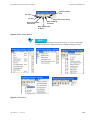


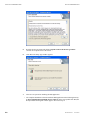
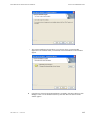
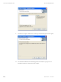

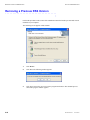
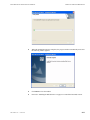

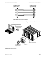
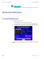
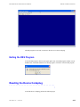
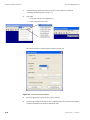
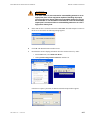

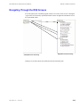
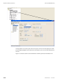
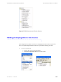


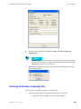
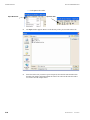
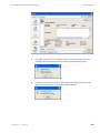


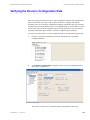


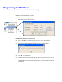
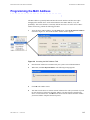
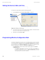
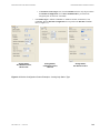
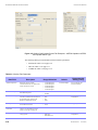


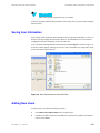
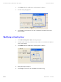
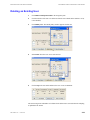
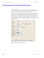
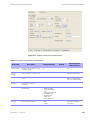
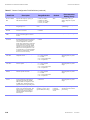
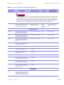
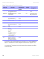
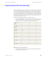
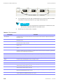
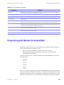

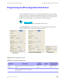
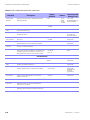

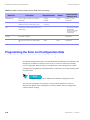
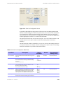
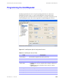
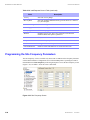
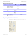
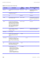
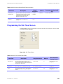
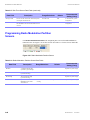

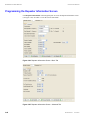
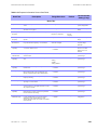

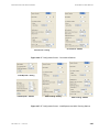
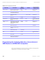
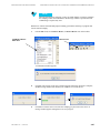
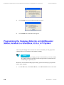

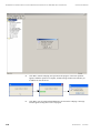
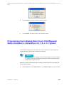
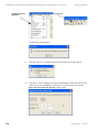
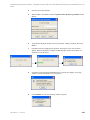
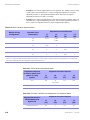
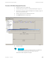
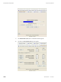


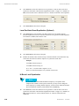


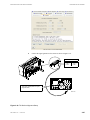
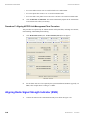
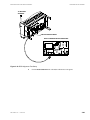
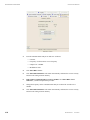
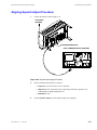
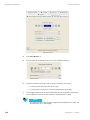


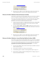
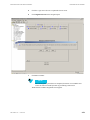
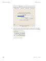

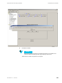


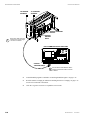
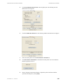
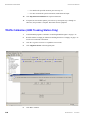
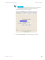

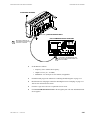


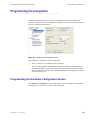

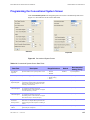
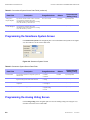

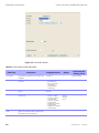
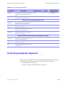
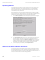
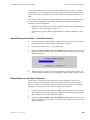

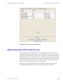
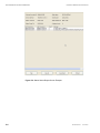
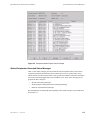
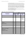
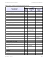


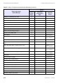

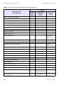
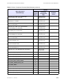


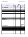


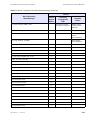

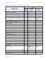
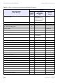
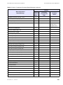
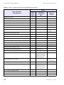
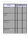

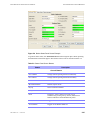


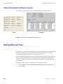
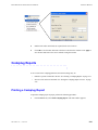
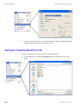
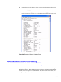


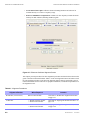

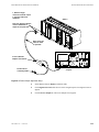
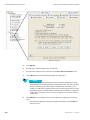

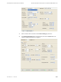
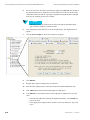
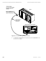
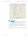
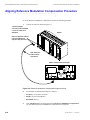
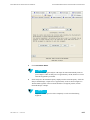
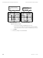


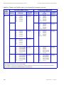


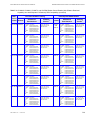
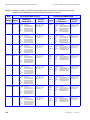
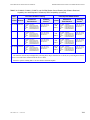
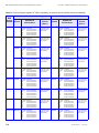


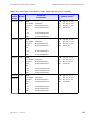
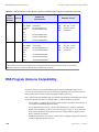


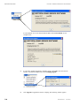
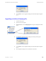

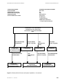
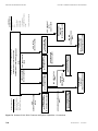


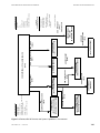
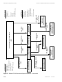

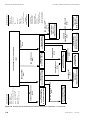

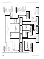


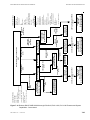
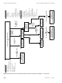

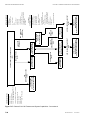
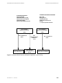

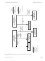

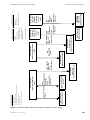
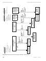
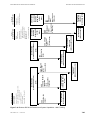

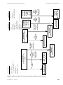
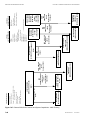


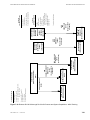
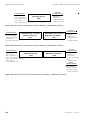

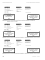
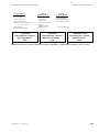


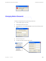
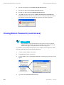
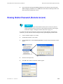
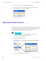


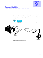

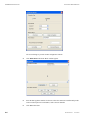
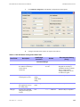
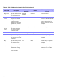
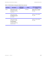


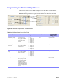


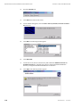
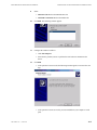
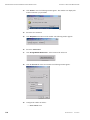
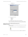

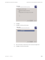
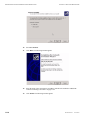

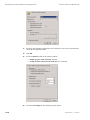

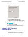

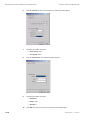

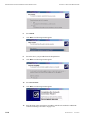
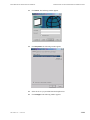
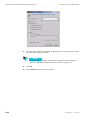


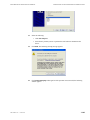

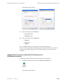
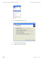
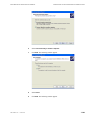

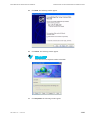
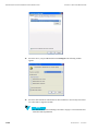


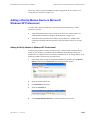
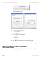
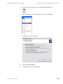


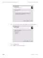

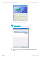


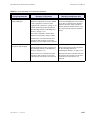
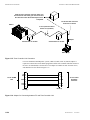
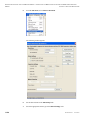
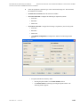
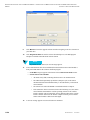
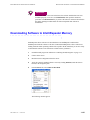


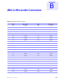


![Hospice Technical Questions & Answers [PDF 114 KB]](http://vs1.manualzilla.com/store/data/005731144_1-513883a519d0031f5bbd9acf18f18865-150x150.png)