1
UniPOS Wireless Fire Alarm Control Panel VIT 01 WIRELESS FIRE ALARM CONTROL PANEL VIT01 INSTRUCTION MANUAL Revision 8/10.13 Instruction manual Revision 8/10.13 Page 1 Pages 50 UniPOS 1. 2. 3. 4. 4.1. 4.2. 4.3. 4.4. 5. 5.1. 5.2. 5.3. 6. 6.1. 6.2. 6.3. 7. 7.1 7.2. 7.3. 8. 8.1. 8.2. 8.3. 9. 9.1. 9.2. 9.3. 10. 10.1. 10.2. 10.3. 11. 11.1. 11.2. 11.3. 11.4. 11.4.1. 11.4.2. 11.4.3. 11.4.4. 12. 12.1. 12.2. 12.3. 12.4. 12.4.1. 12.4.2. 12.4.3. 12.4.4. 13. 14. 15. 16. 17. 17.1. Wireless Fire Alarm Control Panel VIT 01 Contents Terminology................................................................................................................ Technical data............................................................................................................ Contents of delivery.................................................................................................... Installation and setup for operation........................................................................... Defining of the structure of the radio network............................................................. Installation of the Control Panel.................................................................................. Description of inputs and outputs. Mounting peripheral devices................................. Connection power supply........................................................................................... General information………………………………………………………………………… Access levels.............................................................................................................. Means of control and indication.................................................................................. Display and using the buttons..................................................................................... “Duty Mode”................................................................................................................ Description.................................................................................................................. Indication..................................................................................................................... Using the keypad........................................................................................................ “Fire condition”........................................................................................................... Description.................................................................................................................. Indication..................................................................................................................... Using the keypad........................................................................................................ “Fault condition”......................................................................................................... Description.................................................................................................................. Indication..................................................................................................................... Using the keypad........................................................................................................ „Disabled component” ............................................................................................... Description.................................................................................................................. Indication..................................................................................................................... Using the keypad........................................................................................................ “Тest Mode”................................................................................................................ Description.................................................................................................................. Indication..................................................................................................................... Using the keypad........................................................................................................ ”Information and control”............................................................................................. Description.................................................................................................................. Indication..................................................................................................................... Using the keypad........................................................................................................ Using the Menus......................................................................................................... Status.......................................................................................................................... Archives...................................................................................................................... Disabled devices......................................................................................................... Set Up......................................................................................................................... Set Up condition.......................................................................................................... Description.................................................................................................................. Indication..................................................................................................................... Using the keypad........................................................................................................ Using the Menus......................................................................................................... Menu Control Panel.................................................................................................... Menu Zones Set Up.................................................................................................... Menu Registration....................................................................................................... Default parameters…………………………………………………………………………. Labour protection requirements.................................................................................. Fire Control Panel initial Start Up................................................................................ Conditions of operation, storage and transportation................................................... Warranty obligations................................................................................................... Recommendations before final installing of wireless fire alarm system on site……... Checking for other devices working on the same band………………………………... Instruction manual Revision 8/10.13 Page 2 Pages 50 4 5 6 6 6 8 8 11 11 11 12 13 14 14 14 14 15 15 15 16 17 17 17 18 18 18 19 19 19 19 19 20 20 20 20 20 21 21 23 24 24 24 24 24 25 25 26 29 32 41 42 42 42 42 43 43 UniPOS 17.2. 17.3. 17.4. 17.5. 18. Wireless Fire Alarm Control Panel VIT 01 Preliminary radio test………………………………………………………………………. Routers and “parents”……………………………………………………………………… Several steps in building configuration…………………………………………………… Possible reasons of dropping messages between elements in the system…………. Appendixes................................................................................................................. Instruction manual Revision 8/10.13 Page 3 Pages 50 43 43 44 46 47 UniPOS Wireless Fire Alarm Control Panel VIT 01 Introduction Wireless Fire Alarm Control Panel VIT 01 is designed for fire security, management and control of wireless fire alarm devices. The usage of radio communication between the control panel and the fire detectors makes it suitable for installation into premises, where laying cables is unwanted. The Control Panel is designed and produced by the requirements of ЕN 54-2/4 and EN 54-25. The Control Panel operates together with: - automatic fire detectors VIT20, VIT30, VIT60; - manual call point VIT50; - router (controller) VIT02. Basic functional characteristics: setting up of the operating modes and parameters of fire detectors, routers and outputs through a built-in keyboard; control for removed(tampered) fire detector from its base, battery status; control over the level of radio signal of the devices; option for changing parameters of the fire detectors; LCD display for visualization of the operating modes of the system; LED indication for signalization of emergency and extreme situations in the zones and within the whole system; non-volatile archive memory, saving up to 4096 events, indicating the time and the type of the event, and allowing a perfect analysis of the actions of authorized personnel and the possible problems in the process of fire safety of the premise; user friendly test modes for all the system components, providing a total control over the condition of the protected premise; test and choice of 16 different channels to establish radio connection; automatic restoration in fault condition, after the reason, that caused the fault has been removed; built-in serial interface RS232/RS485 for connection with personal computer; different ways possibility of installation designs, within the range of the control panel’s resources. 1. Terminology Addressable point – Detector or manual call point that can be indentified individually by the Control Panel; Fire detector (FD) – a device that monitors the status of one or more input signals and sends a message for fire condition upon certain state of the signal; Router (Controller) - a device which serves to retransmit the signals between the control panel and fire detectors. Each router has one monitored output to signal a fire condition. It can be enabled or disabled in case of faulty. Network ID (PAN) – Identification number of the radio network of the Control Panel. Each network has an unique identification number. Link quality indication – parameter, indicating the radio signal level between fire detector and conotrol panel. The quality of the connection is measured in the range of 0 to 99 %. Output – monitored or relay output. Can be programmed by the user to be activate in case of fire event. Disabled component – fire detector, which is not monitored for fault and fire condition or an output which is not controlled or monitored in case of fire or fault condition. This condition can be set by the user. Indication of a disabled device includes a common light signalisation and text information on the LCD. Monitored output –a potential output, which allows for monitoring the condition of the connected wires between the control panel and the executive device. It requires using a special wiring diagram. Local sounder – built-in into the control panel, activated upon fire condition or fault condition; Access level – access level to various indications and control functions. Fire condition Stage 1 (Fire 1) – fire mode, entered by the control panel upon activation of an automatic fire detector. It will continue until the control panel is reset by manual operation. This fire Instruction manual Revision 8/10.13 Page 4 Pages 50 UniPOS Wireless Fire Alarm Control Panel VIT 01 mode is indicated by common light signalization, local sound signalization and text information on the LCD display. Fire condition Stage 2 (Fire 2) – fire mode, entered by the control panel in two situations: after time Fire 1 – Fire 2 expires; activation of a manual call point VIT50; The phase is indicated by a common light signalization, a local sound signalization and text information on the LCD display. Relay output – relay, potential-free, switching outputs that controls external executive devices. 2. Technical data 2.1. Maximum number of addressable devices / zones per system - 64/15 2.2. Radio network parameters Frequency - 2.4 GHz Maximum number of routers connected to one control panel -6 Maximum number of routers connected in series to one control panel -4 Maximum number of adressable devices (FDs and routers) connected directly to the Control Panel - 20 Maximum number of fire detectors connected to router - 14 2.3. Controllable outputs Type Electrical features - 2 pcs. - potential, relay - (24±5)V DC/1 A 2.4. Relay output for fire condition Type Electrical features - 1 pc. - potential-free, switching - 3A/125VAC; 3A/30VDC 2.5. Relay output for fault condition Type Electrical features - 1 pc. - potential-free, switching - 3A/125VAC; 3A/30VDC 2.6. Indication of the registered events Light indication Text messages - LED - crystal-liquid display – 4 rows, 20 characters per row, cyrillic, back-lit - built-in sounder Sound 2.7. Power supply 2.7.1. Mains power supply - 220/230 VAC/50 Hz 2.7.2. Back up (battery) power supply: battery type - lead, gel electrolyte number of the batteries - 2 pcs connection - serial connection nominal voltage of the connected back up batteries - 24 VDC nominal capacity С20 - (1,2 – 4,5) Ah terminal discharge voltage - 17,6V charge voltage - 28V consumption on the back up battery supply - <180mA at 24V 2.7.3. Fuses mains supply 220/230 V - 4,0 А back up battery supply - 2,0 А 2.8. Overall dimesions - 313х218х85 mm 2.9. Weight (excluding the back up batteries) - 1,440 kg Instruction manual Revision 8/10.13 Page 5 Pages 50 UniPOS Wireless Fire Alarm Control Panel VIT 01 3. Contents of delivery Fire Control Panel VIT 01 Resistors 5,6k/ 0,25W Cable Bridge for the back up batteries Fuse 4A Fuse 2A Instruction Manual and Instructions for the authorised staff on a CD Antenna Transport package - 1 pc. 2 pcs. 1 pc. 1 pc. 1 pc. - 1 pc. - 1 pc. - 1 pc. 4. Installation and set up for operation 4.1. Defining of the structure of the radio network It is necessary before installation to define the structure of the radio network. On fig. 1.1, 1.2 and 1.3 are shown different types of connection. In the first case (fig 1.1), 5 routers (controllers) are connected in series. Fire detectors are additionally connected to 4 of them and to the Control Panel. Fire VIT 01 detectors can not be connected to router (R) 5, due to the limitation – messages between the elements within the system can be retransmitted not more than 5 times. VIT02 No.1 VIT02 No.2 VIT02 No.3 VIT02 No.4 VIT02 No.5 Fig.1.1 Instruction manual Revision 8/10.13 Page 6 Pages 50 UniPOS In the second case (Fig.1.2), 6 routers (controllers) are connected directly to the Control Panel and to each of them (including to the control panel) are joined fire detectors. In this case, the maximum number of retransmissions of messages is 2. Wireless Fire Alarm Control Panel VIT 01 VIT 01 VIT02 No.1 VIT02 No.3 VIT02 No.2 VIT02 No.4 VIT02 No.5 VIT02 No.6 Fig.1.2 In the last case the connection is mixed. Part of fire detectors and the routers are connected directly to the control panel, some of them - to other routers in a hierarchical structure. In cases when the system device range has not reached full capacity, the method for configuration is not essential. Configuration must be build on way that signal strenght is best between elemenents of the network (see 17.2.). Each device in its initial connection is scanning for a Router or for a Control Panel with the best quality connection. Ones detectors find its Control Panel or Router, communication in the future work of the detector will be implemented through a remembered element (Panel or Router) until further actions will be performed. When in the system should be connected maximum number of devices, or close to the maximum devices capacity and the limitation of the connected devices is up to 14 to some panel or R, then the sequence of the initial connection is very important. The method is the following - at any moment there should be only one element which is enabled (a router and a Control Panel) for connection. VIT 01 VIT02 No.1 VIT02 No.4 VIT02 No.2 VIT02 No.5 VIT02 No.3 VIT02 No.6 Fig. 1.3 As an example, consider the establishing of the system in Figure 1.1. In the following order: Connect router1; Disable the connection of other devices,directly to the Control Panel; Connect router2. At this point, it can be connected only through router1, as the only one device, open for new elements; Disable connection of devices to router1; Instruction manual Revision 8/10.13 Page 7 Pages 50 UniPOS Wireless Fire Alarm Control Panel VIT 01 Connect router3 to router2; In the described method above, connect R4 to R3, R5 to R4. In this configuration of the network it is not possible to connect any devices to R5, because limitation of the retransmissions of the messages through routers is 5 (see 2.2.) ; Join fire detectors to router4; Disable the connection to router4 and enable connection to router3; Join the fire detectors of router3; Perform the same procedure with the fire detectors for connection to R3, R2, R1 and the Control Panel. 4.2. Installation of the Control Panel unpack the Control Panel; mount the dowels for fixing the Control Panel onto a specific place; fix the Control Panel to the dowels through the three openings of the box (pos.3, fig.2). Fig.2 4.3. Description of inputs and outputs. Mounting peripheral devices to the Control Panel All accessions are made by means of terminals, mounted on the printed circuit board (pos.4, fig.2). Please note that the consumption of the controllable output should not exceed, 1,0 А in any fire panel mode. “+Out1-”, “+Out2-”–Monitored outputs- relay, potential, the line is monitored for shortcurcuit and for interruption. Outputs are used to manage devices in fire mode of the Control Panel. These outputs are programmable outputs. “GND” – GND terminal. Instruction manual Revision 8/10.13 Page 8 Pages 50 UniPOS Wireless Fire Alarm Control Panel VIT 01 “+28V-” – Terminal for user supply voltage 28V to peripheral devices. “Rel Fire” – Output, relay, potentiial-free, the line’s status is not monitored.The output is used to control devices in fire mode of the Control Panel. “Rel Fault” – Output, relay, potential-free, the line’s status is not monitored. The output is used to control devices in fault condition of the Control Panel. “+28V” – Two terminals for supply voltage +28V to peripheral devices. “RS232/485” – Terminals for connection of two-wire line of interface RS485 or three-wire line for RS232. Switching between interfaces is done by changing position of a jumper on the board. Interface RS232 is used for a connection with a РС. RS485 is intended for a connection between different Control Panels VIT01 (this functionality is not available in the current version of the Control Panel). There is a jumper provided, which terminates the line with resistor 120 upon mounting. This is necessary if the Control Panel is the endpoint of the interface line. The interface requires both ends of the line to be terminated with resistors 120. “┴” – Terminal for connection of a third wire / shield / on the interface cable. Fig.3 4.3.1. Description and mounting of devices to output “Rel Fire” Output “Rel Fire” is a relay output with potential-free contacts, situated on the terminal bus: Instruction manual Revision 8/10.13 Page 9 Pages 50 UniPOS Wireless Fire Alarm Control Panel VIT 01 – normally open “NO”; – normally closed ”NC”; – common point “С”. In Duty Mode there is a contact between terminals “C” and “NС” of the relay. In Fire condition, there is a contact between terminals “C” and “NO” of the relay. The output is not monitored for short-curcuit or interruption. The relay contacts do not commutate 220V! 4.3.2. Description and mounting of devices to output “Rel Fault” Output “REL Fault” is a relay output with potential-free contacts, situated on the bus terminal: – normally open “NO”; – normally closed ”NC”; – common point “C”. The output is activated in Fault condition. In Duty Mode there is a contact between terminals “C” and “NO” of the relay. In Fault condition, there is a contact between terminals “C” and “NC” of the relay i.e. an output device, commutated through the contacts of “REL Fault” will signal for fault condition in the system. The output is not monitored for short-curcuit or interruption. The relay contacts do not commutate 220V! 4.3.3. Monitored outputs “Out1” and “Out2” Outputs are connecten on two-wire line for connection with the devices for sound and light signalization. The line is trimmed and monitored for interruption and for short-circuit. In order to control the condition, it is necessary on the terminals of the signaling device to place resistor 5.6 к / 0.25W. 5,6 k - Out x + On activation the monitored outputs supply voltage (24±5) V. Maximum current load of the output is 1А. Outputs are programmable and can be activated in Fire mode. In case of short circuit between “+” and “-“ the output activation will be disabled. 4.3.4. Description and installation of devices to terminals of interface RS232/RS485 Interface RS232/485 is used for connection between the Control Panel and other intelligent devices and PCs. The connection between devices on RS485 is done by parallel connecting on two-wire line observing the requirement, potential "A" and "B” should not be crossed. The maximum distance between the final devices is 1000 m. Regardless of the length of the line, on the first and on the last device, it is necessary to put the jumper for line termination with 120. For all other devices, the jumper must be removed. For connection of the Control Panel with the devices on RS232 we use three-wire line – RX, TX and GND. The signal lines RX and TX connecting the panel and the other device should be crossed. The so-called "NULL modem" cable is suitable for this conneciton. The maximum distance between the Control Panel and the other device is 15 meters. In this case, communication is “point to point”. Instruction manual Revision 8/10.13 Page 10 Pages 50 UniPOS Wireless Fire Alarm Control Panel VIT 01 4.4. Connecting power supply Connect power cable to the terminal (pos.1, fig.2) with fuse (pos.2, fig.2), observing the following location: - L – feeding wire “Phase”; - N – feeding wire “Null”; - “Ground” – safety ground wire. The cable must be double insulated, with cross section not less than 0,5 mm2 for the feeding wires, and 1,5 mm2 for the safety ground wire. Connect the other end of the feeding cable to the mains, using a junction box. Mains power supply of the Control Panel should be on a separate circuit. 5. General information 5.1. Access levels There are four access levels in the Control Panel: 5.1.1. Access level 1 These are the access levels for all persons who are intended to find out and react initially on the signalizations for fire condition or/and fault condition. The personnel with Access level 1 shall be trained and authorized to operate with the Control Panel in conditions Duty Mode, Fault condition, and Disabled component. In access level 1 the following features are available: - displaying suppressed messages for fire condition,fault condition or disabled component; - start inspection time period; - suppressing the local sounder. All light indications of the Control Panel are visible. 5.1.2. Access level 2 – Default password - 0000 Two actions lead the operator to Access level 2: - unlock and open the front cover of the Control Panel (part of the actions); - enter password for access level 2 or 3. In access level 2 the following features are available: - all accessable features of Access level 1; - reconfiguration specific data of the Control Panel; - replacing a burnt fuse; - connecting of output devices; - suppressing and re-activation of the fire alarm outputs; - setting up and excluding a zone in „Test”; - activating all the outputs within the system („Evacuation”); - testing or disabling the system outputs; - LED test of all LEDs on the panel; - Setting date and time; - Changing language of the panel’s menus; - resetting fire condition. 5.1.3. Access level 3 – Default password 1111 Two actions lead the operator to Access level 3: - unlock and open the front cover of the Control Panel (part of the actions); - enter password for Access level 3. The following features are accessible: - all accessable features of Access level 2; - entering and changing password for Access level 2 and level 3; - deleting the archive; Instruction manual Revision 8/10.13 Page 11 Pages 50 UniPOS Wireless Fire Alarm Control Panel VIT 01 - registration, exchange and exclusion of addressable points in the radio network; changing the parameters of the addressable points and zones. 5.1.4. Access level 4 Accessible for personnel, trained and authorized by the producer to dismantle the fire control panel and to modify the software. Special means are required for access this level. 5.2. Means of control and indication Wireless Fire Control Panel VIT01 operates in seven basic conditions: Duty Mode, Fire condition mode, Fault condition mode, Disabled component mode, Test mode, Information and control mode and Set Up mode. At any moment, the control panel can be in one of them or in random combination of modes: Fire condition, Fault condition, Disabled component, Test and Information and control. The condition Set Up can not be combined with another condition. Entering Set Up condition exits all the other conditions. The Control Panel conditions and their corresponding indications are described in Table 1. Table 1 Condition of the Fire Control Panel Indication All conditions The fire control panel is power supplied Indicator Power supply – continuous green light Fire condition Phase 1 – inspection time is entered Indicator „Time Delay” – continuous yellow light (if time delay is set) Duty Mode, Fault condition, Information and controldisabled components are available Indicator „Disabled component” – in case of disabled component Duty Mode, Fault condition, Disabled component, Information and control – Test Mode Indicator Test Fire condition Common indicator “Fire condition” - red light in combination with the individual indicator of the zone, where the fire condition has been registered. Fault condition All fault conditions, excluding low power Common indicator “Fault condition” - continuous yellow light Fault condition – System fault Indicator “System fault” continuous yellow light Fault condition Indicator “Fault in Power supply” continuous yellow light Fault condition Indicator “Fault in a monitored output” - continuous yellow light Fire condition Local sounder- discontinuous signal – fast beeping Fault condition Local sounder - discontinuous signal – slow beeping Instruction manual Revision 8/10.13 Page 12 Pages 50 UniPOS Wireless Fire Alarm Control Panel VIT 01 Table 2 Means of control Condition of the Control Panel Button “Reset” Fire condition Button “Outputs” Fire condition Access Lecel Levels 2 and 3 Reset Fire condition Stage 1 or Fire condition Stage 2, indicated on the display Levels 2 and 3 - In presence of activated outputs for Fire condition – suppresses the outputs; - In suppressed outputs for Fire condition – reactivates the outputs Forced outputs activation – Evacuation (see 6.3 - Note) Duty Mode Button “Alarm” Button “Menu” Button „Down” Button “Up” Button „End” Fire condition or Fault All condition Duty Mode, Fire condition, Fault condition, Test and Disabled component Set Up, Fire condition, Fault condition, Test and Disabled component Set Up, Fire condition, Fault condition, Test and Disabled component Set Up, Fire condition, Fault condition, Test and Disabled component Suppressing/ activating of the local sounder All - Enter next menu; - Confirm data; - Next position. Levels 2 and 3 - Selects next basic screen; - Moves the cursor through menus; - Selects next parameter. Levels 2 and 3 - Selects the next screen; - Moves the cursor through menus; - Selects next parameter. Levels 2 and 3 Returns to the previous screen All Adds additionally set inspection time for each activated zone between phase 1 and 2. Button „Inspection” Fire condition Operation 5.3. Display and using the buttons 5.3.1. Display The LCD display shows three types of information: basic screens; menus; entering parameters. The basic screens display information about the system status or the condition of one of its components, as well as event log information about past events in the system. The menus display different options for selecting function or submenu. The cursor is a flashing rectangle and it moves along the row of buttons and . On the screens for entering parameters are given the parameter name and to what part of the system is related. The cursor is a line below the changing value. 5.3.2. Using the buttons For operating the Control Panel are used 8 buttons, as 4 of them are with unique functions in mode „Fire condition”, and the rest are used in the context of the displayed information, namely: Menu/ Confirmation Instruction manual Revision 8/10.13 : Page 13 Pages 50 UniPOS Wireless Fire Alarm Control Panel VIT 01 o o o In the main screen – selects menu for possible functions; In the screen with menu – confirms the function, selected by the cursor. In the screen for changing the parameter – confirms the entered value and selects the next in the line. For some parameters as names and passwords, the button moves the cursor on the next digit or character. Holding the button for more than 1 second completes the operation on entering parameters and proceeds to the next submenu. Vertical arrows and : o In the main screen – select next main screen; o In the screen with menu – move the cursor up and over the elements of the menu; o In the screen for changing the parameter – increase and decrease the current value of the selected parameter. Holding the button for more than 1 second changes the values with high speed. Exit : o In the screen of submenu and screen with menu – returns the dispay to the previous main screen; o In the screen for changing the parameter – records the changes of the parameters (if changes were made) and returns the display to the previous main screen; Diagram of the screens and menus of the Control Panel is shown in Appendix 2. 6. Duty Mode 6.1. Description The Fire Control Panel is in Duty Mode, when it is not in any other modes. 6.2. Indication 6.2.1. LED and sound indication In this conditionis is illuminated only the green LED indicator LED indicator The indicator „Test” (“Power Supply”). The yellow („Disabled component”) – is illuminated only if there are disabled components. is illuminated if there is a zone set in test. Local sounder is swiched off. 6.2.2. Text indication The display shows the following information: - Condition of the Control Panel (Duty); - Real time; - Weekday; - Current date; 6.3. Using the keypad The only one active button at that condition is (“Menu”). The button is accessable for all the Access Levels. Information about the status of devices, outputs, zones and Control Panel is available at all access levels. Instruction manual Revision 8/10.13 Page 14 Pages 50 UniPOS Wireless Fire Alarm Control Panel VIT 01 Note: In „Duty Mode” the outputs of the Control Panel and the connected to it routers can be forced to activate by pressing button the text „Evacuation”. at access level 2 or higher. In this case the display shows 7. Fire condition 7.1. Description The Fire Control Panel enters Fire condition mode upon activation of a fire detector of the system. Exit from this mode is only through manual operation – pressing button or 3 password. with access level 2 7.2. Indication 7.2.1. LED and sound indication In this condition are illuminated: (“Power supply”); - With green light indicator - With red light indicator (“Fire condition”); With red light the indicator of the relevant zone - If the outputs for fire condition are suppressed by button indicator of the button is illuminated in continuous red light; - If the sound indication is suppressed by button button is illuminated in continuous red light. ; (“Outputs”), the LED (“Alarm”), the LED indicator of the The local sounder produces a discontinuos signal – fast beeping. 7.2.2. Text indication In this condition the display is divided into two text fields: On the first and on the second line it is displayed information about: - Number of fire; - The fire detector in fire condition (if it is only one); - The first fire detector, reported a signal for fire condition (if there are more than one signals for fire) On the 3rd and 4th line: it is duplicated information about the fire detector in fire condition (of only one); it is displayed information about the last activated fire (if more than one) and its number. The following information is visuslized on the display: On the first line: - Number of fire (Example: 01); - The Phase of the Fire condition (Example: Fire1); - Address and user description name of the fire detector (Example: 17 Room 15); On the second line: - Number and user description name of the zone (Example: 01 Floor1) to which detector belongs; - At phase 1 – the time in seconds, remaining to entering phase 2 (Example: 33). Instruction manual Revision 8/10.13 Page 15 Pages 50 UniPOS Wireless Fire Alarm Control Panel VIT 01 On the 3rd and 4th line – corresponding information about the last activated fire (if they are more than one) or duplicated information from the two lines above (if the activated fire detector is only one). The Control Panel enters „Fire condition 2” after the set time between phase 1 and phase 2 expires. Default time between phase 1 and phase 2 is 60 seconds and can be change from parameters of the zone. Proceeding to „Fire condition 2” is performed immediately in the following cases: the set time Phase1-Phase2 and the inspection time are 0. the fire condition signal comes from FD type VIT50 and parameter „Manual Call point priority” of the zone is set to „Yes”. button is held down more than 5 seconds. 7.3. Using the keypad Actions on using with buttons apply to all the areas, where the fire condition occurs. Button Access Action Additional information Level All Pressing the button : The action of the button is Button (“Alarm”) - switched off the local reversible i.e by single pressing sounder ; changes the current condition - activates the local sounder, respectively – switched off or if the Control Panel has switched on sounder. entered Fire condition or LED indicator is illuminated if Fault condition, and the local the condition switched off sounder was muted by sounder is active. previous pressing of the The local sounder is same button. activated again: - upon entering Fire condition of the Control Panel from a new zone; - in occurance of a new fault or fire. nd 2 or Pressing the button: Operating with the button Button higher suppresses the outputs, requires access level 2 or higher. (“Outputs”) switched off , in case of Fire The action of the button is reversible i.e by single pressing condition; activates the suppressed changes the current condition respectively – suppressed or outputs if there are any; in case the Control Panel is activated outputs. LED indicator is illuminated if in Fire 1, it goes to to Fire 2 if the button was held down the condition suppressed outputs is active. for more than 5 seconds. Instruction manual Revision 8/10.13 Page 16 Pages 50 UniPOS Wireless Fire Alarm Control Panel VIT 01 Button („Inspection”) Button (“Reset”) All Adds Inspection time in the Control If this button is pressed when Panel is in „Fire 1”. the Control Panel is in „Fire 1”, Time is set for each zone. that increases the time period between phase 1 and phase 2 of the occurred fire condition with set inspection time until the Control Panel enters „Fire 2”. nd 2 or Pressing the button forces the Operating with the button higher control panel to exit from Fire requires access level 2 or higher. condition – clears all fires in all zones Button (“Menu”) All Pressing the button enters Check the condition of the condition Information and control. fire detectors and the current fault conditions. Buttons („Up” and „Down”) All If the fire conditions are more than one, information about each of them is displayed by means of the buttons. All Pressing the button leads to exit from the condition Information and control. The main screen in the current Fire condition is visualized. и Button (“Exit”) 8. Fault condition 8.1. Description The Fire Control Panel enters „Fault Condition” upon detecting fault in one of the modules or/and in one of the devices, registered within the system; A list of possible faults is given in Appendix 2. 8.2. Indication 8.2.1. LED and sound indication For all fault conditions, indicator (“Fault”) is on with continuous yellow light. Depending on the type of the fault condition, the following indicators are also illuminated: In system fault - indicator (“System fault”) with continuous yellow light; fault in a controllable output - indicator output”) with flashing yellow light; (“Fault short-circuit or an interrupted controllable in fault of the mains or back up batteries supply - indicator (“Fault Power supply”)is illuminated with continuous yellow light; in fault in any of the fire detectors, the indicator of the zone, to which it belongs is illuminated in flashing yellow light. The local sounder is activated and produces discontinuous signal. In case the sound signalization is suppressed by button light. (“Alarm”), the LED indicator of the button is illuminated in continuous red 8.2.2.Text indication The screens of fatal faults suppress all other messages. In the occurance of more then one nonfatal faults, they are indicated by their time of appearing. Last fault is indicated on the display. Instruction manual Revision 8/10.13 Page 17 Pages 50 UniPOS Wireless Fire Alarm Control Panel VIT 01 Upon registering of fault condition, relay „REL Fault” is activated. Entering Fire condition of Control Panel suppresses the messages of fault condition. The display shows information about the type of the fault and the total number of faults. (Example: Fault in the Back up batteries supply. Total number of faults – 2. The common indicator for fault condition is illuminated , the specialized indicator and the local indicator for fault conditionin zone 7.The second fault can be reviewed by using buttons “Up” and “Down”). 8.3. Using the keypad There are no active buttons in fatal fault condition. For the other fault conditions are used 4 active buttons. When the Fire Control Panel is in a combination with other conditions are active their corresponding buttons. Button Access Action Additional information Level All Pressing the button: The action of the button is Button - switches off the local reversible i.e by single pressing (“Alarm”) sounder; changes the current condition - activates the local sounder, respectively – switched off or if the Control Panel has switched on sounder. entered Fire or Fault The LED indicator is condition, and the local illuminated if the condition sounder was switched off by switched off sounder is active. previous pressing of this The local sounder is button. activated again: - upon entering Fire condition of the Control Panel; - in occurance of a new fault or fire. All Display information about fault Buttons („Up” conditions, if more than one fault is and „Down”) registered. и Button (“Menu”) All Pressing the button Information and control. enters Check the condition of the fire detectors and the current fault conditions. 9. Disabled component condition 9.1. Description The Fire Control Panel enters Disabled component condition after manual operation of disabling an element of the Fire alarm system – a fire detector or a routers (controller). Operations for disabling shall be performed in Set Up mode at access level 2 or higher. Upon disabling an output, it can not be activated in any circumstances and it is not monitored for fault condition. Operations on disabling elements are described in “Set Up” condition. Instruction manual Revision 8/10.13 Page 18 Pages 50 UniPOS Wireless Fire Alarm Control Panel VIT 01 9.2. Indication 9.2.1. LED and sound indication In presence of a disabled component, indicator The condition has no sound indication. is continuously on 9.2.2. Text indication The entered disabled components can be reviewed from condition Information and control of the Control Panel: - upon selecting „Disabled Devices” the disabled elements are visualized; - General information about the number of the disabled devices is provided in menu „Status/Outputs”, „Status/Zones” and „Status/ Panel”. The position of the flashing cursor „█„ is displayed with highlighted first character of the chapter in the menu. 9.3. Using the keypad Button Access Action Level All Pressing the button enters Button condition information and control. All (“Menu”) the disabled components can be reviewed from menu „Disabled Devices” Additional information Using the buttons in condition Information and control is described in details in chapter 11 and 12. 10. Test condition 10.1. Description The Fire Control Panel eneters Test condition by a specific zone after manual operation for seting a zone in test. The condition can be controlled from Information and control menus after entering a password for access. Enter menu „Status/Zones”to start the test. 10.2. Indication 10.2.1. LED and sound indication The condition has no specific sound indication. LED corresponding zone in test are illuminated. 10.2.2. Text indication In transition to menu Status/Zones a start test window is displayed. Enter access password. Instruction manual Revision 8/10.13 and the LED indicator of the Page 19 Pages 50 UniPOS Wireless Fire Alarm Control Panel VIT 01 The zone is set to Test mode. The display shows information about: - Zone number in test; - Zone mode; - Number of detectors in Fire condition; - Number of Disabled components; - Number of detectors in Fault condition. Exit of the condition is to be performed by the same way, as in the menu „Start Test” is changed with „Stop Test”. 10.3. Using the keypad Active buttons are: - buttons and for zone selection and inserting the digits of the password; - button to enter menu test and confirmation of the inserted password; - button for exit. 11. Information and control condition 11.1. Description Information and control condition mode, through the system of main menus and submenus, provide opportunity to have information about the Control Panel’s settings and control some features of the system components. This condition can operate in combination with the following modes of the Control: - Duty Mode; - Fire Condition; - Disabled component mode; - Test mode; - Fault condition mode; - Set Up mode. 11.2. Indication 11.2.1. LED and sound indication There is no specific LED or sound indication in the this condition of the panel. 11.2.2. Text indication The screens, showing on the display are organized in tree structure of subordinated one to the other menus (Appendix 2). Each screen has a specific text indication, connected to the actions, performed in it. The specific messages are described in the relevant screens. 11.3. Using the keypad Press button to enter condition Information and control from the windows of Duty Mode, Fire condition, Fault condition, Test and Disabled component, which suppresses their text messages. When the Control Panel is in combination of Information and control and Fault condition, button (“Alarm”) is also active. When the Control Panel is in combination of Information and control and Fire condition, the active buttons are (“Alarm”) and (“Outputs”). For operation with this mode are used 4 buttons: Instruction manual Revision 8/10.13 Page 20 Pages 50 UniPOS Wireless Fire Alarm Control Panel VIT 01 Menu/Confirmation : o In the main screen – selects menu for possible functions; o In screen with menu – confirms the function, selected by the cursor. Navigation buttons and : o In the main screen – select next main screen; o In a screen with menu – move the cursor up and down over the elements of the menu; o In screen for changing the parameter – increase and decrease the current value of the selected parameter. Holding down the button for more than 1 sec changes the values with high speed. End : o In the screen of submenu and screen with menu – returns the dispay to the previous main screen; In the screen for changing the parameter – records the changes of the parameters (if changes were made) and returns the display to the previous main screen. o 11.4. Using the menus Upon entering condition Information and control is realized transition to menu. It consists of the following subordinated menus: - Status; - Archives; - Disabled devices; - Set Up. Active buttons: , , and . 11.4.1. Menu “Status” The menu consists of information for the status of: Detectors; Outputs; Zones; Panel. 11.4.1.1. „Status/Detectors” Shows the status of the fire detectors in the system. The first line displays the addressand the type of the selected FD. The second – the symbol sequence (the name) and the zone, where it is situated defined by the user. The third line shows its current status and mode of operation. Active buttons: , and . Meanings of the positions in field ‘’Status’’ is explained in 12.4.3.2. Instruction manual Revision 8/10.13 Page 21 Pages 50 UniPOS Wireless Fire Alarm Control Panel VIT 01 11.4.1.2. „Status/Outputs” The status of the outputs in the system is shown. On the second line is shown the name of the output („Output1”, „Output2” for the monitored outputs of the Control Panel or the symbol sequence (the address and name) of the router (controller), managing the output). The current condition of the output is also shown. Possible conditions are: Off – normal ; On - switched on; Dis – the output is disabled and does not activate upon fire condition or test; Fault – for controllable outputs – interrupted or short-circuit of the output. For the outputs of the routers – fault in the router (controller); Init – the router, responsible for the output is not in the network. Active buttons are: - buttons and for previewing the status of all outputs. The conditions of output 1, output 2 are shown consecutively, and if there are routers, registered in the network, the conditions of their outputs are also shown; - button returns the display into the main window. 11.4.1.3. „Status/Zones” Displays the status of zones in a table: For each zone are shown the total numer of connected fire detectors, the number of the disabled ones and the detectors in fault. Use button to enter menu for setting a zone in test or to review the condition of the fire detectors. Setting and excluding a zone in test shall be performed by access level 2 or 3. The indicator of the zone in test is lit on. Also the common indicator of the Control Panel „Test” is lit. Active buttons are: , , and for each zone. 11.4.1.4. “Status/ Panel” The general status of the Control Panel is shown in a table, corresponding to the condition of the zones. On the last line are shown the total number of the registered outputs and their condition, including the controllable outputs of the panel. Instruction manual Revision 8/10.13 Page 22 Pages 50 UniPOS Wireless Fire Alarm Control Panel VIT 01 Button („Menu”) alternatively shows the general information about the records in the archive of the Control Panel. Avrive buttons are and . 11.4.2. Submenu “Archives” The menu is accessable at Access Level 1 and contains information windows with event records. The Control Panel supports an archive of maximum 4096 records. Each record contains information about the event, the real time and time of its occurance. Records are devided into three main groups: Records for fire condition; Records for fault condition; All records. In Appendix 3 is given a list of all possible records, contained in the archive. Active buttons: , , and . Use buttons and to select the list for reviewing and button record (the last one by occurance). displays the first The first line of the display shows the number of event according its occuarance (and the name of the record. Last events are presented first. On the second line is displayed – real time of occurance, and on the third line – the event; Buttons and records from the list descending order. Buttons and into the main window. Instruction manual Revision 8/10.13 in are displaying the ascending and return the display Page 23 Pages 50 UniPOS Wireless Fire Alarm Control Panel VIT 01 11.4.3. Menu “Disabled Devices List” The menu is available at all access levels and contains information screens showing the disabled devices in the system. Buttons disabled devices button and display the in ascending order, and - in descending order. Button main window. returns the display into the 11.4.4. Menu “Set Up” Enter „Set Up” mode by entering a valid password. The manu contains screens for setting up parameters of the system and check of the elements of the Fire Alarm System. The Control Panel recognizes 2 valid passwords – of level 2 and level 3. Upon entering password of level 2, part of the mode functions are not accessable for the opertator. Enter the password by following order: By buttons and digit of the password. enter the first By means of button proceed to the next digit. Enter the other digits by the same procedure. The password validity is checked after entering the last digit. Upon entering a correct password the Control Panel goes to to „Set Up” mode. 12. Set Up condition 12.1. Description In Set Up mode shall be performed all the functions on testing, correction of parameters, configuration and changing elelemts of the system. The mode consists of 3 main sections, serviced through a system of menus with a tree structure. (Appendix 2): set up and test of the Control Panel; configuration and setting the basic parameters of the serviced zones; registration, test and set up of the connected in the system elements (routers and fire detectors). Important: In „Set Up” condition the Control Panel does not service fire detectors for fire and fault, and does not activate outputs. 12.2. Indication 12.2.1. LED and sound indication In „Set Up” condition is illuminated only the green LED indicator for the Control Panel’s power supply . The local sounder is switched off. 12.2.2. Text indication Instruction manual Revision 8/10.13 Page 24 Pages 50 UniPOS Wireless Fire Alarm Control Panel VIT 01 The displayed text indication is specific for each menu, function, or screen. In section description of operation in menu "Set Up" are given screens with text indication for each of the adjusted parameters. 12.3. Using the keypad „Set Up” condition is with access level 2 or 3. The Control Panel recognizes 2 valid passwords – of level 2 and level 3. Upon entering password of level 2, part of the mode functions are not accessable for the operator. Enter the password by following order: By buttons and digit of the password; By means of button next digit. enter the first proceed to the 12.4. Using the menus The menu has the following submenus: Note: Menus with italic and bold type are accessible only with password in access level 3. All others are accessable in access level 2. Panel (chapter 12.4.1) Test (chapter 12.4.1.1) Outputs (chapter 12.4.1.1.1) Indication (chapter 12.4.1.1.2) Clock (chapter 12.4.1.2) Parameters (chapter 12.4.1.3) Language (chapter 12.4.1.3.1) Ground check (chapter 12.4.1.3.2) Netrwork address (chapter 12.4.1.3.3) Password access level 2 (chapter. 12.4.1.3.4) Password access level 3 (chapter.12.4.1.3.5) Delete Archive (chapter.12.4.1.4) Zones (chapter 12.4.2) Devices list (chapter 12.4.2.1) Parameters (chapter 12.4.2.2) Name of the zone (chapter 12.4.2.2.1) Inspection time (chapter 12.4.2.2.2) Time Phase1-Phase2 (chapter 12.4.2.2.3) Manual call point priority button (chapter 12.4.2.2.4) Output devices Phase 1 (chapter 12.4.2.3) Output devices Phase 2 (chapter 12.4.2.4) Registration (chapter 12.4.3) Menu permissions (chapter 12.4.3.1) Devices (chapter 12.4.3.2) Instruction manual Revision 8/10.13 Page 25 Pages 50 UniPOS Wireless Fire Alarm Control Panel VIT 01 12.4.1. Menu Panel The menu includes functions for visualization and adjustment of the Control Panel’s elements: outputs and inputs, clock, language of the menus, ground check validity, network address and others. 12.4.1.1. Submenu "Test" 12.4.1.1.1. ‘’Outputs’’ - shows the status of the outputs of the Control Panel. Buttons and show the condition of the monitor outputs, the outputs of the routers and and the monitor inputs. The condition and the mode of the selected output can be changed alternatively by button . If the output is disabled, commands for activating the output are ignored. The indicator for a disabled component illuminates. The output can be enabled by pressing the button again Instruction manual Revision 8/10.13 . Page 26 Pages 50 UniPOS Wireless Fire Alarm Control Panel VIT 01 Test switching on/switching off of the outputs can be done by the second element of the menu for testing outputs. The outputs are displayed by the following order: Monitor output 1; Monitor output 2; The outputs of the routers (controllers) in ascending order of registration. The last window of the test indicates the condition of the following voltages in the Control Panel: For the normal operation of the system, parameters must have the following parameters: Monitored outputs 1 and 2 – 180 to 800; Supply voltage 220V – more than 150; Output user supply 28V – more than 450; Ground – 80 to 500; Back up batteries supply – more than 625; If any of the parameters is not in the limits, the status filed on the first line displays the corresponding index: B – back up batteries supply; E – ground; H – Monitor output 2 is shorted; L – Monitor output 2 interrupted; h – Monitor output 1 shorted; l – Monitor output 1 interrupted; D – Fault in the output supply 28V; A – Fault 220V supply. 12.4.1.1.2. ‘’Indication’’- this option will perform test of the local sound indication and all LEDs supported by the Control Panel. On the display is shown the message ‘’TEST INDICATION!’’ and all LEDs must be switched on except ‘’System fault’’ indicator. Duration of the test is about 15 seconds. 12.4.1.2. Menu „Setting the clock” The menu allows for setting the hour, minute, weekday, month and a year. By button select the parameter for setting. Buttons and are increasing or decreasing the selected parameter. Holding down button completes the setting, without the need to pass through all the settable elements. At the end of the setting, the seconds of the clock are reset and the new real time starts from the beginning of the minute. 12.4.1.3. Menu „Control Panel Parameters” The submenu includes adjustment of the following parameters of the Control Panel: Language ( chapter 12.4.1.3.1); Ground check ( chapter 12.4.1.3.2); Instruction manual Revision 8/10.13 Page 27 Pages 50 UniPOS Wireless Fire Alarm Control Panel VIT 01 Network address ( chapter 12.4.1.3.3); Password for access level 2 (chapter 12.4.1.3.4). Password for access level 3 (chapter 12.4.1.3.5). 12.4.1.3.1. „Language” In this screen define the language, in which the information will be displayed. Information may be in Bulgarian, English or Italian, as a displayed text message. Buttons and parameter alternatively. Possible values: Български; English; Italiano. Press button are changing the to proceed to the next parameter. 12.4.1.3.2. „Ground check” Enables or disables the monitoring of fault „ground”. Buttons and parameter alternatively. Possible values: Yes; No. Press button parameter. change the to move to the next 12.4.1.3.3. „Network address” The parameter defines the address of the Control Panel for connection with other devices trough RS485 interface. The cursor is positioned on the first digit. Buttons parameter. and are changing the Press button to move to the next digit. Enter the four digits analogically. The admissible values are between 0000 and 9999. The address is saved and to go to the next parameter after pressing button on the last digit. Holding down the button on a random digit saves the current combination for network address and moves to the next parameter. Instruction manual Revision 8/10.13 Page 28 Pages 50 UniPOS Wireless Fire Alarm Control Panel VIT 01 12.4.1.3.4. „Password for access level 2” Changing the password of level 2 can be done only, if upon entering „Set Up” mode was entered password for level 3. The cursor is positioned on the first digit. Buttons parameter. and are changing the Press button to move to the next digit. Holding down the button on a random digit saves the entered password and exit. 12.4.1.3.5. „Password for access level 3” Changing the password of level 3 can be done only, if upon entering „Set Up” mode was entered password for level 3. The cursor is positioned on the first digit. Buttons parameter. and are changing the Press button to move to the next digit. Holding down the button on a random digit saves the entered password and exit. 12.4.1.4. „Delete Archive” The function is used for delete the archive. Press button to delete the archive. Message „Archive Deleted” is displayed. 12.4.2. Zones Set Up The zone represents a number of fire detectors, grouped by a certain sign (usually the location) For example: Fire detectors on one floor in a building could belong to one zone Setting a specific zone determines the way of reaction of the system in case of fire alarm in that zone (which outputs of the Control Panel will be activated). The belonging of a detector to a zone should be set in the parameters settings. Zone description includes: description of the parameters – name, inspection time, time period between phases „Fire 1” and „Fire 2”, and button priority; setting a list of outputs activated inphase „Fire 1”; setting a list of outputs activated in phase „Fire 2”; Upon entering menu "Zones", the display shows basic information about the first zone. Instruction manual Revision 8/10.13 Page 29 Pages 50 UniPOS Wireless Fire Alarm Control Panel VIT 01 The first line displays the number and the name of the zone. The second line displays the number of the outputs in „Fire 1” and „Fire 2”.The last line shows the number of the fire detectors, belonging to that zone. Buttons and are displaying information about the other zones in ascending and in descending order. Press button to select the specific zone for setting. The submenu includes information about the fire detectors, connected to the zone which is under setting, the name of the zone, inspection time and other parameters. Press buttons and selection from the submenu. to make a 12.4.2.1. „Check up fire detectors” The screen shows the fire detectors, connected to the zone one by one, providing the following information: line 1 – zone number and zone name; line 3 – address and nameof FD; line 4 – mode and status of FD; Buttons and are displaying information about the fire detectors, connected to the zone in ascending and in descending order Button „Zones”. returns the display in menu 12.4.2.2. „Parameters” The submenu includes setting up of the following parameters of the zone: Zone name; Inspection time; Time period between phases „Fire 1” and „Fire 2” – default 60sec. 0-240sec.; Manual Call Point Priority. Press buttons and to make a selection from the submenu, button display in menu „Zones”. 12.4.2.2.1. Parameter„Zone name” Enter the name character by character. The following buttons are used: buttons and to select the specific character from the set of characters; button - to move to entering the next character of the name; Instruction manual Revision 8/10.13 returns the Page 30 Pages 50 UniPOS Wireless Fire Alarm Control Panel VIT 01 button - to exit in menu „Zones”. The maximum number of characters is 8. After inserting the last character, press button save tha name and proceed to the next parameter. , to Holding down button also saves the introduced name, without the need of entering a maximum number of characters. Depending on the selected language, the possible sets of characters are different: for Bulgarian: _АБВГДЕЖЗИЙКЛМНОПРСТУФХЦЧШЩЪЬЮЯ-9876543210; for English and Italian: _ABCDEFGHIJKLMNOPQRSTUVWXYZ-9876543210; . 12.4.2.2.2. Parameter „Inspection time” The inspection time is additionally added time (in seconds), that the user could activate in order to make a physical check upon released signal for fire condition. Inspection time shall be added to the time period between phases „Fire 1” and „Fire 2”. Active buttons are: buttons and changing the parameter value; button - for saving and moving to the next parameter; for button - to exit menu in „Zones”. The parameter accepts values from 0 to 240. Default value is 0 seconds. 12.4.2.2.3. Parameter „ Time period P1-P2” The parameter sets the time (in seconds) between phases „Fire 1” and „Fire 2”. Active buttons are: buttons and changing the parameter value; button - for saving and moving to the next parameter; for button - to exit menu in „Zones”. The parameter accepts values from 0 to 240. Default value - 60 seconds. 12.4.2.2.4. „Manual Call Point Priority” The parameter determines if upon activation the zone of a manual call point type VIT 50, the panel will directly enter fire phase 2 mode for the zone where the MCP belongs - „Fire 2”. Active buttons are: buttons and - for alternative change of the parameter value („Yes” or „No”); button transition ; Instruction manual Revision 8/10.13 - for saving and Page 31 Pages 50 UniPOS Wireless Fire Alarm Control Panel VIT 01 button -to exit in menu „Zones”. In this case „inspection time” and „ time period phase1-phase2” are ignored. Default value - Manual Call Point Priority is activated. 12.4.2.3. Submenu „Output devices Ph1” In this submenu set the outputs which will be activated in condition „Fire Ph1” of the zone. The outputs within the system are shown consecutively as parameters (Monitored output 1, Monitored output 2 and all outputs of the registered routers (controllers). Each of them must be set with value „Yes” or „No”. Thus there is a completed list of outputs that will be activated in condition „Fire Ph1”. 12.4.2.4. Submenu „Output devices Ph2” In this submenu set the outputs which will be activated in fire condition mode „Fire Ph2” of the zone. The outputs in the system are shown consecutively as parameters (Monitored output 1, Monitored output 2 and all outputs of the registered controllers). Each of them must be set with value „Yes” or „No Thus there is a completed list of outputs that will be activated in condition „Fire Ph2”. Active buttons are: buttons and - for change of the parameter value („Yes” or „No”); button - for saving and transition to next output in the list; button „Zones”. - to exit in menu 12.4.3. Menu „Registration” In the menu are available the following functions: Adding new devices in the system; Removing devices (switching off); Replacing an old device with a new one; Changing the mode of operation of the devices; Disable and enable devices; Changing parameters of the devices. 12.4.3.1. Registration is devided into 2 basic submenus – automatic and manual. Upon the automatic registration, each newly registered device is assigned with a following serial number (address) and it is automatically included within the system. Upon the manual registration, the newly registered device can be added, to replace the previously switched off device, or not to be included in the system. All other functions for setting parameters and changing the modes of the devices are identical. Instruction manual Revision 8/10.13 Page 32 Pages 50 UniPOS Wireless Fire Alarm Control Panel VIT 01 The choice between automatic and manual registration shall be done immediately after entering the menu. The main window of both types is identical: On the first line are described the type of registration and the idenetical code of the radio network. On the second –channel andthe identical code of the last registered device into the system . On the third – the total network status and the mode of connection of the Control Panel. The last line shows the total number of registered devices, those one connected directly to the Control Panel, and the active devices in the network. If there are any disturbances of the normal operation of the system, the field "Status" displays one of the following indexes: N – there is a registered device,which is not in the network (not responding); T – there is a device which is removed from its base; B – there is a device with a low battery; D – there is a contaminated optical-smoke or a combined detector; E – there is a detector with a low back up battery; F – there is a fire detector in Fire condition. Press button „Menu” to open the window for selecting: Enable/Disable connection of devices directly to the Control Panel in the network configuration of the system; Clear network configuration – this option will send command to all detectors in the network to clear its remembered ‘’parent’’ (Control Panel or Router) that they use to communicate with the control panel. After receiving this command, detectors will stop to communicate in the network and will stay in stop mode with blinking all LEDs. After restart of the detectors (removing and restoring its batteries) they will perform new scan for a ‘’parent’’ with best radio link quality. After successful connection detectors will automatically save its new ‘’parent’’. Instruction manual Revision 8/10.13 Page 33 Pages 50 UniPOS Wireless Fire Alarm Control Panel VIT 01 Active buttons are: buttons and - to select a parameter for changing (enabled or disabled registration, changing the type of the registration, or to enter submenu „Channels”); button - to activate the parameter or the submenu and to return to the main screen. button - to exit. Upon selecting submenu „Channels” on the display are indicated 16 radio channels, on which the Control Panel communicates with the fire detectors and the routers. Active buttons are: buttons channel; button - for activating a submenu that includes testing of the channel; button channel and exit and - to select a to confirm new Upon activating the channels test the 16 radio channels are scanned for “noise” activity. The value is given in relative units (00-99), as 00 refers to the free channel and 99, to the fully occupied channel (noise channel). Performing this procedure is compulsory before establishing the network, and it is necessary to be made an evaluation if there are other active devices within the range of the system, and to be selected a channel with no activity. 12.4.3.2. Devices By buttons and of the main screen proceed to test mode and setting up of the devices in the network. For each device, registered in the system it is shown the condition, the measured values and the basic parameters. The first line indicates the number (the address), the type of the device and “parent” in the network. Example: “P:C” means detector with address 03 communicate directly with the (C)ontrol panel (without retransmission of the signal trought routers ). The second line – its identical number and Instruction manual Revision 8/10.13 Page 34 Pages 50 UniPOS Wireless Fire Alarm Control Panel VIT 01 the software version. The third line – the mode of operation and the status. In the status is displayed corresponding index: S – signal „Fire Condition” of optical smoke measurement; T – signal „Fire” of temperature measurement; B – low battery (failed back-up battery supply to the router); P – open detector (failed user supply voltage to the peripheral devices to router); D – normal operation of the measuring system (registration trough this router is enabled); A – signal „Fire condition” by the rise of temperature; X – the measured value is out if the predefined parameters; M – low battery in the back up power source(failed mains supply of router); On the last line are shown the measured values from the device. They are different for the different types and have the following meanings: T – measured temperature; C –smoke concentration; L – quality of the radio connection, as the first number refers to the Control Panel, and a second refers to the end device; S – number of the devices, connected directly to the router; the last value is the voltage of the supplying battery. Active buttons are: buttons button - transition to a menu, describing the device shown; button - exit to menu „Registration”. and - for showing of the registered devices; For each device, the menu (Appendix 2а) includes the following actions: - changing the mode; - user defined name of FD and zone, to which it is connected; - network parameters; - setting up parameters - class, sensitivity, etc. Instruction manual Revision 8/10.13 Page 35 Pages 50 UniPOS Wireless Fire Alarm Control Panel VIT 01 12.4.3.2.1.Submenu „Change Mode” Depending on the type of device the Control Panel shows different menus: Possible functions for the fire detectors are: Disable (Enable); Duty; Service; Switching off. Setting the fire detector into one of the functions, mentioned above has the following effect: o o o o Disable – for all devices. The Control Panel ignores the messages for fault or fire condition from the fire detectors and routers. All activities of transmission of messages and connection continue to operate. Upon a disable command, fire detectors enter „Duty” mode. In case the fire detector is disabled, the submenu „Change Mode” contains only one option - "Enable”. Duty Mode – the fire detector is able to enter “Fire Condition” or „Fault condition” only from this mode. Service mode - for diagnostics and settings of the devices. Unlike the others in this mode the devices maintain a continuous radio connection with the Control Panel and the routers. In this case the battery consumption is very high. Due to that reason, the fire detectors should be kept in that mode for a short period of time. In case no additional actions of the Control Panel are be performed with the service mode detectors, as changing parameters, and monitoring of the measured values, they automatically proceed to “Duty” mode after 1 minute. Switching off – the function disconnects the fire detector from the system. FD no longer communicates with the Control Panel on the radio channel. This function is used during the removing or replacement of devices from the configuration. The routers are with continuous power supply and perform two major functions - to activate outputs in mode "Fire condition" and to retransmit information from fire detectors to the Control Panel and back. For the routers: Disable (Enable); Switching on output (Switching off output); Disable Registration (Enable Registration); Switching off. o Disable –The Control Panel ignores the messages for fault from the routers and does not produce commands for activating the outputs of the routers. All activities of transmission of messages and connection continue to operate. Upon a disable command, the routers switch off their outputs. In case a device is disabled, the submenu „Change Mode” contains only one option - "Enable”. Note: Retransmission function of the router is not deactivated when component is disabled. It still support the main function in the network – to route messages from(to) Control Panel to(from) fire detectors. Instruction manual Revision 8/10.13 Page 36 Pages 50 UniPOS Wireless Fire Alarm Control Panel VIT 01 o Switching on an output (Switching off an output) - This submenu provides the opportunity for their testing and control. Upon selecting Switching on an output (Switching off an output), the Control Panel generates a message for controlling the output of the router. Disable/Enable Registration – manages the connection of new devices to the router. This function does not affect of the operation of the already connected to the router devices; Switching off the router from the mains leads to their disconnection from the system. They no longer communicate with the Control Panel on the radio channel. This function is used during the removing or replacement of routers. Note: This action will cause loosing the communication with all devices which are using this router as “parent” in the wireless network! o o Active buttons are: buttons button - for alternative change of the mode; button - exit to menu „Registration”. and - for selecting function; 12.4.3.2.2.Submenu „Name/Zone” The submenu is used for entering user name of the relevant device. (Ex: „Office1”). For the fire detectors, enter the zone to which they belong. Enter the name by the same way as the zone names, described above. If the device is a fire detector, the introduction of the name and zone shall be made in two stages: - enter the device name (up to 8 characters) Active buttons are: buttons and characher for entering; button - to move to the next character or to a screen for inserting a zone (after the 8th character); button - to select a - exit to „Registration”. - еnter the zone (1-15). Active buttons are: buttons and - to select the number of the zone (1-15); button - to return to the screen for entering the name; button „Registration”. - exit to menu Zone number uniquely determines the location of the detector. The available values of the parameter are from 0 to 15. In values 1 to 15 the fire detector connects to the corresponding zone and upon retransmiting information for fire condition, the Control Panel triggers the appropriate zone indications and assigns the outputs specified in the its description. At value 0 of the parameter, the fire detector does not connect to a specific zone. In this case upon fire condition, the control panel produces only local sound signalization and a “Fire condition” signal without activating additional outputs except mandatory output for activation - relay for “Fire”. If the described device is a router, it shall be described by the procedure above, as only the name requires description (the routers can be selected as addressable outputs for each zone). Instruction manual Revision 8/10.13 Page 37 Pages 50 UniPOS Wireless Fire Alarm Control Panel VIT 01 Note: All fire detectors and manual call points are assigned to Zone 1 with name “ZONE” automatically. Fire detector’s name is predefined to “DETECTOR” , Router’s name to “ROUTER” and Manulal call point ot “MAN. CALL”. In case of fire in Zone 1, both monitored outputs – OUT1 and OUT2 will be activated in Phase 2 without any additional settings from the engineering team! 12.4.3.3.3. Submenu „Network Parameters” Set up the following parameters: Number (Address); Time period of the connection; Response time; Parent. Active buttons are: - buttons - button and - for changing the value of the selected parameter; - to select a parameter; - button - exit to menu „Registration”. Parameter „Device Number” The device number should be assigned in its registration procedure. The numbers are from 1 to 64. The system should not have repeated numbers and all duty is to the operator of the system. Parameter „Contact period” Each device in the system periodically sends a status message to the Control Panel. The parameter sets the interval between two messages (in seconds). This time period does not refer to the reaction of the fire detectors in fire condition. Fire messages are sent immediately upon reaching the criteria for fire. This parameter has informative function for the operator of the system and can not be changed. Parameter „Response time” When sending messages within the system, each device expects a delivery confirmation from the Control Panel. The parameter sets maximum time (in seconds) for receiving confirmation. If after several sending attempts the device does not receive a response, it starts a new procedure for reconnection. Increasing the parameter value may be required for devices that are furthest from the Control Panel (they have 4 or 5 retransmissions of messages through communicational controllers). This parameter has informative function for the operator of the system and can not be Instruction manual Revision 8/10.13 Page 38 Pages 50 UniPOS Wireless Fire Alarm Control Panel VIT 01 changed. Parameter „Parent” This parameter indicates whether the device has saved router or control panel as a device that communicates through the network (so-called device’s “parent”). If parameter is set to “yes”, this means that in cases of events: rejoining the network, in case of complete disintegration and restoration of the network, reboot the device or any other reason in which detector (router) lost regular communication with the panel. Upon restoration of normal operating conditions, device will search only for saved “parent”. If the device does not detect its previous parent, falls into sleep mode and attempting to find it periodically. There are 2 ways to change the “parent” of device: -communication mode – just change parameter to “no”, be sure that device receives the command (parent value “P” will be changed to “0”) and restart device. It will perform new searching for ”parent” and will choose that one to which having best radio link. “Parent” parameter will be automatically set to “yes” after succesfull finding of new parent. -if device lost communication with his parent (“Disconnected” fault is presented for this device), but device is still battery supplied – just change position of the tamper detection button 5 times (see LED indication) and after succesfull operation, the operator will receive an acknowledgement for cleared parent with a fast blinking of all LEDs followed by LED indication corresponding to state “Connection” and searching for new parent. 12.4.3.2.4. Submenu „Measure parameters” Set up the following parameters: Class (for heat and combined fire detectors); Sensitivity (for optical smoke and and combined fire detectors); Measurement period in „Duty Mode”; Measurement period in “Service Mode”; Level „Low battery”; Thermal sensor switched ON (for combined fire detectors); Optical-smoke sensor switched ON (for combined fire detectors). Active buttons are: - buttons - button - to select parameter; - button - exit to menu„Registration”. Instruction manual Revision 8/10.13 and - to change the value of the selected parameter; Page 39 Pages 50 UniPOS Wireless Fire Alarm Control Panel VIT 01 Parameter „Class” The parameter sets the class of the heat fire detectors or the thermal part of the combined FD. Admissible values are : o A1R; o A2R; Parameter „Sensitivity” The parameter sets the sensitivity of the opticalsmoke detectors or the optical smoke sensor of combined FD. Possible values are: o Low ( 0.16db); o Middle (0.18db); o High (0.2db). Parameter „Measurement period in Duty Mode” The parameter sets the interval (in seconds) between the two consecutive measurements of the device. It defines the maximum respond time in case of a fire condition or in case of fault in the devices. This parameter has informative function for the operator of the system and can not be changed. Parameter „Measurement period in Service Mode” The parameter sets the interval (in seconds) between the two consecutive measurements of the device in Service Mode. Parameter „ Low Battery Level” The parameter sets the level, under which, the devices produce a fault signal "Low battery level". Possible range 2.8V – 3.5V. Default value – 3.0V. Instruction manual Revision 8/10.13 Page 40 Pages 50 UniPOS Wireless Fire Alarm Control Panel VIT 01 Parameter „Thermal sensor enabled” The parameter is valid for VIT60. This parameter allows for switching on or switching off part of the combined fire detector. Parameter „Optical-smoke sensor enabled” The parameter is valid for VIT60. This parameter allows for switching on or switching off part of the combined fire detector. 12.4.3.3. Adding This submenu appears upon newly arrived device on the network when the type of registration is manual. By selecting this option, the device registers in the configuration with the next available address. The first line displays the ID of the the new device. 12.4.3.4. Replacing – This submenu is active upon a newly arrived device on the network, when the type of registration is manual. The submenu allows for replacing an existing device that was previously excluded from the configuration, and its occupied address to be appointed to the newly arrived device. The list of the available addresses, can be viewed with buttons and . 12.4.3.5. Deleting - this submenu appears with the newly arrived device on the network when the type of registration is manual. By selecting this option the request for registration of the newly arrived device is rejected. 12.4.4. Default parameters of the control panel VIT01: 1) Remove all power sources from the fire detectors and routers on the site; 1) Go to "Set up" mode; 2) In set-up mode, press and hold the “Reset” button for more than 5 seconds. All records for devices will be deleted and all parameters from the control panel will be set back to default; Instruction manual Revision 8/10.13 Page 41 Pages 50 UniPOS Wireless Fire Alarm Control Panel VIT 01 13. Labour protection requirements The installation and maintenance staff must be well familiar with the equipment’s mechanism and operation, as well as with the common technical safety regulations. Connection to unearthed or to indirectly earthed mains supply is prohibited. Troubleshoots are to be cleared after disconnecting the power cable from the mains supply. The Fire Control Panel is designed for installing in premises with a normal fire hazard, according to current technical standards and regulations. 14. Fire Control Panel Initial Start Up Check up if the mains supply is connected correctly. Check up if the peripheral devices are connected correctly. Place the fuse into the terminals with network fuse, at which all the LED indicators flash up for a short period of time (excluding the system fault) and there appears a message with the Company’s name, the initials of the device and software version. Then the display should show the current time and date. Connect the power cables to the back up batteries, as both back up batteries should be connected consecutively. To the positive lead of the battery join the red wire and to the negative lead - the blue wire. The total voltage of both batteries should be not less than 17,6V, otherwise the Control Panel can not recognize them. Enter Set Up condition and set the parameters of the system. In exit of Set Up condition, the Fire Control Panel enters Duty Mode – the Fire Control Panel is ready for fire security of the premise. 15. Conditions of operation, storage and transportation 15.1. Operation and storage The Fire Control Panel shall operate and be kept into closed premises under the following conditions: 15.1.1. Temperature storage transport operation - from minus 5C up to 35C - from minus 10C up to 50C - from minus 5С up to 40С 15.1.2. Relative humidity resistance storage oprating - up to 80 - up to 93 15.2. Transport The Fire Control Panel shall be transported in closed transport vehicles, and in factory-package and at the mentioned above environment conditions and sinusoidal vibrations with acceleration amplitude с not more than 4,9m/s2 in the frequency range of 10 to 150Hz. 16. Warranty obligations The company manufacturer – guarantees the compliance of the product with EN 54-2/4 and EN 54-25. The warrant period is 18 months from the date of the purchase, providing that: the conditions of the storage and transportation have been observed; the start up has been done by an authorised personnel only; the requirements for operation stated at the Instruction Manual herein have been observed. Instruction manual Revision 8/10.13 Page 42 Pages 50 UniPOS Wireless Fire Alarm Control Panel VIT 01 17. Recommendations before final installing of wireless fire alarm system on site 17.1. Checking for other devices working on the same band 17.1.1. Check for wireless internet routers activity on the site. Working frequency of these devices is 2.4GHz, distributed in 16 different radio channels. Fire alarm system will occupy one of these 16 channels. It is strongly recommended working channels of the internet wireless routers to be different from these one which will be selected for the fire alarm system. For example one wireless internet router type G occupy up to 5 channels (1 to 5 even that its central frequency is set up to channel 3). It's necessary to select free channel or channel with minimum noise level – current state of noise levels on each channel can be obtained performing radio test described in VIT01 Instruction manual - 12.4.3.1. Information about internet routers can be received by the system administrator. You can check occupied channels using free for downloading program “inSSIDer” or similar. 17.1.2. Some internet wireless routers has possibility to change its working channels(hopping between channels or similar). If this option is enabled, must be disabled and working channel to be fixed. Otherwise there is possibility the interenet wireless routers and wilreless fire alarm system to share one frequency channel and this situation can be critical for the communication of the FAS. 17.2. Preliminary radio test 17.2.1. This test must be performed in advance before final installation of the wireless fire alarm system on the site. This test will gives you information about the attenuation of the signal between elements on different floors and on the same floor, but in different rooms where you want to install routers or detectors. This radio test evaluation must be done for each component of the Fire Alarm System *See Instruction manual of VIT30 (General description-"Service mode" and p.2 Evaluation of the signal strength). 17.2.2. Average link quality between elements in the system should be more than 35-40% in both directions. If those levels are lower than 30%, it’s possible messages to be lost from recipient of the message and this cause fault, indicated on the control panel as disconnected device. 17.2.3. When operator sets detector in “Service mode”, its green led going to blink dynamically with a frequency proportional to the radio link quality. If red led of detector starts to blink- link quality is under 30% and installing detector at this radio levels is not reccomendded. In case of stop blinking or static led indication in “Service mode” on the detector – the message from detector has been lost and there is no answer from the panel. If this status continue more than 15 seconds, the radio attenuation between detector and control panel or a router is too high and proper communication can not be established; 17.3. Routers and ‘’parents’’ 17.3.1. One router (or control panel) personally can support up to 14 detectors and it is recommended on each floor to install minimum one router because there is higher attenuation of the signal between floors and this attenuation depends from the materials of which the building is constructed. 17.3.2. There are two methods to join router in the network - with clear parameters and using information about its previous “parent” and personal area network identifier (PAN ID). Instruction manual Revision 8/10.13 Page 43 Pages 50 UniPOS Wireless Fire Alarm Control Panel VIT 01 - Clear parameters – if you want to join router in a new network configuration, without using saved information about previous networks: 1. version 10.12 (see label VIT02 )- it is necessary firstly to switch on router using AC power supply and after that connect additional backup power supply (accumulator); 2. version 12.12 (see label VIT02)- remove the jumper located to the right of the terminal block of the controllable output. Place the jumper again after completion of the accession procedure; Router will scan for suitable “parent” to join and if find such parent (control panel or another router already joined in the network) will send request to join in the network. Ones finished this procedure successfully router will save information for its new “parent” and PAN ID and will use it every time when perform rejoining to a network for some reason. - Using stored information about network – if router has been removed from the network for some reason and want to restored it on the same position in the network: 1. version 10.12 - there are two requirements for successful restorationsaved “parent” is in the network and when start up rejoining router use first backup battery supply (accumulator); 2. version 12.12 – there are two requirements for successful restoration saved “parent” is in the network and jumper located to the right of the terminal block of the controllable output is placed; 17.3.3. When you browsing through detector records in Auto or Manual registration mode, information about router used to retransmit messages to the control panel is presented in the right part of the first line - “P: xx” where XX can be “C” – Control Panel or number which tells you the address in the configurationof the router which becomes as mediator for the communication between detector, routers and control panels. If “P” parameter is zero, this means that the parent for this device is not fixed – select submenu for this detector/“Network par.”/choose “Parent” option and set it to “Yes”. Now the “parent” of this device is saved and its address can be found in “P” parameter. 17.4. Several steps building your ownconfiguration - Set default parameters to your panel – select “Setup/Registration/Auto” and hold “Reset” button for more than 10 seconds. Before that be sure that all wireless fire alarm devices are with removed power sources; - After receiving command for “Default parameters”, Control panel will start general measure of all supported channel (A to P) and will gives you information about current noise for each channel between 00-99%, where 99% means “too noise”. Note that this measurement is accurate only for the moment of measurement and in the communication range of the Control panel. Radio noise for each channel on the 3rd floor for example can be completely differen than the 1st. That why is so important the radio test to be done for all elements in the fire alarm network; - Select working channel of the system, moving cursor using buttons “Up” and “Down” to one of the letters from A to P which is with minimal noise levels. Press “Esc” button to select the channel or “Menu”button to start radio noise measurement again; - Select “Registration/Auto”(chapter 12.4.3 in the VIT01 Instruction manual) - On the display should have "00" devices registered in the configuration, 00 - to the central panel directly and 00 –online; Instruction manual Revision 8/10.13 Page 44 Pages 50 UniPOS Wireless Fire Alarm Control Panel VIT 01 - Be sure that control panel can accept devices directly. Check the status "Enbl: +". If indication is not "+" then enable it using "Menu" button and choose "Enable registration" from the sub menu; - Now switch on your first router C1 and wait to be registered in the configuration of the system. Result should be - "01" devices registered in the configuration, 01 - to the central panel directly and 01 – online; To connect C2 through C1 follow these steps: - Disable direct registration mode of the control panel - according to 12.4.3.1. As a result status "Enbl:" must be "-". - Make sure that C1 can accept new devices - see 12.4.3.2 in the manualparameter “D” from the “St:” field is set (registration trough this router is enabled) must be set; Instruction manual Revision 8/10.13 Page 45 Pages 50 UniPOS Wireless Fire Alarm Control Panel VIT 01 - Using the "Up" and "Down" buttons you must find and display on panel's screen the router's C1 parameters. In this way you will activate the registration mode of the router C1. If letter "D" is presented in the status of C1, means that router can accept new devices through him. If not enabled- press “Menu” button, select "Change mode" and choose "Enable reg.". After successful receiving of the command by the router, status “D” must be set. - To connect C2 through C1 just switch on router C2. We have already prepared the Control panel and C1 in the correct mode. - After successful registration in the main window of the registration menu you will see - "02" devices registered in the configuration, 01 - to the Control panel directly and 02 -online. Which means you already have connected C2 through C1. If you check “P:”parameter of C2, it should be equal to address of C1. In our case – for C1 -“P:C”, C2-“P:01”. - Now you can "Enable registration" of all routers and control panel and follow these steps to connect/register the other devices in the system. These steps will be valid in situation that you have good strength signal between elements that you connect. 17.5. Possible reasons of dropping messages between elements in the system: -big metal structures around devices; -other wireless devices working on the same channel at 2.4GHz band; -specific architecture on the site or materials incorporated in the construction of the building, is possible to have a higher ability to absorbing radio waves. - large distance between components. Average range ensures proper communication between detector and router is 25 m. in open premises. Between router and control panel this range is 100m. UniPOS wishes you a successful work! UniPOS 47, “San Stefano” Str., 5800 Pleven, BULGARIA phone +359 64 891111, +359 64 891 100, fax +359 64 891 110 e-mail: [email protected] Mladost 1, bl.79B, entr.2, ap.17, 1784 Sofia, BULGARIA phone/fax +359 2 9744469, +359 2 9743925 e-mail: [email protected] www.unipos-bg.com Instruction manual Revision 8/10.13 Page 46 Pages 50 UniPOS Wireless Fire Alarm Control Panel VIT 01 18. Appendixes Appendix 1 Front panel VIT 01 1 2 3 4 5 6 7 8 9 10 11 12 13 14 15 16 17 18 19 20 21 Indicator “Fire condition ” Indicator “Fault condition” Indicator “System fault” Indicator “Fault in power supply” Indicator “Fault in monitored output” Indicator “Disabled component” Indicator “Test” Button “Menu” Button “Down” Button “Up” Button “Cancel” Zone indicators for „Fire” and „Fault” Indicator “Power supply” Button “Reset” Button “Delay of the outputs” Indicator “Delay of the outputs” Button “Alarm” with indicator “Suppressed alarm” Indicator “Suppressed alarm” Button “Outputs” Indicator “Suppressed outputs” LCD display (4х20) Instruction manual Revision 8/10.13 Page 47 Pages 50 UniPOS Wireless Fire Alarm Control Panel VIT 01 Appendix 2 Duty mode Detectors (11.4.1.1.) Outputs (11.4.1.2.) Status (11.4.1.) Zones (11.4.1.3.) Panel (11.4.1.4.) Fires Archives (11.4.2.) Faults All Dist.List (11.4.3.) Test (12.4.1.1.) Setup (11.4.4.) Language Clock (12.4.1.2.) Ground check Parameters (12.4.1.3.) Net Address Del.Arch. (12.4.1.4.) Level 2 Pass Panel (12.4.1.) Level 3 Pass Devices list (12.4.2.1.) Name Inspection Time Parameters (12.4.2.2.) Ph1-Ph2 Zones (12.4.2.) Outputs Ph1 (12.4.2.3.) Enable Reg. ManCalPt Prior Disable Reg. Outputs Ph2 (12.4.2.4.) Auto/Manual Reg. Auto Menu Manual Devices Channels Registration (12.4.3.) Instruction manual Revision 8/10.13 2а Page 48 Pages 50 UniPOS Wireless Fire Alarm Control Panel VIT 01 Appendix 2а Addition Change Aktivated in the presence of a switched device Delete Change mode Disable Sw.On Out Auto reg. Sw.Off Input On for VIT02 Devices Auto reg./Dis. Name/Zone Name Zone Network par. Network No Contact Prd [s] Resp. Time [s] Connect Time [s] Measure par. Class For thermal part Measure Prd [s] Serv.Meas Prd [s] Low bat. level Sensitivity For optical part On/Off optical detector for VIT60 On/Off thermal detector Validity Instruction manual Revision 8/10.13 ...................... Auto registration ...................... Manual registration ...................... Auto and Manual registration Page 49 Pages 50 UniPOS Wireless Fire Alarm Control Panel VIT 01 Appendix 3 Message Initially switch on AC power off/AC Flt. AC Power On/AC On Output 1 short Output 1 open Output 2 short Output 2 open No Accumulator/Accum. Type Inform. Fault Inform. Fault Fault Fault Fault Fault Fault in aux. supply Setup Mode Enter Setup Mode Exit Reset Faults/Fires Fault Inform. Inform. Inform. Fault in clock Fault in radio module Default parameters Start Evacuation Stop Evacuation Reset radio module Overloaded radio moduleTimeout radio Restart WD, BO, FW Ground recovery Output 1 Recovery Output 2 Recovery Restore back up battery Radio module recovery User Power Recovery Archive Deleted Fault Fault Inform. Inform. Inform. Inform. Inform. ХХ Connection ХХ Tamper ХХ Battery Fault Fault Fault ХХ Measurment Fault ХХ Fire condition 1,2 Fire Condition Inform. Inform. Inform. Inform. Inform. Inform. Inform. Inform. Reason Initial start up of the mains supply Mains supply failure Restore mains supply Short-circuit, measured in Controllable output 1 Interruption, measured in Controllable output 1 Short-circuit, measured in Controllable output 2 Interruption, measured in Controllable output 2 Measured Low back up voltage. Fault in the back up batteries supply Measured auxiliary supply out ot limits Operation start up in Service mode End of operating in Service mode Button „Reset” and exit from modes„Fire condition” or „Fault condition” Fault in the real time clock Fault in the module, servising the radio network Restored default setting of the Control Panel Switching on all the outputs in „Duty” Mode Switching off all the outputs in „Duty” Mode Recovery of the radio network after failure Recovery of the radio network after overloading Device Control Panel Control Panel/R Control Panel/R Control Panel Control Panel Control Panel Control Panel Control Panel/R Recovery of the Control Panel after fault condition Restored fault in line „Ground” Restored fault in a Controllable output 1 Restored fault in a Controllable output 2 Restored back up battery voltage Removed fault of the radio module Restored auxiliary supply The Archive of records has been emptied by an operator Lost connection with the device ХХ Open fire Detector removed from base ХХ Low battery level of FD ХХ back up battery of R, FD Measurement out of the admissible limits of a FD ХХ Fire condition message of a FD ХХ Control Panel Control Panel Control Panel Control Panel Control Panel Control Panel Control Panel Control Panel Control Panel Control Panel Control Panel Control Panel Control Panel Control Panel Control Panel Control Panel Control Panel Control Panel Control Panel R, FD FD R, FD FD FD R – Router FD – Fire Detector Instruction manual Revision 8/10.13 Page 50 Pages 50
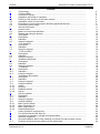
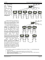
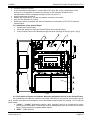
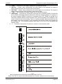
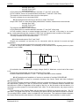
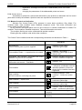
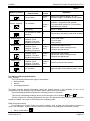
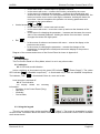
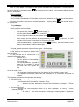
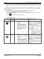
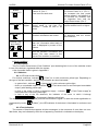
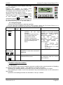
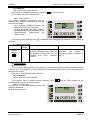
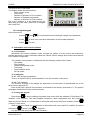
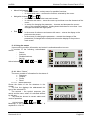
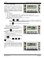
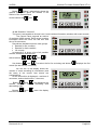
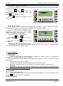
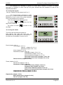
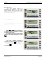
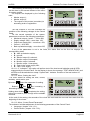
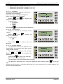
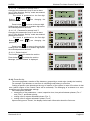
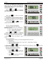
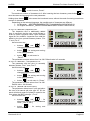
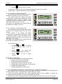
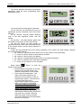
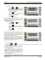
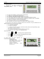
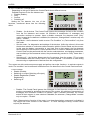
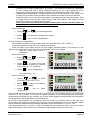
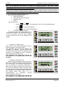
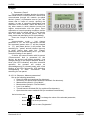
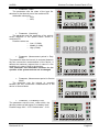
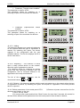
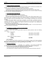
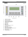
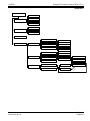
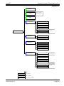
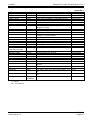
![[ENG] CE16-2 Manuale v2-8](http://vs1.manualzilla.com/store/data/005660444_1-7046d8e9760149eb635bc594076a0e4d-150x150.png)