1
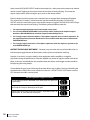
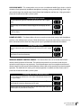
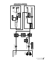
reference headphone amplifier owner’s manual Manual Rev G / Firmware v1.5 all contents © Grace Design/ Lunatec LLC Welcome Thanks for purchasing the Grace Design m902 reference headphone amplifier. We build all our products to be completely reliable and easy to use, so you can concentrate on producing great sounding audio, not struggling with complicated equipment or difficult to use product manuals. While the m902 has been designed to be straightforward to use, we do suggest that you spend a little time familiarizing yourself with the features and operational functions that are contained in this manual. Doing this now will make your experience with the m902 more enjoyable. In the event that you encounter any technical or operational difficulties with this or any Grace Design product, please feel free to contact us at 303-443-7454. Our office hours are from 9 to 5, Monday through Friday, MST. Or you can e-mail your questions to: [email protected] Also, please remember to visit our website www.gracedesign.com for the latest Grace Design product information, owner’s manuals and technical documents. Grace Design has been building audiophile quality products for the recording industry for over a decade. The technology developed for the m902, and all of our products, has evolved through a process of extensive listening, field testing and careful refinement. Your new m902 amplifier represents a combination of absolutely pristine audio performance, robust mechanical construction and bombproof reliability. Regardless of what type of work you do, your m902 will faithfully serve as an invisible link between your source audio and your headphones or speaker systems. We sincerely hope our products help you achieve a new level of excellence in your work! -The Grace Design Team. Table of Contents Important Safety Information m902 Key Features m902 Frontpanel m902 rearpanel Unpacking and Installing your m902 Powering up the m902 Input Connections Output Connections Selecting an Input Source About s-Locktm About x-Feed Accessing and Using the Submenu Wireless Remote Control Operation m902 Block Diagram infrared Remote Commands Specifications Cleaning and Maintenance Warranty Information Manual revisions 2 grace design m902 owner’s manual 3 4 5 6 6 7 8 9 9 10 11 12 15 17 18 19 20 20 21 Important Safety Information General ••Indoor use only ••Ordinary Protection: This equipment should not be exposed to dripping or splashing. ••Avoid placing objects filled with liquids, such as vases or glasses, on this equipment. ••Class I Equipment (grounded type) ••Electrical rating: 100-120/220-240V~ 50-60Hz 25W ••Mains supply voltage fluctuations are not to exceed ±10% of the nominal supply voltage. ••Pollution Degree 2 ••Installation (Overvoltage) Category II for transient overvoltages. ••Maximum Relative Humidity: <80% ••Operation temperature range: 10 °C to 40 °C ••Storage and transportation temperature range –40 °C to 70 °C ••Maximum altitude: 3000m (9843 ft) ••Equipment suitable for continuous operation ••Weight: 2.3kg (5lbs) Safety Marking Symbols CAUTION: READ ACCOMPANYING DOCUMENTS. This symbol, located on the equipment and in this manual, refers to important instructions. Read this manual thoroughly before operating this equipment. This symbol, located on the equipment and in this manual, indicates the potential for electrical shock hazard. Service Information The Grace Design m902 contains no user serviceable components. Contact Grace Design for repair and upgrade information. In the event that your Grace Design m902 needs to be returned to the factory, contact us for a return authorization number. grace design m902 owner’s manual 3 m902 Key Features ••Stereo analog inputs - balanced (+4dbu) XLR and unbalanced (-10dbv) RCA. ••Ultra low distortion 24-bit /192khz DAC accepts stereo digital input sources in AES3, S/PDIF and TOSLINK (optical) formats with auto sample rate detection and digital de-emphasis filter. ••USB input provides a convenient way for users to enjoy a reference quality monitoring experience when connected to their computer. This interface supports 16-bit audio at 44.1 Or 48kHz sample rates. ••s-locktm dual stage PLL (phase lock loop) circuitry for the ultimate in low jitter digital signal stability and sonic integrity. ••Unbalanced line level outputs (m902) are provided via rca jacks on the rear panel for connection to stereo monitors. ••Balanced line level outputs (m902b) are provided via ¼” tip-ring-sleeve (TRS) jacks on the rear panel for connection to stereo monitors. ••Front panel rotary encoder provides precision level control of both headphone and line output levels. Level adjustments are made in 0.5db steps within a 95db range. ••0.05db channel level matching to ensure true stereo balance at any monitoring level. ••A large, blue 7-segment display is used to show headphone and stereo main output levels. ••Calibration mode enables left/right balance adjustment for both headphone and mains outputs. There’s also a display dim mode that turns off all led’s except for the main power switch led. ••X-feed (crossfeed) simulates the acoustics of a loudspeaker listening environment which can significantly improve imaging while reducing listening fatigue when using headphones. This feature employs carefully designed signal cross-feed, filtering and delay circuits to simulate hrtf (head related transfer functions). ••High current transimpedance output amplifier design drives 8 ohm loads. The m902 was specifically designed with low impedance headphones in mind. ••Only the highest quality 0.5% metal film resistors are used throughout and there are no electrolytic capacitors in the signal path. Sealed gold contact relays are used for all signal switching. ••Infrared remote control for level control, left/right balance, mute and more when using the optional remote control unit. ••5 Year limited warranty on parts and labor. 4 grace design m902 owner’s manual m902 Frontpanel G F reference headphone amplifier AES S/PDIF UNBAL TOS BAL USB s-Lock 96 192 88 48 line K J push I H 176 44 phones OUTPUTS VOLUME A B xfeed INPUT E FS D C A ILLUMINATED POWER SWITCH - illuminates green when unit is powered on. B S-LOCK INDICATOR LED - illuminates when s-lock is active. C SAMPLE RATE INDICATOR LEDS - auto sample rate detection from selected digital input source. D ROTARY INPUT SELECTOR SWITCH - selects between all available inputs. E CROSSFEED INDICATOR LED - crossfeed circuitry is user activated in submenu. F OUTPUT LEVEL/EDIT ROTARY ENCODER - This stepped rotary encoder controls the selected output level in .5dB increments. This encoder is also used to adjust other settings found in the submenu. G OUTPUT LEVEL/SUBMENU DISPLAY - This blue, 2 digit display shows the current relative output level values based on the position of the main level rotary encoder. The range of this display is 0 to 99. Note the decimal represents a 0.5dB increment. This display is also used to give the user information in the submenu. H OUTPUT SELECTION LEDS – These LEDS indicate which output is currently selected by the user and under interface control. I INFRARED REMOTE RECEIVER – Receiver used for optional wireless remote control. J HEADPHONE OUTPUTS – Two stereo headphone output jacks wired in parallel. K FEET - four custom machined removable metal feet with neoprene inserts. grace design m902 owner’s manual 5 m902 rearpanel I H G E E C PUSH 120Vac S/PDIF PUSH L LINE OUT 1 2 A B UNBAL IN TOSLINK R AES3 1 2 3 R USB 1 2 3 PUSH 3 L BAL IN m902 D PUSH 120Vac S/PDIF 1 2 LINE OUT UNBAL IN 3 TOSLINK PUSH 1 2 AES3 R 1 2 3 R USB PUSH L 3 BAL IN L m902B (with balanced line outputs) A BALANCED ANALOG INPUT F TOSLINK DIGITAL INPUT B UNBALANCED ANALOG INPUT G S/PDIF DIGITAL INPUT C UNBALANCED LINE OUTPUT H USB DIGITAL INPUT D BALANCED LINE OUTPUT I E AC IEC INPUT MODULE AES DIGITAL INPUT Unpacking and Installing your m902 The m902 is shipped in one box which contains: the m902 unit, an AC power cord, a small plastic bag containing four hand-threaded machined metal feet, a warranty registration card and some additional Grace Design literature. OPEN AND INSPECT THE BOX Open all shipping boxes, carefully remove the m902 and put it aside. Before you go any further, check to make sure the above listed components are included with your shipment. If you believe something is missing, contact your friendly Grace Design dealer and they will make sure you’re taken care of. SAVE YOUR BOX!! We strongly encourage you to save the box and shipping materials supplied with your m902. They are specially designed to properly protect these valuable components, and in the unlikely event that you 6 grace design m902 owner’s manual need to return them for service, only these OEM shipping materials can ensure their safe return to our factory. REGISTER YOUR UNIT! Also, we strongly urge you to register your unit with Grace Design. We provide a limited 5 year warranty on all of our products, but if you don’t register your system, it’s hard for us to help you if and when help becomes necessary. So please take a few minutes to complete the enclosed warranty registration card and mail it in, or you can simply go to the warranty registration form on our web site. Thank you! INSTALLING THE FEET AND/ OR RACKMOUNTING The m902 is designed to either be placed on a stable surface in your studio or listening environment, or be rackmounted. If you don’t plan to rackmount your m902, first install the 4 supplied metal/rubber feet. Simply thread (hand tighten only) theses supplied feet by hand into the 4 vacant threaded holes in each corner of the underside of the m902. For rackmount installation, the m902 chassis has a #10-32 threaded insert mounting hole on the bottom towards the back. Two m902s can be mounted side by side in a standard 1U rack tray. Use a #10-32 x 1/2” or a #10-32 x 3/8” machine screw. Do not use a screw longer than 1/2”. Powering up the m902 Okay, let’s get started in making the necessary connections to get your m902 up and running. POWER CONNECTIONS The Disconnect Device for the m902 system is the Mains plug or the Appliance Coupler on the power supply cord. The Disconnect Device must remain accessible and operable. The power supply cord supplied with the m902 must be connected to a mains outlet with a protective earthing connection. CHECK LINE VOLTAGE SETTINGS The IEC power entry module has been set from the factory to operate at the voltage required for your part of the world. However, it’s important to double-check this in order to ensure no damage will come to the unit if power is applied and the setting is incorrect. LINE VOLTAGE SELECTOR To change the line voltage, remove the AC power chord from the power inlet then use a small screwdriver to pry open the voltage select door. Carefully remove the voltage select cam and re-insert it with the desired voltage showing. Use the table below for voltage settings and fuse values. Note that time delay or “slow blow” fuses are required. CAM SETTING 100V~ 120V~ 220V~ 240V~ 240V~ Voltage and Fuse information LINE VOLTAGE 100V~ 120V~ 220V~ 230V~ 240V~ FUSE VALUE 250V~ T 250mA L 250V~ T 250mA L 250V~ T 125mA L 250V~ T 125mA L 250V~ T 125mA L grace design m902 owner’s manual 7 AC POWER CORD Connect the supplied AC cord to the IEC power entry module on the rear panel of the m902. For safety, it is recommended that the cable be connected to a grounded outlet. POWER-UP SEQUENCE (VERY IMPORTANT!!) Before powering up your m902, if you are using the line level monitor outputs, make sure your monitor speakers or power amps connected to your monitors are turned OFF. This will prevent any “popping” in your speaker systems. Once the m902 and the rest of your audio system are powered up, turn on the power to your speakers (amplifiers). When powering down, we recommend that you first power off your speaker system and then power down the m902. It should also be noted that while the power sequence will not damage headphones connected to the m902, you should NOT be wearing them when power is applied or turned off because an audible and potentially loud ‘pop’ may occur. Input Connections The input/output/interface connections highlighted earlier in this manual are detailed below. Please contact us if you have any questions regarding cable terminations or pinout specifications. BALANCED ANALOG INPUTS - The balanced stereo analog input is provided via female XLRs. Connection is made using standard balanced XLR cables. This input is wired to the pin 1 shield, pin 2 positive pin 3 negative XLR standard. UNBALANCED ANALOG INPUT - This stereo input is provided for interfacing with consumer level (-10dBv) unbalanced analog sources. Connections are made using standard RCA cables. AES3 DIGITAL INPUT - The stereo AES3 input is provided via one female XLR connector. This conforms to the AES3 standard. Use of high quality 110 Ohm balanced cable is highly recommended. S/PDIF COAXIAL INPUT - Standard coaxial stereo digital input. The input impedance is 75 Ohms. Use a quality 75 Ohm cable for connections to this input. TOSLINK INPUT - Standard stereo optical input connector for use with consumer devices. Use a standard TOSLINK optical cable for connections to this input. USB INPUT - The stereo USB input for connection to a host PC or MAC. Use a standard USB TYPE A -to- TYPE B mini cable. The TYPE A connector is to be plugged in to the HOST PC and the TYPE B mini connector is to be used with the m902 input. 8 grace design m902 owner’s manual Output Connections STEREO HEADPHONE OUTPUTS - Headphone outputs are provided via two ¼” TRS (Tip, Ring, Sleeve) jacks. These outputs are wired in parallel. Connection to headphones should be made using standard ¼” TRS stereo connectors. UNBALANCED LINE OUTPUTS - (m902) A stereo pair of unbalanced line level outputs are provided via two RCA jacks. These outputs should be connected to powered speakers or power amplifiers using standard unbalanced RCA cables. BALANCED LINE OUTPUTS - (m902B) A stereo pair of balanced line level outputs are provided via two ¼” TRS jacks. These outputs should be connected to powered speakers or power amplifiers using standard balanced cables. Connection to an unbalanced input is also possible. See figure 1 and 2 for proper termination. Balanced Output 1/4” TRS Balanced Input XLR TIP RING pin 3 SLEEVE pin 2 pin 1 figure 1 balanced output to balanced input Unbalanced Input RCA Balanced Output 1/4” TRS TIP RING RING IS OPEN SLEEVE HOT GND SHIELD figure 2 balanced output to unbalanced input Once you’ve connected the power and have made all of the audio connections to your m902. Now the fun begins! The m902 has been designed to provide simple and intuitive operation. However, to get the most out of your m902, it is recommended that you read through the following sections carefully to learn the necessary details for operating your m902 reference headphone amplifier and monitor controller. Selecting an Input Source The m902 provides multiple analog and digital input sources. The rotary input selector switch is used to choose the input source for both the headphone amplifier and line output. ANALOG INPUTS - The m902 provides both balanced and unbalanced stereo inputs. To select either of these analog inputs, rotate the input selector to the desired input. When an analog input is selected, the m902’s internal reference DAC is shutdown. grace design m902 owner’s manual 9 DIGITAL INPUTS - The m902 provides the following digital input sources: AES3, S/PDIF, TOSLINK and USB. The AES3, S/PDIF and TOSLINK inputs support audio data with sample rates from 32kHz to 192kHz and resolution up to 24-bits. The USB input supports audio data with sample rates of 44.1kHz and 48kHz of 16-bit resolution. USB INPUT SETUP - To use the m902 USB input, the host computer must be properly configured. This procedure varies from computer to computer, but the general steps are as follows: 1. Once the m902 and host computer have been connected via USB, the host will automatically recognize the m902 as a USB Audio Device. 2. In your computer’s hardware setup, you must then select the m902 (USB Audio Device) as the playback hardware. 3. Once this is done, any audio being played on the host computer will be sent to the m902. It is recommended that all output volume controls be set to max on the host computer software. Depending on the application, failure to do so will result in a digitally attenuated signal, causing a loss in resolution. Operating Headphone And Line Outputs Both the headphone and the line outputs feature precision level control. Each output is completely independent of the other in terms of level and balance control (see the submenu section below for description of this feature). The output selection indicator LEDs show the user which output is currently under user control. To toggle the output control selection, simply press and release the rotary level encoder. You will see the selection indicator change. The rotary volume encoder is used to adjust the level of both the headphone and line level outputs independently. The level of the currently selected output is displayed in the 7-segment display. Turning the rotary encoder clockwise increases the output level and counter-clockwise decreases it. The m902 features an extremely high precision analog volume control. Step size is 0.5dB and channel matching is within 0.05dB for all settings. Also, embedded within the volume control architecture is a 3 stage acceleration curve. The rotary encoder has 24 positions. Turning it one revolution slowly will result in a change of 12dB (24 x 0.5dB). As the rotation speed increases, each step goes from 0.5dB to 2.0dB and then to 4.0dB. This allows not only precise control but also convenience when large volume changes are desired. Any changes made are reflected in the 7-segment display. Level range is from 0.0 to 99.5. NOTE: The least significant digit’s decimal point (.) is used to indicate 0.5dB increments About s-Locktm s-Locktm is our new PLL (Phase Lock Loop) circuitry that has been specifically developed for the m902 and its big brothers the m904 and multi-channel controller, the m906. The truly wonderful thing about s-Lock is that regardless of the condition of the external clock used as a reference for the m902, s-Lock 10 grace design m902 owner’s manual will take this clock source and provide an extremely stable and ultra-low jitter clock to run the DACs. The goal, of course, is pristine audio. We think you’re going to love s-Lock so here’s a bit more detail on how this works: s-Lock is a crystal-based PLL used for regenerating the incoming digital clock. The crystals used have extremely low intrinsic jitter and are capable of locking to sample rates of up to 192kHz. When the digital input selected for the DAC is active, the s-Lock circuitry automatically captures the incoming recovered clock from AES3, S/PDIF, TOSLINK, or USB. Once phase-lock with the incoming signal has been achieved, the DACs, which have been running off the original clock, are switched to run off the ultra-low jitter s-Lock system clock. If at any time s-Lock is lost or not achieved, the DACs are run off the original clock. The s-Lock system can effectively lock to input sample rates of 44.1kHz or 48kHz +/10Hz, 88.2kHz or 96kHz +/- 20Hz and 176.4kHz or 192kHz +/- 40Hz. If the incoming digital audio signal clock frequency is outside of these tolerances the s-Lock circuit will not lock and the s-Lock indicator on the m902 will extinguish. Even if the s-Lock does not achieve lock, the digital audio receiver circuits in the m902 can achieve excellent recovered clock jitter performance. About x-Feed When listening to loudspeakers in a room, your left ear hears sound primarily from the left speaker (and vice versa) but also receives a signal from the right speaker at a lower level and with some time delay compared to the right ear. As well, the right speaker sound that reaches the left ear does not have a flat frequency response as the sound waves have traveled around the shape of your head before reaching your left ear. The brain uses delay, level and frequency response characteristics to process the location of a sound and hence, create an aural image. When listening through headphones, each ear only hears the sound from one transducer and the mixing of signals between the ears does not exist. In this situation the brain is left without many of the psychoacoustic clues required to generate a properly distributed image and an accurate sound stage. The result is that instruments seem to cluster in the far left, far right or center of your head. Since the vital clues are absent, the brain has a difficult time deciding how to process the sounds coming from the headphone, which can result in listening fatigue when listening for extended periods of time. The m902 contains circuitry which electronically simulates the signal crossfeed that occurs in a real acoustic space and helps the brain establish instrument locations across the entire sound stage. While it is difficult to perfectly model the very complex level, delay and frequency response characteristics of the head, the cross feed circuitry in the m902 gives the brain some of the basic clues it needs and the result is a very pleasing simulation of an acoustic space. After extensive research and listening to many different crossfeed circuits, we chose to licence and implement an existing crossfeed circuit design called “The Natural Crossfeed Filter” which was designed by Jan Meier of Meier-Audio (www.meier-audio.de). grace design m902 owner’s manual 11 Accessing and Using the Submenu The m902 features a number of useful functions that can be accessed and adjusted using the submenu feature. To access the m902 submenu, simply press and hold the rotary encoder button. Once the m902 has entered the submenu, you will see the 7-segment display change to reflect the currently activated submenu mode. To navigate through the available submenu modes, simply press and release the rotary encoder button, which will scroll you through the available modes. Once the last mode is reached, pressing again will loop you back to the first mode. To exit the submenu at any time, press and hold the rotary encoder button. The 7-segment display will switch back to the current output level once the submenu has been exited. Note: When the submenu is exited, the last mode you were in will be the first mode activated the next time you enter the submenu. This allows quick access to the parameter you are currently adjusting. BALANCE MODE - The m902 offers individual Left-Right balance control for both the HEADPHONE and LINE outputs. Once in the m902 submenu, balance mode is indicated by the speaker symbol in the 7-segment display. Note: The m902 stores the balance level settings for both the headphone and line outputs in non-volatile memory and recalls these upon each power up. The front panel LED indicates the currently selected output. This is the output of which you have balance control over. To adjust the balance for the output not selected, you must first exit the submenu, select the other output and re-enter the submenu. activating balance mode Balance control of 6dB (in 0.5dB increments) is available for both outputs. When no balance offset has been made, both the left and right speaker symbols are shown in the 7-segment display. Turning the rotary encoder clockwise results in a balance adjust to the right. This will be indicated by the right facing speaker symbol changing to the corresponding balance offset value. Turning the rotary encoder counter-clockwise results in a balance adjust to the left. This will be indicated by the left facing speaker symbol changing to the corresponding balance offset value. If at any time you wish to restore the default (0) balance offset, simply return the balance control to center and this new setting will be saved. Balance settings are preserved whenever the m902 is power cycled. DISPLAY DIMMER MODE - The m902 features a highly readable user interface that gives the user all pertinent information. Situations may exist, however, when the user wishes to turn off this display. This is accomplished in the DISPLAY DIMMER mode. With the display dimmer turned off, the interface display functions without interruption. With the display dimmer enabled, the displays will extinguish after 4 seconds of inactivity. Any change made by the user or system change (sample rate or s-Lock 12 grace design m902 owner’s manual status) will turn the displays back on momentarily. Note: the dimmer feature mode is reset to OFF whenever the m902 is power cycled. activating the display dimmer Once you have entered the submenu, the DISPLAY DIMMER mode will be indicated by the double “d” symbol in the 7-segment display. Turning the rotary encoder clockwise turns the DISPLAY DIMMER mode ON. This is indicated with the decimal points illuminating in the double “d” symbol. Turning the rotary encoder counter-clockwise turns the DISPLAY DIMMER mode OFF. This is indicated by the double “d” symbol without the decimal points. CROSSFEED MODE (x-feed) - This feature is toggled on and off in the submenu, and its current status is preserved whenever the m902 is power cycled. activating crossfeed (x-feed) mode Once in the Submenu, the crossfeed mode is indicated by the “CF” symbol in the 7-segment display. Turning the rotary encoder clockwise turns the crossfeed mode ON. This is indicated with the decimal points illuminating in the “CF” symbol. Turning the rotary encoder counter-clockwise turns the crossfeed mode OFF. This is indicated by the “CF” symbol without the decimal points. EXCLUSIVE OUTPUT MODE - The m902 features a special mode that allows the user to toggle between outputs and mute the output not selected. The exclusive output mode can be very useful when referencing between the line outputs (controlling your speakers) and your headphones. Instead of having to manually mute or turn down the volume when toggling between outputs, the m902 handles this automatically. Once enabled, selecting the line output turns this output on (at the set volume) and mutes the headphone outputs. Selecting the headphone output turns this output on (at the set volume) and mutes the line outputs. Note: the EXCLUSIVE OUTPUT mode is reset anytime the m902 is powered down. activating exclusive output mode Once in the submenu, the EXCLUSIVE OUTPUT mode is indicated by the double “EO” symbol in the 7-segment display. Turning the rotary encoder clockwise turns the EXCLUSIVE OUTPUT mode ON. This is indicated with the decimal points illuminating in the double “EO” symbol. Turning the rotary encoder counter-clockwise turns the EXCLUSIVE OUTPUT mode OFF. This is indicated by the double “EO” symbol with out the decimal points. grace design m902 owner’s manual 13 Note: Once the EXCLUSIVE OUTPUT mode has been exited, as a safety measure the output not selected remains muted. Toggling to this output reveals the current level setting flashing. To unmute the output simply make a volume change or press mute on the remote control. Exclusive output mode has priority over a manual mute (as engaged from the optional IR remote). This means that if an output is muted manually with the remote and the m902 is in EXCLUSIVE OUTPUT mode, the mute setting stays active until the output is toggled. The EXCLUSIVE OUTPUT logic then overrides that manual mute setting. The following example demonstrates this: 1. Line output currently being monitored and is muted using the remote control. 2. The user enables EXCLUSIVE OUTPUT MODE (or it was previously enabled): At this point, the headphone output is muted due to EXCLUSIVE OUTPUT mode and the line output is muted manually by the user. 3. The user toggles output selection to headphones: The headphone output turns on due to exclusive output mode. The line output remains muted, but now the manual mute has been overridden and the mute status is a function of the EXCLUSIVE OUTPUT mode. 4. The user toggles output selection to line: The headphone output mutes and the line output once again turns on due to the EXCLUSIVE OUTPUT logic. OUTPUT TOGGLE LOCK OUT MODE - Situations may exist when the user of the m902 wishes to lock the output toggle function of the encoder switch to prevent inadvertent switching. Example: A musician is using the m902 in a live application and the amplifier is onstage for adjustment during the performance. Often the amplifier may be out of sight, but within reach of the talent. If musician accidentally hits the encoder button, the output would toggle and they would be left adjusting the wrong output. Once enabled, the pressing and releasing the encoder button has no affect. Pressing and holding the encoder button will allow the user to re-enter the submenu. OUTPUT TOGGLE LOCK mode is reset to OFF whenever the m902 is power cycled. activating output toggle lock mode Once in the submenu, the OUTPUT TOGGLE LOCK mode is indicated by the “OL” symbol in the 7-segment display. Turning the rotary encoder clockwise turns the OUTPUT TOGGLE LOCK mode ON. This is indicated with the decimal points illuminating in the “OL” symbol. Turning the rotary encoder counter-clockwise turns the OUTPUT TOGGLE LOCK mode OFF. This is indicated by the “OL” symbol without the decimal points. 14 grace design m902 owner’s manual HIGH GAIN MODE - This mode enables users to access an additional 10dB of gain, which is useful in situations where particularly innefficient headphones are being used at particularly high levels. High gain mode changes the overall output levels of both the headphone and line outs. High gain mode is preserved whenever the m902 is power cycled. selecting high gain mode Once in the submenu, the gain mode is indicated by the characters “LO” in the 7-segment display. Turning the rotary encoder clockwise activates the high gain mode and displays “HI” in the display Turning the rotary encoder counter-clockwise turns the high gain mode off. This is indicated by “LO” in the display. POWER UP LEVEL - This feature allows the user to save the current level settings, both headphone and line, as the defualt power up levels. While default levels are set to 0 at the factory, some users my find it convenient to have their unit always power up at a specified level other than the default. saving power up level Once in the submenu, the power up level is indicated by the characters “PL” in the 7-segment display. Turning the rotary encoder clockwise stores the current level as the power up level, which is indicated by the decimal points illuminating. INFRARED REMOTE CONTROL ENABLE - This feature allows the user to disable the infrared remote control operation of the m902. The m902 remote control uses command codes that are quite obscure, but they are not proprietary. Should interference occur from another manufacturer’s remote control unit, the remote control operation of the m902 can be turned off to prevent improper operation. The default for this setting is on (remote operation is enabled) and the current status is preserved whenever the m902 is power cycled. enabling the infrared remote control Once in the submenu, the infrared remote control enable is indicated by the characters “IR” in the 7-segment display. Turning the rotary encoder clockwise enables the m902 infrared remote control. This is indicated with the decimal points illuminating in the “IR” symbol. Turning the rotary encoder counter-clockwise disables the m902 infrared remote control. This is indicated by the “IR” symbol without decimal points. grace design m902 owner’s manual 15 Wireless Remote Control Operation An very high quality wireless remote control is available as an option for the m902. This remote control was custom designed for the m902 and provides very useful access to all of its features. The following section details all of the features available from the remote control. MUTE - Pressing and releasing this button toggles the mute setting for the currently selected output on the m902. Once pressed, this change will be reflected on the m902. Once an output is muted, the m902 continues displaying the current output level setting and will begin to flash. To disable muting simply press the mute button again. The output will return to the current level setting and the display will once again glow solid. In addition to pressing the mute button, mute can be turned off by making any volume change (on remote control or on the m902 itself ). Pressing and holding this button during any operation will toggle the exclusive output setting and will exit you from the submenu mode. The current exclusive output status will be displayed momentarily on the m902 display. MUTE X-FEED PHONES/ LINE BALANCE VOL VOL X-FEED - Pressing this button toggles the x-feed status on the m902. The current x-feed status will be displayed momentarily on the m902 display. Pressing will also exit the submenu mode and return the user to normal operation. PHONES/LINE - Pressing and releasing this button during normal operation toggles the selected output under control. Once pressed, this change will be reflected on the m902 display. The newly selected output indicator m902 infrared will illuminate and the corresponding level will be displayed. Pressing and remote unit releasing this button while in balance mode will toggle the selected output under balance adjust. The newly selected output indicator will illuminate and the corresponding balance level will be displayed. Pressing and holding this button during any operation will enable toggle the display dimmer setting and will exit you from the submenu mode. The current display dimmer status will be displayed momentarily on the m902 display. BALANCE - Pressing this button during normal operation (or when in any other submenu mode) will enter balance mode within the submenu. Pressing this button while the m902 is in balance mode will exit the user from the submenu and balance mode. Once in balance mode, offsets can be adjusted using the volume up/ volume down buttons as detailed below. VOLUME UP / VOLUME DOWN - In normal operation pressing the volume up or down buttons will change the selected m902 output level respectively. NOTE: The longer the button is held the quicker the volume level changes.Pressing the volume up or down buttons while in balance mode will adjust the left (vol down) and right (vol up) balance. In normal operation, pressing the volume up or down buttons while the selected output is muted will unmute the output. 16 grace design m902 owner’s manual m902 Block Diagram ANALOG INPUTS UNBALANCED ANALOG INPUT BALANCED ANALOG INPUT DIGITAL INPUTS AES INPUT TOSLINK INPUT S/PDIF INPUT USB INPUT UNBALANCED INPUT AMP INPUT SELECT AUDIO BALANCED INPUT AMP INPUT SELECT AES3 RX s-Lock PLL CLOCK INPUT SELECT DAC 192kHZ / 24 BIT HEADPHONE OUTPUT 2-CHANNEL LEVEL CONTROL LEVEL BALANCE MUTE 2-CHANNEL LINE OUTPUT LEVEL CONTROL CROSSFEED CROSSFEED ENABLE TRANSIMPEDANCE HEADPHONE AMPLIFIER LINE OUTPUT AMPLIFIER OUTPUTS OUTPUTS HEADPHONE UNBALANCED ANALOG OUTPUT 17 grace design m902 owner’s manual infrared Remote Commands The m902 infrared remote control uses a 32-bit command set. It operates at 38kHz. In addition to the single press commands, several m902 RCU commands make use of the press hold feature. The following table lists the implemented command set. 18 RCU Action Description Command Repeated HOLD Command MUTE Press & Release Toggles MUTE state of selected output 0x02FDD827 - MUTE Press & Hold Toggles EXCLUSIVE OUTPUT mode setting 0x02FDD827 0x000000BB CROSSFEED Press & Release Toggles CROSSFEED mode setting 0x02FD08F7 - PHONES / LINE Press & Release Toggles selected m902 OUTPUT 0x02FD58A7 - PHONES / LINE Press & Hold Toggles DISPLAY DIM mode setting 0x02FD58A7 0x000000BB BALANCE Press & Release Toggles in and out of BALANCE adjust mode 0x02FD7887 - VOLUME UP Press & Release Increments VOLUME or BALANCE UP 0x02FDE01F - VOLUME UP Press & HOLD Continuously increments VOLUME 0x02FDE01F or BALANCE UP 0x000000BB VOLUME DOWN Press & Release Increments VOLUME or BALANCE DOWN - VOLUME DOWN Press & HOLD Continuously increments VOLUME 0x02FD906F or BALANCE DOWN grace design m902 owner’s manual 0x02FD906F 0x000000BB Specifications GAIN Normal Mode Boost Mode +0dB +10dB FREQUENCY RESPONSE @ 0dBu out +/- .25dB 22Hz - 120kHz @ 0dBu out +/- .5dB 12Hz - 260kHz @ 0dBu out +/-3dB 4Hz - 600kHz MAXIMUM OUTPUT LEVEL @1kHz, 50 Ohm load +21.4dBu (9.11Vrms) IMPEDANCE INPUT 53K Ohms balanced INPUT 53K Ohms unbalanced OUTPUT 1 Ohm DYNAMIC RANGE @ 0dB gain 116dB @ -10dB gain 119dB THD+N +10dBu out, 50 Ohm load, SMPTE 4:1 <0.01% Headphone +10dBu out, 50 Ohm load <0.008% Line Out +10dBu out <0.02% ATTENUATOR CHANNEL MATCHING Attenuator switch <0.05dB Attenuator range 99.5dB D/A SPECIFICATIONS Input sample rate 32, 44.1, 48, 88.2, 96, 176.4, 192kHz THD+N 44.1kHz, 24-bit, 1kHz, +20dBu out <0.002% NOISE FLOOR 0dB gain, 22-22kHz -94dBu 0dB gain, A-weighted -97dBu POWER REQUIREMENTS 115VAC .16A 230VAC .08A grace design m902 owner’s manual 19 Cleaning and Maintenance Your m902 amplifier chassis is constructed out of high quality stainless steel. Under normal circumstances, virtually no maintenance is required to keep the unit looking shiny and new. However, if your unit becomes smudged or dirty, here are some cleaning tips: We recommend using either Pledge furniture polish or Zep brand stainless steel cleaner (available at the hardware store). Apply cleaner to a clean, dry, lint free cloth and gently wipe all stainless surfaces, taking care not to allow the cleaning product to build up around the panel switches or knobs. Warranty Information 1. Grace Design warrants all of our products to be free of defective parts and workmanship for a period of five years. This warranty period begins at the original date of purchase and is transferable to any person who may subsequently purchase the product during this time. 2. This warranty excludes the following conditions: normal wear and tear, misuse, customer negligence, accidental damage, unauthorized repair or modification, cosmetic damage and damage incurred during shipment. 3. During the time of this warranty, Grace Design will repair or replace, at its option, any defective parts or repair defective workmanship without charge, provided the customer has appropriate proof of purchase and that the product has its original factory serial number. 4. In order for Grace Design to provide efficient and timely warranty service, it is important that you mail the completed warranty registration card enclosed with all of our products within 10 days of the original date of purchase. You may also register your product directly with Grace Design by telephone (303-443-7454 Monday-Friday 9:00am to 5:00pm MST), or you can register your product online at www. gracedesign.com. 5. This warranty is in lieu of all other warranties whether written, expressed, or implied, INCLUDING ANY WARRANTIES OF MERCHANTABILITY OR FITNESS FOR A PARTICULAR PURPOSE. 6. In no event will Grace Design be liable for lost profits or any other incidental, consequential or Exemplary damages, even if Grace Design is aware of the possibility of such damages. In no event will Grace Design’s liability exceed the purchase price of the product 7. This warranty gives the customer specific legal rights. The customer may also have other rights, which vary from state to state. Some states do not allow limitations on implied warranties or consequential damages, so some of the limitations of the above may not apply to a particular customer. 20 grace design m902 owner’s manual manual revisions Revision Page A-B Change Date Initials Initial release E all added TRS to XLR diagram, revised layout 4/07/08 edg F all firmware update to Rev 1.5 8/26/08 edg G 8 Added IF remote commands, Changed wording in power up sequence. 7/22/09 edg grace design m902 owner’s manual 21