1
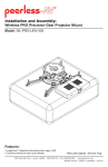
Installation and Assembly Manual:
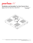
PRG Precision Gear Projector Mount
Models: PRG-1, PRG-1S, PRG-1W
Max UL Load Capacity: 50 lb (22.68 kg)
Features:
• ImageLockTM alignment prevents picture sag or drift
• Exclusive aluminum track quick release
2300 White Oak Circle • Aurora, Il 60502 • (800) 865-2112 • Fax: (800) 359-6500 • www.peerlessmounts.com
ISSUED: 08-15-07 SHEET #: 055-9491-8 07-15-11
NOTE: Read entire instruction sheet before you start installation and assembly.
WARNING
• Do not begin to install your Peerless product until you have read and understood the instructions and warnings
contained in this Installation Sheet. If you have any questions regarding any of the instructions or warnings, please
call Peerless customer care at 1-800-865-2112.
• This product should only be installed by someone of good mechanical aptitude, has experience with basic building
construction, and fully understands these instructions.
• Make sure that the supporting surface will safely support the combined load of the equipment and all attached
hardware and components.
• Never exceed the Maximum UL Load Capacity. See page 1.
• If mounting to wood joist ceilings, make sure that mounting screws are anchored into the center of the joist. Use of
an "edge to edge" stud finder is highly recommended.
• Always use an assistant or mechanical lifting equipment to safely lift and position equipment.
• Tighten screws firmly, but do not overtighten. Overtightening can damage the items, greatly reducing their holding
power.
• This product is intended for indoor use only. Use of this product outdoors could lead to product failure and personal
injury.
• This product was designed and intended to be mounted to the following supporting surfaces checked below with
the hardware included in this product as specified in the installation sheet. To mount this product to an alternative
supporting surface, contact Peerless customer care at 1-800-865-2112.
• This product was designed to be installed on the following ceiling construction only;
CEILING CONSTRUCTION
ADDITIONAL HARDWARE REQUIRED
x
x
x
None
None
None
Contact Customer Service (Not Evaluated by UL)
Contact Customer Service (Not Evaluated by UL)
Wood Stud
Wood Joist
Solid Concrete
Brick
Other or unsure?
• 5/16" drill bit for concrete surface
Tools Needed for Assembly
• stud finder ("edge to edge" stud finder is recommended)
• phillips screwdriver
• drill
• 5/32" drill bit for wood joists
• open end wrench
• level
Table of Contents
Parts List................................................................................................................................................................................. 3
Installation to Extension Columns / Ceiling Plate ...................................................................................................................4
Installation to Wood Joist Ceilings ..........................................................................................................................................5
Installation to Concrete Ceilings .............................................................................................................................................6
Installation to Threaded Rods................................................................................................................................................. 7
Attaching Adapter Plate to Projector.......................................................................................................................................8
Attaching Adapter Plate to Projector Mount............................................................................................................................9
Cable Management ..............................................................................................................................................................10
Projector Alignment .............................................................................................................................................................. 11
Accessories ....................................................................................................................................................................12, 13
2 of 13
Visit the Peerless Web Site at www.peerlessmounts.com
ISSUED: 08-15-07 SHEET #: 055-9491-8 07-15-11
For customer care call 1-800-865-2112
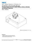
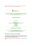
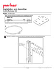
Before you start check the parts list to insure all of the parts shown are included.
Parts List
Description
A projector mount assembly
B 4 mm security allen wrench
C #10-32 x 3/8" serrated washer head socket pin screw
D #10-32 x 1/4" socket pin screw
E flat washer
F #14 x 2-1/2 phillips hex head wood screw
G concrete anchor
H 2 mm security allen wrench
I connection block
Qty.
1
1
2
1
2
2
2
1
1
PRG-1
Part #
054-1171
560-9646
520-1151
520-1196
540-1078
5S1-015-C03
590-0320
560-1097
580-1065
PRG-1S
Part #
054-4171
560-9646
520-2151
520-2196
540-1078
5S1-015-C04
590-0320
560-1097
580-4065
PRG-1W
Part #
054-2171
560-9646
520-2151
520-2196
540-1078
5S1-015-C04
590-0320
560-1097
580-4065
NOTE: Actual parts may appear slightly different than illustrated.
A
C
I
D
B
F
E
3 of 13
Visit the Peerless Web Site at www.peerlessmounts.com
G
H
ISSUED: 08-15-07 SHEET #: 055-9491-8 07-15-11
For customer care call 1-800-865-2112
Installation to Extension Column / Ceiling Plate
1
NOTE: Refer to accompanying instructions with ceiling plates (sold separately) for installing these models to
ceiling.
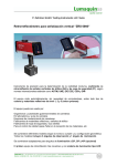
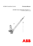
Screw projector mount assembly (A) onto extension column as shown in figure 1.1. Tighten swivel stop screw
against extension column, flush mount tube or reducer using 4mm security allen wrench (B) as shown in figure
1.2.
NOTE: Swivel stop screw is used to jam against threads of extension column, flush mount tube or reducer to
prevent any excess movement of projector mount assembly (A). Do not overtighten screw; overtightening screw
will damage threads making it difficult to separate products.
Skip to step 5.
1-1/2" EXTENSION COLUMN
(SOLD SEPARATELY)
(UL LISTED EXT OR AEC SERIES)
A
ARROW INDICATES
FRONT OF MOUNT
fig. 1.1
CMJ 455
(SOLD SEPARATELY)
SWIVEL STOP SCREW
fig. 1.2
4 of 13
Visit the Peerless Web Site at www.peerlessmounts.com
ISSUED: 08-15-07 SHEET #: 055-9491-8 07-15-11
For customer care call 1-800-865-2112
Installation To Wood Joist Ceilings
WARNING
• Installer must verify that the supporting surface will safely support the combined load of the equipment and all
attached hardware and components.
• Tighten wood screws so that projector mount assembly is firmly attached, but do not overtighten. Overtightening
can damage the screws, greatly reducing their holding power.
• Never tighten in excess of 80 in. • lb (9 N.M.).
• Make sure that mounting screws are anchored into the center of the stud. The use of an "edge to edge" stud finder
is highly recommended.
• Hardware provided is for attachment of mount through standard thickness drywall or plaster into wood studs.
Installers are responsible to provide hardware for other types of mounting situations (Not Evaluated by UL).
2
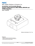
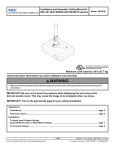
Place projector mount assembly (A) on ceiling as a template and mark the center of the two mounting holes.
Make sure that the mounting holes are in the center of the wood joist. Drill two 5/32" (4mm) dia. holes to a
minimum depth of 2-1/2" (64mm). Attach projector mount assembly (A) with two #14 x 2-1/2" (6mm x 65mm)
wood screws (F) and two flat washers (E) as shown in figure 2.1 or figure 2.2 depending on joist orientation.
NOTE: Mounting slots on projector mount assembly allow for 30° (±15°) of swivel adjustment before fully securing
wood screws.
Tighten wood screws (F) using 3/8" (10mm) socket wrench, phillips screwdriver or 10mm open end wrench until
projector mount assembly (A) is firmly attached.
Skip to step 5.
WOOD JOIST
ACCESS SLOT FOR
OPEN END WRENCH
ALLOWS TIGHTENING
OF WOOD SCREW
WOOD JOIST
FRONT OF
MOUNT
A
A
ARROW ON TOP OF
PROJECTOR MOUNT
ASSEMBLY INDICATES
FRONT OF MOUNT
E
E
F
F
fig. 2.2
fig. 2.1
5 of 13
Visit the Peerless Web Site at www.peerlessmounts.com
ISSUED: 08-15-07 SHEET #: 055-9491-8 07-15-11
For customer care call 1-800-865-2112
Installation to Concrete Ceilings
WARNING
• Concrete must be 2000 psi density minimum. Lighter density concrete may not hold concrete anchor.
• Make sure that the supporting surface will safely support the combined load of the equipment and all attached
hardware and components.
3
Place projector mount assembly (A) on ceiling
as a template and mark the center of the two
mounting holes. Drill two 5/16" (8mm) dia. holes
to a minimum depth of 2-1/2" (64mm). Attach
projector mount assembly (A) using two concrete
anchors (G), two flat washers (E), and two
#14 x 2-1/2" wood screws (F) as shown in
Illustration A and 1, 2 and 3).
1
concrete
surface
G
Drill holes and insert anchors (G).
NOTE: Mounting slots on projector mount
assembly allow for 30° (±15°) of swivel adjustment
before fully securing wood screws.
Tighten wood screws (F) using 3/8" (10mm) socket
or open end wrench or phillips screwdriver until
projector mount assembly (A) is firmly attached.
2
A
G
F
Place plate (A) over anchors (G) and secure with screws (F).
3
WARNING
• Tighten wood screws firmly, but do not overtighten.
Overtightening can damage the screws, greatly
reducing their holding power.
Tighten all fasteners.
• Never tighten in excess of 80 in • lb (9 N.M.).
WARNING
CONCRETE CEILING
• Always attach concrete anchors directly to loadbearing concrete.
CUTAWAY VIEW
• Never attach concrete anchors to concrete covered
with plaster, drywall, or other finishing material.
If mounting to concrete surfaces covered with a
finishing surface is unavoidable (not evaluated by
UL), the finishing surface must be counterbored
as shown below. Be sure concrete anchors do not
pull away from concrete when tightening screws. If
plaster/drywall is thicker than 5/8", custom fasteners
must be supplied by installer (not evaluated by UL).
INCORRECT
concrete
A
plaster/
dry wall
G
CORRECT
A
concrete
plaster/
dry wall
ARROW ON TOP
OF PROJECTOR
MOUNT ASSEMBLY
INDICATES FRONT
OF MOUNT
A
E
F
Illustration A
6 of 13
Visit the Peerless Web Site at www.peerlessmounts.com
ISSUED: 08-15-07 SHEET #: 055-9491-8 07-15-11
For customer care call 1-800-865-2112
Installation to Threaded Rod
(Not evaluated by UL - Professional installation only)
4
Thread two 1/4-20 hex thin nylon-insert locknuts (not included) on two 1/4-20 threaded rods (not included) to the
desired height of projector mount assembly. Attach projector mount assembly (A) to the two 1/4-20 threaded rods
using two 1/4-20 hex thin nylon-insert locknuts as shown in figure 4.1 or figure 4.2.
1/4-20 THREADED ROD
(NOT INCLUDED)
1/4-20 THREADED ROD
(NOT INCLUDED)
1/4-20 HEX THIN
NYLON-INSERT
LOCKNUT
(NOT INCLUDED)
1/4-20 HEX THIN
NYLON-INSERT
LOCKNUT
(NOT INCLUDED)
A
A
ARROW
INDICATES
FRONT OF
MOUNT
ARROW
INDICATES
FRONT OF
MOUNT
fig. 4.1
1/4-20 HEX THIN
NYLON-INSERT
LOCKNUT
(NOT INCLUDED)
1/4-20 HEX THIN
NYLON-INSERT
LOCKNUT
(NOT INCLUDED)
7 of 13
Visit the Peerless Web Site at www.peerlessmounts.com
fig. 4.2
ISSUED: 08-15-07 SHEET #: 055-9491-8 07-15-11
For customer care call 1-800-865-2112
Attaching Adapter Plate to Projector
CAUTION
I
fig. 5.1
• It is the responsibility of the installer to ensure that
the projector is properly ventilated.
5
SHOULDER
NOTCH INDICATES
FRONT OF
PROJECTOR
Installing Dedicated PAP Series
Adapter Plate (sold separately)
DEDICATED
ADAPTER PLATE
(SOLD SEPARATELY)
NOTE: The projector dedicated adapter plate you
are installing may differ in appearance from the
sample illustrated in figure 5.1.
Align shoulder of connection block (I) opposite
notch of adapter plate. Attach dedicated adapter
plate to connection block (I) using two #10-32 x
3/8" serrated washer head socket pin screws (C)
as shown in figure 5.1.
NOTE: For PAP 35, PAP 40, and PAP 45 adapter
plates, use two #10-32 x 3/4" screws provided with
adapter plate in place of screws (C).
C
NOTE: Attach dedicated adapter plate to projector
(see PAP instructions) before proceeding to
step 6.
I
5
Installing PAP-UNV Adapter Plate (sold
separately)
Align shoulder on connection block (I) opposite
notch in adapter plate. Attach PAP-UNV adapter
plate to connection block (I) using two #10-32 x
3/8" serrated washer head socket pin screws (C)
as shown in figure 5.2.
fig. 5.2
SHOULDER
NOTCH INDICATES
FRONT OF
PROJECTOR
NOTE: Attach PAP-UNV adapter plate to projector
(see PAP-UNV instructions) before proceeding to
step 6.
PAP-UNV
ADAPTER PLATE
(SOLD SEPARATELY)
C
8 of 13
Visit the Peerless Web Site at www.peerlessmounts.com
ISSUED: 08-15-07 SHEET #: 055-9491-8 07-15-11
For customer care call 1-800-865-2112
Attaching Adapter Plate to Projector Mount
WARNING
• Do not lift more weight than you can handle. Use additional man power or mechanical lifting equipment to safely
handle placement of the projector.
6
Slide connection block (I) with projector into projector mount assembly (A) as shown. Tighten captive screw to
secure projector to projector mount assembly (A).
FRONT OF MOUNT
ARROW INDICATES
FRONT OF MOUNT
A
I
CAPTIVE SCREW
7
IMPORTANT: For security installations, insert one #10-32 x 1/4" socket pin screw (D) through projector mount
assembly (A) and into connection block (I) as shown. Tighten screw using 4mm security allen wrench (B).
A
I
D
9 of 13
Visit the Peerless Web Site at www.peerlessmounts.com
ISSUED: 08-15-07 SHEET #: 055-9491-8 07-15-11
For customer care call 1-800-865-2112
Cable Management
8
fig. 8.1
To make an opening to route cables through
projector mount assembly, adjust projector mount
assembly to full upward tilt position by turning
knob for tilt adjustment as shown in figure 8.2.
Left or right roll position can be adjusted if more
space is required.
CABLES WITH COMBINATION
OF VGA CONNECTOR
AND RCA PLUGS
NOTE: Be certain tamper resistant screws are not
engaged before making adjustments (see step 9).
Route cables through top of extension column as
shown in figure 8.1 and figure 8.2.
NOTE: A method for assisting cables through
extension column may be required (example:
string tied to connector to help pull through
extension column).
BEND WIRES OF RCA
PLUGS IN OPPOSITE
DIRECTION
CABLE
CONNECTOR
ROUTE
CONNECTOR
THROUGH
FIRST
INNER
DIAMETER OF
EXTENSION
COLUMN
DO NOT
CRIMP
WIRES
Route cables through projector mount assembly
as shown in figure 8.2 and connect to projector.
NOTE: INNER DIAMETER OF
EXTENSION COLUMN MAY NOT
ALLOW PASSAGE FOR ALL
CONNECTOR TYPES.
fig. 8.2
EXTENSION COLUMN
KNOB FOR ROLL
ADJUSTMENT
OPENING
FOR ROUTING
CABLES
KNOB FOR TILT
ADJUSTMENT
10 of 13
Visit the Peerless Web Site at www.peerlessmounts.com
ISSUED: 08-15-07 SHEET #: 055-9491-8 07-15-11
For customer care call 1-800-865-2112
Projector Alignment
To adjust yaw (swivel) for threaded rod mounting applications: Loosen locknuts on threaded rods
(step 4), until projector mount can be rotated. Rotate mount to desired position and retighten locknuts.
9
To adjust yaw (swivel) for extension column applications: Loosen screw on projector mount assembly (A)
indicated below until projector mount can be rotated. Rotate mount to desired position and retighten screw.
To adjust pitch (forward and backward tilt): Turn knob on back of mount as shown below. Pull knob out and
turn by hand for easy adjustment or insert #2 phillips screwdriver in end of knob and turn.
To adjust roll (side to side tilt): Turn knob on side of mount as shown below. Pull knob out and turn by hand for
easy adjustment or insert #2 phillips screwdriver in end of knob and turn.
ARROW INDICATES
FRONT OF MOUNT
A
KNOB FOR PITCH
ADJUSTMENT
ACCESS SLOT FOR
OPEN END WRENCH
ALLOWS TIGHTENING
OF LOCKNUTS
WITHOUT REMOVING
PROJECTOR
BACK OF MOUNT
KNOB FOR ROLL
ADJUSTMENT
SCREW FOR YAW (SWIVEL) STOP
(REFER TO STEP 1, INSTALLATION
TO EXTENSION COLUMNS, FIG. 1.1)
9-1
To prevent tampering with the pitch and roll adjustments: Tighten the two tamper resistant security screws
on the projector mount assembly using 4mm security allen wrench (B) to lock the pitch and roll adjustments as
shown below.
NOTE: Tighten screws firmly, but do not overtighten. Overtightening can damage the mount.
CAUTION
• Do not adjust pitch or roll while tamper resistant security screws are fully engaged.
• Loosen the two tamper resistant security screws one complete turn before adjusting the projector mount assembly
or damage may occur.
TO LOCK ROLL,
TIGHTEN
TAMPER
RESISTANT
SECURITY SCREW
TO LOCK PITCH,
TIGHTEN
TAMPER RESISTANT
SECURITY SCREW
SIDE VIEW
FRONT VIEW
11 of 13
Visit the Peerless Web Site at www.peerlessmounts.com
ISSUED: 08-15-07 SHEET #: 055-9491-8 07-15-11
For customer care call 1-800-865-2112
PRG Series Projector Mount Accessories
Ceiling Plates
Escutcheon Ring
Unistrut® Adapter
Truss Ceiling Adapter
MODEL: ACC 557*
MAX LOAD: 250 lbs. (113.4 kg.)
COLOR: Black
MODEL: ACC 640
MODEL: ACC 550
MAX LOAD: 250 lbs. (113.4 kg.)
COLOR: Black
• Covers hole where extension
column passes through ceiling
• Hinged ring wraps around extension column
• Included with CMJ 500
R
• Attaches to a square, round,
rectangular, or I-Beam truss up to 3" in
diameter
New!
• Designed for use with
1 5/8" x 1 5/8" 12 gauge Unistrut
New!
Lightweight Cathedral
Ceiling Plate
Lightweight Adjustable
Suspended Ceiling Kit
R
MODEL:
ACC570(S)(W)
COLOR: Black, silver or white
MAX LOAD: 150 lb (68 kg)
SHIP WEIGHT: 1.7 lb (.8 kg)
MODEL: ACC 912*
MAX LOAD: 60 lbs. (27.2 kg.)
COLOR: Black
MODEL: CMJ 500
MAX LOAD: 60 lbs. (27.2 kg.)
COLOR: White
• Designed specifically for projectors
• Allows a projector to be mounted
on an angled ceiling
• Mounts above 2’ x 4’ or 2’ x 2’ false
ceiling tile
• Includes tie wire supports, flush mount
tube, and offers two knockout panels
for outlet boxes
• Offers unlimited adjustment for
projector placement
Lightweight Suspended Ceiling Kit
MODEL: CMJ 455
MAX LOAD: 50 lbs. (22.7 kg.)
COLOR: White
Unistrut
MODELS:
CMJ 300*, CMJ 310*
MAX LOAD:
• Five different projector
mount attachment points
• Includes tie wire supports,
flush mount tube, and
offers two knockout panels
for outlet boxes
• May either replace a 2’ x 2’ false
ceiling tile or mount above an existing
2’ x 2’ or 2’ x 4’ ceiling tile
R
I-Beam Clamps
MODELS:
ACC 558, ACC 559
MAX LOAD: 250 lbs. (113.4 kg.)
COLOR: Black
Unistrut or Structural
Ceiling Plates
250 lbs. (113.4 kg.)
COLOR: Black
Round Ceiling Plate
Ceiling plate
• CMJ 300 is a 4" x 4" ceiling plate
• CMJ 310 is a 8" x 8" ceiling plate
• Designed for a Unistrut ceiling
(1 5/8" x 1 5/8" 12 gauge Unistrut)
or a solid structural ceiling
(mounting hardware not included)
R
• Designed for finished or
structural ceilings (wood or
concrete)
• Features a cord management
Anti-Vibration Ceiling Plates
MODELS:
ACC 840*, ACC 845*
MAX LOAD: 60 lbs. (27.2 kg.)
COLOR: Black
• ACC 840 was designed for
a structural ceiling (wood only)
• ACC 845 was designed for
a Unistrut ceiling (1 5/8" x 1 5/8"
12 gauge Unistrut)
• Reduces unwanted vibrations
that may cause internal damage
to the equipment and/or cause the
screen image to vibrate
• Features two cord management
access holes
• Patent pending
Accessory Pack for CMJ 455
MODEL: ACC 455*
R
This pack includes 4 hanger brackets and
4 hanger clamps for additional stability. For
use with model CMJ 455.
• ACC 558 clamps onto 4"-8" I-Beam
• ACC 559 clamps onto 7"-12" I-Beam
* = Not UL Listed
12 of 13
Visit the Peerless Web Site at www.peerlessmounts.com
ISSUED: 08-15-07 SHEET #: 055-9491-8 07-15-11
For customer care call 1-800-865-2112
PRG Series Projector Mount Accessories
Cord Management
• Includes, four, 2' sections
• Designed to externally route cords along the
outside of an 1/2" extension column
• Sections can be stacked to create longer lengths
or cut to desired length
Cord Wrap
MODELS: ACC 852(W)(S)*
COLOR: Black, White, or Silver
Extension Columns
Fixed Length 1 1/2"
Extension Columns
Adjustable Length 1 1/2"
Extension Columns
COLOR: Black
COLOR: Black
MODEL
EXT 006
EXT 018
EXT 101
EXT 102
EXT 103
EXT 104
EXT 105
EXT 106
EXT 107
EXT 108
EXT 109
EXT 110
Drop Length
8" (20 cm)
20" (51 cm)
14" (36 cm)
26" (66 cm)
38" (97 cm)
50" (127cm)
62" (158 cm)
74" (188 cm)
86" (219 cm)
98" (249 cm)
110" (279 cm)
122" (310 cm)
Ship Weight
2.5 lbs (1.13 kg)
5 lbs (2.27 kg)
3.5 lbs (1.59 kg)
6 lbs (2.72 kg)
9.25 lbs (4.2 kg)
12 lbs (5.44 kg)
14.75 lbs (6.69 kg)
18 lbs (8.16 kg)
20.75 lbs (9.41 kg)
23.25 lbs (10.55 kg)
26.5 lbs (12.02 kg)
29 lbs (13.15 kg)
MODEL
ADJ 006009
ADJ 012018
ADJ 018024
ADJ 0203
ADJ 0305
ADJ 0406
ADJ 0507
ADJ 0608
ADJ 0709
ADJ 0810
ADJ 0911
ADJ 1012
R
Drop Length
8"-11"
14"-20"
20"-26"
26"-38"
38"-62"
50"-74"
62"-86"
74"-98"
86"-110"
98"-122"
110"-134"
122"-146"
Ship Weight
4 lbs. (1.81 kg)
4.75 lbs. (2.15 kg)
6.25 lbs. (2.83 kg)
8 lbs. (3.63 kg)
13.5 lbs. (6.12 kg)
16.25 lbs. (7.37 kg)
18.5 lbs. (8.39 kg)
21.75 lbs. (9.87 kg)
24.5 lbs. (11.11 kg)
27 lbs. (12.25 kg)
29 lbs. (13.15 kg)
31 lbs. (14.06 kg)
R
Security Accessories
Armor LockTM Plus Security Cables
MODEL: ACC 020*
MODEL: ACC 021*
• With security lock
• For use with projectors that have a built-in
security slot
• With 1/4" security cable and fasteners
• Includes adhesive for non-fastener applica
tions
ALLIGATOR
Concrete Anchors
Extension Column
Stabilizer Kit
MODEL: ACC 050*
COLOR: Black
MODELS: ACC 203, 204
• ACC 203 contains 3 anchors
• ACC 204 contains 4 anchors
• Used for attachment to
concrete, concrete block,
or brick
• Used in conjunction with wood
screws (supplied with
projector mount and/or
ceiling plate)
• Expands in length and binds to
the contours of the hole and
the screw
• Can be used to reduce
unwanted swaying that may
occur with extension
column installations
• Includes a hose clamp, two
stabilizer column supports,
& hardware for mounting to
wood joists
• For use with extension
columns over 21"
Side-To-Side Adjuster
R
Extension Column
Connector
MODEL: ACC 830*
COLOR: Black
• Provides 4" of radial
adjustment side to side
• Includes Flush Mount
Tube, EXT 002
Additional Projector
Mount Accessories
®
Extension
column
Side to side
adjuster
* = Not UL Listed
MODEL: ACC 109*
COLOR: Black
• Can be used to join two
1-1/2" extension columns to
create a maximum length
of 20’
• Secures to columns with
Armor LockTM Security
screws
13 of 13
Visit the Peerless Web Site at www.peerlessmounts.com
Extension Column Connector
with Cord Management
MODEL: ACC800, ACC850(S)
COLOR: ACC800 Black
ACC850 Black or Silver
• 1-1/2" access hole for internal cord
management
• Unit has 1-1/2"-11.5 NPT fitting for
attachment of extension column
• Security screws included
• ACC800: One male and one female
connection to provide internal cord
management between extension
column and mount or ceiling plate
• ACC850: Two female connectors to
join two extension columns to
create maximum length of 20’
ACC800
ACC850
ISSUED: 08-15-07 SHEET #: 055-9491-8 07-15-11
For customer care call 1-800-865-2112
© 2011, Peerless Industries, Inc. All rights reserved.
All other brand and product names are trademarks or registered trademarks of their respective owners.