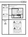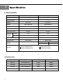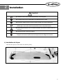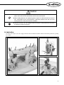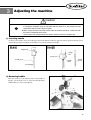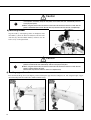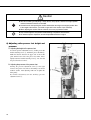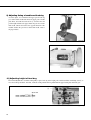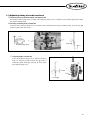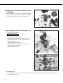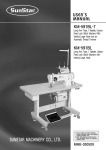
1
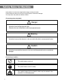
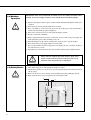
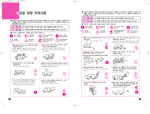
User’s
Manual
KM-815 Series
KM-825 Series
High post, High speed,
one-two needle, sewing
machine
1) For proper use of the machine, thoroughly
read this manual before use.
SUNSTAR MACHINERY CO., LTD.
2) Keep this manual in a safe place for future
reference in case the machine breaks
down.
MME-050509
lity
a
u
tQ
Besst Pricevice
Be st Ser
Be
1. Thank you for purchasing our product. Based on the rich expertise and
experience accumulated in industrial sewing machine production, SUNSTAR
will manufacture industrial sewing machines, which deliver more diverse
functions, high performance, powerful operation, enhanced durability, and
more sophisticated design to meet a number of user’s needs.
2. Please read this user’s manual thoroughly before using the machine. Make
sure to properly use the machine to enjoy its full performance.
3. The specifications of the machine are subject to change, aimed to enhance
product performance, without prior notice.
4. This product is designed, manufactured, and sold as an industrial sewing
machine. It should not be used for other than industrial purpose.
R
SUNSTAR MACHINERY CO., LTD.
Table of contents
Safety rules for machine ...................................................................................................... 4
1. Specification..................................................................................................................... 8
1) Sewing machine .......................................................................................................................................................... 8
2) Clutch motor................................................................................................................................................................ 8
2. Installation ........................................................................................................................ 9
1) Installation of oil pan .................................................................................................................................................. 9
2) Installation of machine head..................................................................................................................................... 10
3) Lubrication ................................................................................................................................................................ 11
4) Adjustment of belt tension........................................................................................................................................ 12
5) Installation of belt cover ........................................................................................................................................... 12
3. Adjusting the machine ................................................................................................... 13
1) Inserting needle ......................................................................................................................................................... 13
2) Removing bobbin...................................................................................................................................................... 13
3) Inserting bobbin ........................................................................................................................................................ 14
4) Routing upper thread................................................................................................................................................. 14
5) Adjusting thread tension ........................................................................................................................................... 15
A. Adjusting the upper thread tension
B. Adjusting the lower thread tension
C. Adjusting the thread take up spring tension
6) Adjusting roller presser foot height and pressure .................................................................................................... 16
A. Adjusting the height of the presser foot
B. Adjusting the pressure of the presser foot
7) Rotating roller shaft .................................................................................................................................................. 17
8) Adjusting stitch length .............................................................................................................................................. 17
9) Adjusting timing of needle and feed dog ................................................................................................................. 18
10) Adjusting height of feed dog .................................................................................................................................. 18
11) Adjusting timing of needle and hook ..................................................................................................................... 19
A. Adjusting clearance between needle and edge of hook
B. Adjusting ascending level of needle bar
C. Adjusting height of needle bar
12) Adjusting clearance between hook and opener ..................................................................................................... 20
13) Exchanging needle width gauge set ....................................................................................................................... 20
4. Causes of Trouble and Troubleshooting....................................................................... 21
1) Sewing machine troubleshooting ............................................................................................................................. 21
Safety Rules for Machine
Safety labels in the manual are categorized into danger, warning and caution.
Failure to follow the safety rules may result in physical injuries or mechanical damages.
The safety labels and symbols are defined as follows.
[The meaning of the safety labels]
Danger
Instructions here shall be observed strictly.
Otherwise, the user will be killed or suffer severe physical injuries
Warning
Instructions here must be observed, or the user could suffer fatal or severe physical injuries.
Caution
Instructions here should be observed, or the user could face physical injuries or mechanical
damages.
[The meaning of symbols]
This symbol means a must-not.
This symbol means a must for safety.
This symbol means that an electric shock may be caused if the
instruction is not followed properly.
4
1-1) Machine
mobilization
Only personnel with a full understanding of the safety rules should move the
machines. The following directions must be observed when delivering the machines.
ⓐ At least two persons should work together.
ⓑ In case the machine should be transported, please wipe the oil covered on the machine to
prevent accidents.
Danger
1-2) Machine
Installation
Caution
Because physical damage such as the functional obstacles and breakdowns are
likely to occur according to the environment in which the machine is being installed.
Therefore, the following preconditions should be fulfilled.
ⓐ Please keep the order from top to bottom when unpacking the package. Especially, mind
that the nail on the boxes.
ⓑ Because machines are apt to be contaminated and corroded by dust and moisture, you
should install the climate controller and should clean the machines regularly.
ⓒ Keep the machines out of the direct rays of the sun.
ⓓ Keep both sides and the backside of the machines off at least 50cm from the wall to secure
enough space to repair.
ⓔ Danger of Explosion. Don’t run the machine near the places with the dangers of explosion.
Don’t run the machine near the places with the dangers of explosion, including the places
where the spraying product like aerosol are used in large quantities or oxygen are dealt
with, unless the exact actions concerning the operation are guaranteed to avoid the
explosion.
ⓕ Because of the peculiarity of the machine, any illuminators are not equipped. So, users
should install the lighting apparatus around the working area.
[Note] The details about the installment of the machine are described in No. 2
Installations.
1-3) Troubleshooting
Danger
In need of troubleshooting, it should be done by the trained A/S engineer of our
company.
ⓐ Ahead of cleaning and repair, be sure to shut off the power supply. And wait for about 4
minutes till the machine discharges completely.
ⓑ Even a part or all of the machine should not be modified without any consultation with our
company.
ⓒ In case of repair, you should change the damaged part into the standard article of our company.
ⓓ After repair, please put again the safety cover disjointed while repairing.
5
1-4) Machine
Operation
Warning
KM-815/825 series are manufactured for industry use to sew textiles and other similar
material. In case of running the machine, users should observe the following things.
ⓐ Ahead of operating the machine, please read the manual and understand fully the details on its
operation.
ⓑ Don’t forget to put on the garment suited for the safe work.
ⓒ Keep your hands or a part of the body away from the running part of the machine like a
needle, hook, thread take-up spring and pulley etc.
ⓓ Don’t remove any kind of cover for safety while running the machine.
ⓔ Be sure to connect the earthed line.
ⓕ Before opening the electric box such as a control box, be sure to shut off the power supply and
make sure that the power switch should be put on “off.”
ⓖ When threading the needle or before checking after sewing, be sure to stop the machine.
ⓗ Don’t switch on the power supply with the foot on the pedal.
ⓘ Don’t run the machine when the cooling fan are not running. Be sure to clean the air filter in
the control box once a week.
ⓙ If possible, keep off from the strong electronic wave like a high frequency welding machine.
Warning
1-5) Safety Device
Warning
Always start the machine with safety covers in place since
fingers or hands could be injured or cut off by the belt. Turn off
the power switch during check-ups or adjustments.
ⓐ Safety Label: Suggestions while running the machine are stated.
ⓑ Thread take-up spring cover: the device to prevent the human body from touching the thread
take-up spring.
ⓒ Belt cover: the device to prevent hands, feet and clothing from getting jammed by the belt.
ⓓ Finger guard: the device to prevent fingers from contacting the needle.
ⓑ
ⓐ
ⓒ
ⓓ
6
1-6) Position of
Caution Mark
CAUTION
경 고
“Caution” is attached to the machine for safety. In case of starting to run the machine,
read the directions of “Cautions” carefully.
[Position of Caution Mark]
Do not operate without finger guard and
safety devices. Before threading, changing
bobbin and needle, cleaning etc. switch off
main switch.
손가락 보호대와 안전장치 없이 작동하지
마십시오.
실, 보빈, 바늘교환시나 청소전에는 반드시
주전원의 스위치를 꺼 주십시오.
CAUTION
경 고
Hazardous voltage will cause injury.
Be sure to wait at least 360 seconds before
opening this cover after turn off main switch
and unplug a power cord.
고압 전류에 의해 감전될 수 있으므로 커버를
열 때는 전원을 내리고 전원 플러그를 뽑고
나서 360초간 기다린 후 여십시오.
1-7) Content of
“Caution”
Caution
CAUTION
경 고
Do not operate without finger guard
and safety devices. Before threading,
changing bobbin and needle, cleaning
etc. switch off main switch.
손가락 보호대와 안전장치 없이 작동하지
마십시오.
실, 보빈, 바늘교환시나 청소전에는 반드시
주전원의 스위치를 꺼 주십시오.
CAUTION
경고
Hazardous voltage will cause injury.
Be sure to wait at least 360 seconds
before opening this cover after turn
off main switch and unplug a power
cord.
고압 전류에 의해 감전될 수 있으므로 커버를
열 때는 전원을 내리고 전원 플러그를 뽑고
나서 360초간 기다린 후 여십시오.
7
1
Specification
1) Sewing machine
MODEL
KM-815
KM-825
HEAVY MATERIALS
HEAVY MATERIALS
1
2
NEEDLE
DP 5 # 19
DP 5 # 19
SPEED
MAX 3,000 S.P.M
MAX 3,000 S.P.M
MAX 5mm
MAX 5mm
NEEDLE BAR STROKE
33.4mm
33.4mm
THREAD TAKE UP
61.5mm
61.5mm
7mm
7mm
11mm
11mm
178mm
178mm
DROP-OILER
DROP-OILER
USAGE
STITCH LENGTH
STITCH WIDTH
ASENDING OF MANUAL
PRESSUER
KNEE LIFT
FOOT
HEIGHT OF POST
LUBRICATION
ROLLER PRESSER FOOT 1/16 ,3/32
GENERAL PRESSER FOOT 1/8 ,3/16 ,1/4 ,3/8
GUAGE
ROLLER PRESSER FOOT
GENERAL PRESSER FOOT
OPTION
SLIDE HOOK COVER
HINGE HOOK COVER
2) Clutch motor
8
MODEL
VOLT
WATT
HERTZ
HEC-1701
ONE PHASE 220V
250W
50/60Hz
HEC-1703
THREE PHASE 220V/380V
250W
50/60Hz
HEC-1705
THREE PHASE 220V
400W
50/60Hz
HEC-1706
ONE PHASE 220V
400W
50/60Hz
2
Installation
Caution
▶ Installation of the machine should be performed by a trained engineer.
▶Any electrical wiring must be performed by a qualified technician or agent.
▶The machine weighs over 41kg. At least 2 persons should carry out the installing work.
▶Plug in after the installation is complete. If the operator mistakenly steps down on the pedal
with the plug in, the machine will start automatically and can cause physical injuries.
▶Connect the ground (earth) wire. An unstable connection may result in an electric shock or a
malfunction.
▶Place the belt cover on top of the machine.
▶Use both hands when bending the machine backwards or returning it to the normal position.
Using only one hand can lead to severe hand injuries due to the weight of the machine.
1) Installation of oil pan
After insert the oil pan① toward a table, fix it with fixing nails②.
①
②
②
[Figure 1]
9
2) Installation of machine head
After fixing the machine head hinge ① into the bed holes with fixing screw② and ③, rubber hinge④, stand the machine on the
rubber hinge and the rubber cushion⑤.
① ③
②
①
⑤
⑤
②
⑤
④
⑤
[Figure 2]
10
Caution
▶Plug in only after oil supply is finished. If the operator mistakenly steps on the pedal with the
plug in, the machine will start automatically and can cause severe injuries.
▶When handling lubricants, wear protective glasses or gloves to avoid contact with your eyes or
skin. Inflammation may be caused otherwise. Never drink lubricants since they can cause
vomiting or diarrhea. Keep out of the reach of children.
▶Operate the machine only after adding oil when the machine is being used for the first time or
has been left unused for a long time.
3) Lubrication
As can be seen in figure 3, be sure to supply oil into the oil holes marked red and the oil holes in the friction parts before operating
the machine.
[Figure 3]
11
4) Adjustment of belt tension
After installing the motor, loosen the fixing nuts ①, ② up and
down and tension will be created to the belt ④ due to motor ③
falling by gravity. Fasten the fixing nut ① initially and then
fasten the fixing nut ② tightly.
[Figure 4]
5) Installation of belt cover
Fix belt cover “A” ① onto the machine body with using three
clamp screws ②. Lay the machine back and it will be easy to
assemble belt cover “A” ①. After the assembling, insert the
front part of belt cover “B” ③ into the groove of belt cover
“A” ① and then fasten the back part of it by using the clamp
screw ④.
[Figure 5]
12
3
Adjusting the machine
Caution
▶Always turn off the power when mounting a needle.
If the operator mistakenly steps on the pedal while the power is on, the machine will start
automatically and can result in physical injuries.
▶When using clutch motor, be aware that the motor will continue to rotate for a while even after
the power is switched off due to inertia.
Start to work on the sewing machine only after the motor has come to a complete stop.
1) Inserting needle
As can be seen in figure 6, move the needle upper end so that it directly touches the upper side of the stopper hole when the groove
of the needle is facing inward. Then, use the fixing screw to fix the position of the needle.
Stopper hole
Stopper
hole
Clamp screw
Needle groove
Needle
groove
Needle
holder
Left and Right
[Figure 6]
2) Removing bobbin
Place the needle ① in the highest position, and then like in
Figure7, open the hook covers ② on the left and right, lift the
bobbin holder ③ to remove the bobbin ④.
③
②
①
④
[Figure 7]
13
Caution
▶Turn off the power when adjusting the lower thread tension.
If the operator mistakenly steps on the pedal, the machine will start automatically and can
cause physical injuries.
▶When using the clutch motor, be aware that the motor will continue to rotate for a while after the
power is switched off due to inertia. Start to work only after the motor has come to a complete stop.
3) Inserting bobbin
Stop the needle ① at the highest position. As in Figure8, insert
the bobbin ② (where the thread is rolled onto) into the hook.
After that, lay down the bobbin holder③ and then, close the
hook cover④ on the right and left.
③
①
④
②
[Figure 8]
Caution
▶Turn off the power switch when routing the upper thread. It the operator mistakenly steps on the
pedal, the machine will start automatically and can cause physical injuries.
▶When using the clutch motor, be aware that the motor will continue to rotate for a while after the
power is switched off due to inertia.
Start to work only after the motor has come to a complete stop.
4) Routing upper thread
Place the thread take-up lever to the highest position and hang the upper thread as in Figure9, 10. The adequate length of upper
thread extending from the needle hole is 50mm for initial sewing.
[Figure 9]
14
[Figure 10]
5) Adjusting thread tension
The result of the needlework depends on the sewing conditions such as the sewing material, used thread and stitch length. So
please adjust as desired.
- good sewing
- upper thread tension is strong while the lower thread tension is weak.
- upper thread tension is weak while the lower thread tension is weak.
[Figure 11]
A. Adjusting the upper thread tension
As in Figure 12, turning the tension adjustment nut of the
thread adjusting device① clockwise makes the upper
thread tension stronger and counterclockwise makes it
weaker.
Weak
Strong
Weak
Strong
[Figure 12]
B. Adjusting the lower thread tension
As in Figure 13, turning the tension adjustment nut ① of the
hook clockwise makes the lower thread tension stronger and
counterclockwise makes it weaker.
Strong
Weak
C. Adjusting the thread take up spring tension
[Figure 13]
a) Adjusting the thread take up spring stroke
As in Figure 14, loosen the fastening screw①, and turn the stopper bushing of the thread take up spring ② clockwise to make
the stroke smaller and counter clockwise to make it bigger. The thread take up stroke is normally 5~10mm.
b) Adjusting the thread take up spring tension
As in Figure 15, insert the driver into the groove① of the thread tension control assembly. Turn clockwise to make the spring
tension stronger and counterclockwise to make it weaker. The thread take up spring tension is normally 50~80g.
[Figure 14]
[Figure 15]
15
Caution
▶After disassembling and adjusting a safety device, always place it back to the original position
and check whether it functions as intended.
▶Use both hands when pushing the machine backward or returning it to the original position. Due
to the weight of the machine, your hand can get stuck in the machine if you should slip.
▶When adjusting the machine with the switch on, be sure to pay extreme caution.
▶Only trained engineers must perform troubleshooting or inspection of the machine.
▶For electrical repair or inspection, consult with qualified technicians or agent.
6) Adjusting roller presser foot height and
pressure
A. Adjusting the height of the presser foot
Loosen the pressure adjustment screw ① and the presser bar
bracket fastening screw ②, and lift the presser bar lifter③.
Make the distance between the upper side of the needle
plate and the lower side of the presser foot 7mm. Then,
tightly fasten the bracket fastening screw②. Be sure that
the presser bar does not move.
Strong
Strong
Weak
Weak
B. Adjusting the pressure of the presser foot
Turning the pressure adjustment screw① to the right
increases the presser foot tension, and turning it to the left
makes it weaker. After adjusting, make sure to tighten the
fixing nut④.
For minute adjustment, turn the auxiliary pressure
adjustment screw ⑤.
[Figure 16]
16
7) Rotating roller shaft
A. Raise the presser bar lifter.
B. Hold the roller presser foot bracket guide ① as in Figure 17
and move it down and left. Then, there will be some space
to exchange the gauge.
①
C. To restart, hold the roller presser foot bracket guide ① and
turn it to the right direction.
[Figure 17]
8) Adjusting stitch length
As in Figure 18, the number marked in the stitch length
adjusting dial① indicates the stitch width by mm. By moving
left or right, set to the desired number.
[Figure 18]
17
9) Adjusting timing of needle and feed dog
As in the figure, it is normal that the upper part of feed dog
goes down and the needle hole meets the upper part of needle
plate. If not, loosen the feed cam screws ① and move the cam
position right and left to the proper match. If gear moves faster
than needle, turn the feed cam to the opposite direction of the
machine rotation. If t gear moves slower than needle, rotate to
the proper match.
[Figure 19]
[Figure 20]
10) Adjusting height of feed dog
The normal adjustment is as follows. Turn pulley to place feed dog at the height point. And loosen lifter crank clamp screw① to
move the crank up and down. After that, make the crank protrude 1mm in parallel with the upper needle plate and fix the gear.
①
About 1mm
[Figure 21]
18
11) Adjusting timing of needle and hook
A. Adjusting clearance between needle and edge of hook
Loosen the hook base clamp screw ① and the lower shaft gear clamp screw ②. And then, move hook base right or left to make
the clearance 0.05mm wide .
B. Adjusting ascending level of needle bar
Loosen the lower shaft gear clamp screw ② and raise needle 2.4mm from the lowest point. When is done, move the gear right
and left to put the edge at the center.
0.05mm
①
①
Hook edge
Hook base clamp screw
2.4mm
[Figure 22]
C. Adjusting height of needle bar
Loosen the needle bar clamp screw ① and move the bar to
make 1~1.5mm the clearance between the upper side of
needle hole and the hook edge. After that, be sure to fasten
the needle bar clamp screw.
①
1~1.5mm
Hook edge
[Figure 23]
19
12) Adjusting clearance between hook
and opener
The normal clearance is as follows. Loosen the opener clamp
screw①. And when the opener ② is pulled to the maximum
level, adjust the clearance between the arrows to 0.2mm.
[Figure 24]
13) Exchanging needle width gauge set
A. The order of disassembly
[Note] Turn off the power
1. Open the hook cover①.
Loosen post cover clamp screw②.
2. Loosen the right and left hook base clamp screw③.
3. Raising the presser lifter, rotate the roller④ right or left.
4. Remove the needle⑤.
5. Disassemble the needle holder⑥.
6. Disassemble the needle guide⑦. (for roller presser foot)
7. Disassemble the needle plate⑧.
8. Disassemble the feed dog⑨.
[Figure 25]
B. Assembly order
After assemble in reverse order of disassembly, fix the right and left hook base. When finish the exchange, implement the
normal adjustment. (page 13)
20
4
Causes of Trouble and Troubleshooting
1) Sewing machine troubleshooting
No
1
2
3
Symptom
Needle
breaks
Thread
breaks
Sewing is
skipped
Checkpoints
Root cause
Corrective action
Direction and
height of needle
Needle is inserted into wrong position
Reinsert the needle correctly
Needle
Needle is bent
Change the needle
Bad timing of feed dog
Adjust the timing of feed dog
Bad timing of needle and hook
Adjust the timing of needle and hook
Needle bar height Bad timing of needle and hook
Adjust the timing of needle and hook
Gap between
needle and hook
The gap between needle and hook is
inadequate
Adjust the gap between needle and hook
Threading
method
Wrong threading
Thread the needle correctly
Needle
Bent needle or broken needle tip
Change the needle
Direction and
height of needle
The direction and height of the needle
inserted is wrong
Insert the needle correctly
Upper thread
tension
Too tight upper thread tension
Adjust the tension of upper thread
Lower thread
tension
Too tight lower thread tension
Adjust the tension of lower thread
Working capacity
of take-up lever
spring
Too much working capacity
Adjust the stroke level
Direction and
height of needle
The position of the needle inserted is
wrong
Insert the needle correctly
Needle
Bent needle or broken needle tip
Change the needle
Threading
method
Wrong threading
Thread the needle correctly
Needle bar
ascending level
Bad timing of needle and hook
Adjust the timing of needle and hook
Needle bar height Bad timing of needle and hook
Adjust the timing of needle and hook
Needle bar
ascending level
Gap between
needle and hook
The gap between needle and hook is
inadequate
Adjust the gap between needle and hook
The length of the remaining upper thread Adjust the adjustment volume of the
upper thread
is too short
The spring is not strong enough to pull
out the lower thread
Adjust the stroke level
The upper
thread does
not rotate
Too tight upper thread tension
Decrease the upper thread tension
Too weak upper thread tension
Increase the upper thread tension
The lower
thread does
not rotate
Tension of upper thread is too weak
Increase upper thread tension
Tension of lower thread is too strong
Decrease lower thread tension
Upper thread
falls out when
starting to sew
Strong upper thread tension
Adjust upper thread tension
Needle is too thick for thread
Check the needle
Thread take up
spring
4
5
6
21