1
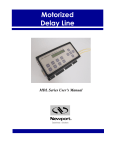
11
1.5 Device Description
1.5.1 General Description
The MDL motorized optical variable delay line consists of three submodules: the variable optical delay module, electronic controller module, and
operation panel (display/keypad) module. Input/output optical signals are
connected to the variable optical delay module via two single mode optical
fibers. The electronic controller carries out the control commands, senses the
delay state, and controls a 2-line, 16-character liquid crystal display (LCD).
There are two interfaces for control command input. As long as
communication between a PC or hand-held device and the MDL is
established, commands can be sent through the built-in RS-232 connector. In
manual control mode, the front panel keypad is used to send the
corresponding control commands. Press any key on the keypad to switch
from remote control to manual control. The delay status and command
information are displayed on the LCD.
1.5.2 Package
The optical delay module, electronic controller, and operation panel are
integrated in a rugged, easy to mount case, as shown in Figure 1. The
electronic controller and display/keypad modules are integrated at the top of
the package. The optical delay module is internally connected to the
electronic controller via a 4-wire ribbon cable.
The input/output optical fiber pigtails and the power switch are mounted on
the left side of the package. The RS-232 and DC power supply connectors are
mounted on the right. The optical input/output can be single mode, or can be
polarization maintaining (PM) fiber to maintain a linearly polarized
input/output state.
External package dimensions of the MDL 330 and 560ps models are shown
in Figure 2.