1
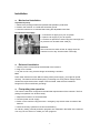
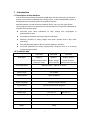
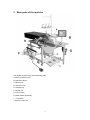
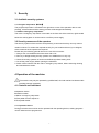
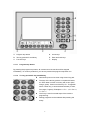
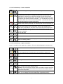
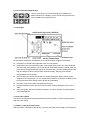
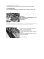
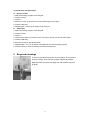
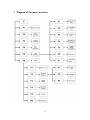
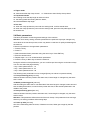
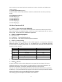
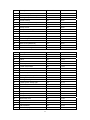
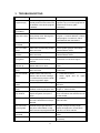
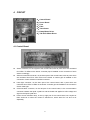
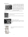
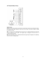
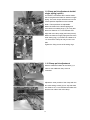
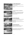
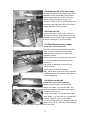
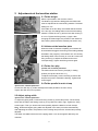
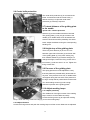
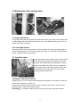
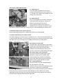
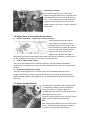
Universal-Flap-Pocket-Machine
Operating instructions
Part 1 Operating instructions
Hint
These operating instructions contain all information required for the operation
of the machine. It adresses to the operator of the machine, that is the person
that works at and with the machine. Please obtain all rules and regulations.
Contents
Page
Part 1 Operating instructions
General security advice and warning hints ...................................................................3
Transportation.......................................................................................................... ........3
Storage...............................................................................................................................3
Installation .........................................................................................................................4
1 Introduction .................................................................................................................5
1.1 Description of the machine............................................................................................5
1.2 Technical data...............................................................................................................5
2 Main parts of the machine..........................................................................................6
3 Security....................................................................................................................... 7
3.1 Available security systems........................................................................................... 7
3.2 Security measures of the operator............................................................................... 7
4 Operation of the machine............................................................................................. 7
4.1 Controls and indicators................................................................................................. 7
4.1.1 Operation device ...................................................................................................... 7
4.1.2 Insertion station....................................................................................................... 10
4.1.3 Mains / emergency stop button............................................................................... 10
4.1.4 Foot pedal machine sequence ............................................................................... 11
4.1.5 Foot pedal stacker................................................................................................... 11
4.1.6 Swing out the folder ................................................................................................ 11
4.1.7 Change folde .......................................................................................................... 11
4.2 Operation ................................................................................................................ 12
4.2.1 Machine sequence ................................................................................................. 12
4.2.2 Program operation…............................................................................................... 12
5 Required cleanings .................................................................................................... 13
2
General security advice and warning hints
1.
Danger might arise for persons, things and environment by inappropriate operation of
this machine. Installation and maintenance duties may only be carried out by
authorized staff.
2.
Before any operations at or with the machine (putting into operation, operation,
maintenance, repair, etc.) the person carrying out has to read and understand this
manual with each appendix completely.
3.
Before carrying out maintenance or repair duties, the mains supply must be cut off.
Additionally pressure must be released from the pneu-matical system.
4.
The machine will be destroyed by a connection to a wrong mains voltage! See the
section ‘Technical data’ before connecting the power supply.
Transportation
Generally it is possible to move the machine. Obey the following hints:
1. Cut off the power supply, release the pneumatical pressure.
2. Fix movable and loose parts.
3. Lift the base with a hoisting device and be sure to lift possible additional devices (e.g.
stacker). If the machine is equipped with transportation casters (option), you will have to
release the brakes at every caster.
4. Move the machine carefully to the new location.
Attention
Attention when moving the machine on sloping areas! Enormous pull power arises from
the machine weight.
Storage
If no other agreement is fixed, the following limitations have to be kept:
1. In closed rooms only.
2. Temperature range -10 ... +45 °C.
3. Humidity max. 80% non-condensing.
Attention
If stored or transported in improper environments, the machine can be damaged severely.
Damages may not be visible from the outside.
3
Installation
z Mechanical installation
Unpack and put up
1. Remove the packing material and possible transportation protections.
2. Position the machine on a solid and horizontal ground.
3. Level the machine to a horizontal stand using the adjustable frame feet.
Connection of air supply
1. Connect the air pipe (A) to your air system.
2. Open the air supply of your air system.
3. Level the air pressure to 6 bar using the control (B); the
air pressure can be read at the scale (C).
Attention
We recommend to switch off the air supply when the
machine is not in duty. Use the black control (B).
z Elektrical installation
1. Use the power cord located at the backside of the machine.
2. Plug it into a socket.
3. Lay the cord in a way, that the danger of stumbling is avoided.
Hint
Parts under electrical current! Without cutting off the power supply, you might be injured
severely. The machine will be destroyed by connecting to a wrong mains voltage! Check,
whether the requirements from chapter ‘Technical data’ meet the local conditions.
Danger to life from unsufficient grounding!
z First putting into operation
This machine has been configured to the individual requirements of the customer. The first
putting into operation can be done easily:
1. Adjust the machine to a horizontal stand.
2. Connect power and air supply.
3. Switch on the machine using the mains / emergency stop switch at the front side of the
machine.
4. Check all security systems for function and efficiency.
As a factory setting, several production programs are contained in the buffer of the machine.
You may use one of them or create your own programs.
4
1
Introduction
1.1 Description of the machine
The Universal-Pocket-Piping-Automaton 5878B allows the automatic piping or slanted of
pockets. The machine is equipped with a cutting device, a clamp transportation system, a
sewing head and a stacking system for the produced pieces.
Machine operation is achieved with an operation device. Here you can open several
control programs, define new programs and check all machine components individually for
maintenance and repair duties.
z
Automatic quick clamp adjustment for easy change from single-piped to
double-piped pockets.
z
Photocells for automatic scanning of flap and welt sizes.
z
Maximum precision of sewing lengths and corner incisions due to step motor
technology.
z
Four standard laser lights for fast and precise loading of the fabric.
z
All pocket parameters are freely programmable. Sequence with up to 6 sewing
programs programmable.
1.2 Technical data
Welt Styles
5878-08B
5878-28B
5878-38B
Single or
Single or
Single or double-
double-straight pocket
double- straight
straight pocket or
with flap or zipper
pocket with flap
slanted pocket with flap
Needle Bite Sizes
Standard 12mm Options 10~24mm
Stitch Density
0.5~3mm
Seam Length
30~240MM
Sewing Speed
2000~3000RPM
Start and End Speed
500~1000RPM
Supply Language
Chinese, English,Indonsia
Cycle Sewing
Up to 6 preset for each program
Marking Lamps
4 standard for positioning of patch piece and flap
Needle Style
MT*190 16#
DP*35R 16#
Electrical Requirements
220 VAC,50/60HZ,single phase,Consumption 0.7kw
Req. air pressure
0.6Mpa
Dimensions
2100 x 1000 x 1450 mm (L x W x H)
Weight
350kg
5
2
Main parts of the machine
The 5878B consists mainly of the following units.
A: Sewing machine head
B: Operation paned
C: Binder unit
D: Clamp foot unit
E: Tab knife unit
F: Stacker unit
G: Power switch
H: Roller stacker (Optional)
I: Foot switch
J: Electric control unit
6
3
Security
3.1 Available security systems
3.1.1 Program stop button(STOP)
The program stop button is mounted in the right down corner of the operation device. After
pressing, all movements and the sewing process will be stopped immediately.
3.1.2 Mains /emergency stop button
The mains / emergency stop switch is mounted on the front side of the machine, right-handed
below the working plate. It can be used to cut-off the power supply.
3.2 Security measures of the operator
The security systems of this machine work passively, that means that they can only react on
certain incidents. To achieve the required security for your health and that of your collegues,
active measures of the operator are required.
Please obey the following general rules for the use of this machine:
1. Always work concetrated and avoid actions with a risk.
2. Don’t try to bridge existing security systems or to disable them in any way.
3. Check all security systems on function and effectivity before starting work.
4. Cut off the power supply before opening the switchbox.
5. Switch off the machine with the mains / emergency stop switch, before executing cleaning
and mainetenance duties.
4 Operation of the machine
This machine may only be operated by qualified staff, who had read and understood this
operating manual completely.
4.1 Controls and indicators
A Operation device
B Insertion station
C Mains / emergency stop button
D Foot pedal machine sequence
E Foot pedal stacker
4.1.1 Operation device
During production the machine can be operated with the operating device; existing programs
can be called and new programmed.
7
A: Program stop button
D: Arrow keys
B: Ten key pad with P-and M-key
E: Enter and back keys
C: Function keys
F: Display
4.1.1.1 Program stop button
By pressing the program stop button, all movements of the machine will be stopped
immediately. To continue production, you have to pressed the program stop button too.
4.1.1.2 Ten key pad with P- key and M/C-key
z
Numerical inputs can be done using the ten key pad.
z
The keys of the ten-key pad are occupied with letters,
too. Each letter is shown on its key with a color (blue,
orange, green). Press one of the keys F1...F3 together
with a number key, to enter the desired letter (F1 blue,
F2 orange, F3 green). Examples: A = F1 + 1; N = F2 + 5;
U = F3 + 7.
z
The P-key is used in several steps of the machine
programming.
z
Sewing programs can be selected after pressing the
M-key.
8
4.1.1.3 Function keys – lower occupation
switches to the upper occupation of the function keys
Tab knife correction; press this key once to change the tab knife position at
the seam start; press twice to change the position at the seam end; after
pressing ENT, enter the new value using the ten key pad, which will be
displayed in the left-handed graphic; 50 =middle value; the higher the value,
the more far the tab knife cuts to the outside. e.g. old value 50, new value
56 and the knife cuts 0.6 mm more to the outside; old value 50, new value
22, the knife cuts 2.8 mm more to the inside
Change pocket length; press F3 and enter the new value for the length to be
sewed; when producing with flap, this sets the photo cell security length, too;
Sewing-over at seam start and end (only valid when sewing with flap); press
once to set the sewing-over at seam start, twice to set it at seam end;
Seam start: the smaller the set value, the more the flap will be sewed over;
seam end: the bigger the set value, the more the flap will be sewed over
Pick needle thread manually; the needle thread catcher will be enabled; until
the key is released
Turn on the lamp
reserved
Reset key; use this key to reset the program sequence step by step; sets the
clamp into starting position
4.1.1.4 Function keys – upper occupation
Press F1 to switch to the upper key occupation. The icons will be displayed in the lower line.
switches back to the lower key occupation
Switch middle knife on/off; the knife is switched off, until it will be switched
on here; together with the middle knife, the mitre knife is switched off
Switch mitre knife on/off; it remains switched off, until it will be switched on
here
Switch stacker on/off; it remains switched off until it will be switched on here
Loading Position
Sets counter to zero
Manual spooling; the sewing head runs with low revs, after a second key
press, it stops in the upper needle position
Attention: At machines with insertion station, the station must be swung out
first in any case, both threads must be removed from the needles and the
spools from the pickers.
Reset spool thread length; when removing a half-full and inserting a full
spool, you can display the whole thread length by pressing this key
9
4.1.1.5 Arrow and Enter/Back keys
Use the arrow keys to move the flashing cursor between the
different sections of a display. Confirm inputs using the Enter key.
Press the Bak-key to leave the menu.
4.1.1.6 Display
All information required for the operation of the machine will be imaged in the display.
z
the graphic on the left side images the mitre cut of the pocket;
z
the graphic to the right shows the seam or flap lenght of the pocket; the value displayed
above the flap (33.3) defines, how far the flap will be pushed behind the needle, after the
photocell has recognized the flap (value for the seam start); the value displayed below the
flap (35) defines, how long the machine continues sewing, after the photocell has
recognized the end of the flap
z
the most upper line shows the number of the selected program (M01) and the seams
assigned to this program (01, 02, 03 ,04,05and 06); seams 01 and 02 are enabled (02 will
be the next seam to be sewed), 03,04,05 and 06 are disabled
z
the name of the current seam is displayed to the right
z
the square below contains the icons of the machine functions assigned to the current
seam
z
below the square, the stock of bobbin thread (57 m) and the number of produced parts
(120) are displayed
4.1.2 Insertion station
The parts to be manufactured are inserted at the insertion station. Use the marking lamps to
align the parts exactly.
4.1.3 Mains / emergency stop button
With the mains / emergency stop button, you can cut-off the power supply of the machine.
10
4.1.4 Foot pedal machine sequence
Use this foot pedal to trigger the steps of the machine sequence (see further below).
4.1.5 Foot pedal stacker
Press the foot pedal stacker to open the stacker to be able to take out the stacked parts.
4.1.6 Swing out the folder
For several reasons (e.g. manual spooling), the
folder must be swung out to get access to the sewing
head. Pull out the locking pin (A) and swing the folder
(B) to the left.
When swinging back, move the folder slowly to the
right until the locking pin
inserts feelable.
Attention:
The folder and the lamps of the crosshair attached to it are adjusted exactly and are sensitive
against violence. Therefore, swing the folder slowly and without the use of power.
4.1.7 Change folder
Different folders are needed for different pocket
shapes (e.g. double/single piping):
1. Open the locking (A) of the folder .
2. Pull the folder towards yourself and downwards to
remove it.
3. Push in the new folder from the bottom side into
the two attachments and
then push it forward.
4. Fix the locking (A).
11
4.2 Operation
4.2.1 Machine sequence
The production sequence is divided into several parts:
1. Machine sequence can start, if the machine is in starting position.
2. Insert the parts to be sewed and align them exactly.
3. Press the foot pedal machine sequence and the clamp comes forward.
4. Press the foot pedal again, the clamp will be lowered.
5. Press foot pedal, the folder is lowered and the fold pushers are driven to the front.
6. Press foot pedal, the flap clamp closes.
7. Press foot pedal, the clamp pushes the part under the sewing head, it will be sewed there,
the mitres will be cut, the clamp opens and the sewed part will be stacked.
The operator can trigger each step with a short pressing of the foot pedal, or run an automatic
process by keeping the foot pedal pressed.
Depending on the programming, different machine sequences might occur.
4.2.2 Program operation
The machine is operated with programs, which can be selected by the operator. A program is
stored at a memory location (e.g. ‘M01’) and contains one or several seams (max. number is
six).
The selected program and the assigned seams are imaged in the upper line of the display. The
machine executes all enabled seams of a program sequentially. An enabled seam is displayed
inverted. You can produce several pocket shapes and lengths sequentially, without changing
the sewing program.
4.2.2.1 Select a sewing program
The current sewing program is displayed in the upper line of the display. How to select a
program:
1. Press M/C-key.
2. Enter the number of the desired program using the ten key pad.
3. Press ENT-key.
4.2.2.2 Enable/disable seams
Seams are assigned to every sewing program. All enabled seams are sewed sequentially.
Enabled seams are displayed inverted.
If a seams shall be skipped, it must be disabled. How to enable/disable a seam:
1. Move the cursor on the desired seam using the arrow keys.
2. Press the ENT-key to enable/disable the seam.
4.2.2.3 Change seam length
Several parameters of the current seam are imaged in the left half of the display (e.g. seam
length, mitre knife position). You can change these settings individually using the function keys.
All changes executed with the function keys are stored for all seams with the same number,
even if they are used in different programs.
Further information are contained in the chapter ‘4.1.1.3 Function keys’.
12
4.2.2.4 Remove and add seams
z
Remove seams
1. Select the sewing program to be changed.
2. Press the P-key.
3. Press F1.
4. Move the cursor on the seam to be removed using the arrow keys.
5. Press the M/C-key.
6. Repeat steps 4. and 5. for all seams to be removed.
z
Add seams
1. Select the sewing program to be changed.
2. Press the P-key.
3. Press F1.
4. Use the arrow keys to move the cursor to the place, where you want to add a seam.
5. Press the ENT-key.
6. Enter the number of the desired seam.
7. Repeat steps 4. to 6. for all seams to be added to the current sewing program.
8. Press the P-key to store the settings and leave the submenu.
5
Required cleanings
To achieve the value and function of the machine, we ecommend
to keep it always clean and free of spare materials and waste.
Blow off threats and cloth rests daily from the machine using the
air pistol.
13
Part 2
Mechanics manual
Hint
This part of the operating instructions contains all information required to put
the machine into operation and to do programming, troubleshooting and
maintenance. It adresses to trained technical personnel, which is able to overview their tasks
and recognize possible danger at an early moment.
Contents
Page
Part 2 Mechanics manual
1 Diagram of the menu structure.......................................................................................15
2 Programming instructions..............................................................................................16
2.1 Create new sewing program...........................................................................................16
2.1.1 Select a M-memory location........................................................................................16
2.1.2 Add seams...................................................................................................................16
2.1.3 Copy seams.................................................................................................................16
2.1.4 Adjust seams...............................................................................................................16
2.1.5 Name seams................................................................................................................17
2.1.6 Delete seams...............................................................................................................17
2.2 Seam functions...............................................................................................................17
2.3 Seam parameters...........................................................................................................18
2.4 Basic parameters............................................................................................................22
2.5 Other Functions..............................................................................................................24
3 Troubleshooting...............................................................................................................26
4 Circuit................................................................................................................ ...............27
4.1 Control Board..................................................................................................................27
4.2 Power Board...................................................................................................................28
4.3 Fuse................................................................................................................ ...............28
4.4 Transformer And Filter....................................................................................................28
4.5 Clamp Motor Driver.......................................................................................... ..............28
4.5 Tab Knife Motor Driver.................................................................................................. .29
14
1
Diagram of the menu structure
15
2
Programming instructions
2.1 Create new sewing programs (P-F1)
The following steps are required to create a new sewing program:
1. Select memory location (Mxx).
2. Add or copy seams.
3. Adjust the seams.
2.1.1 Select a M-memory location
Due to customer-specific configuration, several M-memory locations are occupied by sewing
programs. There are enough memory locations available for new sewing programs.
Select an available memory locationz:
1. Press the M-key.
2. Enter the number of the desired memory location (e.g. 09).
If the memory location is available, seam No. 50 is assigned six times.
2.1.2 Add seams
If existing seams shall be used in the new program, you can remove the seams of the memory
location and add the desired seams like described in part 1 of this manual.
If you want to create new seams, you will first have to assign new numbers to the seams,
which are not used in another program.
2.1.3 Copy seams
If existing seams shall be manipulated for the new program, the seams can be copied to a new
seam number. This allows to keep the original seams unchanged:
1. Move the cursor to the seam number, where you want to copy another seam to (e.g. No.45).
2. Press the P-key.
3. Press F1.
4. Press F2.
5. Enter the number of the seam, which you want to copy (e.g. 10).
6. Press the ENT-key.
Now seam No. 10 has been copied to No. 45, a new number has been assigned. Seam No. 10
and 45 are identic. If you need more new seams, you can assign further seam number to the
program (e.g. 46, 47, 48, a.s.o.) and copy existing seams to these numbers.
2.1.4 Adjust seams
The seams copied to the seam number 45, ... can now be manipulated
without changing the original seams (which are used in other programs).
The following items can be adjusted:
• mitre knife position, seam length, a.s.o.
• seam functions
• seam parameters
• seam name
16
2.1.5 Name seams
To be able to distinguish seams, it is possible to define seam names. Follow this procedure:
1. Press the P-key (opens the menu levels).
2. Press the key F5 (INIT-Parameter).
3. Press the key F1 (enter seam name).
4. The keys of the ten-key pad are occupied with letters, too. Each letter is shown on its key
with a color (blue, orange, green). Press one of the keys F1...F3 together with a number key,
to enter the desired letter (F1 blue, F2 orange, F3 green). Examples: A = F1 + 1; N = F2 + 5; U
= F3 + 7.
5. Press the arrow keys to switch to the next or prior letter.
6. Press the P-key to terminate the entering and save the seam name.
2.1.6 Delete seams
An existing seam can be deleted.
ATTENTION: If a seam is used in several programs, it will be deleted in all programs. The
deletion of a seam can not be undone.
1. Press the P-key.
2. Press F5.
3. Press F5.
4. Enter the number of the seam to be deleted.
5. Press the P-key to delete the seam.
2.2 Seam functions (P-F2)
Center knife
cuts the pocket between the seams; if the center knife is
disabled,the mitre knife will be disabled utomatically
Tab knife
cuts the pocket edges; if the center knife is disabled, the tab
knife will be disabled, too
Stacker
stacks the sewed parts automatically
Vacuum
keeps the parts in the insertion station, until the main clamp is
(option)
closed
Vylene
automatic supply with vylene
(option)
Stamp
fixes the parts in the insertion station (3rd hand)
Piping blowing
piping is blown to the folder, to prevent a snapping during
(option)
insertion; should be enabled sewing thin parts
Folder Down
Folder have pressure between the seam
between Seam
Flap clamp left
necessary if additional parts to the piping are inserted (e.g.
pocket bag, facing strips)
17
Flap clamp right
like flap clamp left (see above)
Seam shape
breast welt production; left seam longer than right one
trapeze jacket
Seam shape
left needle shorter than right one
trapeze troucers
Seam form
both needles work parallel
parallel
Seam shape
left seam with offset to the right one
sloping pocket
right
Seam shape
left seam with offset to the right one; mirrored to the right
sloping pocket
sloping
left
Piping pulling
turns the overlap of the piping (only during piping)
through(option)
Photo cell left
necessary during sewing of left flap
Photo cell right
necessary during sewing of right flap
Positioning point
calculation point for the seam start during sewing without flap
front
Positioning point
calculation point for the seam start during sewing without flap
middle
Positioning point
calculation point for the seam start during sewing without flap
rear
Zipper scissor
during sewing an endless zipper, this function gives a
stopcommand to the machine to allow the cutting of the zipper
Seam
Tack length at seam start and seam end
backtacking
Stitch
Stitch length at seam start and seam end。
condensing
2.3 Seam parameters
Several seam-depending machine processes can be set:
1. Press the P-key.
2. Press F3.
3. Select the desired seam parameter using the arrow keys.
4. Press ENT-key.
5. Enter the desired value.
18
6. Repeat steps 3. to 5. for all desired seam parameters.
7. Press the P-key or Back-key to leave the submenu.
During the selection of the parameters, you can scroll line per line using the vertical arrow keys.
You can also select the pages directly:
• Key 0: seam parameters 01 - 15
• Key 1: seam parameters 10 - 24
• Key 2: seam parameters 20 - 34
• Key 3: seam parameters 30 – 35
The seam parameters listed below can be changed. The factory-set default configuration are
shown in square brackets [ ], the possible settings in rounded brackets ( ).
1 Change positioning point 135/225/315 mm
the set value defines the relation point of the seam
2 Insertion speed [80%] (10-90%)
clamp speed from the insertion position to the sew start position; when photo cell is active,
speed will be halved to allow a more exact scanning;
3 Revs seam start [750 rpm] (500 - 1000 rpm)
sewing head revs freely selectable, depending on needle- and center knife setting
4 Revs during seam [2000 rpm] (2000 - 3000 rpm)
freely programmable
5 Revs at seam end [750 rpm] (500 - 1000 rpm)
freely programmable
6 Stitch of seam start revs [5] (1 - 20)
stitch with the revs of parameter 3
7 Stitch of seam end revs [5] (1 - 20)
stitch with the revs of parameter 5
8 Condensation stitch length [1mm] (0.5 – 1.5 mm)
stitch length at seam start or seam end for stitch condensation
9 Stitch length [2.5 mm] (2.0 – 3.5 mm)
10 Tack stitch length [1.0 mm] (0.5 – 3.5 mm)
stitch length at seam start or seam end for tack stitch
11 Condensation stitch number seam start [5] (0 - 10)
number with condensation stitch of parameter 8
12 Condensation stitch number seam end [5] (0 - 10)
number with condensation stitch of parameter 10
13 Tack stitch number seam start [5] (0 - 10)
if this value is set to 0, stitch condensation will be sewed automatically
14 Tack stitch number seam end [5] (0 - 10)
if this value is set to 0, stitch condensation will be sewed automatically
15 Enable center knife [8mm] (1 - 30 mm)
depending on seam and knife width, the center knife should cut est. 1 mm further than the tab
knife
16 Disable center knife [7mm] (1 - 30 mm)
depending on seam and knife width, the center knife should cut est. 1 mm further than the tab
knife
19
17 Thread monitor on after [5mm] (0 - 99 mm)
distance after which the thread monitor will be enabled;
18 Thread monitor filter [7%] (0 – 99%)
the smaller the digit, the more sensitive the upper thread monitor reacts; 99: thread monitor
disabled
19 Slope at seam start [3] (0 - 10)
seam offset (difference left/right needle) at seam start
20 Slope at seam end [3] (0 - 10)
seam offset at seam end
21 Terminal sewing sendlength [0mm] (0 – 9.9 mm.)
22 Intermediate stop selection + pos. [0 cm] (0 - 48 cm]
enter a position, where the main clamp shall be driven to after stacking
23 Clamp up position [off] (on/off)
on = work piece is driven to the insertion station
24 Revs center knife [60%] (10 - 75%)
definition of the cutting speed
25 Revs final roller [99%] (10 - 99%)
a reduction achieves an optimized positioning for the stacking
26 Flap clamp mode
In the control, you can switch on/off the left or right flap clamp and select one of four modes
additionally; dependant on the selection, the flap clamp behave different. In the following table,
the mode number is shown in the first column, the behaviour of the flap clamps is indicated
with graphics.
left clamp closed
right clamp closed
left clamp open
right clamp open
Left and right flap clamp switched on:
00,02,03
01
Insertion position
Insertion position
automatic with folding slide
Left flap clamp switched on, right switched off:
00
Insertion position
with foot pedal pressure
01,03
Insertion position
automatic with folding slide
with foot pedal pressure
02
Insertion position
automatic with folding slide
with foot pedal pressure
20
Left flap clamp switched off, right switched on:
00
Insertion position
with foot pedal pressure
01,03
Insertion position
automatic with folding slide
with foot pedal pressure
02
Insertion position
automatic with folding slide
with foot pedal pressure
Both flap clamps switched on:
00
Insertion position
with foot pedal pressure
with 2nd foot pedal pressure
01
Insertion position
automatic with folding slide
with foot pedal pressure
02
Insertion position
automatic with folding slide
with foot pedal pressure
03
Insertion position
with foot pedal pressure
27 Folding slide mode
both: left + right fold slider enabled
left: left fold slider enabled
right: right fold slider enabled
28 Vacuum mode (option)
off: vacuum disabled
on: vacuum enabled
29 Main clamp mode
both: main clamp left/right down and tight
left: main clamp left down and tigh
right: main clamp right down and tight
none: main clamp both weak, before insertion both tight
30 Stacker mode
roller: only final roller
stacker: only folding stacker
both: folding stacker and final roller
31Clamp carriage return safety photocell
on: the premover photocell is activeated by the work piece
off: the premover photocell is deactivated
32 Folder as stamp [00] (00 - 01)
off: normal insertion process enabled
on: with the first step on the foot pedal, the folder is lowered and fixes the work piece; next step
drives main clamp to insertion position; after clamp is closed, the folder is pushed up to allow
the insertion of the vylene;
33 Flap clam mode
manual: flap clamp active with foot pedal
auto: flap clamp automatically active
21
34 Zipper mode
00: folder down after flap clamp closed
01: folder down when left flap clamp closed
35 Flap dectect mode
00:according as set the flap length to detect trim size
01: the sewing head start sewing after the detect;
02:automated detect flap length
36 Run fast
on: when the clamp pushes the part under the sewing head, it will be sewed there.
off: when the clamp pushes the part under the sewing head, press the foot pedal again, it will
be sewed there.
2.4 Basic parameters
The basic parameters contain the general settings of the machine.
Attention: As a factory setting, the basic parameters are optimized. Improper changes may
cause faults in the machine process, which may lead to a reduction of quality and damages to
the machine.
Follow this procedure to changes basic parameters:
1. Press the P-key.
2. Press F4.
3. Select the desired basic parameter using the arrow keys. Press ENT-key.
4. Enter the desired value.
5. Repeat steps 3. to 5. for all desired basic parameters.
6. Press the P-key or Back-key to leave the submenu.
During the selection of the parameters, you can scroll line per line using the vertical arrow keys.
You can also select the pages directly:
• Key 0: basic parameters 01 - 15
• Key 1: basic parameters 10 - 24
• Key 2: basic parameters 20 – 28
The following basic parameters can be changed [factory-set values in square brackets]:
01 Front positioning point [135 mm]
distance between insertion position and seam start; if seam length is changed only the seam
end is varied
02 Middle positioning point [185 mm]
with this setting the seam start is calculated that if the seam length is changed, seam start and
end are delayed the same; is used for back pocket with dart, if dart shall be positioned in the
middle of the pocket
03 Rear positioning point [235 mm]
distance between insertion position and seam end; if seam length is changed, only the seam
start is varied
Attention: This parameter defines the end of the main clamp. If this parameter is set too large,
there may be sewing problems while sewing flaps.
04 Folder up after [335 mm]
time of the folder lifting after the seam; if distance too short, folder gets caught by the fold
pushers
22
05 Thread length full spool [38 m]
a wrong thread length leads to incorrect values in the display of remaining thread
06 Clamp up after tab cut [0.1s]
Clamps up after tab knife cut.
07 Main sewing length correction [50] 50 =middle value;
08 Work piece send length correction [50] 50 =middle value;
09 Time after clamp down [0.3s]
time delay between clamp down and next operation
10 ‘Thread clamp open’ at seam start [2]
after the first two stitches the upper threads should be released from the thread clamp; after
the time defined here, the thread clamp opens
11 ‘Thread clamp open’ – duration [0.4s]
duration of ‘thread clamp open’ at seam start
12 Cut til upper thread [0.13s]
time for catching and cutting of the upper thread
13 Upper thread cutting time [0.13s]
length of the threads after upper threads picked up
14 Scissor cutting time [0.05s]
influences the zipper scissor to cut the zipper completely before moving to the end position
15 Drive to cutting [80%]
percentage of the clamp speed used by the main clamp to drive to the mitre knifes
16 Mitre knife distance [38mm] (For 5878-28B)
distance between the mitre knifes
Needle gauge [12mm] (For 5878-38B)
distance between the needle
17 Mitre knifes cutting time [0.03s]
cutting time of the mitre knifes
18 Main clamp open [0.01s]
open the main clamp after mitre cutting; if time’s too short, the work piece may slip out of the
machine before taken by the stacker
19 Pick up work piece [0.99s]
After the tab cuts, the amount of time the clamps lift and the stacker
20 Flap send to sewing position [35mm]
Distance from the flap sensor to the needle
21 Flap main sewing length correction [50] 50 =middle value;
22 Clamp speed [90%]
speed of the main clamp to the insertion position
23 Process step-by-step [00]
enter 01 to enable the switching of all machine functions
24 Remaining thread counter on/off [00] (option)
function can be enabled and disabled; 01 = remaining thread monitoring on;
25 Thread cutter revs [250 Rpm]
positioning revs for threat cutting systems
26 Thread cutter position [45] (01 - 59)
23
start correction threat cutter impulse; the smaller the number, the earlier the bobbin threat
cutter is started
27 Threat cutter duration [0.02s.]
duration of bobbin threat cutter should be minimized, otherwise the main clamp is already
driving
28 Flap detect error [5mm]
29 Laser lamp 1 [on]
30 Laser lamp 2 [on]
31 Laser lamp 3 [on]
32 Laser lamp 4 [on]
33 Laser lamp 5 [on]
2.5 Other Functions P-F6
z P-F6-F1:Input service code (AAAAAA)
Press “F1” and press “1” for six times continuously at the same time, and then press “ENT”.
Note: Other menu and related functions of P-F6 can only be performed after the input of
service code. This function is for maintenance application.
z P-F6-F2:Additional programs
F1:Mechanics code
F2:Languages: Chinese/English/Indonsia
F3:Part counter:The number of total work piece is showed
z P-F6-F3:Addon Setting
Note: The menu below is applied to start related program of newly-used mechanical
attachment device, i.e. change “off” into “on” on related ones. If no mechanical attachment
device as below is installed, please select “off” on related menu, otherwise, the machine would
implement wrong operation.
No.
z
Option
State
01
Zipper Scissor
OFF
02
Vylene
OFF
03
Vacuum
OFF
04
Discret Needle Bar
OFF
05
Angled Tab Knife
OFF
06
Welt Turner
OFF
P-F6-F4:Parameters Backup
(Reserve.)
z P-F6-F5:I/O test
All inputs with their numbers will be displayed in the upper half of the display.The inputs
displayed inverted are currently active. All outputs with their numbers are displayed in the
lower half of the display. The outputs displayed inverted are currently active.
You can now select an output using the arrow keys and activate or deactivate it by pressing
the ENT-key. If you press the ENT-key longer than two seconds, the output switches between
active and de-active, unitl you press the ENT-key again (shortly).
The following inputs and outputs are available in this machine.
24
Input
Description
Sensor No.
Connected
01
Dart stretcher up
01
SE01
02
Stack sensor(MA20*160)
02
SE02
04
Patch guide position
04
SE04
05
Center knife up
05
SE05
06
Stack sensor(MA20*160)
06
SE06
07
Folder down
07
SE07
08
Clamp at front
08
SE08
09
Clamp return safety photocell
09
SE09
10
Front tab knife
10
SE10
11
Back tab knife
11
SE11
12
Mitre knife together
12
SE12
13
Photocell right
13
SE13
14
Photocell left
14
SE14
16
Stack sensor(MA25*50)
16
SE16
19
Thread monitor left
19
SE19
20
Thread monitor right
20
SE20
output
Description
Valve No.
Connected
01
Stack
01
EC01
02
Roller motor
02
EC02
03
Stack
03
EC03
04
Stack
04
EC04
05
Folder upwards
05
EC05
06
Folder downwards
06
EC06
07
Center knife motion
07
EC07
08
Tension release
08
EC08
09
Main clamp left
09
EC09
10
Pocket pouch clamp left
10
EC10
11
Folding slide left
11
EC11
12
Folding slide right
12
EC12
13
Pocket pouch clamp right
13
EC13
14
Roller down
14
EC14
15
Center knife actuator
15
EC15
16
Bobbin threat cutter
16
EC16
17
Clamp motor reset
17
EC17
18
Clamp motor direction
18
EC18
19
Clamp motor pulse
19
EC19
20
Mitre knife front
20
EC20
21
Mitre knife back
21
EC21
22
Top threat catcher
22
EC22
23
Dart stretcher
23
EC23
24
Main clamp righ
24
EC24
25
3
TROUBLESHOOTING
Error message
Circumstances
Recommended actions
Error 01: Sewing
program empty
current sewing program is empty,
possibly distances and values are
not entered or the whole program
is deleted
enter program values manually if
required; copy from other programs or
load from the memory (INIT
parameter)
Error 02: Seam
not enabled
current seam not enabled;
Press ENT-key to enable the seam
Error 08: Main
clamp at the stop
limitation switch SE08 switched
during clamp move, although the
clamp is at a distance
check distance counter using the test
program ; if counter defective, change
clamp engine, if counter ok, check
both switches and connections
Error 10: A piece
is inserted
push back barrier is not lighted
check photo cell and film
Error 17: Folder
not up
folder hasn’t reached top position
within error time
check cylinder, gauges, termination
switches EC05, EC06
Error 18: Folder
not down
folder hasn’t reached position
within error time
check cylinder, gauges, termination
switches EC05, EC06
Error 20: Knifes
not together
the mitre knife hasn’t reached
start position before sewing
insertion
check termination switch SE11, check
connection to mitre knife engine
Error 21: Center
knife not up
Center knife couldn’t reach top
position within error time
check cylinder , termination switch
EC07
Error 24: Scissor
not up
scissor couldn’t reach top position
within error time
Check air pressure or mechanical
malfunction
Error 34: Needle
not up
needle couldn’t reach the top
position; with the error message
the control tries to put the needle
into the top position again
1、 press ENT to return
2、 check signal wire
position
Error 35: Thread
broken
threat monitor detects breakage
adjust the tension of thread; get rid of
the burrs
Error 36: Spool
empty
mode ‘Bottom thread counter’
enabled; remaining length is zero
change bobbin thread; reset the
length of bobbin thread
Error 37: Spool
only residual
one of the photo cells at the spool
capsule is lighted, the spool is
empty
if both spools are not empty, one
photo cell reflects the thread and must
be set smaller
Error 41: No flap
automatic flap legth detection with
phot cell is enabled but no flap is
detected
insert flapcheck photo cell SE13 or
SE14 and film
Error 42: Photo
cell not lighted
automatic flap length detection
with photo cell enabled; no flap
within the security length detected
program a longer security length
switch off supervision. check photo
cell SE13 or SE14 and film
Error 54: Station
not locked
folder station not locked
lock stationcheck termination switch
SE04
Error 127:
service code not input
press P-F6-F1 and input service code
(AAAAAA)
26
for
upper
4
CIRCUIT
A:Control Board
B:Power Board
C:Fuse
D:Filter
E:Transformer
F:Clamp Motor Driver
G:Tab Knife Motor Driver
4.1 Control Board
z
Sensor connector, on the up part of the control board, with 25 ports which are numbered
from SE01 TO SE25 on the board. A number pipe is installed on the connection of each
sensor accordingly.
z
Solenoid controlled connector, on the down part of the control board, with 25 ports which
are numbered from EC01 from EC25 on the board. A number pipe is installed on the
connection of each solenoid controlled connector.
z
Laser light connector, on the down part of the control board, with 5 ports which are
numbered from LED1 to LED5 on the board. A number pipe is installed on the connection
of each laser light.
z
Communication connector, on the left part of the control board, is the communication
connector between the liquid crystal box and the board and applied to offer voltage and
signal to the liquid crystal box.
z
Power source indication lamp, on the up right part of the control board, two couples of
them would be on when the current is switched on, which stand for +5V and +3.3V
separately.
27
4.2 Power Board
The function of power board is to convert the
alternating current output by the transformer into
direct current. The left connector on the board is the
input connector of the alternating voltage and
connects with the yellow output wire of the
transformer. The connector on the up left part is the
laser lamp connector and offers +5V direct current to
the lamp. The up right connector is the output
connector of the direct voltage and offers +24V and
+5V direct current to the board.
There is a fuse on the board, so please check that it is off when no voltage is output.
4.3 Fuse
Fuse type and Location: When fuse fuesd, find out the cause and fix it
before replace the new one.
CAUTION: Turn off the power and wait 10 minutes before opening box
cover.
4.4 Transformer And Filter
Transformer:AC 220V ~ AC 24V
Filter:The function of the filter is to minimize the solenoid
interference and improve the efficiency of the input
voltage.
4.5 Clamp Motor Driver
Status indicators(LED) indicate operating states and any
malfunctions.
28
4.6 Tab knife Motor Driver
Signal inputs:
PULSE: Square-wave pulses must be fed to the pulse input to set the motor shaft into rotation.
Each positive pulse edge makes the motor move by one step. The sense of rotation is preset
by the direction input.
DIR: If the signal input is deenergized, the motor turns in a clockwise direction as seen from
the front towards the motor shaft. If the signal input is energized, the motor turns in a
counterclockwise direction.
MF: The motor phase current is switched off when the signal input is energized. The stationary
motor then has no holding torque.
29
Part 3 Technical manual
Hint: This Technical manual contains information for the further maintenance, adjustment and
troubleshooting. It adresses axclusively to trained and experienced technical staff, which is
able to assess the tasks and recognize possible danger at an early moment.
Contents
Page
Safety instructions...............................................................................................................31
1 Clamp adjustment............................................................................................................ 31
1.1 Clamp drive belt.............................................................................................................. 31
1.2 Adjust axial free play of the clamp....................................................................................32
1.3 Parallelity of the clamp arms to the sewing head............................................................. 32
1.4 Lateral adjustment of the double piping........................................................................... 32
1.5 Lateral flap adjustment......................................................................................................32
1.6 Adjust main clamp height................................................................................................. 33
1.7 Adjust main clamp pressure............................................................................................. 33
1.8 Main clamp pressure distribution...................................................................................... 33
1.9 Clamp quick adjustment double/single piping………….................................................... 34
1.10 Clamp quick adjustment................................................................................................. 34
1.11 Adjust folding slide path................................................................................................. 35
1.12 Adjust parallelity of folding slide..................................................................................... 35
1.13 Adjust folding slide......................................................................................................... 35
1.14 Flap clamp position........................................................................................................ 35
1.15 Opening path of the flap clamp...................................................................................... 36
1.16 Photo cell foil...................................................................................................................36
1.17 Check/change clamp rubber.......................................................................................... 36
1.18 Adjust clamp path........................................................................................................... 36
2 Adjustments at the insertion station…............................................................................ 37
2.1 Folder height..................................................................................................................... 37
2.2 Initiator at the insertion plate…......................................................................................... 37
2.3 Folder free play................................................................................................................. 37
2.4 Folder parallel to main clamp............................................................................................ 37
2.5 Adjust piping width............................................................................................................ 37
2.6 Center knife protection...................................................................................................... 38
2.7 Lateral distance of the guiding plate to the needle............................................................ 38
2.8 Height stop of the guiding plate......................................................................................... 38
2.9 Pressure of the guiding plate............................................................................................ 38
2.10 Adjust marking lamps...................................................................................................... 38
3 Adjustments at the sewing head...................................................................................... 39
3.1 Height adjustment............................................................................................................. 39
3.2 Lateral adjustment.............................................................................................................39
3.3 Top threat cutte................................................................................................................. 39
3.4 Height of top threat catcher............................................................................................... 39
3.5 Center knife adjustments.................................................................................................. 40
3.6 Adjustments of the bobbin threat catcher.......................................................................... 41
3.7 Adjust piping detection...................................................................................................... 41
3.8 Adjustments at the mitre knifes......................................................................................... 42
30
Safety instructions
Many of the measures described in this manual can be executed at a machine powered-off
and with released air-pressure. Please obtain the switch-off procedures described below.
Some of the measures described in this manual can only be executed, if the machine is under
electrical power or air pressure.
<power off> machine must be cut off the power supply
<release pressure> pneumatic pressure must be released from the machine
Cut off power supply
Use the mains/emergency stop switch to switch off the machine. Cut off the power supply and
assure that it can’t be restored unintentedly.
Release pneumatic pressure
Close the air supply with the black switch at the air supply unit. Cut the machine from the air
supply and assure, that it can’t be restored unintentedly.
1 Clamp adjustment
The following assemblies must be distinguished in the clamp area:
1. Clamp motor
2. Clamp carriage
3. Clamp drive belt
4. Clamp arms
5. Main clamp
1.1 Clamp drive belt
The clamp must stand in home position (like shown in
the upper picture).
The drive belt (1) must have enough tension that it
gives about 15 mm when loaded with 1 kg (in the
middle between both belt disks).
If required, loosen both fixing screws (2) and adjust the
set screws (3). Tighten the fixing screws (2) again.
31
1.2 Adjust axial free play of the
clamp arms
<power off> <release pressure>
The clamp arms (1) must be adjusted
without free play.Although they have to
move easily.
Check the correct adjustment from time to
time. If required, you can adjust the axial
free play of the clamp arms with the screws
(2).
1.3 Parallelity of the clamp arms
to the sewing head
This is adjusted in the factory and doesn’t
have to be changed.
1.4 Lateral adjustment of the
double piping
<power off> <release pressure>
Insert the folder for the double piping.
The distance between the inner side of
the main clamp and the sole edge at the
folder shall be 1.5 mm on the right and
left side.
This distance can be adjusted with the
setting rings (1).
1.5 Lateral flap adjustment
<power off> <release pressure>
Insert the folder for single piping.
There should be a distance of 1.5 mm
between the inner side of the clamp and
the sole of the folder.
This can be adjusted with the two outer
setting rings (1).
32
1.6 Adjust main clamp height
The main clamp height in insertion position
must be 30 mm.
To adjust this, loosen the nuts (1) at both clamp
pressure cylinders and turn the piston pole (2)
until the must height is present.
1.7 Adjust main clamp pressure
The clamp pressure must be 3.5 bar. You can
read it at the pressure gauge (1) on the clamp
carriage.
To adjust the pressure, pull out the black knob
and turn it into the required direction. Press the
knob down again.
1.8 Main clamp pressure distribution
An even pressure must be over the whole main
clamp area.
Drive the main clamp into insertion position and
lay thin sewing material under the clamp arms.
Close the main clamp (control: check outputs).
Pull the sewing material laterally and check the
even clamp pressure.
If required, you can adjust the pressure
distribution. Loosen the fixing screws (1) of the
two allen screws (2). Turn the two allen screws
(2) until the correct pressure distribution is
present. Tighten both fixing screws (1) again.
33
1.9 Clamp quick adjustment double/
single piping (option)
An initiator is mounted at the insertion station,
which recognizes the folder for double or single
piping. The main clamps will be driven into the
correct position dependant on the inserted
folder. These positions are adjustable.
Mount the folder for the double piping and
move both inner setting rings (1) in a way that
there is a distance of 1.5 mm between sole
edge and main clamp edge (see lower picture).
Mount the folder for single piping and move the
outer setting ring (1) until there is a distance of
1.5 mm and the clamp can only move to one
side.
Tighten the fixing screws of all setting rings.
1.10 Clamp quick adjustment
With the additional initiator at the folder (1) a
valve for the additional clamp move is
controlled.
Adjuste the outer position of the clamp with the
two outer setting screws (2) in a way that there
is a distance of 1.5 mm between the folder sole
and the inner side of the main clamp.
34
1.11 Adjust folding slide path
<power off> <release pressure>
The distance between the folding slide (1) driven in
and out must be 5 mm.
If required you can adjust the setting screw (2) at the
cylinder (3).
1.12 Adjust parallelity of folding slide
<power off>
In driven in state, the folding slide must be parallel to
and 0.5 mm away from the edge of the main clamp.
This can be adjusted with the fixing screws of the
folding slide cylinder (1).
1.13 Adjust folding slide
<power off> <release pressure>
A turn movement of the folding slide must be assured
which allows him to adjust to the strength of the
sewing material.
Adjust the screws (1) to adjust the folding slide with no
free play axially.
1.14 Flap clamp position
<power off> <release pressure>
The flap clamps must stand in a distance of 5 mm
parallel to the inner side of the main clamp.
To adjust the flap clamp, loosen the fixing screws (1)
of the flap clamp beam. Adjust the flap clamp correctly
and tighten the fixing screws (1) again.
35
1.15 Opening path of the flap clamp
The opening path of the flap clamps (4) must be
adjusted in a way that the flap clamp presses
with its complete length onto the main clamp,
when the flap clamp cylinder is driven out.
Loosen both allen screws (1) at the flap clamp to
be adjusted and adjust the cylinder (2) correctly.
Tighten both allen screws (1) again.
1.16 Photo cell foil
A photo cell foil (5) is fixed to each clamp (3).
This allows an always good detection of the flap.
Clean the foil with a clean cloth from time to time.
If the foil is damaged, it must be changed.
1.17 Check/change clamp rubber
<power off> <release pressure>
There are moss-rubber strips below each main
clamp. If there are problems of the sewing
material and the clamp, these rubber strips
should be checked.
Demount the clamp by loosening the allen screw
(1). The moss rubber strip is fixed with three
screws (2).
If the rubber is damaged, loosen them and
change the strip.
Fix the clamp arm again and adjust it.
Hint:When working with thick sewing material it
is advantageous to use a thicker clamp rubber or
mount a heightening.
1.18 Adjust clamp path
Adjust front stop <release pressure>
Drive the clamp carriage (1) into insertion
position intil initiator 1 (2) switched dark. The
distance (A) between the beam and the clamp
carriage must be 19 mm.
To adjust the distance, loosen the fixing screws
of the initiator 1 (2) and move him in the desired
direction. Tighten the fixing screws again.
Loosen the fixing screw of the stopping rubber (3)
and turn this in or out, until there is a distance (B)
of 3 mm to the clamp carriage. Tighten the fixing screw again.
36
2
Adjustments at the insertion station
2.1 Folder height
Select output 05/06 in the machine control.
The distance (A) between sliding plate and folder sole
must be adjusted to the used sewing material. The basic
setting is 2 mm.
If the folder is set too deep, the material will be blocked.
If it is too high, the folding slides cannot fold the sewing
material. Loosen the nut (1) and turn the allen screw (2)
in or out. Tighten the fixing screw (1) again. After
changing the folder height, the position of the initiator at
the insertion plate should be checked (see section 2.2).
2.2 Initiator at the insertion plate
When the folder is lowered completely, this initiator will
be switched and triggers the closing of the folding slides(if
activated in the program). If the initiator isn’t set correctly,
the folding slides come too early or not at all. Loosen the
fixing screws (1) to adjust the initiator and move it
correspondingly. Tighten both fixing screws again.
2.3 Folder free play
<power off> <release pressure>
The folder should not have any free play in folding
position (see picture at section 2.1).
To adjust the free play, loosen the fixing screws at the
stop bar and push it towards the bearing. Tighten both
screws again.
2.4 Folder parallel to main clamp
<power off> <release pressure>
Loosen the allen key (4) a little and adjust the folder parallel to the main clamp.
Tighten the allen key in this position.
2.5 Adjust piping width
<power off> <release pressure>
To adjust the piping width, loosen both fixing screws (4) at the clamp block. Tilt the clamp
block with the help of the setting screw (3) a very little to the left or right. Tighten the fixing
screws again. Then you should check and possibly adjust the distance to both clamps.
Hint:Double and signle piping width are adjusted in the same procedure automatically.
After adjusting the folder, the positions of the marking lamps must be checked and possibly
adjusted.
The folder sole width is decisive for the piping width. It can be changed if desired by the
customer.
37
2.6 Center knife protection
<power off> <release pressure>
The center knife protection (2) is mounted at the
folder. It should surround the center knife (1)
without touching it. Adjust the center knife
protection (2) carefully if required.
2.7 Lateral distance of the guiding plate
to the needle
<power off> <release pressure>
Distance (A) to the needle should be minimized.
The guiding plate (1) may not get contact to the
needle (2) or needle head, since otherwise there
would be loud noise and the possibility of a threat
break. Adjust the distance using the corresponding
bending tool.
2.8 Height stop of the guiding plate
There may be a distance (A) of max. 0.5 mm
between upper side of the sole (2) and lower side
of the guiding plate (3). Only when sewing very
thick material, distance (A) must be enlarged. To
change the height, loosen the fixing screws of the
two screws (1) and turn them in or out. Tighten the
fixing screws then.
2.9 Pressure of the guiding plate
The spring pressure must be adjusted in a way
that both plates are pressed safely downwards at
any time. If the pressure is too low, a needle break
can appear during the front tack. If the pressure is
too high, the flap will be pushed back at seam start.
Turn both settings screws (4) until enough
pressure is present at the guiding plates.
2.10 Adjust marking lamps
2.10.1Adjust parallelity
The middle axis of the light crosses of the marking
lamps must be on the middle cut exactly.
Loosen the fixing screw (5) to adjust the marking
lamp. Loosen the fixing screw in the ring (4) to turn the marking lamp.
2.10.2Adjust distance
Loosen the fixing screws and push the marking lamps until the correct distances are adjusted.
38
3 Adjustments at the sewing head
3.1 Height adjustment
The ground plate of the sewing head must be leveled with the upper edge of the working table.
To adjust height and horizontal level loosen the nuts (1) and adjust them by turning in or out.
Tighten the counter nuts again.
3.2 Lateral adjustment
The stitch plate (2) of the sewing head (1) must be exactly in the gap of the sliding plate (3).
Loosen the fixing screws in the mounting frame (see section 3.1) and level the sewing head
exactly. Tighten the fixing screws again.
3.3 Top threat cutter
The toip threats will be caught by the top threat catcher
after the sewing during the clamp drives to the mitre
cutting. The threats will first be clamped on the top
side of the catcher and then cut on the backside.
The threat clamp must hold the threats during the
first stitches of the seam start to assure a clean
sewing image at seam start.
3.4 Height of top threat catcher
A distance (A) of 3-4 mm must be present between sliding plate (2) and catcher (3) when the
threat catcher cylinder (1) is driven out.
For adjustment loosen the fixing screws (4) of the cylinder and move him until the correct
height is present. Tighten the screws (4) again.
ATTENTION:The enabled center knife may not get contact with the top threat catcher!
39
3.5 Center knife adjustments
3.5.1 Switching on
The center knife is pushed down during the
sewing process with the help of the cylinder Y7
(1). The the pin at cylinder Y15 (2) takes over the
locking of the center knife.
3.5.2 Switching off
As soon as the seam end has been reached the
center knife will be switched off. This can be
delayed by an entering in the control.
The mechanical switching off is done by a
withdrawal of the locking pin at cylinder Y15 (2).
This allows the pressure pole of the center knife to be pulled upwards by the pulling spring.
3.5.3 Safety initiator at the center knife pole
During center knife switched off, the diode at the initiator (3) must be lighted.
3.5.4 Depth adjustment of the safety initiator
The safety initiator (3) must be mounted in a distance of 0.3 - 0.5 mm to the center knife pole.
To adjust it loosen the fixing nut of the initiator (4) and turn it in until it has contact to the center
knife pole. Now turn it out for half a rev and tighten the fixing nut (4) in this position.
3.5.5 Height of center knife
The front edge of the center knife (1) must stand
(in switched on state and deepest position) 1 mm
deeper than the top side of the stitch plate.
To adjust it, loosen both fixing screws (2) and
move the center knife. Tighten both screws again.
3.5.6 Shear angle of the center knife
The center knife should stand slightly folded
against the counter knife in the stitch plate.
Loosen the allen key (3) and turn the holding
hook on the center knife pole until the desired
position is met. Tighten the allen key again.
3.5.7 Lateral adjustment
The center knife (1) must be adjusted laterally
that the pressure is minimized.
Loosen the fixing screws (2) and adjust the center
knife exactly. Tighten both screws again.
ATTENTION:Possible faults in machine sequence! If the center knife has too strong contact to
the counter knife, it cannot be withdrawn after sewing into home position by the spring.
Additionally the knife gets blunt very fast which causes bad cutting, different seam lengths,
improper mitre cutting and additional width in the seam.
40
3.5.8 Needle protection
The needle protection (2) is mounted at the
holder of the upper threat catcher. It should stand
1 mm deeper than the top of the center knife (1)
and 1 - 1.5 mm away from the back of the knife.
To adjust it loosen the fixing screws (3) of the
needle protection and move it. Tighten the fixing
screws again.
3.6 Adjustments of the bobbin threat catcher
z
Catcher adjustment <power off> <release pressure>
Turn the belt disk manually until the
spool capsule lever stands as far as
possible back into arrow direction. Fix
the movable knife (4) temporarily with the
screw (3) and press manually onto the
top side of the knife (4) to move it.
Tighten screw (3) when the distance
between the top of the movable knife to the holder of the catcher is between 0.05 and 0.2 mm.
Fix the movable knife (4) at the top of the spool clamp spring now.
z
Time of bobbin threat cutting
This time can be programmed. If the time is too early, upper and bobbin threat will be
caught and cut at the same time. Then the upper threats will be too short for the next sewing
process.
z
Duration of bobbin threat cutting
This time can be programmed. If the time is too short, the bobbin threats will not get
caught. If the time is too long it is possible that the main clamp drives to the mitre cutting
before the threat catcher is in cutting position. This lengthens both threats remaining at the
seam end.
3.7 Adjust piping detection
The photocell (1) is equipped with a red light point
(4 –illustrated by drawing), which indicates the
exact switch point on the folding slide. The
complete light point must hit the reflecting foil when
the folding slide is driven out.
Loosen the fixing screw (2) of the photocell (1) and
adjust it exactly. Tighten the screw again.
Hint
After changing the intensity of the photocell you will
have to check and possibly adjust the detection
correction of the flap at flap start and end.
41
3.8 Adjustments at the mitre knifes
3.8.1 Mitre knife height
The height of the mitre knife pinoles (3) must be
adjusted that they are in their lower position the
distance (B) of 6-7 mm higher than the holder of the
mitre knifes.
Loosen the fixing screws (4) and move the pinoles
(3)
axially. Tighten the screws again.
3.8.2 Mitre knife broadth
Turn the two screws until the mitre knifes can be
taken out.
Adjust the broadth (A) of the mitre knifes with the
two
screws (1). At a seam distance of 12 mm, you will
have
to adjust 10-10.2 mm here.
Now turn the two screws (2) as far until both knifes get
contact at their top.
42