Transcript
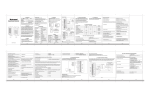
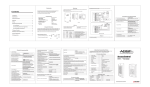
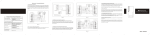
3.3 Connection Diagram
3.3.1 Common power supply
1. Introduction
Metal Waterproof Access Control
1
2
3
4
5
6
7
9
GND
D0
8
0
D1
#
ALARMOPEN
2. Technical Specifications
D_IN
Description
AC&DC
Metal case, anti-explosion and anti-tamper
AC&DC
NO
COM
NC
A C& DC
CO M
O P EN
D_IN
NO
A C& DC
D0
D1
A LA RM -
GND
D0
D1
O PEN
D_ IN
NO
NC
AC&DC
DC: 12-24V AC: 12-18V
AC&DC
Input voltage
AL A RM-
IP 65
GND
Waterproof
J1
Capacity(max)
PIN
2500
4digits Not related to the card.
Master card
Add/delete user
As reader
Support Wiegand 26bits, PIN wiegand
output is virtual number, set the facility
code, set the address of reader.
Connect external Can connect any EM/HID/IC readers with
wiegand 26 output
reader
Connect high
power alarm
External current of the alarm ≥3A
3. Installation Procedure
User Manual
3.1 Installation and Fixation
3.1.1
Drill hole on the wall according to the back size of the machine
or install distributing box well.
3.1.2
Thread the cable through cable hole, connect related cable. For
the un-used cable please separate with insulating tape and keep
well in case of short circuit.
3.1.3
Fix back cover on the wall or distributing box with screw.
3.1.4
After wiring, install front casing to the back casing and fix well.
5.4 Delete all users
Press 2 0000 #
5.5 To delete User by Manager Delete Card
Manager delete card Swipe delete user card continuously
Manager delete card That is exit delete users settings
6. Door Open mode settings
6.1 Open by cards:
Press 3 0 #
6.2 Open by cards+PIN
Press 3 1 #
Grey
Connect Alarm Negative
Yellow
Exit Button
Brown
Door Contact Button
Power
AC&DC
1 2 V /3A
Alarm Power Supply
Positive
Alarm
Red
Note: Resetting to factory default, the user's information
is still retained.
Blue
Relay NO, Normal when Circuit Open
Purple
Relay Common Port, Connect Power Supply Negative
Orange
Relay NC, Normal when Circuit Closed
Connect Power Supply Positive
S2
One door Access Control
Connect “NC” or “NO”
according to specific lock type
+
Lock
-
Diode white port connect positive side of the
lock, the other port connect the negative
PCB connect diagram
3.3.2 Special Power Supply
3.2 Wiring
Function
D0
Green
Wiegand 26 output/input
D1
White
Wiegand 26 output/input
ALARM-
Grey
Alarm Negative
OPEN
Yellow
Request to Exit Button
D_IN
Brown
Door Contact
Red
12V AC&DC Regulated Power Input
AC&DC
2.Enter into Programming Code:
Press * Master code # 888888 is the default factory
master code.
Note: Below 3 to 11 items all operation need in
programming mode.
3.Change Master Code:
Press 0 New code # New code #
Note: the master code can be any 6 digits, please
stores well.
Power
Description
Color
AC&DC
Black
12V AC&DC Regulated Power Input
NO
Blue
Relay NO
COM
Purple
Relay COM
NC
Orange
Relay NC
GND
Pink
Negative
8.2 To enable door open detection
Press 6 1 #
5.3 Synthetical Delete
Press 2 Read card1 ID number1# ... #
Wiegand Output/Input
J1
4.5 To add users by manager card
Manager add card Swipe add user card continuously
Manager add card
That is exit add users settings
5.2 Manual Delete
Press 2 ID number1# ... #
Wiegand Output/Input
White
Anti-demolition alarm
8. Door open detection settings
8.1 To disable door open detection. (Factory default)
Press 6 0 #
5. To delete users
5.1 Auto Delete
Press 2 Read card1 Read card2 ... #
Negative Output
Green
NC
4.4 To add card users synthetically
Press 1 read card1 ID number 1# read card2 ID number
2# PIN# ... #
4.6 To add consecutive card users
Press 5 ID number # 8 digits number 1 # Card number # .
Mark: The quantity of S2 cards could not exceed 2500.
The ID number must be continuous vacant number.
Pink
1.To Reset to Factory Default
To reset to factory default, power off, press “*”, hold it and
power up, release it after hearing two beeps and the LED turns
orange. The controllers is then waiting to add a new master
card. Then present any two EM cards. The first one will “add a
user card”, the second is “adding a new delete user card”. The
LED will then turn red, confirming the unit has been reset back
to factory default and new Master Cards added. If new Master
Cards are not set within 10 seconds the LED will turn in red,
and S2 goes back to working status.
Black
CO M
Features
Appearance
4. Administrator Operation
In4004
S2
This is a proximity and waterproof access controller, IP65,
which is a modern and advanced access control system. It
uses the latest central processor(CPU), S2 can store 2500
users. It supports card, card plus PIN and card/PIN three
access modes, also can add PIN independently. Anti-vandal,
alarm, exit button, safe mode, wiegand input/output, etc, which
make the user safer.
8.2.1When used with the function, ,there are two situation: if
the door is opened normally, but not closed after 1 minute, the
inside buzzer will beep automatically to remind people to close
the door and continue for 1 minute before switching off
automatically.
8.2.2if the door is forced open, the inside buzzer and alarm
output will both operate.
9. Security Mode settings
9.1 Normal status:(Factory default )
Press 7 0 #
9.2 Keypad Lockout
Press 7 1 #
If there are 10 invalid cards or 10 incorrect PIN numbers in a
10 minute period either the keypad will lockout for 10 minutes.
9.3 Alarm Output
Press 7 2 #
If there are 10 invalid cards or 10 incorrect PIN numbers in a
10 minute period either the the outside buzzer and alarm
output will both operate.
10. To set the facility code:
Press 8 1 0-255 # (Factory default is 029)
Marks:This facility PIN output as Wiegand mode: If the facility
Code is 029, PIN is 8888.When press 8888 # Facility will
output a virtual number 029,08888.
GND
D0
D1
ALARMOPEN
D_IN
AC&DC
AC&DC
NO
COM
NC
Pink
Negative Output
Green
Wiegand Output/Input
White
Wiegand Output/Input
Grey
Exit Button +
Connect
Alarm Negative
Fail-safe lock
DC12V/3A
NC
COM NO +12V GND OPEN
-
+
Fail-secure lock
Yellow
Brown
Door detecting
switch
+
Alarm“-”
Red
4.To add users
4.1 To add card users automatically.
Press 1 Read card1 Read card2 ... #
Mark: The range of ID number : 1~2500.
The ID number is auto generation and be Search continuously.
The add card will auto associate PIN “1234” (factory default) ,
this PIN could not open the door.
-
Alarm
Black
Blue
Relay NO, Normal when Circuit Open
Purple
Relay Common Port
Orange
Relay NC, Normal when Circuit Closed
S2
One door Access Control
4.2 To add card users manually
Press 1 ID number 1# read card1 ID number 2# read card2
... #
Mark: Press # means “confirm”, Press last # means end of
the current settings. Press * means to exit the current
operation
4.3 To add no-card users
Press 1 ID number 1# PIN 1 ID number 2# PIN 2 ... #
Mark: The PIN of S2 is 4 digits any number;
12. Alarm output time
Press 9 1~3 #
Factory default is 1 minute
6. Sound and Light indication
Red Light Green Light
Operation Status
Stand by
5. User Settings
1. Cards users change the PIN
* Read Card Old PIN # New PIN # Repeat New PIN #
Marks: S2 PIN is only 4digits; The PIN could not change to
“1234”
2. No card users the PIN
* ID number # Old PIN # New PIN # Repeat New PIN #
Marks: S2 PIN is only 4digits; The PIN could not change to
“1234”
五、用户操作
3. Open door by users card
Read Card If it is valid ,the door will open.
4. Open door by PIN
Users PIN # If the PIN is right, the door will open.
5. Open door by users card+PIN
Read Card Users PIN #
If the card and PIN are right, the door will open.
6. To remove the alarm
6.1 The inside buzzer and alarm output will both operate.
Read valid card or press Master Code # to reset the Door
Forced Open warning.
6.2 Close the door forced warning
Close the door or Read valid card or Master Code #
to reset the Door Forced warning
Slow flash
Off
Off
Bright
Press keypad
Buzzer
Short Ring
Operation successful
Ring...
3 Short Rings
Operation failed
Enter into
programming mode
Bright
Off
In the programming
mode
Bright
Bright
Exit from the
programming mode Slow flash
Off
Ring...
Off
Bright
Ring...
Quick flash
Off
Alarm
Open the door
Alarm
Ring...
7. Specifications
Operating Voltage
DC:12~24V
Idle Current
35±5mA
Active Current
Card Reading Distance
<80mA
Operating Temperature
-40~60℃
Lock Output Load
2A
Alarm Output Load
3A
AC:12-18V
3~6 cm
8. Packing List
Name
Machine
Packing box
Size
Quantity
S2
1 set
S2
1 piece
6.2 Open by cards or PIN(Factory default)
Press 3 2 #
11. To set the address of reader
Press 8 2 0~3 # (Factory default is 0)
Rubber bungs
¤4mm X28mm
4 PCS
Self tapping screws
¤4mm X28mm
4 PCS
7. Door relay time settings
Press 4 0~99 #
Marks: The door relay time is between 0~99 seconds, the
factory default setting is 5 seconds.
0: To set the reader address 0,wiegand output is 26bit.
1: To set the reader address 1.
2: To set the reader address 2.
3: To set the reader address 3.
Master Card
Screw driver
Drying agent
2 PCS
Star diagram
1 piece
1 Package
Remarks: Master Card (Master Add Card & Master Delete Card).