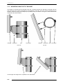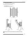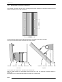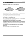
1
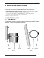
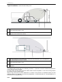
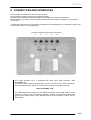
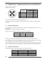
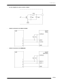
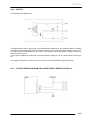
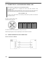
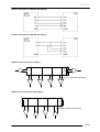
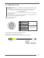
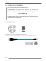
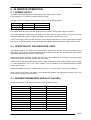
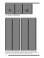
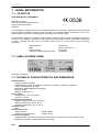
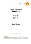
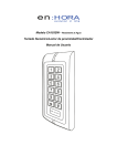
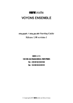
LPR3033-3034 & 3035
USER MANUAL
REFERENCE DOCUMENT: LPR303x-UM-1.4-EN
BALOGH SA
BALOGH TAG
189 Rue d’Aubervilliers - CP 97 - 75886 Paris
Cedex 18 - France
Téléphone: 33 (0)1 44 65 65 00
Fax: 33 (0)1 44 65 65 10
Web: http://www.balogh-rfid.com
3637 Old US-23
Brighton, Michigan MI 48114, USA
Tel: USA (800) 252-RFID (7343)
(810) 360-0182
Canada (800) 258-RFID (7343)
Fax: (810) 360-0237
LPR303x
Blank page
2/26
LPR303x-UM-1.4-EN
LPR303x
TABLE OF CONTENTS
FOREWORD ................................................................................... 4
1
1.1
1.2
1.3
1.4
2
PURPOSE OF THIS MANUAL ....................................................................... 4
DOCUMENT NAMING CONVENTIONS......................................................... 4
DOCUMENT STATUS SHEET ....................................................................... 4
NOTE .............................................................................................................. 4
DESCRIPTION OF READER .......................................................... 5
2.1
2.2
2.3
2.4
2.5
2.6
3
GENERAL DESCRIPTION ............................................................................. 5
WARNINGS .................................................................................................... 5
OPERATING PRINCIPLE ............................................................................... 5
COMMUNICATION INTERFACES ................................................................. 6
MODELS AVAILABLE .................................................................................... 6
OVERALL DIMENSIONS ................................................................................ 6
INSTALLING THE LPR303x READER ........................................... 7
3.1
3.2
3.3
4
MOUNTING ON A POLE ................................................................................ 7
MOUNTING ON A WALL ................................................................................ 9
POSITIONING OF READER ........................................................................ 11
CONNECTORS AND INTERFACES ............................................. 13
4.1
4.2
4.3
4.4
4.5
5
CONNECTOR N°1: POWER AND OPEN COLLECTOR INTERFACE......... 14
CONNECTOR N°2: INPUT/OUTPUT ........................................................... 16
CONNECTOR N°3: ASYNCHRONOUS SERIAL LINK................................. 18
CONNECTOR N°4: USB .............................................................................. 21
CONNECTOR N°5: ETHERNET................................................................... 22
IN SERVICE OPERATION ............................................................ 23
5.1
5.2
5.3
5.4
6
POWER SUPPLY ......................................................................................... 23
OPERATION OF THE INDICATOR LIGHT .................................................. 23
READER PARAMETERS (DEFAULT VALUES)........................................... 23
CHANNEL FREQUENCIES .......................................................................... 24
MAINTENANCE ............................................................................ 25
6.1
6.2
6.3
7
PERIODIC MAINTENANCE ......................................................................... 25
REPLACEMENT ........................................................................................... 25
RECYCLING ................................................................................................. 25
LEGAL INFORMATION................................................................. 26
7.1
7.2
7.3
CE NOTICE .................................................................................................. 26
LABEL ON REAR PANEL ............................................................................. 26
TECHNICAL CHARACTERISTICS AND DIMENSIONS............................... 26
3/26
LPR303x-UM-1.4-EN
LPR303x
1 FOREWORD
1.1 PURPOSE OF THIS MANUAL
This manual presents the BALOGH HYPER X readers LPR3033- LPR 3034 and LPR 3035.
In this manual these readers are named LPR303x
It describes how to install and how to use it.
Further information pertaining to the data interfaces described in this manual can be found in the
Interface Manual (reference LPR303x-IM-x.y-EN).
1.2 DOCUMENT NAMING CONVENTIONS
The coding used for a manual name is:
<device name>- UM-II-L
in which:
UM signifies User Manual
II refers to the issue or version number
L refers to the language of the manual
1.3 DOCUMENT STATUS SHEET
Version
1.0
1.1 and 1.2
Date
02/06/2012
1.3
14/06/2012
1.4
30/8/2013
Description of changes
Creation (translation of French version 1.2)
unused
Minor and topographic corrections
Synchronization with French version 1.3
Introduction of LPR 3033 - 3035
1.4 NOTE
The contents of this manual are subject to changes without notice.
BALOGH cannot be held responsible for the consequences of any error, omission, or incorrect
interpretation of the information provided.
4/26
LPR303x-UM-1.4-EN
LPR303x
2 DESCRIPTION OF READER
2.1 GENERAL DESCRIPTION
LPR303x readers will identify HyperX™ tags on the fly at distances of up to 4m for LPR3033, up to 6m for
LPR3034 and up to 10m for LPR3035.
Reader
distance up to
LPR3033
4m
LPR3034
6m
LPR3035
10m
The reader is a compact all-in-one device. The weatherproof housing of sober design contains all the
functional elements of the reading unit: Antennas, Microwave generator, receiver, CPU and
communication interface.
The reader can be mounted directly onto any panel, even a metallic one. An optional tilt and swivel mount
allows installation on both poles and flat surfaces. In this way the antenna can be appropriately pointed to
the zone where the tags need to be identified.
The main characteristics are as follows:
•
•
•
•
•
•
•
Case dimensions: 276x186x30mm
Overall dimensions: 276x186x57mm
Weight: 2.5 kg
Cover color: Grey RAL 7035
IP65 protection
Power requirements: between +12Vdc and +24Vdc, max current 1.5A.
Operating temperature: -20°C to +50°C
2.2 WARNINGS
Tags may be damaged or deprogrammed if used in the immediate vicinity of GSM mobile phones. A
safety distance of at least 10 cm must be maintained between the tags and the mobile phones.
Installation of long-range readers must only be done in zones where the technical and environmental
conditions comply with those specified by the manufacturer.
BALOGH cannot be held responsible for any damages caused by an incorrect installation.
Any changes made to the device will immediately nullify the warranty.
2.3 OPERATING PRINCIPLE
Electromagnetic radiation in the frequency range 1 to 100 GHz is called microwaves.
Their physical characteristics allow high data rates and good directivity. Reading antennas are smaller
and performance is relatively independent of the environment.
Tags are not active when not in the reader's antenna zone.
The tag's originality (patented) is its capacity to reflect the microwaves emitted by the readers. A tag
receiving an incident unmodulated 2.45 GHz carrier, will reflect this wave but modulated by its own
identification code.
The reader receives and processes this signal and then converts and sends the data to a host system
over a standardized connection.
5/26
LPR303x-UM-1.4-EN
LPR303x
2.4 COMMUNICATION INTERFACES
These readers can be used in place of most conventional controllers, both contact and contact-less.
Communication with a "host" system takes place using the following standardized links:
: • Open-collector:
DATA/CLOCK, WIEGAND 26bits
• Serial asynchronous:
RS232, RS422 or RS485
ETHERNET
USB (also used for maintenance).
For the USB, RS and ETHERNET links, full two-way communication is possible using the MODBUS™
protocol.
For some versions, all the interfaces are not available simultaneously.
These readers are also equipped with:
• An opto-coupled digital output that can be configured to switch either via a command sent from the
host or automatically at each tag identification.
• An opto-coupled digital input which can be used to globally enable or disable tag reading.
The readers must be powered with 12 - 24 VDC. A special detector ensures that if the input voltage is too
low then the reader will not power up. Powering the reader from a mains outlet requires an AC adaptor of
at least 18W.
2.5 MODELS AVAILABLE
• LPR303x TTL
Wiegand 26 bits and DATA/CLOCK
USB for maintenance
• LPR303x ETH
Wiegand 26 bits and DATA/CLOCK
RS 232, RS 422, RS 485
ETHERNET
USB (also used for maintenance).
2.6 OVERALL DIMENSIONS
6/26
LPR303x-UM-1.4-EN
LPR303x
3 INSTALLING THE LPR303x READER
At the rear of the reader are two mounting brackets.
These brackets have self-clinching nuts size M6 allowing mounting on any support structure (e.g. support
angles with screws)
These brackets also have oblong holes allowing plastic or metallic collars to pass through.
A mounting kit allowing easy installation of the reader is available as an accessory. This kit contains:
- a tilt bracket which allows adjusting the tilt angle
- a wall-mounting support which allows adjustment of horizontal rotation
- 2 metallic hose clamps Ø30mm for attaching the tilt mount onto the support structure
- 4 mounting screws for attaching the reader onto the tilt bracket
All the pieces are made of stainless steel.
3.1 MOUNTING ON A POLE
3.1.1
DIRECT MOUNTING
The reader can be mounted directly onto a pole by with a hose clamp that passes through the openings in
the brackets. This type of mount only allows horizontal rotation:
LPR303x
pole
side view
hose clamp
LPR303x
pole
hose clamp
top view
7/26
LPR303x-UM-1.4-EN
LPR303x
3.1.2
MOUNTING USING THE TILT BRACKET
The reader is mounted onto the bracket using the 4 screws provided, the bracket is mounted onto the
pole using the hose clamps. Depending on the diameter of the pole, the hose clamps provided may be
suitable, otherwise larger hose clamps (not provided) may be needed. This type of mount allows both
horizontal and vertical rotation.
LPR303x
tilt bracket
pole
hose clamp
side view
LPR303x
tilt bracket
pole hose clamp
top view
The tilt angle can range from 5° upwards to 45° downwards
8/26
LPR303x-UM-1.4-EN
LPR303x
3.2 MOUNTING ON A WALL
3.2.1
MOUNTING USING THE TILT BRACKET
The tilt bracket has 4 holes for wall mounting.
-
4 screws Ø6mm max
screw type must be chosen to suit wall material
40mm between axes in both directions
LPR303x
tilt bracket
side view
wall
LPR303x
tilt bracket
wall
top view
This type of mount only allows a vertical tilt adjustment from 5° upwards to 45° downwards.
Note: by rotating the bracket 90° (wings are horizontal), horizontal rotation becomes possible.
9/26
LPR303x-UM-1.4-EN
LPR303x
3.2.2
MOUNTING WITH WALL BRACKET
This bracket, provided in the kit, has 4 mounting holes, whose locations are identical to those of the tilt
bracket. Mounting onto the wall is identical:
The tilt bracket is attached to the wall bracket with the 2 metallic hose clamps provided.
This type of mount allows both horizontal and vertical rotation:
LPR303x
tilt bracket
hose clamp
side view
wall bracket
wall
LPR303x
tilt bracket wall bracket
wall
top view
The tilt angle can range from 5° upwards to 45° downwards.
With the reader pointing 45° downwards and mounted on a wall, the maximum horizontal rotation is
roughly 30°.
When there is no tilt, the horizontal rotation can reach 50° on either side.
10/26
LPR303x-UM-1.4-EN
LPR303x
3.3 POSITIONING OF READER
The directivity of the reader's antenna is a symmetrical 45° x 45°.
Mounting the reader horizontally or vertically does not affect its performance.
Side view
Top view
y
z
45°
45°
y
z
Position the reader so that it points to the zone where the tags are likely to be. Maximum performance is
always achieved with the line of sight perpendicular to the face of the reader.
With the mounting elements provided, the reader can now be pivoted. The orientation can be freely
adjusted. Pivoting can be either horizontal (side to side) or vertical (up and down).
When positioning the reader, the following recommendations should be followed:
Avoid placing the reader in direct sunlight, where overheating may cause the internal electronics to reach
temperatures above those recommended for normal operation.
If this is not possible then a sun-shield should be mounted.
When two or more readers are situated in the same zone, make sure they are not pointing towards each
other.
If necessary, their pointing axes should be slightly redirected.
The frequency channels should be as far apart as possible. A separation of 0.750 MHz is recommended
for readers situated close together (see the frequency table at the end of the manual).
Do not install a reader close to a source of potential interference in order not to degrade its performance.
The indicated reading distance is a nominal value and the actual range is usually greater. However there
are several sources of interference present in the environment which may affect reader performance and
which must be taken into account. Quite often this interference cannot be removed and results in a
reduced reading range.
The main sources of interference are:
Devices operating in the same band of frequencies, such as wireless communications (WLAN),
Mobile phones and smartphones,
Microwave ovens,
Fluorescent lighting,
Metal objects such as gratings, fences or heat-reflective vehicle windscreens,
Etc.
11/26
LPR303x-UM-1.4-EN
LPR303x
Typical installation: Inclined frontal reading zone
1
Theoretical identification zone
2
Reader. The reader should be positioned so that the angle is between about 30 and 45
degrees down towards the vehicle.
1
The tag, fastened on the windscreen, should be inclined between 30 to 45 degrees for
an optimal alignment with the reader.
2
Theoretical identification zone
3
Reader. The reader should be positioned so that the angle is between about 30 and 45
degrees.
The diagram above shows the best reader/tag orientation. In particular it avoids unwanted identifications
in front of but far from the reader.
For best results, the tag surface and the reader surface should be parallel. In this case, the tag reflects
the maximum of the received signal.
When a tag is fixed to the vehicle windscreen, be aware of the presence of metalized areas (for heat
reflection) which can degrade or prevent tag identification. Contact BALOGH for recommendations on
best practices for tag positioning.
12/26
LPR303x-UM-1.4-EN
LPR303x
4 CONNECTORS AND INTERFACES
All the reader's connectors are found on the rear panel.
All connectors are panel mounts using the M12 standard.
Moulded cable assemblies of different lengths are available from several manufacturers.
Manual assembly of cable connectors allows choosing between soldered, crimped or screw-terminal
connections.
ATTENTION: these M12 type connectors are designed for hand-tightening only. Spanners or pliers must
not be used in order not to cause damage.
Connector numbers (rear view of LPR-303x)
1
2
3
4
5
The model LPR303x ETH, is equipped with three serial data interfaces: USB,
ETHERNET, RS.
These three cannot operate simultaneously, only one at a time can be used. Selection is
done automatically when cables are connected, according to the following priority:
USB > ETHERNET > RS
The USB interface has priority over the Ethernet interface, so the USB cable must be
removed in order to use the Ethernet interface. Similarly, the Ethernet interface has
priority over the RS interface, so the Ethernet cable must be removed in order to use the
RS interface.
13/26
LPR303x-UM-1.4-EN
LPR303x
4.1 CONNECTOR N°1: POWER AND OPEN COLLECTOR INTERFACE
M12 plug, A-coding, male, 5 pins.
Connector pinout, front view:
POWER
1
2
3
4
5
Open Collector
DATA/CLOCK WIEGAND
+DC
DATA
DATA “0”
CLOCK
DATA “1”
GND
GND
0V
The cable connector must be type M12 A-coding, female, 5 pins.
This connector has 2 functions: reader power supply and open collector interface for DATA/CLOCK and
WIEGAND
4.1.1
READER POWER SUPPLY
The reader requires a DC power supply of between 12Vdc and 24Vdc applied between pins 1 and 4 of
the connector.
Current drawn is 1.5 A maximum during power-up surge.
Average currents for steady-state operation are given in the following table:
Input Voltage
TTL Model
RS-ETH Model
12V
550mA
600mA
24V
350mA
400mA
The reader electronics are protected against polarity inversion for the power supply connection.
Pay careful attention to the length and gauge of the wire used. As ohmic losses in the power lead can
cause a voltage drop, make sure the input voltage to the reader is greater than 11.5V.
If the power supply cannot provide sufficient current during the power-up, the front-panel light will blink
red. This is not a fault condition, but an indication that a better-dimensioned power supply must be used..
4.1.2
OPEN-COLLECTOR LINK:
Different signals appear on the pins depending on which interface is selected.
pin
1
2
3
4
5
DATA/CLOCK
WIEGAND
DATA
CLOCK
DATA “0”
DATA “1”
GND
GND
14/26
LPR303x-UM-1.4-EN
LPR303x
-
Circuit diagram for open collector output:
-
reader connections for DATA-CLOCK:
-
reader connections for WIEGAND
15/26
LPR303x-UM-1.4-EN
LPR303x
4.2 CONNECTOR N°2: INPUT/OUTPUT
M12 plug, A-coding, female, 5 pins.
Connector pinout, front view:
1 E+
2 E–
INPUT
3 SV
4 S+
OUTPUT
5 S–
The cable connector must be type M12 A-coding, male, 5 pins.
A 4-pin connector can be used if the output is not used.
4.2.1
INPUT
Circuit diagram for digital input:
The digital input uses an optocoupler to provide galvanic isolation from the reader electronics. An open
circuit or a positive voltage less than 4.4V applied to the pin E+ will produce the internal logic state "1", a
voltage between 7.1V and 24V will produce the state "0". This input is sampled and the state updated
every 50ms. If the applied voltage is greater than 7.1V, the bit E1 of the status word is reset to 0. During
normal operation, the applied voltage should not be above 24V.
This input allows enabling or disabling tag reading, e.g. when a loop vehicle detector provides a control
signal.
16/26
LPR303x-UM-1.4-EN
LPR303x
4.2.2
OUTPUT
Circuit diagram for digital output::
The digital output uses an optocoupler to provide galvanic isolation from the reader electronics. Enabling
the output turns the output transistor and current is drawn from an external voltage applied on the SV pin.
The load is connected between pins S+ and SV. The collector current will induce a voltage of about 1V
between these two pins.
If the output is disabled, the transistor is turned off and the voltage on pin S+ will be equal to that on pin
SV.
This output is designed to control a 12V or 24V relay. The current available is typically 100mA.
4.2.3
TYPICAL WIRING DIAGRAM FOR CONNECTING A BUZZER OR RELAY:
17/26
LPR303x-UM-1.4-EN
LPR303x
4.3 CONNECTOR N°3: ASYNCHRONOUS SERIAL LINK
This connector is only present in the LPR303x ETH model
The model LPR303x ETH is equipped with three serial data interfaces: USB,
ETHERNET, RS.
These three cannot operate simultaneously, only one at a time can be used. Selection is
done automatically when cables are connected, according to the following priority:
USB > ETHERNET > RS
In order to use the RS interface it is necessary to disconnect any cables on the Ethernet
and USB connectors.
M12 plug, A-coding, female, 5 pins.
Connector pinout, front view:
pin
1
2
3
4
5
RS-232
TX
—
—
RX
GND
RS-422
TX+
TX–
RX+
RX–
GND
RS-485
V1+
V1–
V2+
V2–
GND
The cable connector must be type M12 A-coding, male, 5 pins.
Different signals appear on the pins depending on which interface is selected.
4.3.1
WIRING DIAGRAMS FOR HOST CONNECTIONS
Reader connections for RS-232:
18/26
LPR303x-UM-1.4-EN
LPR303x
Reader connections for RS-422 (full-duplex):
Reader connections for RS-485 (full-duplex):
Network connections (bus, simplex).
R
R must be connected if necessary
Network connections (bus, half-duplex).
R
R
R must be connected if necessary
19/26
LPR303x-UM-1.4-EN
LPR303x
4.3.2
ELECTRICAL CONNECTIONS
Cables to use for RS-422 and RS-485 links
• In the absence of electrical noise - unshielded twisted pairs.
• In a noisy environment - individually shielded twisted pairs
Cables are characterized by:
- their characteristic impedance (Z0 in ohms)
- their distributed capacity (CL in pF/m).
- their distributed resistance (RL in ohms/m)
For short cable lengths, normal cables are satisfactory.
For cables longer than 1000 m, high quality cables (low CL and RL) should be used for all baud rates.
Signal inversions
For an RS-232 link, signal polarities and levels are well defined. On both devices RX is connected to TX
and vice-versa.
For an RS-422 or RS-485 link, the signal “+” is normally at a high level at rest and active low, the reverse
is true for the signal "–". This is the case for this reader. If however the differential signals are generated
by a converter from an RS-232 interface, then the “+” line can be at a low level at rest and active high. In
this case, the signals must be inverted.
Half-duplex interface
In the case of an RS-485 “2-wire” (half-duplex) link, the signals V1+ and V2+ must be connected together
and connected to the V+ pin on the host device. Similarly, the signals V1– and V2– must be connected
together and connected to the V– pin on the host device.
Connection of GND
For an RS-232 link, the GND of each equipment must be at the same potential. Consequently, the signal
GND (pin 5 on connector) must be connected to the chassis of the host equipment. For a differential link,
this GND connection is not absolutely necessary but often recommended.
Line termination
For baud rates not greater than 1200bps, no termination is necessary. For baud rates greater than
9600bps and line lengths greater than a few hundred meters, a resistor equal to the line impedance (≈120
ohms) is essential.
For a simplex link (one-way), the termination (if present) should be placed at the receiving end..
For a duplex link (two-way), the termination (if present) should be placed at each end of the line.
Line biasing
For RS-422 and RS-485 links, biasing may be necessary. This is done externally and only at one point on
the line.
The line “+” is connected to +5V via a 4.7K resistor.
The line “–” is connected to GND via a 4.7K resistor.
20/26
LPR303x-UM-1.4-EN
LPR303x
4.4 CONNECTOR N°4: USB
The model LPR303x ETH is equipped with three serial data interfaces: USB,
ETHERNET, RS.
These three cannot operate simultaneously, only one at a time can be used. Selection is
done automatically when cables are connected, according to the following priority:
USB > ETHERNET > RS
In order to use the RS interface it is necessary to disconnect any cables on the ethernet
and USB connectors.
The USB interface has priority over the other interfaces, so the USB cable must be
removed in order to use the ethernet or RS interfaces.
M12 plug, A-coding, female, 8 pins.
Connector pinout, front view:
1
2
3
4
5
6
7
8
VUSB (+5V)
DATADATA+
CHASSIS
do not connect
do not connect
do not connect
do not connect
USB
RESERVED (TEST)
The cable connector must be type M12 A-coding, male, 8 pins.
We recommend using a cable less than 2m in length.
A suitable cable for connecting the reader to a PC is available as an accessory:
21/26
LPR303x-UM-1.4-EN
LPR303x
4.5 CONNECTOR N°5: ETHERNET
This connector is only present in the LPR303x ETH model
The model LPR303x ETH is equipped with three serial data interfaces: USB,
ETHERNET, RS.
These three cannot operate simultaneously, only one at a time can be used. Selection is
done automatically when cables are connected, according to the following priority:
USB > ETHERNET > RS
In order to use the Ethernet interface it is necessary to disconnect the USB cable.
The Ethernet interface has priority over the RS interface, so the Ethernet cable must be
removed in order to use the RS interface
M12 plug, D-coding, female, 4 pins.
Connector pinout, front view:
1
2
3
4
T+
R+
T–
R–
The cable connector must be type M12 D-coding, male, 4 pins.
A suitable cable for connecting the reader to an Ethernet device is available as an accessory:
22/26
LPR303x-UM-1.4-EN
LPR303x
5 IN SERVICE OPERATION
5.1 POWER SUPPLY
The reader must be powered from a DC supply in the range 12Vdc - 24Vdc.
Current drawn is 1.5 A maximum during power-up surge.
Average currents for steady-state operation are given in the following table:
Input Voltage
12V
24V
TTL Model
550mA
350mA
RS-ETH Model
600mA
400mA
The reader electronics are protected against polarity inversion for the power supply connection.
Pay careful attention to the length and gauge of the wire used. As ohmic losses in the power lead can
cause a voltage drop, make sure the input voltage to the reader is greater than 11.5V.
If the power supply cannot provide sufficient current during the power-up, the front-panel light will blink
red. This is not a fault condition, but an indication that a better-dimensioned power supply must be used..
5.2 OPERATION OF THE INDICATOR LIGHT
The indicator light on the reader conveys the reader's behaviour to the user. It is the only visible part of
the system. It is controlled by the embedded reader software. It can also be put under host control using
appropriate MODBUS commands via a serial link.
During the initialization phase, the light is a fixed red. If the initialization is successful, the indicator light
starts to flash green, otherwise it flashes red very slowly.
If after power-on the light flashes quickly, this is usually caused by a power supply problem, either voltage
or current insufficient. This is not a fault condition, but an indication that a better-dimensioned power
supply must be used..
During the reading of a tag, the indicator light goes out for one second, then resumes green flashing.
When reading a tag with a low battery, the indicator light flashes red briefly before going out for one
second, then it resumes green flashing.
5.3 READER PARAMETERS (DEFAULT VALUES)
All of the parameters in the table are saved in the non-volatile memory.
Parameter
Default value
Configuration
Channel N°
Persistence
Issuer code filtering
Issuer code size
Indicator light
Message mode
RS interface type
Open collector interface
MODBUS address
Data rate
Character format
0
2
0
3
0
0
0
0
1
0
0
Frequency hopping
1s
no filtering
3 characters
NORMAL
Type 0
RS232
not used
Address 1
9600 bps
8 bits no parity
23/26
LPR303x-UM-1.4-EN
LPR303x
Parameter
Default value
Configuration
Frame type
Polling / Interrupt
MTBM
Nb Emissions
Output
Range
Input
Channel hopping period
Test serial interface
0
0
2
1
2
3
0
3
0
ASCII
Interrupt
0.5s
1 emission in interrupt mode
ident 2s
max range
disabled
300ms
disabled
5.4 CHANNEL FREQUENCIES
Sorted by frequency
Frequency (MHz)
Channel number
2446.25
31
2446.50
24
2446.75
25
2447.00
26
2447.25
27
2447.50
28
2447.75
29
2448.00
1
2448.25
2
2448.50
3
2448.75
4
2449.00
5
2449.25
6
2449.50
7
2449.75.
8
2450.00
9
2450.25
10
2450.50
11
2450.75
12
2451.00
13
2451.25
14
2451.50
15
2451.75
16
2452.00
17
2452.25
18
2452.50
19
2452.75
20
2453.00
21
2453.25
22
2453.50
23
2453.75
30
Sorted by channel number
Channel number
Frequency (MHz)
1
2448.00
2
2448.25
3
2448.50
4
2448.75
5
2449.00
6
2449.25
7
2449.50
8
2449.75.
9
2450.00
10
2450.25
11
2450.50
12
2450.75
13
2451.00
14
2451.25
15
2451.50
16
2451.75
17
2452.00
18
2452.25
19
2452.50
20
2452.75
21
2453.00
22
2453.25
23
2453.50
24
2446.50
25
2446.75
26
2447.00
27
2447.25
28
2447.50
29
2447.75
30
2453.75
31
2446.25
Channel number 0 is used for the frequency hopping mode. In this mode, the reader operates for a
certain time on one channel, then hops onto another channel, and so on. The sequence is pseudorandom and the time the reader spends on any particular channel is determined by the "Hopping period"
parameter. The frequencies/channels used cover all of the available frequency band.
24/26
LPR303x-UM-1.4-EN
LPR303x
6 MAINTENANCE
6.1 PERIODIC MAINTENANCE
The LPR303x reader requires no periodic maintenance
The reader should be regularly cleaned in order to avoid dust and dirt accumulating on the case.
The reader should be regularly checked for:
cracks in the case
missing mounting screws
screws correctly tightened
connectors correctly locked
6.2 REPLACEMENT
If the LPR303x needs to be replaced, the procedure is as follows:
-
Turn the knurled ring of the plugs anti-clockwise to unlock the connectors.
Record the reader orientation (azimuth and elevation), then remove the mounting screws and
dismount the unit.
Place the new unit in the same position, insert the mounting screws and tighten correctly.
Replace connectors and for each turn the knurled ring clockwise until locked.
ATTENTION: these M12 type connectors are designed for hand-tightening only. Spanners or pliers must
not be used in order not to cause damage.
6.3 RECYCLING
All decommissioned readers must be returned to BALOGH SA for appropriate recycling according to
directive D3E.
25/26
LPR303x-UM-1.4-EN
LPR303x
7 LEGAL INFORMATION
7.1 CE NOTICE
DECLARATION OF CONFORMITY
BALOGH Toulouse
105 Avenue du Général Eisenhower
31023 TOULOUSE cedex 1
FRANCE
0536
This declaration certifies that the device LPR303x satisfies the essential requirements of the European
directive R&TTE 1999/5/EC aiming to align the laws of the Member States relating to the use of the
electromagnetic spectrum, electromagnetic compatibility and electrical safety.
This declaration applies to all readers manufactured according to the technical specifications outlined in
Annexe II of the directive. Evaluation of the conformity of the equipment with the essential requirements
of article 3 R&TTE has been done in accordance with Annex IV of the directive and the following
standards:
Radio spectrum:
EMC:
Electrical safety:
Exposure to electromagnetic fields:
EN 300 440
EN 301 489-1 and -3
EN 60 950
EN 50 364
7.2 LABEL ON REAR PANEL
Example for LPR3034
7.3 TECHNICAL CHARACTERISTICS AND DIMENSIONS
Radio frequency
• Frequency band: 2.45 GHz
• Radiated power: 75mW for LPR3033 - 200mW for LPR3034 – 350mW for LPR3035
• Tag to reader data rate: 30 Kbps
• Modulation: BPSK (Biphase Shift Keying)
• Protocol: HDLC
• Number of channels: 31
Power supply
• Voltage range: 12 to 24 Volts DC
• Current: 1.5A max
Environmental conditions
• Relative humidity: 90% non-condensing
• Storage temperature: -25° to +80° C
• Operating temperature: -20° to +50° C
Protection class
• IP65
External dimensions
• Length: 276mm
• Width: 186mm
• Thickness: 30mm/56.5mm
• Weight: 2.5 kg
Connections available
• Wiegand 26bits, DATA/CLOCK (magnetic stripe ISO 7811-2), RS 232, RS 422, RS485, USB,
ETHERNET (interfaces available depending on model)
26/26
LPR303x-UM-1.4-EN