1
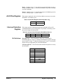
Contents
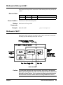
HP E2270A, E2271A, E2272A User’s and SCPI Programming Manual
Edition 1
Warranty ....................................................................................................................... 5
Safety Symbols ............................................................................................................. 6
WARNINGS ................................................................................................................. 6
WARNINGS ................................................................................................................. 7
Declaration of Conformity............................................................................................ 8
Reader Comment Sheet ................................................................................................ 9
Chapter 1
Getting Started ............................................................................................................. 11
What’s in this Manual? ............................................................................................... 11
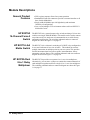
Module Descriptions................................................................................................... 12
General Product Features .................................................................................... 12
HP E2270A 16-Channel Form A Switch ............................................................ 12
HP E2271A 4x4 Matrix Switch .......................................................................... 12
HP E2272A Dual 8-to-1 Relay Multiplexer ........................................................ 12
Wiring and Configuration ........................................................................................... 13
Identfying M-Modules ........................................................................................ 13
Assembling the Field Wiring Connector ............................................................ 14
HP E2270A Form A Switch Wiring Information ............................................... 15
HP E2271A 4x4 Matrix Switch Wiring Information .......................................... 16
HP E2272A Dual 8-to-1 Relay Multiplexer Wiring Information ....................... 17
Setting HP E2272A Multiplexer Size ................................................................. 18
Chapter 2
SCPI Programming ..................................................................................................... 19
Using This Chapter ..................................................................................................... 19
Example1: Initial Operation........................................................................................ 19
Closing and Opening Channels................................................................................... 21
Channel Lists ....................................................................................................... 21
Example 2: Closing Multiple Channels ...................................................................... 22
Chapter 3
SCPI Command Reference ......................................................................................... 25
DIAGnostic Subsystem............................................................................................... 28
DIAGnostic:INTerrupt:LINE <intr_line> ........................................................... 28
DIAGnostic:INTerrupt:LINE? ............................................................................ 29
DIAGnostic:TEST? ............................................................................................. 29
DISPlay Subsystem..................................................................................................... 31
DISPlay:MONitor:[STATe] <boolean> .............................................................. 31
DISPlay:MONitor:[STATe]? .............................................................................. 32
[ROUTe] Subsystem................................................................................................... 33
[ROUTe]:CLOSe <channel list> ......................................................................... 33
[ROUTe]:CLOSe? <channel list> ....................................................................... 35
[ROUTe]:OPEN <channel list> .......................................................................... 36
[ROUTe]:OPEN? <channel list> ........................................................................ 38
STATus Subsystem..................................................................................................... 40
SYSTem Subsystem ................................................................................................... 41
Contents
1
SYSTem:ERRor? ................................................................................................ 41
SYSTem:VERSion? ............................................................................................ 42
IEEE Common Commands......................................................................................... 43
*CLS .................................................................................................................... 43
*ESE <mask> ...................................................................................................... 43
*ESE? .................................................................................................................. 44
*ESR? .................................................................................................................. 46
*IDN? .................................................................................................................. 47
*OPC ................................................................................................................... 47
*OPC? ................................................................................................................. 47
*RCL <state> ...................................................................................................... 48
*RST .................................................................................................................... 48
*SAV <state> ...................................................................................................... 49
*SRE <mask> ...................................................................................................... 49
*SRE? .................................................................................................................. 50
*STB? .................................................................................................................. 51
*TST? .................................................................................................................. 52
*WAI ................................................................................................................... 52
SCPI Command Quick Reference .............................................................................. 53
Common Command Quick Reference ........................................................................ 54
Chapter 4
Register Programming ................................................................................................ 55
Introduction................................................................................................................. 55
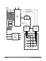
Block Diagram Description ........................................................................................ 55
Module Control ................................................................................................... 55
ID EEPROM ....................................................................................................... 56
Row and Column Drivers .................................................................................... 56
Driver Power Switch ........................................................................................... 56
Relay Coils .......................................................................................................... 56
Reset and Power Conditioning ............................................................................ 56
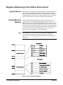
Register Addressing in the VXIbus Environment ...................................................... 58
Logical Address ................................................................................................... 58
A16/A24 Memory Mapping ............................................................................... 58
Determining a Module’s A16 Base Address ....................................................... 59
Addressing A16 Registers ................................................................................... 60
Addressing A24 Registers ................................................................................... 60
Program Example ....................................................................................................... 61
Switch M-Module A16 Register Descriptions............................................................ 63
VXI ID Register .................................................................................................. 63
VXI Device Type Register .................................................................................. 63
VXI Status/Control Register ............................................................................... 64
A24 Offset Register ............................................................................................. 65
Interrupt Selection Register ................................................................................. 65
Switch M-Module A24 Register Descriptions............................................................ 66
Status Register ..................................................................................................... 67
Control Register .................................................................................................. 68
Reserved Registers .............................................................................................. 69
2
Contents
Row Set and Reset Registers ............................................................................... 69
Matrix Drive to Channel Mappings .................................................................... 71
Unused Registers ................................................................................................. 72
ID EEPROM Register ......................................................................................... 72
Appendix A
Specifications ................................................................................................................ 75
M-Module Specification Compliance......................................................................... 75
HP E2270A 16-Channel Form A Switch Specifications ............................................ 75
HP E2271A 4x4 Matrix Switch Specifications .......................................................... 77
HP E2272A Dual 8-to-1 Relay Multiplexer Specifications........................................ 79
Index ................................................................................................................................ 81
Contents
3
4
Contents
Certification
Hewlett-Packard Company certifies that this product met its published specifications at the time of shipment from the factory. HewlettPackard further certifies that its calibration measurements are traceable to the United States National Institute of Standards and
Technology (formerly National Bureau of Standards), to the extent allowed by that organization’s calibration facility, and to the
calibration facilities of other International Standards Organization members.
Warranty
This Hewlett-Packard product is warranted against defects in materials and workmanship for a period of three years from date of shipment.
Duration and conditions of warranty for this product may be superseded when the product is integrated into (becomes a part of) other HP
products. During the warranty period, Hewlett-Packard Company will, at its option, either repair or replace products which prove to be
defective.
For warranty service or repair, this product must be returned to a service facility designated by Hewlett-Packard (HP). Buyer shall prepay
shipping charges to HP and HP shall pay shipping charges to return the product to Buyer. However, Buyer shall pay all shipping charges,
duties, and taxes for products returned to HP from another country
HP warrants that its software and firmware designated by HP for use with a product will execute its programming instructions when
properly installed on that product. HP does not warrant that the operation of the product, or software, or firmware will be uninterrupted
or error free.
Limitation Of Warranty
The foregoing warranty shall not apply to defects resulting from improper or inadequate maintenance by Buyer, Buyer-supplied pr oducts
or interfacing, unauthorized modification or misuse, operation outside of the environmental specifications for the product, or improper
site preparation or maintenance.
The design and implementation of any circuit on this product is the sole responsibility of the Buyer. HP does not warrant the Buyer’s
circuitry or malfunctions of HP products that result from the Buyer’s circuitry. In addition, HP does not warrant any damage that occurs
as a result of the Buyer’s circuit or any defects that result from Buyer-supplied products.
NO OTHER WARRANTY IS EXPRESSED OR IMPLIED. HP SPECIFICALLY DISCLAIMS THE IMPLIED WARRANTIES OF
MERCHANTABILITY AND FITNESS FOR A PARTICULAR PURPOSE.
Exclusive Remedies
THE REMEDIES PROVIDED HEREIN ARE BUYER’S SOLE AND EXCLUSIVE REMEDIES. HP SHALL NOT BE LIABLE FOR
ANY DIRECT, INDIRECT, SPECIAL, INCIDENTAL, OR CONSEQUENTIAL DAMAGES, WHETHER BASED ON CONTRACT,
TORT, OR ANY OTHER LEGAL THEORY.
Notice
The information contained in this document is subject to change without notice. HEWLETT-PACKARD (HP) MAKES NO
WARRANTY OF ANY KIND WITH REGARD TO THIS MATERIAL, INCLUDING, BUT NOT LIMITED TO, THE IMPLIED
WARRANTIES OF MERCHANTABILITY AND FITNESS FOR A PARTICULAR PURPOSE. HP shall not be liable for errors
contained herein or for incidental or consequential damages in connection with the furnishing, performance or use of this material. This
document contains proprietary information which is protected by copyright. All rights are reserved. No part of this document may be
photocopied, reproduced, or translated to another language without the prior written consent of Hewlett-Packard Company. HP assumes
no responsibility for the use or reliability of its software on equipment that is not furnished by HP.
U.S. Government Restricted Rights
The Software and Documentation have been developed entirely at private expense. They are delivered and licensed as "commercial
computer software" as defined in DFARS 252.227- 7013 (Oct 1988), DFARS 252.211-7015 (May 1991) or DFARS 252.227-7014 (Jun
1995), as a "commercial item" as defined in FAR 2.101(a), or as "Restricted computer software" as defined in FAR 52.227-19 (Jun
1987)(or any equivalent agency regulation or contract clause), whichever is applicable. You have only those rights provided for such
Software and Documentation by the applicable FAR or DFARS clause or the HP standard software agreement for the product involved
HP E2270A, E2271A, E2272A User’s and SCPI Programming Manual
Edition 1
Copyright © 1997 Hewlett-Packard Company. All Rights Reserved.
5
Documentation History
All Editions and Updates of this manual and their creation date are listed below. The first Edition of the manual is Edition 1. The Edition
number increments by 1 whenever the manual is revised. Updates, which are issued between Editions, contain replacement pages to
correct or add additional information to the current Edition of the manual. Whenever a new Edition is created, it will contain all of the
Update information for the previous Edition. Each new Edition or Update also includes a revised copy of this documentation hist ory page.
Edition 1 . . . . . . . . . . . . . . . . . . . . . . . . . . . . . . . . . . . . . . . . . . . . . . . .June 1997
Safety Symbols
Instruction manual symbol affixed to
product. Indicates that the user must refer to
the manual for specific WARNING or
CAUTION information to avoid personal
injury or damage to the product.
Alternating current (AC)
Direct current (DC).
Indicates hazardous voltages.
Indicates the field wiring terminal that must
be connected to earth ground before
operating the equipment—protects against
electrical shock in case of fault.
or
Frame or chassis ground terminal—typically
connects to the equipment's metal frame.
Calls attention to a procedure, practice, or
WARNING condition that could cause bodily injury or
death.
Calls attention to a procedure, practice, or
CAUTION condition that could possibly cause damage to
equipment or permanent loss of data.
WARNINGS
The following general safety precautions must be observed during all phases of operation, service, and repair of this product. Failure to
comply with these precautions or with specific warnings elsewhere in this manual violates safety standards of design, manufacture, and
intended use of the product. Hewlett-Packard Company assumes no liability for the customer's failure to comply with these requirements.
Ground the equipment: For Safety Class 1 equipment (equipment having a protective earth terminal), an uninterruptible safety earth
ground must be provided from the mains power source to the product input wiring terminals or supplied power cable.
DO NOT operate the product in an explosive atmosphere or in the presence of flammable gases or fumes.
For continued protection against fire, replace the line fuse(s) only with fuse(s) of the same voltage and current rating and type. DO NOT
use repaired fuses or short-circuited fuse holders.
Keep away from live circuits: Operating personnel must not remove equipment covers or shields. Procedures involving the removal of
covers or shields are for use by service-trained personnel only. Under certain conditions, dangerous voltages may exist even with the
equipment switched off. To avoid dangerous electrical shock, DO NOT perform procedures involving cover or shield removal unless you
are qualified to do so.
DO NOT operate damaged equipment: Whenever it is possible that the safety protection features built into this product have been
impaired, either through physical damage, excessive moisture, or any other reason, REMOVE POWER and do not use the product until
safe operation can be verified by service-trained personnel. If necessary, return the product to a Hewlett-Packard Sales and Service Office
for service and repair to ensure that safety features are maintained.
DO NOT service or adjust alone: Do not attempt internal service or adjustment unless another person, capable of rendering first aid and
resuscitation, is present.
DO NOT substitute parts or modify equipment: Because of the danger of introducing additional hazards, do not install substitute parts
or perform any unauthorized modification to the product. Return the product to a Hewlett-Packard Sales and Service Office for service
and repair to ensure that safety features are maintained.
6
WARNINGS
In a cleanroom environment (see Specifications, Appendix A) the HP E2270A, E2271A, and E2272A are capable of switching voltages
that could cause bodily injury or death to an operator. Special precautions must be adhered to (discussed below) when applying voltages
in excess of 60 Vdc, 30 Vac rms or 42.4 Vac peak for a continuous, complex waveform.
Module connectors, and test signal cables connected to them, must be made NON-accessible to an operator who has not been told
to access them: It is a supervisor’s responsibility to advise an operator that dangerous voltages exist when the operator is instructed to
access connectors and cables carrying these voltages. Making cables and connectors that carry hazardous voltages inaccessible is a
protective measure keeping an operator from inadvertant or unknowing contact with these harmful voltages. Cables and connectors are
considered inaccessible if a tool (e.g., screwdriver, wrench, socket, etc.) or a key (equipment in a locked cabinet) is required to gain access
to them. Additionally, the operator cannot have access to a conductive surface connected to any cable conductor (High, Low or Guard).
Assure the equipment under test has adequate insulation between the cable connections and any operator-accessible parts (doors,
covers, panels, shields, cases, cabinets, etc.): Verify there are multiple and sufficient protective means (rated for the voltages you are
applying) to assure the operator will NOT come into contact with any energized conductor even if one of the protective means fails to
work as intended. For example, the inner side of a case, cabinet, door, cover or panel can be covered with an insulating material as well
as routing the test cables to the module’s front panel connectors through non-conductive, flexible conduit such as that used in electrical
power distribution.
7
Declaration of Conformity
according to ISO/IEC Guide 22 and EN 45014
Manufacturer’s Name:
Hewlett-Packard Company
Loveland Manufacturing Center
Manufacturer’s Address:
815 14th Street S.W.
Loveland, Colorado 80537
declares, that the product:
Product Name:
16-Channel Form A Switch, 4x4 Matrix Switch, Dual 8-to-1 Multiplexer M-Modules
Model Number:
HP E2270A, E2271A, E2272A
Product Options:
All
conforms to the following Product Specifications:
Safety:
IEC 1010-1 (1990) Incl. Amend 2 (1996)/EN61010-1 (1993)
CSA C22.2 #1010.1 (1992)
UL 3111-1 (1994)
EMC:
CISPR 11:1990/EN55011 (1991): Group1, Class A
EN61000-3-2:1995 Class A
EN50082-1:1992
IEC 801-2:1991: 4kVCD, 8kVAD
IEC 801-3:1984: 3 V/m
IEC 801-4:1988: 1kV Power Line, 0.5kV Signal Lines
ENV50141:1993/prEN50082-1 (1995): 3 Vrms
ENV50142:1994/prEN50082-1 (1995): 1 kV CM, 0.5 kV DM
IEC1000-4-8:1993/prEN50082-1 (1995): 3 A/m
EN61000-4-11:1994/prEN50082-1 (1995): 30%, 10ms 60%, 100ms
Supplementary Information: The product herewith complies with the requirements of the Low Voltage Directive
73/23/EEC and the EMC Directive 89/336/EEC (inclusive 93/68/EEC) and carries the "CE" mark accordingly.
Tested in a typical configuration in an HP C-Size VXI mainframe.
April 7, 1997
Jim White, QA Manager
European contact: Your local Hewlett-Packard Sales and Service Office or Hewlett-Packard GmbH, Department HQ-TRE, Herrenberger Straße 130, D-71034 Böblingen, Germany (FAX +49-7031-14-3143)
8
Please fold and tape for mailing
Reader Comment Sheet
HP E2270A, E2271A, E2272A Switch M-Modules User’s Manual
Edition 1
You can help us improve our manuals by sharing your comments and suggestions. In appreciation of your time, we will
enter you in a quarterly drawing for a Hewlett-Packard Palmtop Personal Computer (U.S. government employees
are not eligible for the drawing).
Your Name
City, State/Province
Company Name
Country
Job Title
Zip/Postal Code
Address
Telephone Number with Area Code
Please list the system controller, operating system, programming language, and plug-in modules you are using.
fold here
cut along this line
NO POSTAGE
NECESSARY
IF MAILED
IN THE
UNITED STATES
BUSINESS REPLY MAIL
FIRST CLASS
PERMIT NO. 37
LOVELAND, CO
POSTAGE WILL BE PAID BY ADDRESSEE
HEWLETT-PACKARD COMPANY
Measurement Systems Division
Learning Products Department
P.O. Box 301
Loveland, CO 80539-9984
fold here
Please pencil-in one circle for each statement below:
• The documentation is well organized.
• Instructions are easy to understand.
• The documentation is clearly written.
• Examples are clear and useful.
• Illustrations are clear and helpful.
• The documentation meets my overall expectations.
Please write any comments or suggestions below–be specific.
Disagree
O
O
O
O
O
O
Agree
O
O
O
O
O
O
O
O
O
O
O
O
O
O
O
O
O
O
O
O
O
O
O
O
Chapter 1
Getting Started
What’s in this Manual?
This manual contains module descriptions, configuration and wiring
information, SCPI programming information, register programming
information, and specifications for these M-Modules:
• HP E2270A 16-Channel Form A Switch
• HP E2271A 4x4 Matrix Switch
• HP E2272A Dual 8-to-1 Relay Multiplexer
In this manual, where the information is identical for all three M-Modules,
they will be referred to collectively as the Switch M-Modules. Differences
between the modules include switching schematics, wiring diagrams,
channel numbering, and specifications. These differences are documented
individually for each module.
The Switch M-Modules are intended to be installed on an M-Module
Carrier. When it is necessary to reference a particular carrier, the HP E2251
C-Size VXIbus M-Module Carrier will be used.
Caution
The Switch M-Modules use latching relays that retain their last
programmed state whenever power is removed.
If you are programming at the register level, THESE RELAYS
DO NOT RESET THEMSELVES AUTOMATICALLY WHEN
POWER IS RE-APPLIED. This means that closed relays will
remain closed when power is re-applied, and will stay closed
until you open them programmatically.
If you are using the D-SCPI driver, the driver WILL open all
Switch M-Module relays shortly after power is re-applied to the
Command Module.
Caution
The Switch M-Modules DO NOT have provision for on-board
current limiting components. If it is possible that input current
could exceed 2 A DC or 2 A AC-Peak per channel, you must
install external current limiting circuitry.
Getting Started
11
Module Descriptions
General Product
Features
• FIFO register structure allows fast system operation.
• Standard 44-Pin D-Sub connectors provide a common interface to all
three Switch M-Modules.
• Single-width M-Modules provide high-density and maximum
flexibility of configuration.
• Low-cost switching in VXI environment when used in an HP E2251
M-Module Carrier.
HP E2270A
16-Channel Form A
Switch
The HP E2270A is a general purpose relay switch consisting of 16 one-wire
switches on a single-width M-Module. This module can be used to connect
test points on a device under test to instrumentation or to switch factory
automation and fixturing. The switching schematic and user connector
diagram are shown in Figure 1-2 on page 15.
HP E2271A 4x4
Matrix Switch
The HP E2271A is a 4x4 matrix consisting of 16 DPST relays configured as
4 rows and 4 columns of two-wire switches. This module can connect
multiple instruments to multiple points in your test system. This provides
flexible interconnections between test points, instrumentation, factory
automation, and test fixtures. The switching schematic and user connector
diagram are shown in Figure 1-3 on page 16.
HP E2272A Dual
8-to-1 Relay
Multiplexer
The HP E2272A provides two separate 8-to-1, two-wire multiplexers.
Alternatively, you can move a jumper to connect the common channels of
each multiplexer together and create a single 16-to-1, two-wire multiplexer.
The switching schematic and user connector diagram are shown in Figure
1-4 on page 17.
12
Getting Started
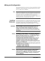
Wiring and Configuration
This section describes how to connect user wiring to each of the three Switch
M-Modules. It also describes how to configure the HP E2272A as a dual
8-to-1 or a single 16-to-1 multiplexer.
Note
The procedures in this section assume the M-Module(s) have already been
installed into an M-Module Carrier. Since installation is dependent on the
carrier used, instructions for installing M-Modules into the carrier are not
included here. Refer to your M-Module carrier documentation for
installation instructions. Each Hewlett-Packard M-Module is shipped with
identifying labels that you should install on the carrier.
Identfying
M-Modules
The Switch M-Modules have a module ID number printed on the PC-board.
The ID number consists of a model number prefix/PC-board number suffix.
For example, “E2270-66501” is the ID number for the HP E2270
M-Module. ID number locations are shown in Figures 1-2, 1-3, and 1-4.
WARNING
SHOCK HAZARD. Only service-trained personnel who are
aware of the hazards involved should install, remove, or
configure the modules. Before installing or removing any
module or carrier, disconnect power from the mainframe and
user wiring.
Caution
MAXIMUM VOLTAGE/CURRENT. The maximum voltage that
may be applied to any connector on the HP E2270A, E2271A, or
E2272A is 200 VDC, 125 VAC rms, or 175 VAC peak. These
limits apply only if the product is installed in a
humidity-controlled (<60% RH) environment where airborne
contaminants and transients are controlled, and NO relay
connection is made to power mains. If these conditions
CANNOT be maintained, then the maximum voltage is 60 VDC,
48 VAC-rms or 68 VAC-peak.
The maximum current (non-inductive) that may be appied to the
HP E2270A, E2271A, or E2272A is:
Per Switch: 2 ADC, 2 AAC peak
Per Module: 8 ADC, 8 AAC peak
Caution
STATIC ELECTRICITY. Static electricity is a major cause of
component failure. To prevent damage to the electrical
components on an M-Module or the carrier, observe anti-static
techniques whenever installing, removing, or working on a
carrier or M-Module.
Getting Started
13
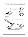
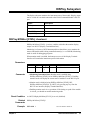
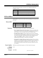
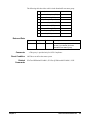
Assembling the
Field Wiring
Connector
Each Switch M-Module includes a 44-pin connector and hood (HP kit part
number E2273-01203). You must supply your own cable. The drawing
below shows how to connect wiring and assemble the connector and hood.
1. If necessary, disassemble
the connector hood. Discard
the three self-tapping screws
supplied with the hood.
2. Release the latch
on the side of the hood.
3. Assemble bezel and
cable clamp before wiring
cable to connector.
4. Use 24 gauge or smaller stranded wire.
Strip wires 1/8”
5. Solder wires to connector.
6. Assemble connector using supplied machine
screws. DO NOT overtighten screws.
Figure 1-1. Assembling the Field Wiring Connector
14
Getting Started
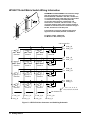
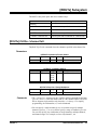
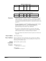
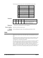
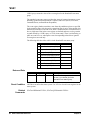
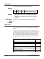
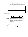
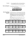
HP E2270A Form A Switch Wiring Information
MAXIMUM VOLTAGE/CURRENT. The maximum voltage
that may be applied to any connector on the HP
E2270A, E2271A, or E2272A is 200 VDC, 125 VAC rms,
or 175 VAC peak--these limits apply only if the product
is installed in a humidity-controlled (<60% RH)
environment where airborne contaminants and
transients are controlled, and there is NOT a relay
connection made to power mains. If these conditions
CANNOT be maintained, then the maximum voltage is
60 VDC, 48 VAC-rms or 68 VAC-peak.
The maximum current (non-inductive) that may be
applied to the HP E2270A, E2271A, or E2272A is:
Per Switch: 2 ADC, 2 AAC peak
Per Module: 8 ADC, 8 AAC peak
User
Connector
Pins
Channel 0
User
Connector
Pins
Channel 8
1
16
CH0_NO
CH0_COM
2
17
CH1_NO
CH1_COM
3
18
CH2_NO
CH2_COM
Channel 1
9
24
CH8_NO
CH8_COM
10
25
CH9_NO
CH9_COM
11
26
CH10_NO
CH10_COM
12
27
CH11_NO
CH11_COM
13
28
CH12_NO
CH12_COM
14
29
CH13_NO
CH13_COM
15
30
CH14_NO
CH14_COM
43
44
CH15_NO
CH15_COM
Channel 9
Channel 2
Channel 10
Channel 11
Channel 3
4
19
CH3_NO
CH3_COM
5
20
CH4_NO
CH4_COM
6
21
CH5_NO
CH5_COM
7
22
CH6_NO
CH6_COM
8
23
CH7_NO
CH7_COM
Channel 4
Channel 12
Channel 5
Channel 13
Channel 14
Channel 6
Channel 7
Channel 15
31 - 42
Figure 1-2. HP E2270A User Connector and Switching Schematic
Getting Started
15
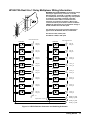
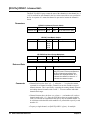
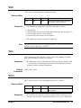
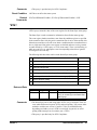
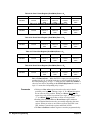
HP E2271A 4x4 Matrix Switch Wiring Information
MAXIMUM VOLTAGE/CURRENT. The maximum voltage
that may be applied to any connector on the HP
E2270A, E2271A, or E2272A is 200 VDC, 125 VAC rms,
or 175 VAC peak--these limits apply only if the product
is installed in a humidity-controlled (<60% RH)
environment where airborne contaminants and
transients are controlled, and there is NOT a relay
connection made to power mains. If these conditions
CANNOT be maintained, then the maximum voltage is
60 VDC, 48 VAC-rms or 68 VAC-peak.
The maximum current (non-inductive) that may be
applied to the HP E2270A, E2271A, or E2272A is:
Per Switch: 2 ADC, 2 AAC peak
Per Module: 8 ADC, 8 AAC peak
User Connector Pins
Channel 00
Channel 01
Channel 10
Channel 11
Channel 20
Channel 21
Channel 30
Channel 31
Channel 02
Channel 12
Channel 22
Channel 32
4
20
ROW_0_HI
ROW_0_LO
6
22
ROW_1_HI
ROW_1_LO
8
24
ROW_2_HI
ROW_2_LO
10
26
ROW_3_HI
ROW_3_LO
Channel 03
Channel 13
Channel 23
Channel 33
1, 3, 5, 7, 9, 11, 13, 14, 17,
19, 21, 23, 25, 27, 29, 32-44
User Connector Pins
2 COL_0_LO
18 COL_0_HI
16 COL_1_LO
31 COL_1_HI
12 COL_2_LO
28 COL_2_HI
15 COL_3_LO
30 COL_3_HI
Figure 1-3. HP E2271A User Connector and Switching Schematic
16
Getting Started
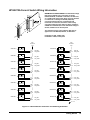
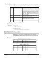
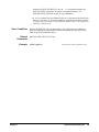
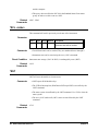
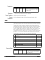
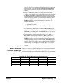
HP E2272A Dual 8-to-1 Relay Multiplexer Wiring Information
MAXIMUM VOLTAGE/CURRENT. The maximum voltage
that may be applied to any connector on the HP
E2270A, E2271A, or E2272A is 200 VDC, 125 VAC rms,
or 175 VAC peak--these limits apply only if the product
is installed in a humidity-controlled (<60% RH)
environment where airborne contaminants and
transients are controlled, and there is NOT a relay
connection made to power mains. If these conditions
CANNOT be maintained, then the maximum voltage is
60 VDC, 48 VAC-rms or 68 VAC-peak.
The maximum current (non-inductive) that may be
applied to the HP E2270A, E2271A, or E2272A is:
Per Switch: 2 ADC, 2 AAC peak
Per Module: 8 ADC, 8 AAC peak
User Connector Pins
Channel 0
User Connector Pins
Channel 8
1
2
CH0_HI
CH0_LO
Channel 1
25
9
CH8_HI
CH8_LO
26
10
CH9_HI
CH9_LO
27
11
CH10_HI
CH10_LO
28
12
CH11_HI
CH11_LO
13
29
CH12_HI
CH12_LO
15
14
CH13_HI
CH13_LO
30
44
CH14_HI
CH14_LO
43
42
CH15_HI
CH15_LO
8
24
MUXB_HI_COM
MUXB_LO_COM
23
7
MUXA_HI_COM
MUXA_LO_COM
Channel 9
18
33
CH1_HI
CH1_LO
17
32
CH2_HI
CH2_LO
Channel 2
Channel 10
Channel 3
Channel 11
16
31
CH3_HI
CH3_LO
Channel 4
Channel 12
22
6
CH4_HI
CH4_LO
Channel 5
Channel 13
21
5
CH5_HI
CH5_LO
20
4
CH6_HI
CH6_LO
Channel 6
Channel 14
Channel 7
Channel 15
19
3
CH7_HI
CH7_LO
34 - 41
Single/Dual Mux. Jumpers
Figure 1-4. HP E2272A User Connector and Switching Schematic
Getting Started
17
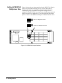
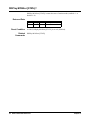
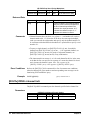
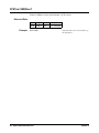
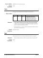
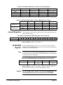
Setting HP E2272A
Multiplexer Size
Figure 1-4 shows the two jumper positions for the HP E2272A. When in
position A (jumper not connecting one row of pins), the module is
configured as a dual 8-to-1 multiplexer. When in position B (jumper
connecting all pins), the module is configured as a single 16-to-1
multiplexer. The HP E2272A leaves the factory with the jumper placed in
position A (dual 8-to-1 multiplexer). If you need to change this jumper
postion, it must be done before installing the M-Module onto the carrier.
A
Dual 8-to-1 Multiplexer Position
B
Single 16-to-1 Multiplexer Position
Figure 1-5. HP E2272A Jumper Positions
18
Getting Started
Chapter 2
SCPI Programming
Using This Chapter
This chapter contains SCPI program examples that demonstrate how to read
a module ID, perform self-test, and open and close channels. The program
examples are written in C language and can be used on any of the three
Switch M-Modules. To run one of these programs you must have the HP
SICL Library, the HP VISA Library, an HP-IB interface module installed in
an external PC, an HP E1406 Command Module, and a Switch M-Module
installed on the HP E2251 Carrier.
Example1: Initial Operation
The following example reads the module ID string, performs module
self-test, and displays the results. This program can be used on any of the
three Switch M-Modules.
#include <visa.h>
#include <stdio.h>
#include <stdlib.h>
/* Interface address is 9, M-Module secondary address is 3*/
#define INSTR_ADDR “GPIB0::9::3::INSTR”
int main()
{
ViStatus errStatus;
ViSession viRM;
ViSession m_mod;
char id_string[256];
char selftst_string[256];
/*Status from each VISA call*/
/*Resource mgr. session */
/* M-module session */
/*ID string*/
/*self-test string*/
/* Open the default resource manager */
errStatus = viOpenDefaultRM ( &viRM);
if(VI_SUCCESS > errStatus){
printf(“ERROR: viOpenDefaultRM() returned 0x%x\n”,errStatus);
return errStatus;}
/* Open the M-Module instrument session */
errStatus = viOpen(viRM,INSTR_ADDR, VI_NULL,VI_NULL,&m_mod);
if(VI_SUCCESS > errStatus){
printf(“ERROR: viOpen() returned 0x%x\n”,errStatus);
return errStatus;}
(program continued on next page)
Chapter 2
SCPI Programming
19
/* Reset the M-Module */
errStatus = viPrintf(m_mod, “*RST\n”);
if(VI_SUCCESS > errStatus){
printf(“ERROR: viPrintf() returned 0x%x\n”,errStatus);
return errStatus;}
/* Perform M-Module Self-Test */
errStatus = viQueryf(m_mod,”*TST?\n”,”%t”,selftst_string);
if (VI_SUCCESS > errStatus) {
printf(“ERROR: viPrintf() returned 0x%x\n”,errStatus);
return errStatus;}
printf(“Self Test Result is %s\n”,selftst_string);
/* Query the M-Module ID string */
errStatus = viQueryf(m_mod,”*IDN?\n”,”%t”,id_string);
if (VI_SUCCESS > errStatus) {
printf(“ERROR: viPrintf() returned 0x%x\n”,errStatus);
return errStatus;}
printf(“ID is %s\n”,id_string);
/* Close the M_Module Instrument Session */
errStatus = viClose (m_mod);
if (VI_SUCCESS > errStatus) {
printf(“ERROR: viClose() returned 0x%x\n”,errStatus);
return 0;}
/* Close the Resource Manager Session */
errStatus = viClose (viRM);
if (VI_SUCCESS > errStatus) {
printf(“ERROR: viClose() returned 0x%x\n”,errStatus);
return 0;}
return VI_SUCCESS;
}
20
SCPI Programming
Chapter 2
Closing and Opening Channels
The [ROUTe]:CLOSe<channel_list> command closes one or more
channels on a Switch M-Module. The [ROUTe]:OPEN<channel_list>
opens one or more channels.
Note
The [ROUTe]: portion of the command is optional syntax and can be
omitted. For example, the command [ROUTe]:CLOSE <channel list> can
be shortened to CLOSE <channel list>.
Note
HP E2272 Relay Multiplexer Note: In the dual 8-to-1 mode,
ROUTe:CLOSe ensures that only one relay is closed at a time in each
multiplexer. In the single 16-to-1 mode, ROUTe:CLOSe ensures that only
one relay is closed at a time on the entire module.
Channel Lists
The <channel list> parameter in the CLOSE or OPEN command has the
form (@ccnn), where cc is the card number and nn is the channel number.
Note
The SCPI Driver supports single modules only, therefore cc is always 1. To
simplify programming, the card number (cc) can be eliminated. The
remainder of this manual will use the shortened (no card number) channel
list format (@nn).
You can specify a single channel (@nn), use commas to specify multiple
channels (@nn,nn,...), or use a colon to specify a range of channels
(@nn:nn). You can also specify any combination of single channels,
multiple channels, and channel ranges. Some examples:
CLOS (@00,03)
!Close channels 00 and 03
OPEN (@01,02,03,10)
! Open channels 01, 02, 03 and 10
OPEN (@00:07)
! Open channels 00 through 07
CLOS (@02:05,07,09:11)
! Close channels 02 through 05, 07, and 09 through 11
Note
Chapter 2
A range of channels (@nn:nn) must be specified in ascending order, that is
lower channel number on the left, higher number on the right.
SCPI Programming
21
Switch M-Module
Channel Numbers
• The HP E2270’s channels are numbered 00 through 15.
• The HP E2271’s channels aare numbered 00 through 03, 10 through
13, 20 through 23, and 30 through 33.
• The HP E2272’s channels are numbered 00 through 15.
Example 2: Closing Multiple Channels
The following example closes channel 01 and channels 10 through 13 on a
Switch M-Module. The program then opens channels 01 and 11. This
program can be used on any of the three Switch M-Modules. The program
assumes an M-Module secondary address of 3 and an interface address of 9.
Note
HP E2272A Relay Multiplexer Note: The driver will ensure that only one
channel per multiplexer is closed at a time. If multiple channels are
specified in a channel list (as in the following program), then only the last
channel for each multiplexer specified in the channel list will be closed
when the CLOSe command completes (channel 13 in this example).
#include <visa.h>
#include <stdio.h>
#include <stdlib.h>
/* Interface address is 9, M-Module secondary address is 3*/
#define INSTR_ADDR “GPIB0::9::3::INSTR”
int main()
{
ViStatus errStatus;
ViSession viRM;
ViSession m_mod;
/*Status from each VISA call*/
/*Resource mgr. session */
/* M-module session */
/* Open the default resource manager */
errStatus = viOpenDefaultRM ( &viRM);
if(VI_SUCCESS > errStatus){
printf(“ERROR: viOpenDefaultRM() returned 0x%x\n”,errStatus);
return errStatus;}
/* Open the M-Module instrument session */
errStatus = viOpen(viRM,INSTR_ADDR, VI_NULL,VI_NULL,&m_mod);
if(VI_SUCCESS > errStatus){
printf(“ERROR: viOpen() returned 0x%x\n”,errStatus);
return errStatus;}
/* Reset the M-Module */
errStatus = viPrintf(m_mod, “*RST\n”);
if(VI_SUCCESS > errStatus){
printf(“ERROR: viPrintf() returned 0x%x\n”,errStatus);
return errStatus;}
(program continued on next page)
22
SCPI Programming
Chapter 2
/* Close channels 1 and 10 through 13 on the M-Module */
errStatus = viPrintf(m_mod,”ROUT:CLOS (@01,10:13)\n”);
if (VI_SUCCESS > errStatus) {
printf(“ERROR: viPrintf() returned 0x%x\n”,errStatus);
return errStatus;}
/* Open channels 1 and 11 on the M-Module */
errStatus = viPrintf(m_mod,”ROUT:OPEN (@01,11)\n”);
if (VI_SUCCESS > errStatus) {
printf(“ERROR: viPrintf() returned 0x%x\n”,errStatus);
return errStatus;}
/* Close the M_Module Instrument Session */
errStatus = viClose (m_mod);
if (VI_SUCCESS > errStatus) {
printf(“ERROR: viClose() returned 0x%x\n”,errStatus);
return 0;}
/* Close the Resource Manager Session */
errStatus = viClose (viRM);
if (VI_SUCCESS > errStatus) {
printf(“ERROR: viClose() returned 0x%x\n”,errStatus);
return 0;}
return VI_SUCCESS;
}
Chapter 2
SCPI Programming
23
24
SCPI Programming
Chapter 2
Chapter 3
SCPI Command Reference
Using This Chapter
This chapter describes the Standard Commands for Programmable Instruments
(SCPI) command set and the IEEE-488.2 Common Commands for the HP E2270,
E2271, and E2272 Switch M-Modules. This chapter contains the following sections:
• Command Fundamentals . . . . . . . . . . . . . . . . . . . . . . . . . . . . . . . . . .
• SCPI Commands . . . . . . . . . . . . . . . . . . . . . . . . . . . . . . . . . . . . . . . .
• Common Command Reference . . . . . . . . . . . . . . . . . . . . . . . . . . . . .
• SCPI Command Quick Reference . . . . . . . . . . . . . . . . . . . . . . . . . . .
• Common Command Quick Reference . . . . . . . . . . . . . . . . . . . . . . . .
page 25
page 28
page 43
page 53
page 54
Command Fundamentals
Commands are separated into two types: IEEE 488.2 Common commands and SCPI
commands.
Common
Command
Format
The IEEE 488.2 standard defines the Common commands that perform functions
like reset, self-test, status byte query, etc. Common commands are four or five
characters in length, always begin with the asterisk character ( *), and may include
one or more parameters. The command keyword is separated from the first
parameter by a space character. Some examples of Common commands are shown
below:
*RST
SCPI
Command
Format
*ESR 32
*STB?
The SCPI commands perform functions like closing switches, making
measurements, and querying instrument states or retrieving data. A subsystem
command structure is a hierarchical structure that usually consists of a top level (or
root) command, one or more lower-level commands, and their parameters. The
following example shows part of a typical subsystem:
[ROUTe:]
CLOSe <channel_list>
[ROUTe: ]is the root command, CLOSe is second-level command with parameter.
Command
Separator
A colon (:) always separates one command from the next lower-level command as
shown below:
[ROUTe:]OPEN?
Abbreviated
Commands
Chapter 3
The command syntax shows most commands as a mixture of upper- and lowercase
letters. The uppercase letters indicate the abbreviated spelling for the command. For
SCPI Command Reference
25
shorter program lines, send the abbreviated form. For better program readability, you
may send the entire command. The instrument will accept either the abbreviated
form or the entire command.
For example, if the command syntax shows MEASure, then MEAS and MEASURE
are both acceptable forms. Other forms of MEASure, such as MEASU or MEASUR
will generate an error. You may use upper- or lowercase letters. Therefore,
MEASURE, measure, and MeAsUrE are all acceptable.
Implied
Commands
Implied commands are those which appear in square brackets ([ ]) in the command
syntax. (Note that the brackets are not part of the command and are not sent to the
instrument.) Suppose you send a second-level command but do not send the
preceding implied command. In this case, the instrument assumes you intend to use
the implied command and it responds as if you had sent it.
Examine the [ROUTe:] subsystem shown below:
[ROUTe:]
CLOSe <channel_list>
CLOSe? <channel_list>
OPEN <channel_list>
OPEN? <channel_list>
The root command [ROUTe:] is an implied command (indicated by square brackets
[ ]). To close relays in a channel list, you can send either of the following command
statements:
[ROUTe:]CLOSe (@100:103) or CLOSe (@100:103)
Parameters
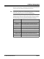
Parameter Types. The following table contains explanations and examples of
parameter types you might see later in this chapter.
Parameter Type
Explanations and Examples
Numeric
Accepts all commonly used decimal representations of
numbers including optional signs, decimal points, and
scientific notation.
123, 123E2, -123, -1.23E2, .123, 1.23E-2, 1.23000E-01.
Special cases include MIN, MAX, and INF.
Boolean
Represents a single binary condition that is either true
or false.
ON, OFF, 1, 0.
Linking
Commands
Linking IEEE 488.2 Common Commands with SCPI Commands. Use a
semicolon (;)between the commands. For example:
*RST;CLOS (@01)
26
SCPI Command Reference
or
OPEN (@02);*RST
Chapter 3
Linking Multiple SCPI Commands. Use both a semicolon (;)and a
colon (:) between the commands. For example:
CLOS (@02);:OPEN (@03)
Relay Numbering
All relays numbers have the form ccnn. Where cc represents the card number and nn
represents the channel number. The SCPI Driver supports single modules only,
therefore cc is always 1. To simplify programming, the card number (cc) can be
eliminated.
• Channel numbering on each Switch M-Module begins with channel 00.
• The HP E2270 supports channels 00 through 15.
• The HP E2271 supports channels 00 through 03, 10 through 13, 20 through 23,
and 30 through 33.
• The HP E2272 supports channels 00 through 15.
Channel Lists
The <channel list> parameter in the CLOSE or OPEN command has the form
(@ccnn), where cc is the card number and nn is the channel number.
Note
The SCPI Driver supports single modules only, therefore cc is always 1. To
simplify programming, the card number (cc) can be eliminated.
You can specify a single channel (@nn), use commas to specify multiple channels
(@nn,nn,...), or use a colon to specify a range of channels (@nn:nn). You can also
specify any combination of single channels, multiple channels, and channel ranges.
Some examples:
CLOS (@00,03)
!Close channels 00 and 03
OPEN (@01,02,03,10)
! Open channels 01, 02, 03 and 10
OPEN (@00:07)
! Open channels 00 through 07
CLOS (@02:05,07,09:11)
! Close channels 02 through 05, 07, and 09 through 11
Note
Chapter 3
A range of channels (@nn:nn) must be specified in ascending order, that is
lower channel number on the left, higher number on the right.
SCPI Command Reference
27
DIAGnostic Subsystem
The DIAGnostic subsystem allows you to set and query the interrupt line used by the
M-Module and to run an extended hardware self-test.
Syntax
Description
:DIAGnostic
:INTerrupt
:LINE <intr_line> Sets VXI interrupt line on the HP E2251 Carrier
:LINE?
Returns VXI interrupt line being used by HP E2251 Carrier
:TEST?
Performs an extended hardware self-test
DIAGnostic:INTerrupt:LINE <intr_line>
DIAGnostic:INTerrupt:LINE <intr_line> sets the VXIbus interrupt line the module
will use and allows you to enable/disable interrupts.
Note
The VXIbus Interrupt Line is controlled by the VXIbus M-Module carrier NOT by
the M-Module. DIAGnostic:INTerrupt:LINE reprograms the HP E2251 M-Module
carrier. It will work properly only if the M-Module is installed in an HP E2251
M-Module carrier.
Parameters
Name
Type Range
<intr_line> int16 0 through 7
Comments
Reset Condition
Related
Commands
Example
28
Default Description
1
VXIbus interrupt line
•
Interrupts for an M-Module are automatically enabled whenever interrupt line
1 through 7 is selected (1 = default). To disable an M-Module from
interrupting, set the interrupt line to 0.
• When enabled to interrupt, a Switch M-Module asserts an interrupt whenever a
relay close/open operation has been performed ([ROUTe] Subsytem).
• Normally, the interrupt line does not have to be modified.
• If the interrupt line is changed, it may be necessary to re-configure the I/O
software and/or Resource Manager on the controlling computer.
*RST does not affect the interrupt line.
DIAGnostic:INTerrupt:LINE?
DIAG:INT:LIN 6
SCPI Command Reference
Set the module’s interrupt line to 6
Chapter 3
DIAGnostic:INTerrupt:LINE?
DIAGnostic:INTerrupt:LINE? returns the VXIbus interrupt line being used by the
module
Returned Data
Reset Condition
Related
Commands
Example
Type
Range
Default
Description
int16
0 through 7
1
VXIbus interrupt line
*RST does not affect the interrupt line.
DIAGnostic:INTerrupt:LINE
DIAG:INT:LINE?
Query the interrupt level
DIAGnostic:TEST?
DIAGnostic:TEST? performs an extensive relay self-test and returns a numerical
and string response indicating the results of the test.
Caution
Chapter 3
The extended self-test will open and close each relay in the module.
Before performing this test, make sure that external devices will not be
affected by these actions. It is recommended that external devices be
disconnected from the module while executing DIAGnostic:TEST?.
SCPI Command Reference
29
Returned Data
Type
Description of Numerical Response
int16, string 0 = self-test passed
Possible Strings Returned
“Self test passed”
1 = ERROR: status register
“Busy, full bit failed. Expect 4, got X”
“Busy, stuck at 0. Expect 1, got X”
“Init or full bit wrong. Expect X, got X”
2 = ERROR: register readback
“Readback reg X failed, expect 0, got X”
3 = ERROR: interrupt
“Interrupt failed VISA error X”
Comments
• DIAG:TEST? opens all relays and then closes each relay, one at a time. It then
waits for an interrupt and reads the register to verify that the relay actually
closed. If an interrupt does not occur, a 3 is returned indicating a missing
interrupt error. If the value that was read back does not match what was set, a 1
is returned indicating that there is a problem somewhere in the relay driver
circuitry. Following the self-test, all relays are left in the open state.
• A query response of 0 means that the module is operating properly, a non-zero
result means an error occurred.
• The extended self-test does not measure the actual relay state position to
ensure that it is closed or open, it only queries the state of the Control Register
circuitry. It may be possible to pass DIAGnostic:TEST? (return a 0) and still
have relay failures.
Reset Condition
Related
Commands
Example
30
*RST does not affect this query.
*TST?
DIAG:TEST?
SCPI Command Reference
Perform diagnostic test.
Chapter 3
DISPlay Subsystem
The display subsystem monitors the instrument state of the module. Display output
can be viewed on a terminal connected to the E1406 Command Module’s RS-232
port.
Syntax
Description
:DISPlay
:MONitor
[:STATe] <boolean> Enables or disables instrument state over RS-232
[:STATe?]
Returns the state of monitor mode(enabled/disabled)
DISPlay:MONitor:[STATe] <boolean>
DISPlay:MONitor:[STATe] <boolean> enables or disables the monitor display
output over RS-232 (Display Terminal Interface).
Monitoring is a feature of SCPI Instrument drivers that allows you to monitor the
status of the module while it being controlled remotely (i.e. over HP-IB). Monitoring
mode is useful for debugging programs.
When monitor mode is enabled, the bottom two rows of the Display Terminal
Interface will contain the instrument specific information.
Parameters
Name
Type
Range
<boolean> boolean ON, OFF,
0, 1
Comments
Default Description
0
enables or disables monitor mode
• Monitoring Instrument State: Monitor mode is enabled using
DISPlay:MONitor:[STATe] ON or DISPlay:MONitor:[STATe] 1. Enabling
monitor mode will display the current state of module over the RS-232 port.
• Monitor mode is disabled using DISPlay:MONitor:[STATe] OFF,
DISPlay:MONitor:[STATe] 0, by *RST, or by pressing any key from the
RS-232 user interface (Display Terminal Interface).
• Enabling monitor mode slows operations. If the timing or speed of the module
is critical, you should not enable monitoring mode.
Reset Condition
Related
Commands
Example
Chapter 3
At *RST, DISplay:MONitor:[STATe] is set to 0 (disabled).
DISPlay:MONitor:[STATe]?
DISP:MON 1
Turn the monitor mode on
SCPI Command Reference
31
DISPlay:MONitor:[STATe]?
DISPlay:MONitor:[STATe]? returns the state of monitor mode (enabled = 1 or
disabled = 0).
Returned Data
Type
Range Default Description
boolean 0,1
Reset Condition
Related
Commands
32
0
State of Monitor Mode
At *RST, DISplay:MONitor:[STATe] is set to 0 (disabled).
DISPlay:MONitor:[STATe]
SCPI Command Reference
Chapter 3
[ROUTe] Subsystem
The ROUTe subsystem opens and closes channel relays.
Syntax:
Description
[:ROUTe]
:CLOSe <channel list>
Closes channels specified in <channel list>
:CLOSe? <channel list>
Returns close state of channels in <channel list>
:OPEN <channel list>
Opens channels specified in <channel list>
:OPEN? <channel list>
Returns open state of channels in <channel list>
[ROUTe]:CLOSe <channel list>
The [ROUTe]:CLOSe command closes the channels specified in the channel list.
Parameters
Name
HP E2270 16-Channel Form A Switch
Type
Range Default Description
<channel list> channel list 00-15
Name
none
List of channels to close
HP E2272 Dual 8-to-1 Relay Multiplexer
Type
Range Default Description
<channel list> channel list 00-15
Comments
List of channels to close
HP E2271 4 x 4 Matrix Switch
Type
Range Default Description
<channel list> channel list 00-03,
10-13,
20-23,
30-33
Name
none
none
List of channels to close
• The <channel list> parameter in the CLOSE or OPEN command has the form
(@ccnn), where cc is the card number and nn is the channel number. The SCPI
Driver supports single modules only, therefore cc is always 1. To simplify
programming, the card number (cc) can be eliminated.
• You can specify a single channel (@nn), use commas to specify multiple
channels (@nn,nn,...), or use a colon to specify a range of channels (@nn:nn).
You can also specify any combination of single channels, multiple channels,
and channel ranges. For example, to close only channel 3, use
Chapter 3
SCPI Command Reference
33
[ROUTe]:CLOSe (@ 03); to close channels 5 and 8, use [ROUTe]:CLOSe
(@05,08); to close channels 3 through 7, use [ROUTe]:CLOSe (@ 03:07); to
close channels 2 through 5 and 7 through 9, use [ROUTe]:CLOSe (@ 02:05,
07:09).
• A range of channels (@nn:nn) must be specified in ascending order, that is
lower channel number on the left, higher number on the right.
• The sequence in which multiple channels are closed in a single CLOSe
command is not guaranteed. To ensure sequential operation, send multiple
CLOSe command with one channel specified per command.
• If any of the channels in the channel list cannot be closed, an execution error is
reported.
Additional
HP E2272 Dual
8-to-1 Relay
Multiplexer
Comments
• The HP E2272 SCPI Driver will open all channels in a multiplexer before
closing any relays specified in the channel list. This provides a “break before
make” switching operation.
• When the HP E2272A is configured as Dual 8-to-1 multiplexers, each
multiplexer is independent. This means that channels are opened and closed on
a per multiplexer basis. For example, executing [ROUTe]:CLOSe (@ 12), will
open all channels in Multiplexer B (open channels 8 through 15) and then
close channel 12. Channels 0 through 7 (Multiplexer A) are not affected.
• When the HP E2272A is configured as a Single 16-to-1 multiplexer, every
channel is part of the same multiplexer. This means that closing any channel
will first open all other channels on the module. For example, executing
[ROUTe]:CLOSe (@ 12), will open all channels on the module (open channels
0 through 15) and then close channel 12
• The SCPI driver ensures that only one channel per multiplexer is closed at a
time. If multiple channels are specified in a channel list, then only the last
channel of each multiplexer specified in the channel list will be closed when
the [ROUTe]:CLOSe command completes.
• Multiple channels can be closed using register programming.
Reset Condition
34
*RST will open all relays.
SCPI Command Reference
Chapter 3
Error Conditions
The following are some of the most common error conditions relating to channel
lists. Error numbers and corresponding error messages can be found using
SYSTem:ERRor? query.
Number
Message
Probable Cause
-222
“Data out of range”
An invalid channel range was specified. One or
more of the range channel elements is out or range.
Valid ranges are from 0-15 or 100-115. Both channel
elements in the range need to be of the same type.
For example: (@4:6) specifies channels four, five,
and six. (@1:115) will generate an error, since you
can not mix cc types.
2000
“Invalid card number”
A channel element was specified using the ccnn
format. And cc was not 00 or 01.
2001
“Invalid channel number” A channel element is improperly specified. Valid
channel numbers are 0-15 or 100-115.
2011
“Empty channel list”
Related
Commands
Examples
No channel element was specified in the channel
list.
[ROUTe]:CLOSe?, [ROUTe]:OPEN
CLOS (@00,03)
!Close channels 00 and 03
CLOS (@02:05,07,09:11)
! Close channels 02 through 05, 07, and 09 through 11
[ROUTe]:CLOSe? <channel list>
The [ROUTe]:CLOSe? returns the state of the channel(s) in the channel list. A 1 or
0 is returned for each channel in the list--in the same order as was specified in the
list. A response of 1 means the channel is closed and a 0 means the channel is open.
Parameters
Name
HP E2270 16-Channel Form A Switch
Type
Range Default Description
<channel list> channel list 00-15
Name
List of channels to query
HP E2271 4x4 Matrix Switch
Type
Range Default Description
<channel list> channel list 00-03,
10-13,
20-23,
30-33
Chapter 3
none
none
List of channels to query
SCPI Command Reference
35
Name
HP E2272 Dual 8-to-1 Relay Multiplexer
Type
Range Default Description
<channel list> channel list 00-15
none
List of channels to query
Returned Data
Comments
Type
Range
Default
Description
string
0,1
none
A string containing a comma separated
array of 0’s and 1’s that corresponds to
the list of channels specified in the
<channel list> input parameter. A “0”
indicates the channel is open. A “1”
indicates the channel is closed.
• Channel elements have the form ccnn, where cc = card number (01) and nn =
channel number (00 - 15). Since the SCPI driver does not support multiple
cards you can omit the card number and specify only the channel number. To
be consistent with other HP Switch modules it is permissible to specify a card
number of 1.
• To query a single channel, use [ROUTe]:CLOSe? (@ nn); for multiple
channels use [ROUTe]:CLOSe? (@ nn, nn, …); for sequential channel, use
[ROUTe]:CLOSe? (@ nn:nn); for groups of sequential channels, use
[ROUTe]:CLOSe? (@ nn:nn, nn:nn); or any combination.
• The instrument driver returns a 1 or 0 for each channel in the list, in the same
order that the list was specified. A response of 1 means the channel is closed
and a 0 means the channel is open. Note: The response of the
[ROUTe]:CLOSe? query is the opposite of [ROUTe]:OPEN? query.
Error Conditions
Example
Refer to the [ROUTe]:CLOSe command for a list of common error conditions
related to channel lists. Error numbers and corresponding error messages can be
found using SYSTem:ERRor? query.
CLOS? (@00,03)
Query channels 0 & 3.
[ROUTe]:OPEN <channel list>
The [ROUTe]:OPEN command opens the channels specified in the channel list.
Parameters
Name
HP E2270 16-Channel Form A Switch
Type
Range Default Description
<channel list> channel list 00-15
36
SCPI Command Reference
none
List of channels to open
Chapter 3
HP E2271 4x4 Matrix Switch
Type
Range Default Description
Name
<channel list> channel list 00-03,
10-13,
20-23,
30-33
Name
List of channels to open
HP E2272 Dual 8-to-1 Relay Multiplexer
Type
Range Default Description
<channel list> channel list 00-15
Comments
none
none
List of channels to open
• Channel elements have the form ccnn, where cc = card number (01) and nn =
channel number (00 - 15). Since the SCPI driver does not support multiple
cards you can omit the card number and specify only the channel number. To
be consistent with other HP Switch modules it is permissible to specify a card
number of 1.
• To open a single channel, use [ROUTe]:OPEN (@ nn); for multiple channels
use [ROUTe]:OPEN (@ nn, nn, …); for sequential channels, use
[ROUTe]:OPEN (@ nn:nn); for groups of sequential channels, use
[ROUTe]:OPEN (@ nn:nn, nn:nn); or any combination.
• The sequence in which multiple channels are opened in a single OPEN
command is not guaranteed. To ensure sequential operation, send multiple
OPEN command with only one channel specified per command.
• If any of the channels in the channel list cannot be opened, an execution error
is reported.
Reset Condition
*RST will open all relays.
Error Conditions
Refer to the [ROUTe]:CLOSe command for a list of common error conditions
related to channel lists. Error numbers and corresponding error messages can be
found using SYSTem:ERRor? query.
Related
Commands
Examples
[ROUTe]:OPEN?, [ROUTe]:CLOSe
OPEN (@01,02,03,10)
! Open channels 01, 02, 03 and 10
OPEN (@00:07)
! Open channels 00 through 07
Chapter 3
SCPI Command Reference
37
[ROUTe]:OPEN? <channel list>
The [ROUTe]:OPEN? query returns the state of the channel(s) in the channel list. A
1 or 0 is returned for each channel in the list--in the same order as was specified in
the list. A response of 1 means the channel is open and a 0 means the channel is
closed.
Parameters
Name
H[ E2270 16-Channel Form A Switch
Type
Range Default Description
<channel list> channel list 00-15
Name
List of channels to query
HP E2271 4x4 Matrix Switch
Type
Range Default Description
<channel list> channel list 00-03,
10-13,
20-23,
30-33
Name
none
none
List of channels to query
HP E2272 Dual 8-to-1 Relay Multiplexer
Type
Range Default Description
<channel list> channel list 00-15
none
List of channels to query
Returned Data
Comments
Type
Range
Default
Description
string
0,1
none
A string containing a comma separated
array of 0’s and 1’s that corresponds to
the list of channels specified in the
<channel list> input parameter. A “0”
indicates the channel is closed. A “1”
indicates the channel is open.
• Channel lists have the form "(@ ... )", where the “...” is replaced a comma
separated list of channel elements. Channel lists can also include a range of
channel elements. This is specified by separating the starting channel elements
and ending channel elements with a colon ":". You can combine individual
channels and ranges.
• Channel elements have the form ccnn, where cc = card number (01) and nn =
channel number (00 - 15). Since the SCPI driver does not support multiple
cards you can omit the card number and specify only the channel number. To
be consistent with other HP switch modules it is permissible to specify a card
number of 1.
• To query a single channel, use [ROUTe]:OPEN? (@ nn);
38
SCPI Command Reference
for multiple
Chapter 3
channels use [ROUTe]:OPEN? (@ nn, nn, …); for sequential channel, use
[ROUTe]:OPEN? (@ nn:nn); for groups of sequential channels, use
[ROUTe]:OPEN? (@ nn:nn, nn:nn); or any combination.
• A 1 or 0 is returned for each channel in the list--in the same order specified in
the list. A response of 1 means the channel is open and a 0 means the channel
is closed. Note: The response of the [ROUTe]:OPEN? query is the opposite of
[ROUTe]:CLOSe? query.
Error Conditions
Related
Commands
Example
Chapter 3
Refer to the [ROUTe]:CLOSe command for a list of common error conditions
related to channel lists. Error numbers and corresponding error messages can be
found using SYSTem:ERRor? query.
[ROUTe]:OPEN, [ROUTe]:CLOSe
OPEN? (@00,02)
Querying the states of channels 0 & 2.
SCPI Command Reference
39
STATus Subsystem
SCPI uses four status groups - the Status Byte, the Standard Event status group, the
Operation status group, and the Questionable Data status group.
Note
This subsystem is included in the Switch M-Modules SCPI Driver for compatibility
reasons only. None of the events in the STATus:OPERation or
STATus:QUEStionable register are used by the Switch M-Modules.
Each status group consists of a condition register, transition filters, event register,
and enable register. The STATus subsystem controls those commands and queries
that affect the Operation status group and the QUEStionable status group.
Syntax:
Description
:STATus
:OPERation
:CONDition?
Returns condition register of operation status group
:ENABle <mask> Sets enable register of operation status group
:ENABle?
Returns enable register of operation status group
:EVENt?
Returns event register of operation status group
:PRESet
Clears operation & questionable enable registers
:QUEStionable
:CONDition?
Returns condition register of questionable status group
:ENABle <mask> Sets enable register of questionable status group
40
SCPI Command Reference
:ENABle?
Returns enable register of questionable status group
:EVENt?
Returns event register of questionable status group
Chapter 3
SYSTem Subsystem
The SYSTem subsystem allows you to query error conditions and the SCPI
compliance version.
Syntax:
Description
:SYSTem
:ERRor?
Returns error number and message from error queue
:VERSion?
Returns SCPI Version compliance year
SYSTem:ERRor?
SYStem:ERRor? returns the error number and corresponding error message from the
error queue.
Returned Data
Type
Range
Default Description
int16
-32768 through 32767
none
string
Comments
Error number
Error message
• The response format is: error_number, “error description string”.
• Error Numbers/Message in the Error Queue: Each error generated by this
instrument driver stores an error number and corresponding error message in
the error queue. The error message can be up to 255 characters long.
• Clearing the Error Queue: An error number/message is removed from the
queue each time the SYSTem:ERRor? command is sent. The errors are cleared
on a first-in, first-out basis. When all errors have been read and the queue is
empty, SYSTem:ERRor? returns 0, “No error”. To clear all error
number/messages in the queue, execute the *CLS command.
• Maximum Error Numbers/Message in the Error Queue: The queue holds a
maximum of 30 error numbers/messages. If the queue overflows, the last error
number/message in the queue is replaced by -350, “Too many errors”. The
least recent error number/message remains in the queue and the most recent
are discarded.
Reset Condition
Related
Commands
Example
Chapter 3
*RST does not affect the error queue, use *CLS to clear the error queue.
*CLS
SYST:ERR?
Query the error queue.
SCPI Command Reference
41
SYSTem:VERSion?
SYStem:VERSion? returns the M-Module’s SCPI version.
Returned Data
Type
Range
Default Description
string “1990.0” none
Example
42
SYST:VER?
SCPI Command Reference
Error message
Returned value is the version number of
the SCPI driver.
Chapter 3
IEEE Common Commands
These commands are defined in the IEEE 488.2 standard and are found on most
SCPI instruments.
*CLS
*CLS clears all status groups and empties the error queue.
Comments
• All event registers are cleared. This includes the Standard Event Status
register, the OPERation event status register, and the QUEStionable data status
register.
• *CLS does not affect the enable bits in any of the status register groups. (The
SCPI command STATus:PRESet does clear the Operation Status Enable
register and the Questionable Data Enable registers).
• *CLS disables the Operation Complete (*OPC) and the Operation Complete
query (*OPC?).
• Use *CLS to clear the error queue. It typically follows *RST to reset the
module to a know state.
Reset Condition
Related
Commands
*RST does not affect the status system
STATus:OPERation:EVENt?, STATus:QUEStionable:EVENt?, *ESR?
*ESE <mask>
*ESE <mask> command sets the value of the enable register in the Standard Event
status group.
The standard event status group provides that status of common instrument events
including synchronization (Operation Complete) and Errors (Parser, Execution,
Command Errors, and Instrument Dependent).
The enable register specifies which bits in the event register can generate a summary
bit. The instrument logically ANDs corresponding bits in the event and enable
registers, and ORs all the resulting bits to obtain a summary bit. Summary bits are,
in turn, recorded in another register. The standard event status summary bit is
recorded in the Status Byte. Enable registers are read-write. Enable registers are not
affected by *CLS (Clear status). Querying enable registers does not affect them.
Chapter 3
SCPI Command Reference
43
The following table describes each bit in the Standard Event status group:
Bit Description
Decimal Value
0
Operation Complete (OPC)
1
1
Request Control (RQC)
2
2
Query Error (QYE)
4
3
Instrument Dependent (DDE) 8
4
Execution Error (EXE)
16
5
Command Error (CME)
32
6
User Request (URQ)
64
7
Power On (PON)
128
Parameter
Name
Type Range Default Description
<mask> int16 0 - 255
Comments
Reset Condition
Related
Commands
none
Bit mask indicating which enable bits
are set (1) or cleared (0) for the
Standard Event status group.
• This query is provided only for SCPI Compliance
*RST does not affect the status system
STATus:OPERation:ENABle, STATus:QUEStionable:ENABle, *ESE?
*ESE?
*ESE? query returns the value of the enable register in the Standard Event status
group.
The standard event status group provides that status of common instrument events
including synchronization (Operation Complete) and Errors (Parser, Execution,
Command Errors, and Instrument Dependent).
The enable register specifies which bits in the event register can generate a summary
bit. The instrument logically ANDs corresponding bits in the event and enable
registers, and ORs all the resulting bits to obtain a summary bit. Summary bits are,
in turn, recorded in another register. The standard event status summary bit is
recorded in the Status Byte. Enable registers are read-write. Enable registers are not
affected by *CLS (Clear status). Querying enable registers does not affect them.
44
SCPI Command Reference
Chapter 3
The following table describes each bit in the Standard Event status group:
Bit Description
Decimal Value
0
Operation Complete (OPC)
1
1
Request Control (RQC)
2
2
Query Error (QYE)
4
3
Instrument Dependent (DDE) 8
4
Execution Error (EXE)
16
5
Command Error (CME)
32
6
User Request (URQ)
64
7
Power On (PON)
128
Returned Data
Comments
Reset Condition
Related
Commands
Chapter 3
Type
Range
Default
Description
int16
0 - 255
none
Bit mask indicating which enable bits
are set (1) or cleared (0) for the
Standard Event status group.
• This query is provided only for SCPI Compliance
*RST does not affect the status system
STATus:OPERation:ENABle?, STATus:QUEStionable:ENABle?, *ESE
SCPI Command Reference
45
*ESR?
*ESR? query returns the value of the event register for the Standard Event status
group.
The standard event status group provides that status of common instrument events
including synchronization (Operation Complete) and Errors (Parser, Execution,
Command Errors, and Instrument Dependent).
The event register latches transition events from the condition register as specified
by the transition filter. Only the positive transition filter is active in the module, this
means that a transition event will occur when a condition makes a transition from a
low to a high state. Bits in the event register are latched, and once set, they remain
set until cleared by a *ESR? query or *CLS (clear status). There is no buffering; so
while an event bit is set, subsequent events corresponding to that bit are ignored.
Event registers are read only.
The following table describes each bit in the Standard Event status group:
Bit Description
Decimal Value
0
Operation Complete (OPC)
1
1
Request Control (RQC)
2
2
Query Error (QYE)
4
3
Instrument Dependent (DDE) 8
4
Execution Error (EXE)
16
5
Command Error (CME)
32
6
User Request (URQ)
64
7
Power On (PON)
128
Returned Data
Reset Condition
Related
Commands
46
Type
Range
Default
Description
int16
0 - 255
none
Bit mask indicating which enable bits
are set (1) or cleared (0) for the
Standard Event status group.
*RST does not affect the status system. Use *CLS to clear all event registers in the
status system.
STATus:OPERation:EVENt?, STATus:QUEStionable:EVENt?
SCPI Command Reference
Chapter 3
*IDN?
*IDN? query returns the module’s identification string.
Returned Data
Comments
Type
Range
Default
Description
string
none
none
Module identification string containing
the revision of the SCPI driver.
• The identification string returns four field (separated by commas)
1.
2.
3.
4.
Manufacturer
Model Number and, for E2272A only, Mode (either dual 8x1 or single 16x1)
Serial Number (returns 0, if not available)
Firmware Revision (returns 0 if not available)
• The identification string is less than 255 characters.
Note
The firmware revision is the revision of the SCPI driver. This is the only indication
of which version of the driver is installed.
*OPC
*OPC command will cause the OPC event to occur in the Standard Event status
group when all pending operations are complete.
Comments
• By enabling this bit to be reflected in the Status Byte Register (sending *ESE
1), you can ensure synchronization between the instrument and an external
computer or between multiple instruments.
Related
Commands
*ESE, *OPC?, *WAI
*OPC?
*OPC? Query returns a 1 when all pending operations are complete.
Returned Data
Comments
Type
Range
Default
Description
int16
1
none
Returns 1 when all pending operations
are complete
• By requiring your computer to read this response before continuing program
execution, you can ensure synchronization between one or more instruments
Chapter 3
SCPI Command Reference
47
and the computer.
• This query does not affect the OPC bit in the Standard Status Event status
group. In order to set this event use *OPC.
Related
Commands
*OPC, *WAI
*RCL <state>
This command will recall a previously saved state of the instrument.
Parameter
Name
Type Range Default Description
<state> int16 0 - 9
Comments
none
number used to describe where the
instrument state will be recalled.
• Ten different states can be recalled. They are numbered from 0 through 9.
• Instrument state can be stored using the save (*SAV) command.
Reset Condition
Related
Commands
Instrument state storage (*SAV & *RCL) is unchanged by reset (*RST)
*SAV
*RST
*RST will reset the module to a known state.
Comments
• *RST opens all M-Module relays
• The VXIbus Interrupt line (DIAGnostic:INTerrupt:LINE) is not affect by the
*RST command.
• The status system is unaffected by the *RST command. Use *CLS to clear the
status system.
• The save (*SAV) and recall (*RCL) states are not affected by the *RST
command.
Related
Commands
48
*CLS
SCPI Command Reference
Chapter 3
*SAV <state>
*SAV command will save the current state of the instrument.
Parameter
Name
Type Range Default Description
<state> int16 0 - 9
none
number used to describe where the
instrument state will be saved.
• Ten different states can be saved. They are numbered from 0 through 9.
Comments
• The instrument can be returned to a saved state using the recall (*RCL)
command.
Reset Condition
Related
Commands
Instrument state storage (*SAV & *RCL) is unchanged by reset (*RST)
*RCL
*SRE <mask>
*SRE <mask> command sets the value of the enable register in the Status Byte
status group.
The Status Byte is used to summarize information from all other status groups.
The enable register specifies which bits in the event register can generate a summary
bit. The instrument logically ANDs corresponding bits in the event and enable
registers, and ORs all the resulting bits to obtain a summary bit. Summary bits are,
in turn, recorded in another register. The standard event status summary bit is
recorded in the Status Byte. Enable registers are read-write. Enable registers are not
affected by *CLS (Clear status). Querying enable registers does not affect them.
The following table describes each bit in the Status Byte status group:
Chapter 3
Bit Description
Decimal Value
0
Instrument Dependent
1
1
Instrument Dependent
2
2
Instrument Dependent
4
3
Summary bit from the Questionable Data status group (QUE)
8
4
Messages available in the Output Queue (MAV)
16
5
Summary bit from the Standard Event status group (ESB)
32
6
Service Request (RQS)
64
7
Summary bit from the Standard Operation status group (OPR) 128
SCPI Command Reference
49
Parameters
Name
Type Range Default Description
<mask> int16 0 - 255
Related
Commands
Bit mask indicating which enable bits
are set (1) or cleared (0) for the Status
Byte status group.
• This query is provided only for SCPI Compliance
Comments
Reset Condition
none
*RST does not affect the status system
STATus:OPERation:ENABle, STATus:QUEStionable:ENABle, *ESE?
*SRE?
*SRE? query returns the value of the enable register in the Status Byte status group.
The Status Byte is used to summarize information from all other status groups.
The enable register specifies which bits in the event register can generate a summary
bit. The instrument logically ANDs corresponding bits in the event and enable
registers, and ORs all the resulting bits to obtain a summary bit. Summary bits are,
in turn, recorded in another register. The standard event status summary bit is
recorded in the Status Byte. Enable registers are read-write. Enable registers are not
affected by *CLS (Clear status). Querying enable registers does not affect them.
The following table describes each bit in the Status Byte status group:
Bit Description
Decimal Value
0
Instrument Dependent
1
1
Instrument Dependent
2
2
Instrument Dependent
4
3
Summary bit from the Questionable Data status group (QUE)
8
4
Messages available in the Output Queue (MAV)
16
5
Summary bit from the Standard Event status group (ESB)
32
6
Service Request (RQS)
64
7
Summary bit from the Standard Operation status group (OPR) 128
Returned Data
50
Type
Range
Default
Description
int16
0 - 255
none
Bit mask indicating which enable bits
are set (1) or cleared (0) for the Status
Byte status group.
SCPI Command Reference
Chapter 3
• This query is provided only for SCPI Compliance
Comments
Reset Condition
Related
Commands
*RST does not affect the status system
STATus:OPERation:ENABle?, STATus:QUEStionable:ENABle?, *ESE
*STB?
*STB? query returns the value of the event register for the Status Byte status group.
The Status Byte is used to summarize information from all other status groups.
The event register latches transition events from the condition register as specified
by the transition filter. Only the positive transition filter is active in the module, this
means that a transition event will occur when a condition makes a transition from a
low to a high state. Bits in the event register are latched, and once set, they remain
set until cleared by a *STB? query or *CLS (clear status). There is no buffering; so
while an event bit is set, subsequent events corresponding to that bit are ignored.
Event registers are read only.
The following table describes each bit in the Status Byte status group:
Bit Description
Decimal Value
0
Instrument Dependent
1
1
Instrument Dependent
2
2
Instrument Dependent
4
3
Summary bit from the Questionable Data status group (QUE)
8
4
Messages available in the Output Queue (MAV)
16
5
Summary bit from the Standard Event status group (ESB)
32
6
Service Request (RQS)
64
7
Summary bit from the Standard Operation status group (OPR) 128
Returned Data
Comments
Type
Range
Default
Description
int16
0 - 255
none
Bit mask indicating which events are
set (1) or cleared (0) in the Status Byte
status group.
• The Status Byte can be read using either *STB? or by a serial poll. There are
some subtle differences between *STB? and serial polling. You can use either
method to read the state of bits 0-5 and bit 7. Bit 6 is treated differently
depending on whether you use *STB? or serial poll. In general, use serial
polling inside interrupt service routines, not a *STB?.
• This query is provided only for SCPI Compliance
Chapter 3
SCPI Command Reference
51
Reset Condition
Related
Commands
*RST does not affect the status system
*SRE
*TST?
*TST? query will return the result of running the self-test routine. T
Returned Data
Comments
Type
Range
Default
Description
int16
0,1,2
none
Result of running the self-test.
0 = SUCCESS: self-test passed.
1 = ERROR: driver register images
does not match hardware image
2 = ERROR: interrupt not detected
• *TST? will not change the state of any relays. *TST tests only the Module
Control circuitry--*TST? may pass even though there may be a hardware
problem. A more comprehensive self-test which does change relay positions
can be performed using DIAGnostic:TEST?
• *TST? can return a 1, if you are register programming the module and using
the SCPI driver at the same time.
Related
Commands
DIAGnostic:TEST?
*WAI
*WAI command will not return until all pending operations have completed.
Comments
Related
Commands
52
• This command is identical to *OPC? except that it does not return a value.
*OPC?
SCPI Command Reference
Chapter 3
SCPI Command Quick Reference
Keyword
Parameters
Notes
Description
:DIAGnostic
:INTerrupt
:LINE
<intr_line>
:TEST?
Changes VXI interrupt line
[query only]
Performs extended hardware self-test
:DISPlay
:MONitor
<boolean>
Displays instrument state over RS-232
:CLOSe
<channel list>
Closes relays
:OPEN
<channel list>
Opens relays (for HP E2270 & E2271
only)
[:STATe]
[:ROUTe]
:STATus
:OPERation
:CONDition?
:ENABle
[query only]
<mask>
[:EVENt?]
OPERation status group conditions.
Enable mask for OPERation status
[query only]
:PRESet
OPERation status group events
Clears OPER & QUES enable
registers
:QUEStionable
:CONDition?
:ENABle
[:EVENt?]
[query only]
<mask>
QUEStionable status group conditions
Enable mask for QUEStionable status
[query only]
QUEStionable status group events
:ERRor?
[query only]
Returns error numbers and messages
:VERSion?
[query only]
Returns SCPI Version number
:SYSTem
Chapter 3
SCPI Command Reference
53
Common Command Quick Reference
54
Syntax:
Description
*CLS
Clear Status System
*ESR?
Return events of the standard event status group
*ESE <mask>
Sets enable register of the standard event status group
*ESE?
Returns enable register of the standard event status
group
*IDN?
Return the SCPI Identification String
*OPC
Sets the operation complete bit when pending events
finish
*OPC?
Returns 1 when pending events are finished
*SAV <state>
Saves the instrument state
*SRE <mask>
Sets the service request enable mask for the Status
Byte
*SRE?
Returns the service request enable mask for the Status
Byte
*STB?
Returns the contents of the status byte
*RCL <state>
Recalls the instrument state
*RST
Sets the module to a known state
*TST?
Returns the self-test result
*WAI
Waits for all pending operations to complete
SCPI Command Reference
Chapter 3
Chapter 4
Register Programming
Introduction
This chapter describes how to program the Switch M-Modules at the register
level in an HP E2251 Carrier installed in a VXIbus mainframe. Register
programming is recommended only if you are unable to use the module’s
higher-level VXIplug&play driver. For information on using the
VXIplug&play driver, refer to the on-line help.
Block Diagram Description
In order to register program a Switch M-Module, it is important to
understand its operation at the block diagram level. The block diagram is
identical for all three Switch M-Modules. All three have identical register
maps and identical row and column matrix drive schemes. The only
conceptual differences are the three different switch topologies (form A,
multiplexer, matrix).
Figure 4-1 on page 57 shows the Switch M-Modules block diagram and the
following paragraphs describe each block.
Module Control
FIFO Structure
This block contains the logic for the module including all registers, FIFO
and FIFO control and interrupt control.
The FIFO (First-In-First-Out) structure allows multiple writes to the module
to be stacked-up. This helps reduce interrupt overhead by allowing an
interrupt only after the completion of the last relay operation in a sequence
of up to eight operations. Eight was chosen because it allows at least one
open and one close to each of the four relay rows--allowing a complete
change of all relay states.
If the M-Module is enabled to interrupt, it asserts the INTn line on the
M-Module interface to the Carrier when the last commanded relay operation
in the FIFO has completed. For example, if relays in only one row were
instructed to move, the module asserts an interrupt after that one row has
been driven. If four rows were instructed to move (four writes to the
FIFO--see Note below), then the module asserts an interrupt only after the
completion of the fourth operation.
Chapter 4
Register Programming
55
Note
The module asserts an interrupt after the relay drive time is complete (relay
drive timer) and no other operations have been stored in FIFO. The above
example assumes the four writes are stored in FIFO one after the other with
very little time between the writes. If, in the above example, the amount of
time between writes is greater than the relay drive time (8 msec), the
module would actually interrupt four times--one interrupt after driving each
relay.
ID EEPROM
The EEPROM holds sixty-four 16-bit words of M-Module ID data and VXI
M-Module data. Refer toTable 4-24, “ID EEPROM Contents,” on page 73
for EEPROM contents.
Row and Column
Drivers
All of the Switch M-Modules use a matrix drive scheme (rows and columns)
in which a maximum of four of the relays (one row) can be operated at any
one time. An on-board timer (part of Module Control block) ensures the
relay coils have been driven long enough for the contacts to move and settle.
The Row Driver block translates the ROW_SET(4:1) and
ROW_RESET(4:1) command lines from the Module Control block into
bipolar and tri-state capable buffered drive signals. The ROW_DR(4:1)
signals provide either current source from the +5VDR supply (relay set),
current sink to ground (relay reset), or tri-stated output (both current-source
and current-sink off). Each output is tri-stated whenever that particular row
is not being driven.
The Column Driver block translates the COL(4:1) command lines from
Module Control into the bipolar buffered drive signals, COL_DR(4:1). The
COL_DR(4:1) signals provide either current source from the +5VDR
supply (relay reset) or current sink to ground (relay set).
56
Driver Power
Switch
This block removes all power from the Row and Column Driver circuitry
except when needed to move relays. This FET switch is open at power-up to
prevent any relay contact movement until register writes cause drive-power
to be applied.
Relay Coils
This block contains the 16 relay coils arranged as a 4x4 matrix. To close a
relay, a ROW_DR line sources current while a COL_DR line sinks current
to ground. To open a relay, a COL_DR line sources current while a
ROW_DR line sinks current to ground. Refer to Figures 1-1, 1-2, and 1-3 for
relay switching schematics.
Reset and Power
Conditioning
This block filters +5V power to produce VCC power (+5V) for logic and
isolates the various grounds used by the module. This block also processes
the /RESET signal from the Carrier Interface and monitors power to produce
the /RST reset signal for the module.
Register Programming
Chapter 4
VCC
Carrier
Interface
DGND
A(7:1)
ROW_SET(4:1)
D(15:0)
ROW_RESET(4:1)
/CS
/IACK
/WRITE
VCC
/DS0
/DS1
Module
Control
SYSCLK
/DTACK
Driver
Power
Switch
DR_EN
/IRQ
+5VDR
/RST
ROM
COL(4:1)
ID
EEPROM
+12V
/DACK
/DREQ
N.C.
Column
Drivers
N.C.
N.C.
COL_DR(4:1)
+5V
GND
/RESET
Row
Drivers
ROW_DR(4:1)
VCC
Reset &
Power
Supply
Conditioning
DGND
ZGND
/RST
Relay Coils
Figure 4-1. Switch M-Modules Block Diagram
Chapter 4
Register Programming
57
Register Addressing in the VXIbus Environment
Logical Address
Each module in a VXIbus (VXI) system, whether VXI or M-Module, must
have a unique logical address. The HP E2251 Carrier provides a logical
address for each installed M-Module. Refer to the HP E2251 Installation and
Wiring Manual for details (if you are using a different carrier, refer to that
carrier’s documentation for register-based addressing information).
A16/A24 Memory
Mapping
The VXI Specification allows for only 64 bytes of address space in A16
memory. However, the M-Module Specification defines 256 bytes of
address space. To resolve this conflict, the HP E2251 Carrier provides two
memory segments for each installed M-Module. The first is in the VXI A16
memory space and contains the standard VXI registers. The second memory
segment is in the VXI A24 memory space and contains all other M-Module
registers (these registers are described starting on page 66). Figure 4-2
shows the A16/A24 mapping for a typical M-Module.
Note
The M-Module’s ID word (from the ID EEPROM) is mapped into the
VXI Manufacturer ID Register at address 00 h and the M-Module’s
VXI Device Type word is mapped into the VXI Device Type Register at
address 02h
Figure 4-2. A16/A24 Register Mapping
58
Register Programming
Chapter 4
Determining a
Module’s A16 Base
Address
To access a register in A16 memory, you must specify a hexadecimal or
decimal register address. This address consists of a base address plus a
register offset. The A16 base address depends on whether or not you are
using an HP E1406 Command Module.
When using an HP E1406 Command Module, the base address is
computed as:
1FC000h + (LADDRh · 40h)
or (decimal)
2,080,768 + (LADDR · 64)
Where:
1FC000h (2,080,768) is the A16 starting address
LADDR is the module’s logical address
40h (64) is the number of address bytes allocated per module
For example, if the M-Module has a logical address of 78 h (120) the A16
base address becomes:
1FC000h + (78h · 40h) = 1FC000h + 1E00h = 1FDE00h
or (decimal)
2,080,768 + (120 · 64) = 2,080,768 + 7680 = 2,088,448
When an HP E1406 Command Module is not part of your system, the
base address is computed as:
C000h + (LADDRh · 40h)
or (decimal)
49,152 + (LADDR · 64)
Where:
C000h (49,152) is the A16 starting address
LADDR is the module’s logical address
40h (64) is the number of address bytes allocated per module
For example, if the M-Module has a logical address of 78 h (120) the A16
base address becomes:
C000h + (78h · 40h) = C000h + 1E00h = DE00h
or (decimal)
49,152 + (120 · 64) = 49,152 + 7680 = 56,832
Chapter 4
Register Programming
59
Addressing
A16 Registers
As shown in Figure 4-2 on page 58, VXI registers for an M-Module are
mapped into A16 address space. To access one of these registers, add the
A16 base address to the register offset. For example, an M-Module’s VXI
Status/Control Register has an offset of 04 h. To access this register
(assuming the system does not have an HP E1406 Command Module), use
the register address:
1FDE00h + 04h = 1FDE04h
or (decimal)
2,088,488 + 4 = 2,088,452
Addressing
A24 Registers
As shown in Figure 4-2 on page 58, most of the registers for an M-Module
are mapped into A24 address space. To access one of these registers:
1. Obtain the A24 base address by reading the VXI Offset Register (06 h)
in A16 memory.
2. Add the A24 base address to the register offset (see Table 4-7. on
page 66).
For example, if the A24 base address is 200100h, to access a Switch
M-Module’s Row 0 Set Register (10h):
200100h + 10h = 200110h
or (decimal)
2,097,408 + 16 = 2,097,424
60
Register Programming
Chapter 4
Program Example
The following C language program can be used with any of the Switch
M-Modules and demonstrates how to program at the register level. The
program resets (opens) all relays and then closes channels 00 and 02. This
program was written and tested in Microsoft Visual C++ but should compile
with any standard ANSI C compiler.
To run this program you must have the HP SICL Library, the HP VISA
Library, an HP-IB interface module installed in your PC, and an HP E1406
Command Module.
#include <visa.h>
#include <stdio.h>
#include <stdlib.h>
ViSession defaultRM,m_mod;
void err_handler();
void main(void)
{
/*ID & device type registers*/
unsigned short id_reg, dt_reg;
/* create and open a device session */
ViStatus err;
viOpenDefaultRM (&defaultRM);
/* Command Module is GPIB-VXI0, M-Module logical address is 24 */
err = viOpen (defaultRM,”GPIB-VXI0::24”,VI_NULL,VI_NULL,&m_mod);
if(err < VI_SUCCESS)
{
printf(“Unable to open session “);
return;
}
/* read and print the M-Module’s ID and Device Type Registers */
err = viIn16(m_mod,VI_A16_SPACE,0x00,&id_reg);
if (err < VI_SUCCESS) err_handler(m_mod,err);
err = viIn16(m_mod,VI_A16_SPACE,0x02,&dt_reg);
if (err < VI_SUCCESS) err_handler(m_mod,err);
printf(“ID register = 0x%4X\n”, id_reg);
printf(“Device Type register = 0x%4X\n”, dt_reg);
/*Enable driver power to relays*/
err = viOut16(m_mod,VI_A24_SPACE,0x02,0x08);
if (err < VI_SUCCESS) err_handler(m_mod,err);
/*Reset all relays by writing zeros to row reset registers*/
err = viOut16(m_mod,VI_A24_SPACE,0x12,0x0);
err = viOut16(m_mod,VI_A24_SPACE,0x16,0x0);
err = viOut16(m_mod,VI_A24_SPACE,0x1A,0x0);
err = viOut16(m_mod,VI_A24_SPACE,0x1E,0x0);
Chapter 4
Register Programming
61
if (err < VI_SUCCESS) err_handler(m_mod,err);
/*Close Channels 00 and 02*/
err = viOut16(m_mod,VI_A24_SPACE,0x10,0x05);
if (err < VI_SUCCESS) err_handler(m_mod,err);
/*Close Session */
viClose (m_mod);
viClose (defaultRM);
}
void err_handler ()
/* Error Handling Routine */
{
ViStatus err;
char err_msg[1024] = {0};
viStatusDesc(m_mod,err,err_msg);
if (strcmp (“VI_SUCCESS: No error”,err_msg) != 0)
printf(“ERROR = %s\n”,err_msg);
return;
}
/* End of Error Handling Routine */
62
Register Programming
Chapter 4
Switch M-Module A16 Register Descriptions
When installed in an HP E2251 Carrier, the Switch M-Modules have the
following A16 register definitions.
Word Address
(Offset from A16 Base)
VXI ID Register
Register Name
Register Type
20h
M-Module Interrupt Control Register
Read/Write
06h
A24 Offset Register
Read Only
04h
VXI Status/Control Register
Read/Write
02h
VXI Device Type Register
Read Only
00h
VXI ID Register
Read Only
This register contains the M-Module’s Device Class, Address Space, and
Manufacturer ID.
Table 4-1. VXI ID Register (Read Only) Base + 00h
Bit Number
Bit Name
Bit Definitions
15 - 14
13 - 12
11 - 00
Device Class Address Space Manufacturer ID
Device Class -- 00 = memory module, 01 = extended memory, 10 =
message-based device, 11 = register based device. Switch M-Modules are
register-based devices (11).
Address Space -- indicates the M-Modules addressing mode. 00 =
A16/A24, 01 = A16/A32, 10 = reserved, 11 = A16 only. Switch M-Modules
are A16/A24 (00).
Manufacturer ID = 4095 for Hewlett-Packard M-Modules.
VXI Device Type
Register
This register contains the M-Module’s required memory and model code..
Table 4-2. VXI Device Type Register (Read Only) Base + 02h
Bit Number
Bit Name
Bit Definitions
Chapter 4
15 - 12
11 - 00
Required Memory M-Module Model Code
Required Memory -- indicates the amount of memory required by the
Register Programming
63
M-Module..
Bits 15 - 12 Memory Required Bits 15 - 12 Memory Required
1111
256 Bytes
0111
64 kBytes
1110
512 Bytes
0110
128 kBytes
1101
1 kBytes
0101
256 kBytes
1100
2 kBytes
0100
512 kBytes
1011
4 kBytes
0011
1 MBytes
1010
8 kBytes
0010
2 MBytes
1001
16 kBytes
0001
4 MBytes
1000
32 kBytes
0000
8 MBytes
M-Module Model Code -- HP E2270A = F25Bh, HP E2271A = F25Ch,
HP E2272A = F25Dh.
VXI Status/Control
Register
Control Register
This read/write register controls the module and indicates its status.
When writing to this register, it is a Control Register with the following bit
definitions:.
Table 4-3. VXI Control Register (Write) Base 04h
Bit Number
15
14 - 02
01
00
Bit Name
A24 Enable
Reserved
Sysfail Inhibit
Reset
A24 Enable -- Writing a logic “1” to this bit enables access to the module’s
A24 registers.
Sysfail Inhibit -- Writing a logic “1” to this bit disables the M-Module from
driving the SYSFAIL* line.
Reset -- Writing a logic “1” to this bit resets the Switch M-Module’s
registers. This does not open any closed relays (see “Program Example” on
page 61 for details on how to open all relays).
Status Register
When reading from this register, it is a Status Register with the following bit
definitions:.
Table 4-4. VXI Status Register (Read) Base 04h
Bit Number
Bit Name
15
14
13 - 04
03
02
01 - 00
A24 Active MODID* M-Module Device Dependent Ready Passed Device Dependent
A24 Active -- Reading a logic “1” from this bit means the M-Module’s
registers in A24 memory can be accessed (default = 1).
MODID* -- Reading a logic “1” from this bit means the M-Module is not
selected via the P2 MODID line. A logic “0” indicates the M-Module is
selected.
64
Register Programming
Chapter 4
Ready -- Reading a logic “1” from this bit means the M-Module is ready to
accept commands--a logic “0” means the M-Module is busy and is not ready
to accept commands.
Passed -- Reading a logic “1” from this bit means the M-Module passed its
self-test--reading a logic “0” means it failed.
A24 Offset Register
This register contains the value of the base address necessary to access the
M-Module’s A24 address space.
Table 4-5. A24 Offset Register (Read Only) Base + 06h
Interrupt Selection
Register
Bit Number
15 - 00
Bit Name
A24 Base Address
This register specifies which interrupt line the M-Module will use. HP
Command Modules service interrupt line 1 by default, so normally you do
not need to change the interrupt line.
Table 4-6. Interrupt Selection Register (Read/Write) Base 20h
Bit Number
Bit Name
Bit Definitions
15 - 04
03
02 - 00
Reserved Interrupt Type VXI Interrupt Line
Interrupt Type -- This bit determines which type of interrupt the
M-Module supports. A logic “0” indicates the M-Module supports interrupt
types A and B. A logic “1” indicates interrupt type C (type C is the default
and also the type supported by the Switch M-Modules).
VXI Interrupt Line -- These bits determine which interrupt line is used by
the M-Module.
Chapter 4
Bits 2, 1, 0
Interrupt Line
000
None (interrupt disabled)
001
IRQ1 (default)
010
IRQ2
011
IRQ3
100
IRQ4
101
IRQ5
110
IRQ6
111
IRQ7
Register Programming
65
Switch M-Module A24 Register Descriptions
Table 3-1 shows the A24 register definitions shared by all three Switch
M-Modules. The bits contained in each register are defined on the following
pages. Notice that only the registers that actually control the relays can be
stored in the FIFO structure (FIFO-able in Table 4-7).
Table 4-7. A24 Switch Module Registers
66
Word Address
(Offset from A24
Base)
Register Name
Register
Type
FIFO-able
Register (Y/N)
00h
Status Register
Read Only
N
02h
Control Register
Read/Write
N
04h
Reserved
NA
N
06h
Reserved
NA
N
08h
Reserved
NA
N
0Ah
Reserved
NA
N
0Ch
Reserved
NA
N
0Eh
Reserved
NA
N
10h
Row 0 Set Register
Read/Write
Y
12h
Row 0 Reset Register
Read/Write
Y
14h
Row 1 Set Register
Read/Write
Y
16h
Row 1 Reset Register
Read/Write
Y
18h
Row 2 Set Register
Read/Write
Y
1Ah
Row 2 Reset Register
Read/Write
Y
1Ch
Row 3 Set Register
Read/Write
Y
1Eh
Row 3 Reset Register
Read/Write
Y
20h - 7Eh
Unused
NA
N
80h - FEh
ID EEPROM
Read/Write
N
Register Programming
Chapter 4
Status Register
This register monitors the module’s Interrupt Status, FIFO Status (full or
empty), Multiplexer Size (HP E2272A only), and Init Status.
Table 4-8. Status Register (Read Only) Base + 00h
Bit Number
15 - 05
04
03
02
01
00
Bit Name
Unused
Init
Status
Multiplexer
Size
FIFO Empty
Status
FIFO Full
Status
Interrupt
Status
Reset Condition -- Bits 15 - 08 = logic “1”, Bits 07 - 05 = logic “0”; Bits
04, 01, 00 = logic “0”; Bit 03--see text.
Bit Definitions
Interrupt Status -- When this bit reads logic “1” the module’s interrupt line
will be asserted (if interrupts are enabled) on the interface to the carrier.
When this bit reads logic “0” the module’s interrupt line will not be asserted
(if interrupts are enabled).
FIFO Full Status -- When this bit reads logic “1” the module’s FIFO is
currently full. When full, any additional writes to any of the FIFO-able
registers (Row n Set or Row n Reset) are not placed into FIFO and are lost.
Such writes are not stored in the Row n Set/Reset readback register to
indicate they were not accepted.
FIFO Empty Status -- When this bit reads logic “1” the module’s FIFO is
currently empty. When empty, up to eight writes to any of the FIFO-able
registers (Row n Set or Row n Reset) will be stored into FIFO and will be
immediately acted upon (until the FIFO is full). Such writes are stored in the
Row n Set/Reset readback register to indicate they were accepted. When
this bit reads logic “0” there are still pending relay operations stacked-up in
the FIFO. When combined with the FIFO Full Status bit, you can
determine whether the FIFO is partially full, totally full or empty. The FIFO
Empty Status bit can be considered the Not Busy indicator for the module.
Multiplexer Size (HP E2272A only) -- When this bit reads logic “0” the
HP E2272A is configured as a single 16-to-1 multiplexer. When this bit
reads logic “1” HP E2272A is configured as a dual 8-to-1 multiplexer.
HP E2272A multiplexer size is controlled by a jumper, refer to Chapter 1 for
details.
This bit always reads logic “1” for the HP E2270A and HP E2271A.
Init Status -- When this bit reads logic “0” the module has not been
initialized after a power-up or a hard reset (assertion of /RESET from
carrier). You can initialize the module by 1) enabling driver power, and 2)
writing all four column bits to zero in each Row n Reset register. This opens
all relays and correlates Row n Set/Reset readback to the actual relay
positions.
When the Init Status bit reads logic “1” the module has been initialized at
least once since the last power-up or /RESET.
Chapter 4
Register Programming
67
Control Register
This register controls module reset (soft reset), interrupt enabling, self-test
mode selection, relay driver power enabling, and timer mode selection.
Table 4-9. Control Register (Read/Write) Base + 02h
Bit Number
15 - 06
05
04
03
02
01
00
Bit Name
Unused
Timer
Mode
Bit2
Timer
Mode
Bit1
Driver
Power
Enable
SelfTest
Enable
Interrupt
Enable
Reset
Reset condition -- Bits 15 - 06 = logic “1”, Bits 05 - 00 = logic “0”
Bit Definitions
Reset -- Writing a logic “1” to this bit causes a soft reset of the module while
the bit is high. Subsequently writing a logic “0” to this bit releases the
module from the reset condition.
Interrupt Enable -- Writing a logic “1” to this bit enables the module to
interrupt on the M-Module interface to the carrier. Writing a logic “0” to this
bit disables the module from asserting interrupts.
Self-Test Enable -- Writing a logic “1” to this bit causes the module to
disable power to all row and column drivers. This allows testing the
operation of the FIFO, for example, without causing relay movement.
Writing a logic “0” to this bit allows the row and column drivers to be
powered (if driver power is enabled). Be sure that the FIFO is empty before
returning this bit to logic “0”.
Driver Power Enable -- Writing a logic “1” to this bit enables power to the
relay drivers. Writing a logic “0” to this bit removes power from the relay
drivers so that no relay movements are possible. When power is cycled, this
bit resets to logic “0” to ensure that relays will not move unexpectedly. You
must enable this bit before any relay movements can be done.
Timer Mode Bit 2/1 -- These two bits set the amount of time the module
will drive the relay coils. These values give some software control of the
driving/settling times that may be useful for performance tuning as well as
module testing.
Note
Proper operation is guaranteed only for the 00 (8 msec) mode.
The following table shows the four possible settings.
68
Register Programming
TIMER MODE BIT 2
TIMER MODE BIT 1
Time
0
0
8mSec
0
1
2mSec
1
0
4mSec
1
1
64mSec
Chapter 4
Comments
• Changing the Timer Mode, Self-Test, or Driver Power Enable bits
in the Control Register should only be done immediately after a reset
or when the FIFO is empty and no relay operations are pending.
Reserved Registers
These registers are not available for use. You can write to them (but no data
is stored) and reads always return all ones.
Table 4-10. Reserved Registers (Read Only)
Base + 04h through 0Eh
Bit Number
15 - 00
Bit Name
Unused
Reset Condition -- Bits 15 - 00 = logic “1”
Row Set and Reset
Registers
The Switch M-Modules use a row and column relay drive scheme. To close
a particular relay, write a logic “1” to the corresponding column in a Row n
Set register. To open a relay, write a logic “0” in the corresponding column
in a Row n Reset register. For example, to close the Channel 04 relay on the
HP E2270A (Row 1, Column 0 in relay drive scheme) place a logic “1” in
bit 00 of the Row 1 Set register. To open this relay, place a logic “0” in bit
00 of the Row 1 Reset register. Tables 2-13 through 2-15 show the
correlation of the matrix drive rows and columns to Switch M-Module
channels.
Reset Condition (all Row n Set and Row n Reset registers) -- Bits 15 04 = logic “1”, Bits 03 - 00 = logic “0”. Bits 15 - 04 always read logic “1”.
Table 4-11. Row 0 Set Register (Read/Write) Base + 10h
Bit Number
15 - 04
03
02
01
00
Bit Name
Unused
Row 0
Column 3
State
Row 0
Column 2
State
Row 0
Column 1
State
Row 0
Column 0
State
Table 4-12. Row 0 Reset Register (Read/Write) Base + 12h
Bit Number
Bit Name
15 - 04
03
02
01
00
Unused
Row 0
Column 3
State
Row 0
Column 2
State
Row 0
Column 1
State
Row 0
Column 0
State
Table 4-13. Row 1 Set Register (Read/Write) Base + 14h
Bit Number
Bit Name
Chapter 4
15 - 04
03
02
01
00
Unused
Row 1
Column 3
State
Row 1
Column 2
State
Row 1
Column 1
State
Row 1
Column 0
State
Register Programming
69
Table 4-14. Row 1 Reset Register (Read/Write) Base + 16h
Bit Number
15 - 04
03
02
01
00
Bit Name
Unused
Row 1
Column 3
State
Row 1
Column 2
State
Row 1
Column 1
State
Row 1
Column 0
State
Table 4-15. Row 2 Set Register (Read/Write) Base + 18h
Bit Number
15 - 04
03
02
01
00
Bit Name
Unused
Row 2
Column 3
State
Row 2
Column 2
State
Row 2
Column 1
State
Row 2
Column 0
State
Table 4-16. Row 2 Reset Register (Read/Write) Base + 1Ah
Bit Number
15 - 04
03
02
01
00
Bit Name
Unused
Row 2
Column 3
State
Row 2
Column 2
State
Row 2
Column 1
State
Row 2
Column 0
State
Table 4-17. Row 3 Set Register (Read/Write) Base + 1Ch
Bit Number
Bit Name
15 - 04
03
02
01
00
Unused
Row 3
Column 3
State
Row 3
Column 2
State
Row 3
Column 1
State
Row 3
Column 0
State
Table 4-18. Row 3 Reset Register (Read/Write) Base + 1Eh
Bit Number
Bit Name
15 - 04
03
02
01
00
Unused
Row 3
Column 3
State
Row 3
Column 2
State
Row 3
Column 1
State
Row 3
Column 0
State
Row n Column n State -- When the FIFO is empty (no relay operations
pending) bits 03, 02, 01, and 00 in the above registers indicate the state of
the corresponding relay. A logic “1” means the relay in Row n Column n is
closed or soon will be (depending on the FIFO Empty Status bit’s state). A
logic “0” means the corresponding relay is open.
Comments
• Writing to a Row n Set register closes the relays only in the bit
positions set to logic “1”. Writing a logic “0” to a Row n Set register
has no effect on relay position. Writing to a Row n Reset register
opens relays only for the bit positions set to logic “0”. Writing a logic
“1” to a Row n Reset register has no effect on relay position.
• Reading either the Row n Set or Row n Reset register addresses
returns identical data because they are actually mapped to the same
register. When you write to one of these registers (and FIFO is not
full), the data is stored in the register and stored in FIFO.
• The Row n Set/Reset readback registers return the programmed relay
70
Register Programming
Chapter 4
state only if you use the module correctly. Since the driver power can
be disabled (the power-on state), the Row n Set and Row n Reset
registers can be written to and read from without moving any relay
contacts.
• When the module loses power, any closed relays remain closed
(latching relays). When power is restored, the relays remain closed but
the Row n Set and Row n Reset registers have lost their relay state
information. This relay information is lost whenever power is cycled
or the carrier asserts /RESET. You must initialize the module after a
power-up or /RESET to achieve correlation between the Row n
Set/Reset readback registers and the actual relay positions. To
initialize the module:
1. Enable driver power.
2. Write all four column bits to zero in each Row n Reset register.
You can check for initialization by reading the Init Status bit. If the
module has not been initialized since the last power-up or /RESET, the
Init Status bit will be logic “0”. The Init Status bit is set to logic “1”
whenever the module has been successfully initialized.
• To guarantee break-before-make relay operation, write to the
Row n Reset registers before writing to the Row n Set registers.
• It is important to use the FIFO status bits when writing to the Row n
Set/Reset registers, especially when writing in bursts (such as when
resetting the module’s relays). Writing to a Row n Set/Reset register
when the FIFO is full results in the loss of data since the FIFO has no
room to hold it. You should always check the FIFO FULL status to
ensure that FIFO is not full before writing to a Row n Set/Reset
register.
Matrix Drive to
Channel Mappings
Tables 2-13 and 2-15 correlate matrix drive rows and columns to channel
numbers on the HP E2270A and E2272A, respectively. Table 2-14
correlates matrix drive rows and columns to HP E2271A rows and columns.
Table 4-19. HP E2270A Matrix Drive to Channel Mappings
Chapter 4
Matrix Drive
Column 0
Column 1
Column 2
Column 3
Row 0
Channel 0
Channel 1
Channel 2
Channel 3
Row 1
Channel 4
Channel 5
Channel 6
Channel 7
Row 2
Channel 8
Channel 9
Channel 10
Channel 11
Row 3
Channel 12
Channel 13
Channel 14
Channel 15
Register Programming
71
Table 4-20. HP E2271A Matrix Drive to Row and Column Mappings
Matrix Drive
Column 0
Column 1
Column 2
Column 3
Row 0
Row 0, Col 0
Row 0, Col 1
Row 0, Col 2
Row 0, Col 3
Row 1
Row 1, Col 0
Row 1, Col 1
Row 1, Col 2
Row 1, Col 3
Row 2
Row 2, Col 0
Row 2, Col 1
Row 2, Col 2
Row 2, Col 3
Row 3
Row 3, Col 0
Row 3, Col 1
Row 3, Col 2
Row 3, Col 3
Table 4-21. HP E2272A Matrix Drive to Channel Mappings (8-to-1 Mode)
Matrix Drive
Column 0
Column 1
Column 2
Column 3
Row 0
Channel 0
Channel 1
Channel 2
Channel 3
Row 1
Channel 4
Channel 5
Channel 6
Channel 7
Row 2
Channel 8
Channel 9
Channel 10
Channel 11
Row 3
Channel 12
Channel 13
Channel 14
Channel 15
Multiplexer A
Multiplexer B
Unused Registers
These registers can be written to (but no data is stored) and read from (but
always returns all ones).
Table 4-22. Unused Registers (Read Only) Base + 20h through 7Eh
Bit Number
15
14
13
12
11
10
Bit Name
09
08
07
06
05
04
03
02
01
00
Unused
Reset Condition -- Bits 15 - 00 = logic “1”
ID EEPROM
Register
The ID EEPROM Register allows you to access the contents of the ID
EEPROM. The ID EEPROM contains sixty-four 16-bit words of M-Module
ID data and VXI M-Module data.
Note
It is much easier to read the module ID data from the VXI registers (A16
memory area) instead of reading the ID EEPROM Register. A16 addressing
is discussed earlier in this chapter
Table 4-23. ID EEPROM Register (Read/Write) Base 80h through FEh
Bit Number
15 - 03
02
01
00
Bit Name
Unused
Chip
Select
Clock
Data
In/Out
Reset Condition -- Bits 15 - 08 = logic “1”, Bits 07 - Bit 00 = logic “0”.
Reads of bit-0 reflect the state of the ID EEPROM’s DO pin.
Caution
72
Register Programming
Do not attempt to write to Bit 00 of the ID EEPROM register. You
could possibly write-over the contents of the ID EEPROM.
Chapter 4
Bit Definitions
Data In/Out -- Reading this bit returns the value returned from the Data Out
pin of the ID EEPROM.
Clock -- Writing a logic “1” to this bit forces the SK pin of the ID EEPROM
high and writing a logic “0” drives it low. This bit is used as a clock to the
ID EEPROM for reading data out. Reading this bit always returns a logic
“0”.
Chip Select -- Writing a logic “1” to this bit selects the ID EEPROM.
Writing a logic “0” to this bit deselects the EEPROM. Reading this bit
always returns a logic “0”.
Table 4-24. ID EEPROM Contents
Word Number
Description
HP E2270A Form A Switch HP E2271A 4x4 Matrix HP E2272A Multiplexer
0
Sync Code
5346h
5346h
5346h
1
M-Module Number
(binary code)
0686h
(binary-coded 1670)
0687h
(binary-coded 1671)
0688h
(binary-coded 1672)
2
Revision Number
(binary code)
0001h
0001h
0001h
3
Module
Characteristics
0860h
0860h
0860h
4 - 15
Reserved
n/a
n/a
n/a
16
VXI Sync Code
ACBAh
ACBAh
ACBAh
17
VXI ID
CFFFh
(Hewlett Packard)
CFFFh
(Hewlett Packard)
CFFFh
(Hewlett Packard)
18
VXI Device Type
F25Bh
F25Ch
F25Dh
19 - 63
Reserved
n/a
n/a
n/a
Chapter 4
Register Programming
73
74
Register Programming
Chapter 4
Appendix A
Specifications
M-Module Specification Compliance
The Switch M-Modules comply with the Mezzanine M-Module
Specification.
HP E2270A 16-Channel Form A Switch Specifications
Caution
The following voltage limits designated “Cleanroom
Environment” apply only if the product is installed in a
humidity-controlled (<60% RH) environment where airborne
contaminants and transients are controlled, and NO relay
connection is made to power mains. If these conditions
CANNOT be maintained, then the maximum voltage is 60 VDC,
48 VAC-rms or 68 VAC-peak.
Maximum Voltage--Cleanroom Environment (any terminal to
any other terminal)
• 200 VDC
• 125 VAC rms
• 175 VAC peak
Maximum Voltage--Non-Cleanroom Environment (any terminal
to any other terminal)
• 60 VDC
• 48 VAC rms
• 68 VAC peak
Maximum Current (non-inductive)
• Per Switch: 2 ADC, 2 AAC peak
• Per Module: 8 ADC, 8 AAC peak
Maximum Power
• Per Switch: 50 W DC, 50 VA AC
• Per Module: 200 W DC, 200 VA AC
Appendix A
Specifications
75
HP E2270A Specifications (continued)
Maximum Thermal Offset
• < 3 µV (typical)
Closed Channel Resistance
• Initial: < 0.2Ω (typical)
• End of Life: < 2Ω
Insulation Resistance (between any two points)
• ≤40°C, ≤65% RH: 108 Ω (typical)
• ≤25°C, ≤40% RH: 108 Ω (typical)
AC Specifications
• Typical Bandwidth (-3dB): > 10 MHz
• Crosstalk (dB, channel-to-channel):
<100 kHz: -64 dB (typical)
<1 MHz: -44 dB (typical)
<10 MHz: -24 dB (typical)
• Closed Channel Capacitance:
Channel-to-Channel: < 15 pF (typical)
Channel-to-Common: < 25 pF (typical)
General Characteristics
• 16 Latching Relays
• Typical Relay Life (number of operations):
Rated Load: 105
Time to open or close a channel (register programming): 8 msec
• Connector Type: 44-pin D-Sub
• Standard Compliance: IDENT, A08, D08, INTC
• Field Wiring Connector: 44-pin D-Sub (male) with plastic housing
• VXI Device Type: Register-Based
• Interrupt: Type C interrupt when requested relay movements have
completed.
Power Up/Down States
Latching relays retain last programmed state.
76
Specifications
Appendix A
HP E2271A 4x4 Matrix Switch Specifications
Caution
The following voltage limits designated “Cleanroom
Environment” apply only if the product is installed in a
humidity-controlled (<60% RH) environment where airborne
contaminants and transients are controlled, and NO relay
connection is made to power mains. If these conditions
CANNOT be maintained, then the maximum voltage is 60 VDC,
48 VAC-rms or 68 VAC-peak.
Maximum Voltage--Cleanroom Environment (any terminal to
any other terminal)
• 200 VDC
• 125 VAC rms
• 175 VAC peak
Maximum Voltage--Non-Cleanroom Environment (any terminal
to any other terminal)
• 60 VDC
• 48 VAC rms
• 68 VAC peak
Maximum Current (non-inductive)
• Per Channel: 2 ADC, 2 AAC peak
• Per Module: 8 ADC, 8 AAC peak
Maximum Power
• Per Channel: 50 W DC, 50 VA AC
• Per Module: 200 W DC, 200 VA AC
Maximum Thermal Offset Per Channel, Differential Hi-Lo
• < 3 µV (typical)
Closed Channel Resistance
• Initial: < 0.3Ω (Hi or Lo) (typical)
• End of Life: < 2Ω (Hi or Lo)
Insulation Resistance (between any two points)
• ≤40°C, ≤65% RH: 108 Ω (typical)
• ≤25°C, ≤40% RH: 108 Ω (typical)
Appendix A
Specifications
77
HP E2271A Specifications (continued)
AC Specifications
• Typical Bandwidth (-3dB): > 10 MHz
• Crosstalk (dB, channel-to-channel):
<100 kHz: -64 dB (typical)
<1 MHz: -44 dB (typical)
<10 MHz: -24 dB (typical)
• Closed Channel Capacitance:
Hi-Lo: < 40 pF (typical)
Hi-Chassis: < 60 pF (typical)
Lo-Chassis: < 60 pF (typical)
General Characteristics
• 16 Latching Relays
• Typical Relay Life (number of operations)
Rated Load: 105 (typical)
Time to open or close a channel (register programming): 8 msec
• Connector Type: 44-pin D-Sub
• Standard Compliance: IDENT, A08, D08, INTC
• Field Wiring Connector: 44-pin D-Sub (male) with plastic housing
• VXI Device Type: Register-Based
• Interrupt: Type C interrupt when requested relay movements have
completed.
Power Up/Down States
Latching relays retain last programmed state.
78
Specifications
Appendix A
HP E2272A Dual 8-to-1 Relay Multiplexer Specifications
Caution
The following voltage limits designated “Cleanroom
Environment” apply only if the product is installed in a
humidity-controlled (<60% RH) environment where airborne
contaminants and transients are controlled, and NO relay
connection is made to power mains. If these conditions
CANNOT be maintained, then the maximum voltage is 60 VDC,
48 VAC-rms or 68 VAC-peak.
Maximum Voltage--Cleanroom Environment (any terminal to
any other terminal)
• 200 VDC
• 125 VAC rms
• 175 VAC peak
Maximum Voltage--Non-Cleanroom Environment (any terminal
to any other terminal)
• 60 VDC
• 48 VAC rms
• 68 VAC peak
Maximum Current (non-inductive)
• Per Channel: 2 ADC, 2 AAC peak
• Per Module: 8 ADC, 8 AAC peak
Maximum Power
• Per Channel: 50 W DC, 50 VA AC
• Per Module: 50 W DC (16-to-1 mode), 100 W DC (8-to-1 mode)
50 VA AC (16-to-1 mode), 100 VA AC (8-to-1 mode)
Maximum Thermal Offset Per Channel, Differential Hi-Lo
• < 3 µV (typical)
Closed Channel Resistance (per channel)
• Initial: < 0.2Ω (typical)
• End of Life: < 2Ω
Insulation Resistance (between any two points)
• ≤40°C, ≤65% RH: 108 Ω (typical)
• ≤25°C, ≤40% RH: 108 Ω (typical)
Appendix A
Specifications
79
HP E2272A Specifications (continued)
AC Specifications
• Typical Bandwidth (-3dB): > 10 MHz
• Crosstalk (dB, channel-to-channel):
<100 kHz: -64 dB (typical)
<1 MHz: -44 dB (typical)
<10 MHz: -24 dB (typical)
• Closed Channel Capacitance:
Ch-Ch: < 20 pF (8-to-1 mode), < 25 pF (16-to-1 mode) (typical)
Hi-Lo: < 40 pF (8-to-1 mode), < 70 pF (16-to-1 mode) (typical)
Ch-Ch: < 75 pF (8-to-1 mode), < 140 pF (16-to-1 mode) (typical)
General Characteristics
• 16 Latching Relays
• Typical Relay Life (number of operations)
Rated Load: 105 (typical)
Time to open or close a channel (register programming): 8 msec
• Connector Type: 44-pin D-Sub
• Standard Compliance: IDENT, A08, D08, INTC
• Field Wiring Connector: 44-pin D-Sub (male) with plastic housing
• VXI Device Type: Register-Based
• Interrupt: Type C interrupt when requested relay movements have
completed.
Power Up/Down States
Latching relays retain last programmed state.
80
Specifications
Appendix A
Index
HP E2270A, E2271A, E2272A User’s and SCPI Programming Manual
A
A16 base address, 59
A16/A24 memory mapping, 58
A16/A24 registers, addressing, 60
Abbreviated Commands, 25
Abbreviated commands, 25
Addressing A16/A24 registers, 60
Addressing, register, 58
B
Base address, 59
Block diagram description, 55
C
Card number, 21
Card number (in channel list), 21
Channel lists, 21, 27
Channel mappings to matrix drive, 71
Channel numbers, 21, 22
Channel range, specifying, 21
Channels, closing example, 22
Channels, opening and closing, 21
CLOSe, 25
Closing and opening channels, 21
Closing channels example program, 22
Closing multiple channels example, 22
*CLS, 43
Command fundamentals, 25
Command Separator, 25
Command separator, 25
Command Types, 25
Commands
abbreviated, 25
IEEE 488.2, 25
implied, 26
linking, 26
parameters, 26
types, 25
Commands, common, 43
Common (*) Command Format, 25
Common (*) Commands, 25
Common command format, 25
Common command quick reference, 54
Common commands, 43
Compliance, M-Module specification, 75
Configuration and wiring, 13
Control register, 68
Current limiting, 11
Current, maximum input, 11
Current/voltage, maximum, 13
D
Description, block diagram, 55
Description, module, 12
Descriptions, register, 66
DIAG:INT:LINE, 28
DIAG:INT:LINE?, 29
DIAG:TEST?, 29
DIAGnostic subsystem, 28
DISP:MON:[STAT], 31, 32
DISPlay subsystem, 31
Driver power switch, 56
Drivers, row and column, 56
E
E2270A form a switch wiring information, 15
E2271A 4x4 matrix wiring information, 16
E2272 multiplexer size, setting, 18
E2272A relay multiplexer wiring information, 17
EEPROM, ID, 56
*ESE, 43
*ESE?, 44
*ESR?, 46
Example 1, initial operation, 19
Example 2, closing multiple channels, 22
Example program, closing multiple channels, 22
Example program, initial operation, 19
Example program, register based, 61
Example programs (VXIplug&play). See online help.
F
Features, product, 12
FIFO structure, 55
Form A switch (E2270A) wiring information, 15
4x4 matrix (E2271A) wiring information, 16
Function reference (VXIplug&play). See online help.
Index
81
H
HP E2270A form A switch wiring information, 15
HP E2271A 4x4 Matrix wiring information, 16
HP E2272 multiplexer size, setting, 18
HP E2272A relay multiplexer wiring information, 17
I
ID EEPROM, 56
ID EEPROM register, 72
ID number, 13
ID string, reading, 19
Identifying M-Modules, 13
*IDN? program example, 19
IEEE 488.2 Common Commands, 25
IEEE common commands, 43
IEEE Common Commands, quick reference, 54
Implied Commands, 26
Initial operation, 19
Initial operation program example, 19
Input current, maximum, 11
Installation, M-Modules, 13
O
*OPC, 47
*OPC?, 47
Opening and closing channels, 21
Operation, initial, 19
P
Parameters, 26
types, 26
Plug&Play. See online help.
Product features, 12
Program example, closing channels, 22
Program example, initial operation, 19
Program example, register based, 61
Programming, SCPI, 19
Q
Quick reference, common commands, 54
Quick reference, SCPI commands, 53
R
J
Jumper, multiplexer size, 18
L
Latching relays caution, 11
Linking Commands, 26
Lists, channel, 21
Lists, channle, 27
Logical address, 58
M
Matrix drive to channel mappings, 71
Maximum voltage/current, 13
M-Module ID number, 13
M-Module specification compliance, 75
M-Modules, installation, 13
Module control block, 55
Module description, 12
Module descriptions, 12
Module registers, 66
Multiple channels, 21
Multiple channels, closing, 22
Multiplexer size (E2272), setting, 18
N
Numbers, channel, 21, 22, 27
82
Index
*RCL, 48
Register addressing, 58
Register based program example, 61
Register descriptions, 66
Register, control, 68
Register, ID EEPROM, 72
Register, status, 67
Registers, addressing A16/A24, 60
Registers, reserved, 69
Registers, row set and reset, 69
Registers, unused, 72
Relay coils, 56
Relay multiplexer (E2272A) wiring information, 17
Relay numbering, 27
Relays, latching caution, 11
Reserved registers, 69
Reset and power conditioning, 56
Reset state, 48
ROUT:CLOS, 33
ROUT:CLOS?, 35
ROUT:OPEN, 36
ROUT:OPEN?, 38
Commands
,
25
Row and column drivers, 56
Row set and reset registers, 69
*RST, 48
S
*SAV, 49
Schematic, E2270A, 15
Schematic, E2271A, 16
Schematic, E2272A, 17
SCPI Command Format, 25
SCPI command format, 25
SCPI command quick reference, 53
SCPI Commands, 25
abbreviated, 25
format, 25
implied, 26
linking multiple commands, 27
linking with Common commands, 26
parameters, 26
SCPI program example, 19, 22
SCPI programming, 19
Self-test, example program, 19
Setting HP E2272 multiplexer size, 18
Single channels, 21
Soft front panel (VXIplug&play). See online help.
Specification compliance, M-Module, 75
Specifications, 75
*SRE, 49
*SRE?, 50
State, reset, 48
Status register, 67
STATus subsystem, 40
*STB?, 51
Subsystem STATus, 40
Subsystem, DIAGnostic, 28
Subsystem, DISPlay, 31
Subsystem, SYSTem, 41
Switch module channel numbers, 22
Switching schematic, E2270A, 15
Switching schematic, E2271A, 16
Switching schematic, E2272A, 17
SYST:ERR?, 41
SYST:VERS?, 42
SYSTem subsystem, 41
V
Voltage/current, maximum, 13
VXIplug&play. See online help.
W
*WAI, 52
Wiring and configuration, 13
Wiring information, E2270A, 15
Wiring information, E2271A, 16
Wiring information, E2272A, 17
T
*TST? program example, 19
*TST?, 52
U
Unused registers, 72
Index
83
84
Index