1
CHAPTER 7 PROTOTYPE IMPLEMENTATION
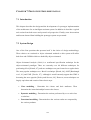
7.1 Introduction
This chapter describes the design and the development of a prototype implementation
of the architecture for an intelligent assistant system. In addition it describes a typical
tool session from both a user and system level perspective. Finally, some observations
and lessons learned from building the prototype system are presented.
7.2 System Design
One of the first questions that presents itself is the choice of design methodology.
These choices are restricted to object orientated methods as this system will utilise
both Java and CORBA which are both fully object orientated.
Object Orientated Analysis (OOA) is a semiformal specification technique for the
object-orientated paradigm. There are currently over 40 different techniques for
performing OOA [Schach, 97], and new techniques are put forward on a regular basis.
The most popular techniques are: Booch’s technique [Booch, 94], OMT [Rumbaugh
et al., 91] and UML [Fowler, 97] - although it would currently appear that UML is
becoming the more popular [Pooley and Stevens, 99]. However, most techniques are
largely equivalent and consist of three basic steps:
•
Class modelling - Determine the classes and their attributes. Then
determine the interrelationships between the classes.
•
Dynamic modelling - Determine the actions performed by or to each class
or subclass.
•
Functional modelling - Determine how the various results are computed by
the various products.
102
The choice of which particular method of OOA to employ for a given project is
usually arbitrary and linked to the experience or preference of the system designer, or
dictated by outside influences. With this in mind, OMT was chosen as the OOA
method for the design of the prototype system.
For the sake of clarity, all OMT class diagrams in this thesis are represented as ‘class
only’, and as such, no attributes and operations appear in the class diagrams.
7.2.1 Design Approach
The proposed architecture can be viewed as containing three major components: User
Interface, Kernel and Agents. This architectural division allowed for an allocation of
design and implementation tasks among the three developer partners of the P3 project,
with the Agent components being the sole responsibility of this researcher.
The use of CORBA imposes a sequence on the design activity. Firstly, each
component in the system should be defined as either a client or a server (in the
CORBA sense) and subsequently the appropriate IDL interfaces between them
defined. These IDL interfaces define the services (methods) provided by each
component (client or server) and the data structures that are transferred between them.
7.2.2 Client-Server Components
Although CORBA uses the terms Client and Server, this does not mean that CORBA
systems have a traditional client-server architecture where a set of clients use a single
server. Instead, the objects in one server may use the objects in other servers. For
example, a client may invoke an object in a server, and that object may invoke others
in order to fulfill the client’s request. This can be achieved using the callback
mechanism which reverses the roles, allowing servers to call a remote object, thus
acting as a client for the duration of that call. This mechanism is often used by a server
to get the attention of a client or another server.
103
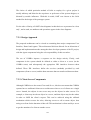
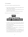
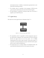
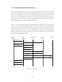
From a CORBA perspective, the proposed architecture has four major components as
illustrated in figure 7.1, which may be classified as either clients or servers:
User Interface
(Client)
CORBA
callback
(server acting
as client)
Standard Client
Server call
CORBA
callback
(server acting
as client)
System Kernel
(Server)
Standard Server
to Server call
Agent Controller
(Server)
Standard
Server to
Server call
Agent Library
(Server)
Figure 7.1 - Client-Server Structure
•
User Interface - Is the only true client in the classical sense. It appears as
the ‘front end’ of the system and will always reside on the client machine,
i.e. users desktop. It only invokes methods on System Kernel objects.
However, the System Kernel may invoke methods on the User Interface
(callbacks), if it requires its attention.
•
System Kernel - As Acts as a server to the User Interface as it provides a
number of services for it, for example, management activities associated
with storing data. In addition, the System Kernel views the Agent Controller
as a server, as it will request certain services from it such as “give me some
advice for this situation”.
•
Agent Controller - Provides services to the System Kernel and as such acts
as a server to it. However, the Agent Controller requires certain services
from the System Kernel (such as data retrieval) for which it will perform a
callback, thus using the System Kernel as a client for the duration of the call.
•
Agent Library - Performs services on behalf of the Agent Controller and as
such views it as a client. For example, the Agent Controller would request
the Agent Library to extract a particular agent for execution.
104
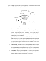
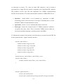
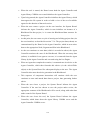
These four CORBA components have several possible implementation configurations
in terms of which component(s) may be installed on which host machine. There are
three typical configurations envisaged, as illustrated in figures 7.2 to 7.4.
1. Desktop configuration - Where all components are installed on a single
machine, say a typical end user desktop PC.
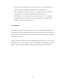
2. Network configuration - Where the User Interface is installed on the
desktop and all other components are on the network server machine.
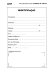
3. Intranet configuration - A variation of a standard network configuration,
with the Agent Library being hosted by the corporate Intranet server and
therefore a central knowledge base available to a wider corporate user group.
Desktop PC
User Interface, System Kernel,
Agent Controller and Agent Library
Figure 7.2 - Desktop Configuration
Desktop PC
Network server
User Interface
System Kernel,
Agent Controller
and Agent Library
CORBA access over Local Area Network
Figure 7.3 - Network Configuration
Desktop PC
Network server
User Interface
System Kernel and
Agent Controller
CORBA access over Local/Wide Area Network
Corporate Intranet
server
Agent Library
Figure 7.4 - Intranet Configuration
105
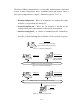
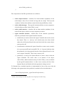
7.2.3 Component Interfaces
As can seen from figure 7.1 there are three IDL component interfaces which have to
be specified, as follows: The User Interface - System Kernel interface (figure 7.5)
shows the User Interface sending either token values or advice requests to the System
Kernel, and the System Kernel sending advice objects or details on the project.
Token values
Advice requests
User
Interface
Advice objects
System
Kernel
Project structure
Token objects
Figure 7.5 - User Interface - System Kernel Interface
The System Kernel - Agent Controller interface (figure 7.6) shows the three main
types of information communicated between the two components - information or
values of tokens, advice requests advice and the advice itself.
Token information
and values
System
Kernel
Advice requests
Agent
Controller
Advice objecs
Figure 7.6 - System Kernel - Agent Controller Interface
The Agent Controller - Agent Library interface (figure 7.7) shows the Agent Library
sending information on agents dependent tokens to the Agent Controller and servicing
requests for agents to be extracted by returning a handle to an agent.
Token dependency
Agent
Controller
Agent extraction
Agent
Library
Agent handle
Figure 7.7 - Agent Controller - Agent Library Interface
106
7.2.4 User Interface
The User Interface components are organised into three main areas:
•
The main window of the application, which deals with the display issues and
CORBA communication initialization.
•
The scenario window, which displays a project and allows the user to create
scenarios based on a project situation.
•
Dialog boxes which display information and allow the user to enter data.
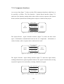
The main classes in the User Interface are illustrated in figure 7.8:
MainFrame
ScenarioManager
DialogManager
GUICallbackImplementation
Figure 7.8 - Overview of User Interface Classes
•
The MainFrame manages all the GUI components (images, windows and
other resources) and initialises CORBA communications between the User
Interface and the System Kernel.
•
The ScenarioManager is used to display the scenario windows and control
all actions associated with it.
•
The DialogManager acts as a generic manager for all dialog boxes and
manages all actions associated with them.
•
The GUICallbackImplementation provides the implementation to the
proxies for the System Kernel callbacks. It runs in a thread and listens to
events coming from the System Kernel. A typical usage would be the
System Kernel indicating the arrival of some advice from an agent.
107
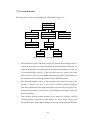
7.2.5 System Kernel
The main classes of the System Kernel are illustrated in figure 7.9:
RootObject
TokenDictionary
ProjectWorkspace
TokenDetails
GUICallback
Scenario
Stage
Advice
Figure 7.9 - Overview of System Kernel Classes
•
The RootObject is the controlling class of the System Kernel and provides a
central storage and access point for different ProjectWorkspace objects. Its
main functionality is concerned with the creation and maintenance of the list
of ProjectWorkspace objects. It also provides access to some of the data
files and is also used to pass CORBA information from the User Interface to
the System Kernel concerning hostnames and callback functions.
•
The ProjectWorkspace object is the central storage object for data in the
package. It allows the user to access the scenarios (work breakdown
structures) and therefore the stages and tokens associated with a project. The
principal functionality of this object is the loading and storing of data for
this Java package.
•
The Scenario objects contain pointers to the stages of a project and the
associated advice generated by the agents for those stages. Any given
ProjectWorkspace may contain multiple scenarios which represent different
108
work breakdown structures or views of a project. This allows the user to
examine a project from different perspectives.
•
The Stage object is used to store the elements of the lifecycle (i.e. the
different activities such as requirements,
specification,
etc.)
and
characteristics connected to a particular part of the lifecycle.
•
The Advice object is used to convey the agent generated advice information
to the User Interface component.
•
The GUICallback object implements the callback features of CORBA which
allow the server (ie. System Kernel) to use part of the functionality of a
client (user Interface).
•
The TokenDictionary groups different TokenDetails objects for display,
where these groupings correspond to different classifications of tokens.
•
The TokenDetails object stores the static information for each token.
Examples of this type of information would be a question that would be
asked (to get a token value) or an explanation (of a tokens meaning). Other
information such as bounds, data types and enumerated lists are stored.
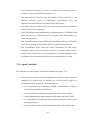
7.2.6 Agent Controller
The main classes of the Agent Controller are illustrated in figure 7.10:
•
The Supervisor object is the main controlling object in the Agent Controller
component. It ensures that all requests are serviced and all advice is
forwarded to the System Kernel. Its main tasks are:
•
It is responsible for initialising CORBA communications with the
System Kernel and the Agent Library.
•
It is responsible for creating new threads of control for new agents.
•
It must maintain these agent threads and time them out after a period.
•
It is responsible for acquiring both the status and values of tokens from
the System Kernel.
•
It is responsible for the creation and maintenance of the AdviceTable.
109
•
It must ensure all advice generated by agents is placed in the
AdviceTable and the System Kernel is notified.
•
It manages the creation of the Blackboard.
Supervisor
InferenceEngines
JessParser
AdviceTable
Advice
Project
Blackboard
Node
ReteCompiler
Slot
Scenario
Segment
Figure 7.10 - Overview of Agent Controller Classes
•
The Project object implements the core functionality of the Agent Controller
and is linked to a single project. It does not have to concern itself with
Kernel communications as this is managed by the Agent Supervisor object.
•
The AdviceTable is responsible for storing all items of advice (i.e. Advice
objects) which are generated by agents. Essentially this object contains a
vector of Advice objects and the methods necessary to maintain the vector.
•
The Advice objects are responsible for storing the actual advice itself.
•
The Blackboard object is responsible for the control of the Blackboard
structure. It must ensure that all relevant data is kept up to date. The object
structure of the Blackboard is the same as described in section 7.3.6.
•
The InferenceEngine is a generic object used to control the execution of an
agent. It is responsible for the interrogation the agent to be executed and
passing it to the appropriate inference engine, along with the actual token
110
and related data values. In addition, it communicates generated advice to the
AdviceTable via the Project object.
•
The JessParser object is responsible for the integration of JESS into the
system. It prepares and interprets data sent to/from the ReteCompiler.
•
The ReteCompiler is responsible executing an agents rules. This object is
supplied as part of the JESS system.
7.2.7 Agent Library
The main classes of the Agent Library are illustrated in figure 7.11:
AgentLibrary
Agents
Figure 7.11 - Overview of Agent Library Classes
•
The AgentLibrary object is responsible for all the management aspects of
the Agent Library component of the system and for the direct interaction
between the agents and the rest of the system, via its CORBA
communications link with the Agent Controller. Upon system startup it is
responsible for passing information to the Agent Controller about the agents,
which is used to construct the Blackboard.
•
The Agents object acts as a storage container for information (tokens, rule
scripts and head information) about each of the agents in the system.
111
7.3 Systen Implementation
The following sections will present a discussion on the implementation of the
prototype system. Firstly the development tools used will be presented, followed by an
example of the IDL interfaces and CORBA client-server setup procedures. This is
followed by a discussion on the implementation of the main system component and
the knowledge base.
7.3.1 Development Tools
The development platform used was a standard Windows NT PC connected via a
LAN to several Netware and UNIX servers. For the development of the system, three
main tools were required: a Java compiler, a Java CORBA ORB and a suitable
development environment.
There are currently several vendors of Java CORBA ORBs in the marketplace, but at
the time of the design phase there were only two main Java CORBA ORBs available:
Iona’s OrbixWeb and Visigenic’s VisiBroker. For the purposes of this research, both
of the ORBs provided the necessary features for the development of the prototype.
OrbixWeb was selected as the implementation ORB primarily because Iona
technology are the recognised world leader in CORBA technology and also because of
this researchers previous research connections with the organisation.
The compiler chosen was Sun’s JDK (initially version 1.1.2) because of the problems
associated with developing CORBA components which needed 100% pure Java, thus
(at that point in time) ruling out compilers supplied by vendors such as Microsoft
[Hunt, 98]. This was used in conjunction with the JBuilder environment which
provided a graphical editing and debugging tool only, not a compiler.
7.3.2 IDL Interfaces
112
As discussed in section 7.2.3, there are three IDL interfaces, each of which is
represented in a single IDL file which is compiled by the OrbixWeb IDL compiler.
This produces several Java files that implement the CORBA communications
facilities for the interface. The main elements that constitute a CORBA IDL file are:
•
Interfaces - which define a set of methods (or ‘operations’ in OMG
terminology) that a client can invoke on an object. Essentially this is a class
definition without an implementation section.
•
Operations - denote a service (method) that clients can invoke.
•
Data types - denote the accepted values of CORBA parameters, attributes,
exceptions and return values. These are named CORBA objects which are
used across multiple languages, operating systems and ORBs.
To illustrate the contents of an interface, the following is an extract from the IDL file
for the System Kernel - Agent Controller interface.
interface AdviceObject {
readonly attribute long projectID;
readonly attribute long scenarioID;
readonly attribute long agentID;
readonly attribute long adviceID;
readonly attribute string advice;
};
typedef sequence<AdviceObject>AdviceTable_vector;
interface AdviceTable {
readonly attribute AdviceTable_vector AdviceTable;
};
interface AgentController {
oneway void startSession();
oneway void createScenario(in long projectID, in long scenarioID);
113
AdviceTable getAdvice();
};
The components of the IDL specification are as follows:
•
Advice object interface - describes five data members (attributes) of the
AdviceObject class, four of which are long and one string4. The keyword
‘readonly’ indicates the attributes cannot be directly modified by a client.
•
Advice table datatype - This typedef statement defines an array (sequence)
of AdviceObjects called ‘AdviceTable_vector’.
•
Advice table interface - describes the one data member (attribute) of the
AdviceTable object, which is an array (sequence) as above.
•
Agent controller interface - defines three of the methods (operations)
which are performed in the AgentController interface.
•
startSession() is used to instruct the Agent Controller that a tool session
has started. This is a ‘oneway’ call, which means the client which
makes the call (System Kernel) does not block while the remote object
processes the call.
•
createScenario() instructs the Agent Controller to create a new scenario
for a given projectID and scenarioID. The ‘in’ keyword indicates that
the parameters are being passed from the client (System Kernel) to the
server (Agent Controller). This is also a oneway call.
•
getAdvice() is used by the System Kernel to retrieve advice from the
Agent Controller. The return value is an instance of the object
AdviceTable, which contains an array of AdviceTable_vector as defined
by the typedef statement above. As this is not a oneway call, the client
(System Kernel) will block while this operation is being serviced.
To illustrate how a method (interface) is implemented in Java on the server side, the
following code segment shows the getAdvice() method call as described above.
class ACImpl implements _AgentControllerOperations {
4
In IDL, a Java int maps to an IDL long and a Java string maps to an IDL string.
114
public AdviceTable getAdvice() {
AdviceTable adviceTableRef = null;
adviceTableRef = new _tie_AdviceTable(adviceTable);
return adviceTableRef;
}
}
This method call is defined in the ACImp class which implements the
_AgentControllerOperations - a class generated by the IDL compiler, which
implements the AgentController interface as described in the IDL file. This
‘implements’ approach to interface implementation is standard when developing Java
based CORBA systems.
The getAdvice() method itself contains three steps:
1. Create a new reference variable adviceTableRef of type AdviceTable (as
defined in the AdviceTable interface in the IDL file) and assign it to null.
2. Assign the reference variable to the previously created adviceTable variable
by way of the _tie_AdviceTable() method (which was generated by the IDL
compiler).
3. Finally return the instance of the AdviceTable reference.
To illustrate how the above method (interface) is called on the client side, the
following code segment shows how the System Kernel uses the getAdvice() method:.
AdviceTable adviceTableRef = null;
adviceTableRef = ACproxy.getAdvice();
This call involves two steps:
1. Create a new reference variable adviceTableRef of type AdviceTable (as
defined in the AdviceTable interface in the IDL file) and assign it to null.
115
2. Assign this reference to the results of the getAdvice() call. This call is made
by prefixing the call with a reference name (proxy name) for the server
(Agent Controller) on which the method call resides. This reference name
(‘ACproxy’) is assigned when the CORBA server is first launched and a
bind takes place. This notion of a bind is explained in the following section.
7.3.3 Client-Server Components
In order to service client requests on a particular interface, the server which provides
the service must inform the ORB that it is available. This is done by initializing the
ORB (using the ORB.init() method), creating an instance of the interfaces
implementation class and informing the ORB that the server is available (using the
_CORBA.Orbix.impl_is_ready() method). The Java code segment below shows how
the Agent Controller server would perform this.
public class AgentControllerServer {
public static void main(String args[]) {
ORB.init();
AgentController ACImpl = null;
ACImpl = new _tie_AC(new ACImpl ());
_CORBA.Orbix.impl_is_ready("AC_Server"),
}
}
In order for a client to use the services of a server, it must first establish a link to the
server. The following Java code segment shows how the System Kernel would
establish a CORBA communications link to the Agent Controller.
public class SystemKernel {
public static void main(String args[]) {
ORB.init();
String hostname;
AgentController ACproxy = null;
116
hostname = new String(_CORBA.Orbix.myHost());
ACproxy = ACHelper.bind("AC_Server", hostname);
}
}
The above procedure involves the following steps:
1. Initialize the ORB using the ORB.init() method.
2. Create a reference variable (proxy) to act as a pointer to the server.
3. Identify the host on which the server program resides. In this case it is
assumed to be the same as the client program.
4. Bind to the server using the ACHelper.bind() method and specifying the
name of the server and the host on which it resides.
Finally, all servers must register their presence to the CORBA ORB via an
implementation repository, which acts as a database of mappings from server names
to Java bytecodes. This allows the CORBA ORB to find the actual Java bytecode for a
given implementation when a client binds to it. In OrbixWeb this is done by using the
‘putit’ utility with the parameters of server name and location.
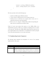
7.3.4 Implementing System Components
The following tables summarise the development of a series of five prototype
implementations of the system:
Heading
Description
Prototype
First prototype - codename ‘Cavan’.
Purpose
At the time of implementation there was almost no commercial JavaCORBA development being conducted, therefore an architectural
proof was developed to highlight any technical issues associated with
117
using Java and CORBA.
Functionality
A skeleton of the four main CORBA components which operated by
sending a series of messages to a DOS window indicating the calls.
Contained no other functionality or graphical user interface.
Tools used
OrbixWeb 2.0, JDK 1.1.2 and JBuilder 1.0 as editing environment.
Table 7.1 - Prototype One
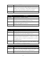
Heading
Description
Prototype
Second prototype - codename ‘Noumea’.
Purpose
To implement the basic functionality of the system and put in place
mechanisms for the entering and management of data.
Functionality
A small number of basic JESS agents developed. This version also
included a crude graphical user interface.
Tools used
OrbixWeb 2.0, JDK 1.1.4 and JBuilder 1.0 as editing environment.
Table 7.2 - Prototype Two
Heading
Description
Prototype
Third prototype - codename ‘Salonika’.
Purpose
To create the first functioning version of the system to be
demonstrated to users as part of the validation exercise.
Functionality
An enhanced System Kernel, including file storage and scenarios. A
complete GUI and the implementation of a small set of ‘realistic’
JESS agents which were capable of providing advice on scenarios
developed by the user.
Tools used
OrbixWeb 3.0 (which contained the official OMG mapping), JDK
1.1.5 and JBuilder 2.0 as editing environment.
Table 7.3 - Prototype Three
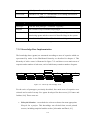
Heading
Description
Prototype
Fourth prototype - codename ‘Burgundy’.
Purpose
To create a more fully functioning version of the system. This
version was the main subject of the user validation process.
Functionality
Additional number of fully functioning agents and the optimisation
118
of the System Kernel, including the removal of a number of bugs.
Tools used
OrbixWeb 3.0, JDK 1.1.7 and JBuilder 2.0 as editing environment.
Table 7.4 - Prototype Four
Heading
Description
Prototype
Fifth and final prototype - codename ‘Tipperary’.
Purpose
The creation of a pre-commercial prototype.
Functionality
Two main enhancements: the addition of a larger set of fully
functioning agents and the removal of identified bugs in the system.
Tools used
OrbixWeb 3.0, JDK 1.1.7 and JBuilder 2.0 as editing environment.
Table 7.5 - Prototype Five
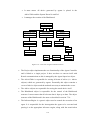
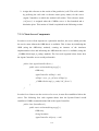
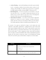
7.3.5 Knowledge Base Implementation
The knowledge base (agents) are structured according to areas of expertise which are
represented by nodes in the Blackboard hierarchy as described in chapter 6. This
hierarchy of advice areas is illustrated in figure 7.12 and shows seven main areas of
expertise and a number of sub-areas, each of which may contain a number of agents.
Advice areas
Analysis & planning
Estimation
Activity planning
Measurement
Resource allocation
Risk management
Selecting lifecycle
Selecting method
Identifying activities
Metrics
Identfying needs
Standards
Analysing estimates
Scheduling
Analysis
Scheduling resources
Analysis
Team skill mix
Mitigation
Project re-planning
Identification
Monitoring
Figure 7.12 - Hierarchy of Knowledge Areas
For the series of prototypes previously described, four main areas of expertise were
selected and a total of twenty five agents developed for those areas [O’Connor and
Jenkins, 99a]. These areas are:
•
Lifecycle Selection - covered advice on how to choose the most appropriate
lifecycle for a project. This knowledge was elicited from several printed
sources, including empirical studies such as [Alexander and Davis, 91].
119
•
Activity Planning - assists with identifying activities that a project should
involve, developing a schedule for the activities and the resources it will
consume. This knowledge was elicited from several sources, in particular
the SPIRE handbook [Sanders, 98] from ESPRIT / ESSI project 23873.
•
Risk Management - A series of risk agents were developed to cover the
four main areas of risk - cost, schedule, technical and operation risk. The
primary source for these agents was the US Air Force risk management
taxonomy [USAF, 88], as used in the RISKMAN2 project.
•
Measurement and Metrics - covers advice on the selection of appropriate
measures for a project to be used as indicators of product and process
quality. The advice for this area was mainly provided by one of the partners
in the AMI (Application of Metrics in Industry) project [Pulford et al., 96].
The structure of an agent was described in chapter 6 and contains three main
components: Agent Header (identification / configuration data), Agent Tokens (data
about a project) and Rules (JESS rule script). Table 7.6 shows the three sections for an
agent which specialises in requirements characteristics of the activity planning area.
Here four tokens (table 7.7) may be assigned one of three values which correspond to
advice text (table 7.8) and associated SPICE (ISO 15504) recommended best practices
[Sanders, 98]. These tables are taken from volume 2 of the Handbook and Training
Guide [P3, 99] of the P3 project, which contains a complete set of decision tables.
Heading
Agent Header
Description
; 1,1,2
; Agent zero for Characteristics Requirements
; Version 1.1a
; 12,13,14,16
Agent Tokens
(deftemplate Agent0
(slot _12) (slot _13) (slot _14) (slot _16))
120
(Agent0
(_12 ?tk1) (_13 ?tk2) (_14 ?tk3) (_16 ?tk4))
Partial section of
; token 14
JESS rule script for
(if (= ?tk3 3)
tokens 14 and 16
then (bind ?c "C.R.5 C.C.1 C.C.3 " crlf))
(if (= ?tk3 2)
then (bind ?c "C.R.5 C.C.3 C.C.1 " crlf))
(if (= ?tk3 1)
then (bind ?c "C.P.3 " crlf))
(if (= ?tk3 0)
then (bind ?c "" crlf))
; token 16
(if (or (= ?tk4 3)(= ?tk4 2))
then (bind ?d "C.R.1 C.R.5 C.R.6 " crlf)
else (bind ?d "" crlf))
Table 7.6 - Example Agent
Token
High
Medium
C.R.1
Low
C.R.Complexity
C.R.1
None
C.R.Volatility
C.R.2, C.R.3, C.R.4 C.R.2, C.R.3, C.R.4 None
C.R.Inflexibility
C.R.5
C.R.5
C.R.Application
None
C.R.1, C.R.5, C.R.6 C.R.1, C.R.5, C.R.6
C.R.5
Table 7.7 - Token Values
No.
C.R.1
Advice
Recommended Activities
Allocate extra time for requirements IA1, IIA2, IIA4, IIA6, IIA7, IIB1,
analysis.
C.R.2
You
need
configuration
IIB2, IIB3, IIB7, IIB8, IIC5
an
extremely
management
good IIIB1-IIIB9
system,
especially for change control.
C.R.3
Prioritise your development so the parts IA1, IIA2, IIA4, IIA6, IIA7, IIB1,
121
with most volatility have a longer IIB2, IIB3, IIB7, IIB8, IIC5
analysis
period
and
the
latest
development slot.
C.R.4
Establish a good verification process.
IIID1-IIID4
C.R.5
Make sure you get the requirements IF1-IF6
right the first time with a strong
requirements gathering process.
C.R.6
Try to prototype as much as possible.
Table 7.8 - Advice Text
7.3.6 Knowledge Base Evolution
As described in section 6.3.7, the agent-orientated framework allows for a dynamic
agent population, as the Agent Library builds a view of the set of available agents at
the start of a session. This allows agents to be added or removed from the system by
the addition or deletion of their corresponding agent file, thus providing for a
dynamically updateable knowledge base, where knowledge (agents) may be added,
revised or removed without impact on the rest of the system. Thus the knowledge base
may grow over time to take account of new expertise or techniques in software project
planning.
During the implementation phase of the prototypes a total of twenty five agents were
developed, as follows:
•
Prototype 1 - contained five agents for test purposes only. They did not
contain any real knowledge, rather they were used for testing component
communication and data structures.
•
Prototype 2 - contained nine basic JESS agents, four of which were in the
area of lifecycle selection and five in risk management.
•
Prototype 3 - contained fifteen agents, which included an addition of six
activity planning agents.
122
•
Prototype 4 - contained twenty agents, which included an addition of three
metrics and measurement agents and two further risk management agents.
•
Prototype 5 - contained twenty five agents, which included an addition of
two more metrics and measurement agents and two additional activity
planning agents.
As described in section 7.3.5, each agent contains three main components: Agent
Header (identification / configuration data), Agent Tokens (data about a project) and
Rules (JESS rule script). The process of constructing the prototype systems agents (as
above) consisted of the translation of the decision tables from volume 2 of the P3
Handbook and Training Guide into the set of token value tables (figure 7.7) and the
corresponding advice text tables (figure 7.8). These tables were subject to verification
by the original author of the decision tables prior to the implementation of a set of
JESS rules to implement the decision table. These rule scripts were then tested using
the JESS interpreter and corrections made as appropriate. Finally the agent file was
added to the Agent Library directory on the file system, where it would be
automatically detected upon tool invocation. The process of creating a new agent (i.e.
translating a decision model to JESS rule script) while not trivial, is a reasonably
straightforward process, which can be completed within a short period of time.
7.4 System Usage
The following two sections illustrate an example of a typical user session with the
prototype system and provide an explanation of both the user level and system
(component) level interaction.
7.4.1 Example User Session
This section illustrates an example of a typical user session with the prototype system
and provides a narrative detailing the user level interaction with the system
components.
123
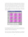
A typical session is started by the user selecting a previous project or starting a new
project. In the later case, they select New Project Workspace from the menu which
displays the ‘Project Model Selection’ screen (figure 7.13). This screen allows the
user to select the type of project model they wish to use, where the choice is
represented by a grid showing project size versus complexity. For each model, a
description is displayed in a text area at the bottom of the screen. When the user
selects a model and clicks on the New button, a project workspace is created, along
with its first scenario.
Figure 7.13 - Project Model Selection Screen
After selecting the appropriate APM, the system sets up the relevant default values for
the project and then opens the main scenario window. The user now enters the second
typical stage of a session, that of defining the project.
There are five main areas or domains in which information can be specified and
choices made. Each domain is represented by a separate panel (screen), which can be
124
selected either from the main menu or by using the toolbar buttons provided.
Depending on the APM selected, many of these choices will be already selected with
initial default values (any of which can be changed if required). The five domain
panels are:
•
Characteristics panel - the basic characteristics of the project such as
requirements, customer, business drivers and project environment.
•
Project panel - covers matters connected with the nature of the project
itself, such as resources, estimation, schedule and cost.
•
Quality panel - asks questions concerned with quality systems in the
organisation, quality characteristics relevant to a planned product (or
specified by the customer) and includes sub-domains such as organisation,
product and customer.
•
Plan panel - presents a list of standard stages making up the life cycle, and
asks the user to specify some plan details about each. Each of these stages
can then be further divided, if required, into sub-stages to allow for a finer
degree of management of the project.
•
Metrics panel - gives some recommendations for a minimum set of metrics
for a project.
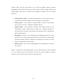
Figure 7.14 shows the ‘Project Plan Panel’ screen, with the project’s tasks organised
in a tree structure on the left hand side. Here the user has the ability to increase,
decrease, re-order, add or remove tasks for a given project.
125
Figure 7.14 - Project Plan Panel Screen
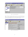
Figure 7.15 shows a ‘question and answer session’ for a given scenario. The user
chooses the most appropriate answer for their situation and thus communicates
specific information about the project to the tool (and also to the agents).
Figure 7.15 - Scenario Window Screen
126
Figure 7.16 shows the Scenario Manager window, which allows users select a
scenario for further examination or delete an existing scenario. In addition, some
information on the selected scenario is displayed in the bottom section of the screen.
Figure 7.16 - Scenario Manager Screen
As the user continues to refine the project plan, the project parameters (tokens) are
being continuously analysed by the agents. When advice is available, it is indicated on
the bottom right of the main screen (see figure 7.17).
Figure 7.17 - Advice Counter
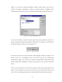
In order to view advice, the user selects the Advice Manager window (see figure 7.18)
which in this case is displaying some of the advice text for the requirements
characteristics agent above. This text is formatted using HTML and displayed using
the Sun Swing GUI components. The user may choose to store, print or delete the
advice.
The user may then choose to amend some aspect(s) of the project plan based on the
advice received, which in turn may cause more advice to be generated. Thus the user
enters a loop of refining project plans and exploring different project plan scenarios.
127
Figure 7.18 - Advice Manager window
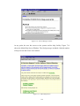
At any point, the user has access to the systems on-line help facility. Figure 7.19
shows the Main Help Screen Window. The final prototype included a limited number
of help screens and a basic user manual.
Figure 7.19 - Main Help Screen
128
7.4.2 Example Component Interaction
This section illustrates the system level interaction between components which take
place during a typical user session, as described in the previous section. In particular it
focuses on the messages passed between the Agent Controller, Blackboard, Agent
Library and Agents themselves, from the starting of the tool and a project through to
the subsequent closure of both a project and the tool.
Figure 7.20 is an event trace diagram which illustrates an abstract view of the message
passing between system components. Due to the complex nature and large number of
messages passed between the various components and their associated objects, this
diagram illustrates the message passing at a high-level abstract view and not at the
level of object method invocation.
System
Kernel
Agent
Controller
Blackboard
Agent
Library
Agent
Tool started
Library setup
Project started
Blackboard setup
Project data
Write data
Monitor status
Extract agent
Agent reference
Execute agent
Advice
Advice
Advice
Project close
Tool close
Figure 7.20 - Event Trace
129
•
When the tool is started, the Kernel starts both the Agent Controller and
Agent Library CORBA servers and initialises the Agent Controller.
•
Upon being started, the Agent Controller initialises the Agent Library, which
interrogates the file system in order to build a view of the set of available
agents for the duration of that tool session.
•
When the user creates a project via the user interface, the System Kernel
informs the Agent Controller, which in turn initialises an instance of a
Blackboard for that project, ie. it creates the Blackboard data structure for
that project.
•
At this point, the user enters a cycle of entering and refining project data (via
the user interface) as described in section 7.3.6. The project data (tokens) are
communicated by the Kernel to the Agent Controller, which in turn writes
them to the appropriate Node, Segment and Slot in the Blackboard.
•
As the user continues to enter data (which is recorded as above) the Agent
Controller monitors the state of the Blackboard. When the necessary data
(tokens) is available for an agent to execute, it is extracted from the Agent
Library by the Agent Controller and executed using the Jess Engine.
•
When an Agent has completed execution, it communicates its advice to the
Agent Controller, which then forwards this advice (via the AdviceTable
object) to the System Kernel for subsequent display to the user. The Agent
Controller also notes the advice generation in the Blackboard.
•
This sequence of component interactions will continue while the user
continues to enter and amend data about a project, thus generating further
advice.
•
When the user closes a project, the System Kernel informs the Agent
Controller. If the user has chosen to save the project under review, the
appropriate contents of the Blackboard will be saved, along with other data
under control of the System Kernel.
•
When the user closes the tool, the System Kernel informs the Agent
Controller, which shuts down the Agent Library CORBA server and the
Agent Controller CORBA server.
130
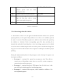
7.5 Prototype Development Observations
This section will present some technical observations and lessons learned from the
construction of the prototype system [O’Connor and Jenkins, 99b]:
•
The CORBA imposed design sequence (defining IDL interfaces first)
proved to be advantageous as it removed the possibility of ambiguity in the
interpretation of the interfaces by the system developers, which was
especially useful given the distributed nature of the development.
•
Configuration management of IDL is particularly important as any change to
an IDL definition must be replicated on both client and server sides.
•
Not all Java structures are supported by the IDL mappings. For example;
arrays of an undefined size are permissible in Java, but no mappings exist
for such structures in IDL.
•
Subsequent to the release of the official OMG IDL-Java mapping standard,
all interfaces had to be revised to conform to the standard, which required
changes to IDL and server initialisation routines.
•
One of the main programming issues was the additional complexity in code
due to CORBA. For example; synchronisation issues in relation to nononeway IDL operations which complicated the introduction of Java threads.
•
Debugging CORBA-Java programs is more difficult because standard debug
tools are not capable of tracing a remote method call across an ORB.
At this point it is also worth noting some of the positive points in relation to the
development of the prototype system:
•
Java and CORBA work well together. This in the most part is due to Java’s
built-in multi-threading, garbage collection and error management which
makes it easier to write robust network objects. Also, Java’s object model
compliments CORBA’s as they both use the concept of interfaces to
separate an object’s definition from its implementation.
131
•
For the reasons stated above, Java has proven to be a faster platform in
which to develop CORBA based applications by comparison to C++.
•
The incorporation of JESS proved to be a technical success in that JESS
components were seamlessly integrated into the prototype system.
•
The addition of new agents into the system proved to be a reasonably
straightforward process, which was achieved without any re-configuration or
alteration to other system components.
7.6 Summary
This chapter contains a description of the issues surrounding the implementation of
the prototype system, including both the design and development of the prototype. In
addition, some observations made and lessons learned from building the prototype
system were presented.
Chapter 8 presents the field of research methodology and provides a review of a the
approaches that are used within the field of computing and information systems.
Further, it has described the approach which shaped the design user trials process.
132