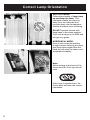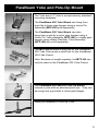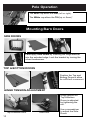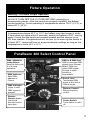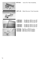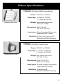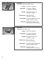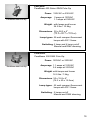
1
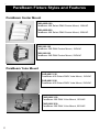
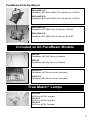
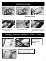
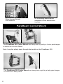
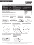
Operation Manual
ParaBeam ® 400/200 Series
ParaBeam 400 Center Mount
ParaBeam 400 Pole-Op
Part No. 3100026 Rev D
01-04-2010
x
ParaBeam Fixture Styles and Features
ParaBeam Center Mount
PAR-400S-120
ParaBeam 400 Select DMX Center Mount, 120VAC
PAR-400S-230
ParaBeam 400 Select DMX Center Mount, 230VAC
PAR-200-120
ParaBeam 200 DMX Center Mount, 120VAC
PAR-200-230
ParaBeam 200 DMX Center Mount, 230VAC
ParaBeam Yoke Mount
PAR-400Y-120
ParaBeam 400 Select DMX Yoke Mount, 120VAC
PAR-400Y-230
ParaBeam 400 Select DMX Yoke Mount, 230VAC
PAR-200Y-120
ParaBeam 200 DMX Yoke Mount, 120VAC
PAR-200Y-230
ParaBeam 200 DMX Yoke Mount, 230VAC
2
2
ParaBeam Pole-Op Mount
PAR-400P-120
ParaBeam 400 Select DMX Pole-Op Mount, 120VAC
PAR-400P-230
ParaBeam 400 Select DMX Pole-Op Mount, 230VAC
PAR-200P-120
ParaBeam 200 DMX Pole-Op Mount, 120VAC
PAR-200P-230
ParaBeam 200 DMX Pole-Op Mount, 230VAC
Included w/ All ParaBeam Models
GFR-P4
ParaBeam 400 Gel Frame (Included)
GFR-P2
ParaBeam 200 Gel Frame (Included)
LVR-P4-S
ParaBeam 400 Silver Louver (Included)
LVR-P2-S
ParaBeam 200 Silver Louver (Included)
True Match ® Lamps
55C-K29
55W Kino KF29 Compact
55C-K32
55W Kino KF32 Compact
55C-K55
55W Kino KF55 Compact
3
3
ParaBeam Center Mount Kits
KIT-P4-S120
ParaBeam 400 DMX Kit, 120VAC
KIT-P4-S230
ParaBeam 400 DMX Kit, 230VAC
Kit Contents:
1 ParaBeam 400 DMX Center Mount
1 Lamp Case
1 Ship Case
Dimensions
29.5
x 11 x 29.5"
30
x 12.5
30.5"
(76
(75 x 32
28 x 77.5cm)
75cm)
Weight
61lb (27.5kg)
KIT-P2-120
ParaBeam 200 DMX Kit, 120VAC
KIT-P2-230
ParaBeam 200 DMX Kit, 230VAC
Kit Contents:
1 ParaBeam 200 DMX Center Mount
1 Lamp Case
1 Ship Case
Dimensions
21.5
11.5x x23"
29"
35.5 x 12
(54.6
x 29.2
x 73.6cm)
(90 x 30.5
x 58.5cm)
Weight
45lb (20.3kg)
4
4
Inserting Lamps
Open hinged reflector
door.
Snap lamp pins into
Lamp holder.
Insert lamp end first.
Close reflector door.
To release lamps, press
Red button and lift lamp
out.
Inserting Louvers, Diffusers or Gel Frame
Push tab down
and forward to
lock into open
position.
Insert gel frame and diffuser
(optional accessory) into
channel closest to lamps.
5
5
Silver Louver fits into
front channel.
All 4 retaining tabs must be
extended to lock accessories
in place.
ParaBeam Center Mount
The ParaBeam 400 Center Mount can
hang
from
a grid
a Junior
hanger
hangs
from
a grid
by abyJunior
pipepipe
hanger
mountson
onaaJunior
JuniorStand.
Stand.
or mount
Note: Loop the safety chain through the handle on the ParaBeam 400.
The ParaBeam 200 Center Mount can
hangs
from
a grid
by abybaby
pipepipe
hanger
hang
from
a grid
a baby
hanger
mount on
or mounts
onaababy
babystand.
stand.
6
6
A 180 degree turn is all that is required
to loosen the mount for orientation.
To adjust the tension on the lock lever, pull
handle away from mount. This disengages
the handle from the screw mechanism and
allows the lever to be reoriented. You can
also use a screwdriver to adjust the tension.
Pull back on handle and adjust screw.
Beam Angle Orientation
Vertical beam angle
Horizontal beam angle
7
7
Correct
Lamp Orientation
Orientation
Correct Lamp
VERTICAL MODE:
Follow the principle of lamp base
up and lamp tip down. This
orientation keeps the mercury
away from the cathodes and
provides best color temperature
stability and best color rendering.
DO NOT operate fixtures with
lamp base in the down position.
Color can diverge up to 400K and
will get very green.
HORIZONTAL MODE:
Even in the horizontal position
a slight rotation favoring the lamp
tips (lamp base higher than the
lamp tip) will allow for better color
temperature stability.
Note:
When looking at the back of the
fixture the Kino Flo Logo should
read:
If the Logo is upside down, the
fixture does not have the correct
orientation.
8
8
ParaBeam Yoke and Pole-Op Mount
The Yoke has a ½” hole to accept industry standard
mounting hardware.
The ParaBeam 400 Yoke Mount can hang from
a grid by a junior pipe hanger using a Junior Pin
Assembly (MTP-I80) sold separately.
The ParaBeam 200 Yoke Mount can also
hang from a grid by a junior pipe hanger using a
Junior Pin Yoke Assembly (MTP-I80) or a baby pipe
hanger using a Baby Receiver Yoke Assembly
(MTP-I40) also sold separately.
The MTP-I80 includes a long bolt for the ParaBeam
400 Yoke Fixture and a short bolt for the ParaBeam
200 Yoke Fixture.
Note: Because of weight capacity, the MTP-I40 can
only be used on the ParaBeam 200 Yoke Fixture.
The ParaBeam 400 and 200 Pole-Op Mount
include a yoke with an attached junior pin. They can
be hung from a grid with a Junior pipe hanger.
Junior pin attached to Pole-Op Yoke
9
9
Pole Operation
The Blue cup alters the Pan (left or right).
right.)
The White cup alters the Tilt (up or down.)
down).
Mounting Barn Doors
SIDE DOORS
First apply Side Doors by inserting the hinge bracket
into the extruded edge. Lock the bracket by turning the
silver thumbscrew.
TOP & BOTTOM DOORS
Position the Top and
Bottom Doors to allow
for sufficient movement.
movement.
HINGE TENSION ADJUSTMENT
Hinge tension on
Top & Bottom
Doors is adjusted
by tightening the
nut.
Top & Bottom Door
10
Side Door
Use a screwdriver
to adjust the Side
Doors
10
Fixture Operation
Warning! To Ensure Proper Operation
ALWAYS TURN OFF THE FIXTURE BEFORE connecting or
disconnecting lamps. After the lamps are properly installed, the Ballast
can be turned on. Avoid operating in temperatures above 125°F (51°C) or
below 60°F (15°C).
In temperatures below 60°F or 15°C the ballast may take longer to strike.
If lamp does not strike within 5 seconds, switch the ballast to OFF, and try
again. Check that the lamps are properly seated and the dimmer is up
full, then restrike. If temperatures are too low, try to warm up the fixture to
at least 60°F. Lamps will turn on at preset dimmer settings as long as the
temperature is above 60°F or 15°C.
ParaBeam 400 Select Control Panel
DMX / MANUAL
Lamp Select:
Sets the fixture for
2 or 4 lamp
operation.
DMX Address:
Sets DMX
address of
Fixture.
DMX Indicator:
Lights if valid
DMX signal is
present.
Remote
Dimmer Jack:
Hand held
dimmer control
input jack
DMX-In & DMX-Out:
DMX-in receives DMX
signals from Dimmer
Board. DMX-Out
relays DMX signal
through to other
fixtures or
Instruments.
End of Line:
Terminates DMX
signal at the end of
Fixture series.
Dimmer Control:
Rotary dimming
control
Power Switch:
Turns fixture on and
off.
11
11
Manual Operation
The on-board dimmer dial can manually
dim lamps.
The REMOTE DIM jack enables the
use of a handheld remote control dimmer
(Part # DIM-5, Hand Held Dimmer).
The MANUAL DIM LAMPS switch selects 2 or 4
lamp operation. In the 2 setting the center two lamps
are dimmed. In the 4 setting all four lamps are
dimmed.
Note: All manual controls are disabled as soon as
the DMX cable is applied. For Manual control with
DMX cables plugged in, sett address to”000”.
There is a 5 second delay when switching between
DMX and Manual control.
DMX Operation
DMX Addressing
Prior to hanging any instruments set the
DMX address of each Fixture.
Push the tabs above or below the number window to
set the address. (Valid addresses range from 001 to
512.) The light above the address block will illuminate
if a DMX signal is present.
The DMX DIM CHANNELS feature allows user to
select two sets of lamps for DMX dimming control.
The ParaBeam 400 Select operates on one or two
DMX addresses.
Position 1 requires one DMX address and renders
control of all four lamps on one dimmer channel.
Position 2 requires two DMX addresses to control
4 lamps on two addresses and two dimmer channels.
The 1st address controls the inner two lamps.
The 2nd address controls the outer two lamps.
12
12
Tip: Position 2 allows for a greater degree of control. The board operator
can turn two lamps off (1 f-stop drop in exposure) without shifting the color
temperature.
The ParaBeam 200 operates on one address
per fixture. Two lamps are dimmed on one
dimmer channel.
The END OF LINE switch must be set to
open ( O ) on Fixtures within the DMX chain.
Set to END OF LINE when the Fixture is the
last DMX control device in the chain.
Note: When the last Fixture's DMX Term
is set to “END OF LINE,” it will absorb
all energy in the DMX line, ensuring
DMX signals are transmitted correctly.
If a signal is not terminated, it is called a
“Reflected Wave,” and may create
transmission errors by causing valid
DMX signals to be canceled.
ParaBeam Fixtures can be jumpered
using the IN and OUT ports. As many as
100 Fixtures can be jumpered on one chain
as long as the DMX cable run remains under
1000 feet or 40 x 25ft DMX cables.
Note: When operating Fixtures at great
distances from the dimmer board, it is
recommended to use Opto-Isolators to
provide DMX signal amplification.
NOTE: If a Fixture or Ballast loses its DMX signal it will hold its last DMX
command. For this reason it is important to turn a Fixture or Ballast off using
the DMX commands. For example, if you try to turn off the lights by turning off
the dimmer board the lights will remember their last DMX command and stay on.
The Fixtures or Ballasts require a DMX “Off” or “Black-out” command in order to
turn off.
13
13
Trouble
TroubleShooting
Shooting
LAMPS
LAMPSFAIL
FAILTO
TOLIGHT:
LIGHT:
x x With
Withthe
thepower
powerswitch
switchininthe
theON
ONposition,
position,the
thered
redlight
lightshould
shouldbebeon.
on.If Ifit itisisnot,
not,
Voltage
Voltageisisnot
notpresent.
present.Check
Checkyour
yourpower
powerfeed.
feed.Check
Checkthe
thefuse
fuseononthe
thefixture
fixtureand
and
replace
replaceif ifnecessary
necessary(5(5x x20mm,
20mm,T3.15AH/250V,
T3.15AH/250V,Time
TimeDelay
DelayType)
Type)
x x Replace
Replacelamp
lampororlamps.
lamps.
x x Check
Checkballast
ballastcontact.
contact.Make
Makesure
sureballast
ballastisisproperly
properlyseated;
seated;lock
locktab
tabmust
mustbebe
locked
lockedininplace
place(see
(seechecking
checkingballast
ballastnotes).
notes).
x x After
Afterhaving
havingchecked
checkedthat
thatlamps
lampsand
andballasts
ballastsare
arecorrectly
correctlyseated,
seated,turn
turnoffoffpower
power
totothe
thefixture
fixtureforfor6060seconds
secondsand
andrestart.
restart.
x x Replace
Replaceballast
ballastcard
cardwith
withone
onethat
thatisisknown
knowntotowork.
work.
x x With
WithDMX
DMXcable
cableconnected,
connected,if ifyellow
yellowlight
lightisisoff,
off,there
thereisisnonoDMX
DMXsignal.
signal.
Establish
Establisha avalid
validDMX
DMXsignal.
signal.
x x With
WithDMX
DMXcable
cableplugged
pluggedininand
andyellow
yellowindicator
indicatoron:
on:
1.1. Address
Addressmust
mustbebebetween
between001
001and
and512.
512.Addresses
Addressesabove
above512
512
are
areinvalid.
invalid.
2.2. The
Thedimmer
dimmersetting
settingononthe
thelighting
lightingboard
boardmust
mustbebeininthe
thefull
fullupupmode.
mode.
3.3. The
Thelast
lastfixture
fixturemust
musthave
havethe
theDMX
DMXtermination
terminationswitch
switchset
settoto
END
ENDofofLINE.
LINE.Numerous
Numerousterminated
terminatedfixtures
fixturesonona aDMX
DMXrun
runwill
will
result
resultininDMX
DMXsignal
signalcorruption.
corruption.
CHECKING
CHECKINGBALLAST:
BALLAST:
Pull
Pullout
out3 3white
white
push-pins.
push-pins.
Pushupuplock
locktab
taband
andpull
pull
Remove
Removeend
endcover
coverwith
with Push
outballast
ballastcard.
card.
out
white
whitepush-pins.
push-pins.
The
Theballast
ballastisismounted
mountedtotoa acircuit
circuitboard
boardwith
withend
end
contacts
contactstotoallow
allowforforrapid
rapidballast
ballastreplacement
replacement
without
withoutthe
theuse
useofofadditional
additionaltools.
tools.
Lock
Locktab
tabmust
mustbebelocked
lockedfor
forproper
properballast
ballast
contact.
contact.
Note:
Note:On
OnParaBeam
ParaBeam200
200Yoke
Yokeand
andParaBeam
ParaBeam
200
200Pole-Op,
Pole-Op,the
theYoke
Yokewill
willneed
needtotobeberemoved
removed
totoaccess
accessballasts.
ballasts.
14
14
14
Accessories
Accessories
Accessories
Accessories
BRD-P4…
BRD-P4…
BRD-P4…
ParaBeam
ParaBeam
ParaBeam
400
400
400
Barndoors
Barndoors
Barndoors
(set
(set
(set
of
of4)
of
4)
4)4)
BRD-P4…
ParaBeam
400
Barndoors
(set
of
BRD-P2…
BRD-P2…
BRD-P2…
ParaBeam
ParaBeam
ParaBeam
200
200
200
Barndoors
Barndoors
Barndoors
(set
(set
(set
of
of4)
of
4)
4)4)
BRD-P2…
ParaBeam
200
Barndoors
(set
of
DFS-P4…..ParaBeam
DFS-P4…..ParaBeam
400
400
Diffuser
Diffuser
DFS-P4…..ParaBeam
400
Diffuser
DFS-P4…..ParaBeam
400
Diffuser
DFS-P2…..ParaBeam
DFS-P2…..ParaBeam
200
200
Diffuser
Diffuser
DFS-P2…..ParaBeam
200
Diffuser
DFS-P2…..ParaBeam
200
Diffuser
DIM-5…
DIM-5…
Remote
Remote
Dimmer
Dimmer
DIM-5…
Remote
Dimmer
DIM-5…
Remote
Dimmer
KAS-P41…
KAS-P41…
KAS-P41…
KAS-P41…
ParaBeam
ParaBeam
ParaBeam
ParaBeam
400
400
400
400
Center
Center
Center
Center
Ship
Ship
Ship
Ship
Case
Case
Case
Case
KAS-P21…
KAS-P21…
KAS-P21…
KAS-P21…
ParaBeam
ParaBeam
ParaBeam
ParaBeam
200
200
200
200
Center
Center
Center
Center
Ship
Ship
Ship
Ship
Case
Case
Case
Case
KAS-CL6
KAS-CL6
KAS-CL6
KAS-CL6
6-Lamp
6-Lamp
6-Lamp
6-Lamp
Carry
Carry
Carry
Carry
Case
Case
Case
Case
(55W
(55W
(55W
(55W
Compact)
Compact)
Compact)
Compact)
MTP-LMT
MTP-LMT
MTP-LMT
….
….
….
Kino
Kino
Kino
81
81
81
Lollipop
Lollipop
Lollipop
w/
w/w/
Junior
Junior
Junior
Pin
Pin
Pin
Straight
Straight
Straight
MTP-LMT
….
Kino
81
Lollipop
w/
Junior
Pin
Straight
(for
(for
(for
Center
Center
Center
Mount
Mount
Mount
only)
only)
only)
(for
Center
Mount
only)
15
15
15
15
15
MTP-I80.… Junior Pin Yoke Assembly
LVR-P445.… ParaBeam 400 Louver 45°
LVR-P460…. ParaBeam 400 Louver 60°
LVR-P490….. ParaBeam 400 Louver 90°
LVR-P245.… ParaBeam 200 Louver 45°
LVR-P260…. ParaBeam 200 Louver 60°
LVR-P290….. ParaBeam 200 Louver 90°
MTP-I40…..Baby Receiver Yoke Assembly
7010004…ParaBeam 400 Yoke Assembly
7010005…ParaBeam 200 Yoke Assembly
LVR-P445.… ParaBeam 400 Louver 45°
7010006…ParaBeam
400 400
Pole-Op
LVR-P460…. ParaBeam
Louver 60°
Yoke
Assembly
LVR-P490….. ParaBeam 400 Louver 90°
7010007…ParaBeam
200 200
Pole-Op
LVR-P245.… ParaBeam
Louver 45°
Yoke
Assembly
LVR-P260…. ParaBeam 200 Louver 60°
LVR-P290….. ParaBeam 200 Louver 90°
7010004…ParaBeam
400 Yoke
Assembly
55C-K29…55W Kino KF29
Compact
55C-K32…55W Kino KF32 Compact
7010005…ParaBeam
200 Yoke
Assembly
55C-K55…55W Kino KF55
Compact
7010006…ParaBeam 400 Pole-Op
Yoke Assembly
16
7010007…ParaBeam 200 Pole-Op
Yoke Assembly
55C-K29…55W Kino KF29 Compact
55C-K32…55W Kino KF32 Compact
55C-K55…55W Kino KF55 Compact
16
16
Fixture Specifications
PAR-400S
ParaBeam 400 Select DMX Center Mount
Power: 120VAC or 230VAC
Amperage: 2 amps at 120VAC
1.1 amps at 230VAC
ParaBeam
ParaBeam
400400S
Center
Weight: with lamps and louver
24.2 lbs / 10.9kg
Dimensions: 24.5 x 24 x 8”
(62 x 61 x 20.5cm)
Lamp types: 55 watt compact fluorescent
lamps with 2G11 base
Switching: 2 lamp and 4 lamp on/off
Manual and DMX dimming
PAR-200
ParaBeam 200 DMX Center Mount
Power: 120VAC or 230VAC
Amperage: 1.1 amps at 120VAC
0.6 amps at 230VAC
ParaBeam
200
ParaBeam
200 Center
Weight: with lamps and louver
16.5 lbs / 7.4kg
Dimensions: 24.5 x 13.5 x 7.5”
(62 x 34.5 x 19cm)
Lamp types: 55 watt compact fluorescent
lamps with 2G11 base
Switching: 2 lamps on/off
Manual and DMX dimming
17
17
PAR-400Y
ParaBeam 400 Select DMX Yoke
Power: 120VAC or 230VAC
ParaBeam
400Y
ParaBeam
400
Yoke
Amperage: 2 amps at 120VAC
1.1 amps at 230VAC
Weight: with lamps and louver
24.2 lbs / 10.9kg
Dimensions: 29.5 x 26.8 x 6”
(75 x 68 x 15.2cm)
Lamp types: 55 watt compact fluorescent
lamps with 2G11 base
Switching: 2 lamp and 4 lamp on/off
Manual and DMX dimming
PAR-200Y
ParaBeam 200 DMX Yoke
Power: 120VAC or 230VAC
ParaBeam
200
Yoke
ParaBeam
200Y
Amperage: 1.1 amps at 120VAC
0.6 amps at 230VAC
Weight: with lamps and louver
16.5 lbs / 7.4kg
Dimensions: 29.5 x 15.8 x 6”
(75 x 40 x 15.2cm)
Lamp types: 55 watt compact fluorescent
lamps with 2G11 base
Switching: 2 lamps on/off
Manual and DMX dimming
18
18
PAR-400P
ParaBeam 400 Select DMX Pole-Op
Power: 120VAC or 230VAC
ParaBeam
ParaBeam
400400P
Pole-Op
Amperage: 2 amps at 120VAC
1.1 amps at 230VAC
Weight: with lamps and louver
24.2 lbs / 10.9kg
Dimensions: 30 x 26.3 x 6”
(76.2 x 66.7 x 15.2cm)
Lamp types: 55 watt compact fluorescent
lamps with 2G11 base
Switching: 2 lamp and 4 lamp on/off
Manual and DMX dimming
PAR-200P
ParaBeam 200 DMX Pole-Op
Power: 120VAC or 230VAC
ParaBeam
200200P
Pole-Op
ParaBeam
Amperage: 1.1 amps at 120VAC
0.6 amps at 230VAC
Weight: with lamps and louver
16.5 lbs / 7.4kg
Dimensions: 30 x 15.8 x 6”
(76.2 x 40 x 15.2cm)
Lamp types: 55 watt compact fluorescent
lamps with 2G11 base
Switching: 2 lamps on/off
Manual and DMX dimming
19
19
For latest Warranty information and Certifications,
see Kino Flo website at www.kinoflo.com.
Environmental: Disposal of Old Electrical & Electronic Equipment.
This symbol on the product or on its packaging indicates that this product
shall not be treated as household waste. This product is made of recyclable
materials and should be disposed of in accordance with local and state
regulations.
Kino Flo, Inc. 2840 N. Hollywood Way, Burbank, CA 91505, USA
Tel: 818 767-6528 website: www.kinoflo.com
16