1
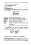
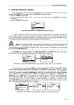
SV 31
Acoustic calibrator
User’s manual
Warsaw, August, 2010
SVANTEK Sp. z o.o.
Pl. Inwalidów 3/62
01-514 Warsaw, Poland
Phone/fax: (+22) 839-00-31
e-mail: [email protected]
NIP 527-010-52-72
Production Department & Service
ul. Chodakowska 26/32. II p.
03-816 Warszawa
Phone/fax: (+22) 871-05-36
Phone/fax: (+22) 871-04-69
e-mail: [email protected]
SV 31 USER MANUAL.
Contents
1.
Introduction...........................................................................................................1
1.1. Calibration .................................................................................................... 1
1.2. Accuracy of calibration ................................................................................. 1
1.3. Classification of sound level meters and acoustic calibrators....................... 2
2. Acoustic calibrator SV 31 .....................................................................................2
2.1. General description ...................................................................................... 2
2.2. Usage of the calibrator ................................................................................. 4
2.2.1. Automatic calibration............................................................................. 4
2.2.2. Button functions .................................................................................... 4
2.2.3. Indicators .............................................................................................. 5
2.3. Replacing the battery ................................................................................... 6
3. SV 31 Datasheet ..................................................................................................8
1. Introduction
1.1. Calibration
One of the fundamental questions that are most frequently asked while taking
a measurement is whether its result is accurate. Proceeding with a measurement
without having a positive answer to this question may result in obtaining data of
no practical use and wasting our time. However, we may easily obtain the answer
by performing a calibration of the sound level meter together with the microphone
and its preamplifier. Calibration of the measurement device may be done in two
ways: by comparing the calibrated device with a reference device of known
parameters; or using a template of the measured quantity to perform a reference
measurement. Acoustic devices are usually calibrated in the latter fashion with
so-called, acoustic calibrators. Acoustic calibrator is a device, which produces
acoustic pressure of defined level and frequency. In other words, such calibrator is a
template of acoustic pressure. With help of such a template we can check the
accuracy of the measurements performed with the sound level meter and/or calibrate
it if the error occurs.
1.2. Accuracy of calibration
Each measurement performed with any measurement device is burdened with
an error. Result obtained from such measurement is only an estimate of the real
value of the measured quantity. It is impossible to remove the error completely,
as the values given by the meter are discrete whereas the measured quantity is
of continuous nature. Hence, the purpose of calibration is to limit this inevitable error
to a certain acceptable level. Maximum absolute value of the error of measurement
(or of the generated signal in the case of the calibrator) is called the tolerance and is
strictly defined by the standards for the given type of device.
A sound level meter is calibrated correctly if and only if the measurement error
is within the range of tolerance defined by the standards for the meter of a given
class.
1
SV 31 USER MANUAL
.
1.3. Classification of sound level meters and acoustic calibrators
The acoustic calibrators (see IEC 60942: 2003) and the sound level meters
(see IEC 61672: 2002) are divided into classes and types respectively, according to
their accuracy. Type 0 imposes the strictest requirements on the device. Devices of
this class are ranked as the most precise. Each of the following types (1, 2 and 3)
allows for the wider range of tolerance (see Table 1).
Table 1. Tolerance values for the given types of acoustic devices excluding maximum expanded
uncertainty of measurement (f = 1 kHz)
Class / Type
Sound level meter, [dB]
Acoustic calibrator, [dB]
LS
0.10
1
0.7
0.25
2
1.0
0.40
As indicated in Table 1, an acoustic calibrator has significantly lower tolerance
than a sound level meter of the same class. Intuitively, we understand, that
the calibrator, as a reference for acoustic pressure must be more precise than
a measurement device.
Taking acoustic measurements according to norms and standards imposes
the requirement of calibrating the measurement channel before each measurement
or measurement session and very often as well after the measurement for result
verification purposes.
2. Acoustic calibrator SV 31
2.1. General description
The SV 31 acoustic calibrator is a small, portable one-range Type 1 device
(sound source), see Picture 1. Powered by two LR03/AAA batteries, it contains
a loudspeaker producing acoustic pressure, reference microphone for monitoring
generated level, pressure and temperature sensors for measurements
of atmospheric conditions and a microprocessor system controlling the operation
of the calibrator. Sinusoidal waveform of 1 kHz frequency is digitally generated
and feeds the loudspeaker. Sampled signal from the reference microphone indicates
the level of currently generated signal in a feedback loop. On the basis
of information about the level of the signal, actual values of pressure and
temperature, microprocessor adjusts amplification of the loudspeaker signal in order
to produce appropriate sound pressure level in the calibrator’s chamber.
Due to the feedback regulation loop the SV 31 calibrator does not require
adjusting and operates in a wide range of temperatures and humidity (see SV 31
Datasheet).
2
SV 31 USER MANUAL.
Picture 1. Acoustic calibrator SV 31
The SV 31 is designed for calibration of sound level meters with ½” and ¼”
microphones. Picture 2 shows the calibration procedure of Type 1 sound level meter
SVAN 945A with a ½” microphone.
Picture 2. Calibration of the SVAN 945A sound level meter with a ½” measurement microphone
Notice: For calibration of a meter with a ¼” microphone the SA 30
reduction adapter must be applied.
Picture 3 presents the calibration procedure of Type 2 sound level meter SVAN 943B
3
SV 31 USER MANUAL
.
with a ¼” microphone.
Picture 3. Calibration of the SVAN 943B sound level meter with a ¼” measurement microphone
2.2. Usage of the calibrator
2.2.1. Automatic calibration
The SV 31 calibrator is equipped with an optical system which detects the
presence of a microphone in the calibrator’s chamber. That allows the calibrator to be
switched on automatically, when it is placed on the microphone and to be switched
off when it is dismounted. For this reason, usage of the SV 31 calibrator is as simple
as putting it on the microphone, performing the calibration and taking it off the
microphone.
2.2.2. Button functions
The SV 31 calibrator is equipped with a multifunctional button for controlling
operation of the device. There are two functions of the button (see Table 2). First of
all the button is used to turn ON and OFF the device. In this case the button pushing
has immediate effect.
Either when the SV 31 is ON or OFF pressing the button over 10 seconds and
releasing it will cause full reset of the system. Normally this function is not necessary.
It has been implemented in the case of inappropriate operation of the calibrator
caused by external (EM radiation, subnormal atmospheric conditions, etc) or internal
(inappropriate system reset as a result of battery replacement, etc) factors.
4
SV 31 USER MANUAL.
The operation time of the calibrator with a microphone put inside its chamber
is limited to 3-5 minutes. This functionality was added in order to save the battery,
e.g. when the calibrator is accidentally left with the microphone inside.
Notice: Leaving the SA 30 reduction adapter in the chamber of the
calibrator is equivalent with the state of the microphone being left inside.
Hence, the calibrator will switch off automatically after 3-5 minutes from
the moment the adapter is put inside the calibrator
Table 2. Functional description of the calibrator’s button
Button press
Short, less than 10 sec.
Over 10 sec.
Function description
Turn on/off the device
Full reset of the system
2.2.3. Indicators
There are two LED to indicate the state of the SV 31 calibrator. One of them is
titled “114 dB” and shows the state of the generated level.
After the calibrator is put on the microphone or switched on, acoustic pressure
inside the calibrator’s chamber is adjusted to the desired level. During that process
“114 dB” diode blinks with a frequency of approx. 2 Hz.
Device is ready when this diode burns with continuous light.
Notice: Calibration should not be performed until the “114 dB” diode is
burning with continuous light.
The diode called “LOW. BAT.” presents the batteries status. The batteries
voltages under 2.1 V cause “LOW. BAT.” blinking with approximately 2 Hz frequency.
It is recommended to not use the SV 31 calibrator in this state as the generated level
may differ from the declared values.
Notice: Replace the batteries, when diode “LOW. BAT.” blinks.
5
SV 31 USER MANUAL
.
Picture 4. The top view of the SV 31 calibrator with one burning diode
2.3. Replacing the battery
The battery should be replaced as follows:
a) remove the rubber cover on the button and diodes’
side
b) holding the cover unscrew four fixing screws with your
fingers
c) take off the cover and remove discharged batteries
6
SV 31 USER MANUAL.
d) put new batteries in place of the discharged ones with
polarization as indicated on the printed board and
calibrator’s case
e) put on the cover so that the diodes fit the
corresponding holes in it
f) holding the cover with one hand fasten the fixing
screws
g) put on the rubber cover
7
SV 31 USER MANUAL
.
3. SV 31 Datasheet
Output signal
Sound Pressure Level (SPL):
114 dB, with respect to 20 µPa in reference
conditions
Accuracy:
IEC 60942: 2003 standard, Type 1
SPL Accuracy:
±0.3 dB
Frequency accuracy:
±0.02 %
Total Harmonic Distortions (THD): < 0.75 %
Reference conditions
Temperature:
23 °C
Atmospheric pressure:
101.3 kPa
Humidity:
30-80 % RH
Effective microphone load volume:250 mm3, microphone type: 4134, SN: 1591010
General data
Effective load volume sensitivity:
Level stabilization time:
Microphone dimensions:
Storage temperature range:
CE classification:
Working conditions
Temperature range:
Atmospheric pressure range:
Humidity range:
0.00027 dB / mm3
typical 7 sec., max. 10 sec.
½” and ¼” with reduction adapter SA 30
-25 °C do + 70 °C
EMC: EN 50081-1, EN 50082-1
Safety: EN 61010-1: 2001
from –10 °C to +50 °C
from 65 kPa to 108 kPa
up to 90 % RH
Environmental conditions influence (typical)
Temperature coefficient:
±5·10-3 dB/°C
Pressure coefficient:
±1·10-4 dB/hPa
Humidity coefficient:
±1.25·10-3 dB/%
Power supply
Battery type:
Continuous operation time:
Standby mode: approx.
Minimal working voltage:
two LR03 (IEC)/AAA (ANSI) alkaline batteries
30 hours
2 years
2.1 V
Dimensions and weight
Weight:
Dimensions:
305 g with batteries
65 x 65 x 70 mm
8