1
PROMECH III
USER'S MANUAL
This package provides facilities for the description and analysis of many three-dimensional and
planar mechanisms. A kinematic model of the mechanism can be drawn, and the velocity and
acceleration of any part of it can be determined throughout its cycle of movement. Loadings on
joints caused by the accelerations within the mechanism can also be calculated.
The package is written throughout in Fortran 77, and is readily available to interested parties.
A.L. Johnson
Cambridge University Engineering Department,
Trumpington Street,
Cambridge, U.K.
May, 2000
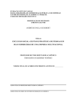
Figure 1: Typical 3-D Mechanism (Hooke's Joint)
Section I - Description of the package
The package consists of a family of Fortran subroutines designed to calculate the velocity and
acceleration and inertia forces of elements in spatial mechanisms. By writing a programme which
calls these subroutines the user is able to describe the topology of a mechanism, to set it in motion,
and by interrogation to find the subsequent position, velocity, and acceleration of any part of it.
With this information the user can proceed to calculate inertia stresses and other data within the
main programme. Incorporation of the calculation and interrogation sequence into a program loop
permits the mechanism to be analysed throughout its entire cycle.
The mechanisms analysed consist of solid bodies which may be connected to other bodies by
means of cylindrical shafts which fit into cylindical holes, pockets, or slots. Any properlyconstrained mechanism driven by shafts which move axially (i.e. rams) and/or which rotate about
their axis can be analysed.
A typical mechanism is shown in Figure 1. The sequence of specifications would be as follows:
Describe bodies:
(Body 1 is the fixed frame)
There are two deep cylindrical holes in the fixed frame
Body 2 is a fork
Body 3 is a cross
Body 4 is a second fork
Describe constraints:
Body 2 is fitted into one of the fixed holes, with axial and rotational constraint
Body 2 is fitted onto the cross, in two places
Body 4 is also fitted onto the cross, in two places
Body 4 is fitted to the second fixed hole, but with no axial or rotational constraint.
Describe motion:
The pin on body 1 in the fixed hole has a given angular velocity with respect to the body, which
causes the body to rotate relative to the frame.
2
The positions, velocities, and accelerations of all the bodies and specified points can now be found,
using various 'interrogation' routines. Following a call to a subroutine which ‘advances the clock’,
the behaviour of the mechanism can be recalculated at another point in its cycle.
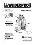
Each new body which is created is given a 'type', as shown in Fig. 2. As can be seen, these types
have various numbers of 'tags' (shafts or holes) which can be joined to appropriate tags on other
bodies.
Figure 2: Standard body types
3
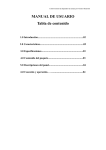
In addition to its standard tags, any body can be given further tags, of the types shown in Fig. 3.
When a joint is made, the two tags are quoted, together with information about whether rotation
about, and movement along, the shaft axis is permitted. This is equivalent to giving the shaft a circlip
and/or a keyway, as shown in Fig.3. This allows for 16 different kinds of joints, each of which
imposes a certain number of constraints on the overall mechanism, as shown in the cells in Fig. 3.
For the mechanism to be analysed, the total number of constaints must be six times the number of
bodies (apart from the fixed frame) which have been created.
SHAFTS: ALL TYPE 0
Groove for Circlip
Keyway
HOLE TYPES
1
1
2
2
3
2
2
3
3
4
3
2
3
3
4
4
4
5
5
6
Figure 3: Standard tag and joint types, showing the
number of constraints introduced by each joint
4
Section II - Method of operation
The subroutines can be called by any program and are accessed by including the Promech III
Library when the program is linked or loaded. The method by which this is done is implementationdependent.
External references created by the user, such as the names of subroutines and Fortran common
areas, should not begin with the letters PM
A complete program to analyze the mechanism in Figure 1 is given in Section IV. The program
starts with any interactive driving instructions which the user wishes to insert, and continues with a
description of the mechanism and then the calculation of a complete cycle at two-degree intervals of
rotation of the driving crank. Full details of the subroutines are given in Section III below, where the
subroutines are placed in alphabetical order. They can, however, be usefully grouped as follows:
Initialization:
CALL MECHINIT
initiates data stores ready for a new mechanism
Description:
CALL BODY
CALL ADDTAG
CALL BODROT
CALL BODMOV
CALL JOINT
specifies a new body
adds a 'tag' (pin, round hole or slot) to a body
rotates a body into position for assembly
moves a body into position for assembly
specifies a joint between two bodies
CALL ROTATE
CALL MOVE
gives a pin rotary motion about its axis
gives a pin linear motion along its axis
Forces &c.
CALL BODMAS
CALL ADDMAS
CALL FORCE
specifies a body's mass and inertias
gives a body additional mass and inertias
applies a force to a tag
Set time:
CALL TSET
sets the clock
Interrogation:
CALL PTASK
CALL BDASK
CALL FCASK
finds a point’s position, velocity, & acceleration
finds a body’s position, velocity, & acceleration
finds the forces and couples acting on a tag
Graphics:
CALL SEEFIT
CALL VIEWROT
CALL DRAWMECH
CALL GRCLOSE
sets a flag to animate the assembly process
sets the viewing direction
draws the mechanism in its current position
closes down graphics after use
Resetting:
CALL RESET
resets the mechanism to its initial position
Advanced use:
CALL GRSET
sets up the graphics environment if you need to use it
before Promech does
overrides Promech’s graphics controls
Set or amend
motion:
CALL GRUSER
5
There are a few rules about the order in which these subroutines should be called. The following
flowchart shows the normal calling sequences:
INITIALISATION
DESCRIPTION
SET MOTION
(SET TIME)
ALTER TIME,
AMEND MOTION
OR RESET
KINEMATIC INTERROGATION / DRAWING
SET / AMEND FORCES
FORCE INTERROGATION
Section III - The subroutines
A full specification of the subroutines is given in alphahabetic order in this section. Arguments
beginning with I are integer and others are real, in accordance with Fortran defaults. Those
beginning with V are vectors, and should be given dimensions of (3) in the calling program. All
angles are in radians unless otherwise stated. Other units are at the user’s discretion, but must be
consistent – for instance, forces will only be returned in Newtons if lengths are quoted in metres,
masses in kilograms and time in seconds.
A mechanism may currently consist of up to 20 bodies, each of which may contain up to 10 tags:
these limits can be increased if required.
CALL ADDTAG(ITYPE,IBOD,XP,YP,ZP,X1,Y1,Z1,X2,Y2,Z2)
adds a tag of type ITYPE to body IBOD at the initial position
(XP,YP,ZP) in the body's local co-ordinates, with axis direction
(X1,Y1,Z1) and initial reference direction (X2,Y2,Z2) (see Fig. 4). All
'tags' (shafts or holes) on bodies are given unique numbers starting from
1, though the first few are usually predefined according to the type of
body (see Fig. 2). If IBOD=1 a fixed tag is created, since body 1 is the
reference frame. If the given reference direction is not perpendicular to
the axis direction, the component which is perpendicular will be used
instead. Body IBOD must exist when ADDTAG is called.
CALL ADDMAS(IBOD,RM,GX,GY,GZ,XX,YY,ZZ,XY,YZ,ZX)
gives body IB an additional mass of RM with its centre of gravity at
(GX,GY,GZ) in local body co-ordinates, and with moments and
products of inertia Ixx, Iyy, Izz, Ixy, Iyz and Izx.
6
CALL BDASK(IBOD,VV,VA)
returns the current angular velocity vector VV, and angular acceleration
vector VA of body IBOD.
CALL BODMAS(IBOD,RM,GX,GY,GZ,XX,YY,ZZ,XY,YZ,ZX)
specifies the mass (RM) of body IB, its centre of gravity (GX,GY,GZ)
in local body co-ordinates, and the moments and products of inertia
Ixx, Iyy, Izz, Ixy, Iyz and Izx.
CALL BODMOV(IBOD,X,Y,Z)
Moves the body IBOD through the vector (X,Y,Z) in the fixed
reference frame. Bodies should be in approximately the correct
position before the mechanism is interrogated.
H1
H2
S2
H3
S
H
S3
S1
Figure 4: Definition vectors for shafts and holes
CALL BODROT(IBOD,IAX,ANG)
rotates body IBOD through an angle ANG radians about the axis IAX
of the fixed reference frame (1=X, 2=Y, 3=Z). The position of the
body's origin does not change. Bodies should be in approximately the
correct position before the mechanism is interrogated.
CALL BODY(ITYPE,S1,S2,S3)
specifies a new body of type ITYPE (see Fig. 2) with dimensions S1
S2 and S3 (where appropriate). If ITYPE=0, the body is a tagless
(and featureless) blob. The body is initially positioned with its origin and
axes coincident with those of the fixed reference frame. Bodies are
given unique numbers starting from 1, which is the fixed reference
frame.
CALL DRAWMECH
produces a schematic drawing of the mechanism in its current position
(see Fig. 5).
CALL FORCE(ITAG,IBOD,FX,FY,FZ,CX,CY,CZ)
applies a force (FX,FY,FZ) and couple (CX,CY,CZ) to tag ITAG on
body IBOD. This force remains acting on the tag until it is altered, or
set to zero.
7
CALL FCASK(ITAG,IBOD,VF,VC)
returns the force (VF) plus the couple (VC) acting on the tag ITAG of
body IBOD, in local body co-ordinates. The line of action of the force
is through the tag location quoted in ADDTAG. The force and couple
include forces from any other body jointed to this tag, and any external
forces specified by FORCE.
CALL GRCLOSE
closes down the graphics environment, and restores the normal
behaviour of the screen or window. On a Windows 9x/NT machine, it
may also be necessary to type Alt-Enter from the keyboard to restore
the window size.
CALL GRSET
sets up the Promech graphics environment. Promech does this
automatically when it needs to draw something, but this subroutine is
available in case your program needs to use the graphics environment
before Promech does.
CALL GRUSER
prevents Promech from choosing the scale of the drawing, and from
clearing the drawing area before drawing a picture. This subroutine is
only used in advanced graphics applications, e.g. a split-screen display
(see Section V). If you call this routine, you must ensure that the onscreen plotting area is suitable for drawing the mechanism, and must
clear the screen if necessary between successive drawings.
CALL JOINT(ITAG1,IBOD1,ITAG2,IBOD2,IALOK,ITLOK)
specifies a joint between tag ITAG1 on body IBOD1 and tag ITAG2
on body IBOD2. One of the tags must be a pin and the other a hole,
pocket, or slot; and the tags and bodies must exist when the subroutine
is called. If IALOK ? 0, the shaft is given an axial constraint (i.e. a
circlip) which keeps its position coincident with the baseplane of the
hole or slot; and if ITLOK ? 0, it is given a rotational constraint (i.e. a
woodruff key) which keeps its reference direction in the plane of the
hole's reference direction and axis. The bodies and tags must already
have been specified when JOINT is called.
CALL MECHINIT
initializes the data area or clears all accumulated data about an existing
mechanism, permitting the main program to define a completely new
one without restarting. The reference frame (body 1) is set up, with no
tags.
CALL MOVE(ITAG,IBOD,S,DS,D2S)
specifies that tag ITAG on body IBOD is to have its reference point
moved through S along its axis with velocity DS and acceleration D2S.
The tag must be a shaft.
8
CALL NOSET
inhibits the default automatic scaling by DRAWMECH when the first
picture is requested. This is sometimes necessary, e.g. if only part of
the graphics area is to be used for the kinematic picture, as in the
sample program.
CALL PTASK(ITAG,IBOD,VP,VV,VA)
returns the current position (VP), velocity (VV) and acceleration (VA)
of the tag ITAG on body IBOD.
CALL RESET
resets the mechanism and clock to the condition they were in when the
mechanism was first drawn or interrogated.
CALL ROTATE(ITAG,IBOD,A,DA,D2A)
specifies that tag ITAG on body IBOD is to have its reference direction
turned through angle A (in radians) with respect to its initial direction
(anticlockwise when the tag's axis is pointing at you) with angular
velocity DA and angular acceleration D2A. The tag must be a shaft.
CALL SEEFIT
causes a sequence of pictures to be drawn as the mechanism is
assembled. This is particularly helpful if you are getting problems with
convergence on initial assembly.
CALL TSET(T)
advances the clock to time T. The positions and velocities of all points
set by MOVPNT and the angles and angular velocities of all bodies set
by ROTATE are altered by an amount corresponding to their quoted
velocities and accelerations over the elapsed time interval since the last
call to TSET, or since (T=0) if this is the first call to TSET since
MECHINIT.
CALL VIEWROT(IAX,ANG)
rotates the mechanism reference system through an angle ANG (in
degrees) about the axis IAX of a fixed viewing frame (1=X, 2=Y,
3=Z) to determine direction the mechanism is viewed from when
MECHDRAW is called. Initially the axes of the mechanism reference
system are aligned with those of the viewing frame, with X pointing to
the right, Y upwards, and Z towards the user.
9
Section IV - A Simple Example
A straightforward sample user program is shown below. It describes the mechanism shown in Fig.
1, following the sequence specified in Section I. The output is an animated version of the left half of
Fig. 5, showing the joint operating.
C SAMPLE CODE FOR UNIVERSAL JOINT
C GET ANGLE FOR JOINT, AND INITIALISE PROMECH
WRITE(*,*)'Joint angle?'
READ(*,*)A
C=COS(A/57.298)
S=SIN(A/57.298)
CALL MECHINIT
C TAGS FOR BODY 1(FRAME)
CALL ADDTAG(4,1, -12.,0.,0.,
-1.,0.,0.,
CALL ADDTAG(4,1, 12.*C,12.*S,0., C,S,0.,
C BODY 2 (1ST FORK)
CALL BODY(3,4.,6.,6.)
C BODY 3 (CROSS)
CALL BODY(4,5.,5.,0.)
C BODY 4 (2ND FORK)
CALL BODY(3,4.,6.,6.)
C JOINTS BETWEEN BODIES
CALL JOINT(1,1,1,2,1,1)
CALL JOINT(2,1,1,4,0,0)
CALL JOINT(2,2,1,3,0,0)
CALL JOINT(3,2,2,3,0,0)
CALL JOINT(2,4,3,3,0,0)
CALL JOINT(3,4,4,3,0,0)
C POSITION THE BODIES
CALL BODROT(4,1,1.57)
CALL BODROT(4,3,A/57.+3.14)
CALL BODMOV(2,-12.,0.,0.)
CALL BODMOV(4,12.*C,12.*S,0.)
C SET UP VIEWING DIRECTION
CALL VIEWROT(3,-60.)
CALL VIEWROT(1,-60.)
C INPUT VELOCITY
CALL ROTATE(1,2,0.,1.,0.)
C LOOP FOR ONE REVOLUTION OF THE JOINT
DO 20 I=0,179
CALL TSET(FLOAT(I)*3.14159/90.)
C DRAW PICTURE OF MECHANISM
20
CALL DRAWMECH
CALL GRCLOSE
STOP
END
10
0.,1.,0.)
S,-C,0.)
Section V - An Advanced Example
A more advanced version of the program from Section IV is shown below. It illustrates how
Promech can be used in conjunction with the system’s native graphics routines to produce more
advanced displays. Statements in lower case are calls to a proprietary DOS graphics package
(details on request), and not to Promech routines.
C SAMPLE CODE FOR UNIVERSAL JOINT
C Implementation-specific graphics calls shown in lower case
C GET ANGLE FOR JOINT, AND INITIALISE PROMECH
DIMENSION VV(3),VA(3)
WRITE(*,*)'Joint angle?'
READ(*,*)A
C=COS(A/57.2958)
S=SIN(A/57.2958)
CALL MECHINIT
C TAGS FOR BODY 1(FRAME)
CALL ADDTAG(4,1, -12.,0.,0.,
-1.,0.,0., 0.,1.,0.)
CALL ADDTAG(4,1, 12.*C,12.*S,0., C,S,0.,
S,-C,0.)
C BODY 2 (1ST FORK)
CALL BODY(3,4.,6.,6.)
C BODY 3 (CROSS)
CALL BODY(4,5.,5.,0.)
C BODY 4 (2ND FORK)
CALL BODY(3,4.,6.,6.)
C JOINTS BETWEEN BODIES
CALL JOINT(1,1,1,2,1,1)
CALL JOINT(2,1,1,4,0,0)
CALL JOINT(2,2,1,3,0,0)
CALL JOINT(3,2,2,3,0,0)
CALL JOINT(2,4,3,3,0,0)
CALL JOINT(3,4,4,3,0,0)
C POSITION THE BODIES
CALL BODROT(4,1,1.57)
CALL BODROT(4,3,A/57.+3.14)
CALL BODMOV(2,-12.,0.,0.)
CALL BODMOV(4,12.*C,12.*S,0.)
C SET UP VIEWING DIRECTION
CALL VIEWROT(3,-60.)
CALL VIEWROT(1,-60.)
C INPUT VELOCITY
CALL ROTATE(1,2,0.,1.,0.)
C INITIALISE GRAPHICS & DRAW AXES FOR VELOCITY GRAPH
CALL GRSET
call write('Press any key to stop',21)
call pnt(.525,0.)
call lin(.525,.6)
call colour(2)
call pnt(.525,.25)
call lin(.975,.25)
call uscl(8.,8.)
call orig(.2,.3)
C INHIBIT AUTOMATIC SCALING OF DRAWING BY PROMECH
11
CALL GRUSER
ICOLOUR=12
C ALTER COLOUR FOR VELOCITY PLOT AT START OF EACH LOOP
10
ICOLOUR=16-ICOLOUR
C LOOP FOR ONE REVOLUTION OF THE JOINT
DO 20 I=0,179
CALL TSET(FLOAT(I)*3.14159/90.)
C FIND ANGULAR VELOCITY OF OUTPUT (BODY 4)
CALL BDASK(4,VV,VA)
R=SQRT(VV(1)**2+VV(2)**2+VV(3)**2)
C DRAW SECTION OF LINE FROM PREVIOUS INSTANT TO PRESENT INSTANT
call colour(icolour)
call pnt(float(i-1)/400+.525,rold/4.)
if(i.gt.0)call lin(float(i)/400.+.525,r/4.)
ROLD=R
C CLEAR LEFT-HAND HALF OF SCREEN
call i10hd(256*6,0,256*4+1,256*23+39)
C DRAW PICTURE OF MECHANISM AND TEST FOR USER INTERRUPT
CALL DRAWMECH
call testkey(ib)
20
IF(IB.NE.0)THEN
CALL GRCLOSE
STOP
ENDIF
C START ANOTHER LOOP
GO TO 10
END
Figure 5: Screen display generated by program in Section V
12
Section VI - Error messages
If any rules are broken, an error message is generated by the subroutine which detects the fault.
This consists of the subroutine's name together with a short diagnostic, and the program then usually
halts. A typical error message might be 'BODY: OUT OF SEQUENCE', which would tell the user
that one of the calls to subroutine BODY had not been made in the order shown in Section II.
The full list of diagnostics is as follows:
BAD ALIGNMENT
The two parts of a joint are so far out of alignment that it is
not clear which way they should fit, e.g. the axis of a pin is
perpendicular to the axis of the hole it is to fit into.
CONSTRAINTS OR BODY POSITIONS BADLY SPECIFIED
The mechanism may be overconstrained in one area and
underconstrained in another, or the initial positions of the
bodies may have caused the assembly process to 'stall' (e.g.
a pin may be lying exactly perpendicular to the hole it fits
into).
FEMALE TAG
ROTATE and MOVE can only operate on pins.
INVALID AXIS
The axis for BODROT must lie in the range 1 - 3.
INVALID BODY
A body number quoted in the call to the subroutine is greater
than the number of bodies so far defined, or less than 1. In
the case of subroutine ROTATE, body no. 1 is also invalid,
as the reference frame can't rotate.
INVALID TAG
A tag number quoted in the call to the subroutine is greater
than the number of tags so far defined on the body, or less
than 1.
INVALID TAG TYPE
A call to ADDTAG has been made with an illegal value of
ITYPE.
NO CONVERGENCE ON ASSEMBLY
The mechanism cannot be assembled - either because the
parts do not fit, or because the approximate angles of the
bodies give an appropriate starting point for the assembly
process.
This can happen on initial assembly, or
subsequently if the time steps are too large.
OUT OF SEQUENCE
The subroutine has not been called in the sequence
suggested in Section II.
13
PARALLEL VECTORS
The two direction vectors for a tag need not be exactly
perpendicular, but must not be parallel.
TAG ALREADY IN USE
A tag can only be used for one joint. Two coincident tags
can however be specified on a body, if required: e.g. if two
bearings are fitted on a shaft.
TWO MALE/FEMALE TAGS
A joint must always consist of a pin, and some type of hole
or slot.
TOO MANY BODIES
The current limit is 20, including the fixed frame.
TOO FEW / MANY CONSTRAINTS
The number of constraints placed on the mechanism by the
joints (see Fig. 3) must be equal to 6 times the number of
bodies in the mechanism, not including the fixed frame.
TOO MANY FORCES
The current limit is 100
TOO MANY JOINTS
The current limit is 100
TOO MANY TAGS ON A BODY The current limit is 10
ZERO LENGTH VECTOR
The direction vectors quoted to ADDTAG cannot be zero.
14