1
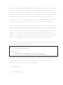
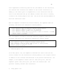
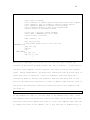
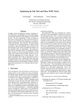
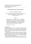
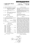
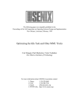
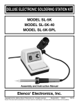
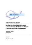
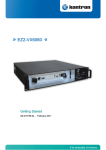
ABSS v2.0: a SPARC Simulator
Dwight Sunada
David Glasco
Michael Flynn
Technical Report: CSL-TR-98-755
April 1998
ABSS v2.0: a SPARC Simulator
Dwight Sunada
David Glasco
Michael Flynn
Technical Report: CSL-TR-98-755
April 1998
Computer Systems Laboratory
Departments of Electrical Engineering and Computer Science
Stanford University
William Gates Building, A-408
Stanford, California 94305-9040
<e-mail: [email protected]>
Abstract
This paper describes various aspects of the augmentation-based SPARC simulator
(ABSS). We discuss (1) the problems that we solved in porting AugMINT to the SPARC
platform to create ABSS, (2) the major sections of ABSS, and (3) the limitations of
ABSS.
Key Words and Phrases: AugMINT, multi-processor, simulator, SPARC
Copyright (c) 1998
Dwight Sunada, David Glasco, Michael Flynn
1
I.
Introduction
A.
Background
The multi-processor simulator (MPS) simulates the operation of a multiprocessor computer and helps us to predict its performance.
1 of the 2 broad categories shown in Figure 1.
A MPS falls into
A trace-driven MPS reads a
file containing the memory references generated by an application; the MPS
uses these references to drive the simulation of the memory system.
By
contrast, a program-driven MPS interleaves the execution of the application
and the simulation of the memory system.
After each memory access by the
application thread, the MPS switches from it to the simulator thread in order
to simulate the memory components affected by the access.
Program-driven MPS's come in 2 flavors: interpretation-driven simulation and
execution-driven simulation.
In the former flavor, the MPS exists as a file
which is independent of that containing the application.
The MPS reads the
executable file containing the application and executes it by interpreting
each instruction contained within it.
In the latter flavor, a program, the
"augmentor", processes the assembly-language files of the application and,
prior to each memory-access instruction, inserts a call to a special routine
that switches context from the application thread to the simulator thread.
The user must compile and link the assembly-language files (of the
application) with the MPS to produce a single executable file.
We simply
invoke this file to run the simulation.
B.
MIPS Interpreter (MINT)
A well-known example of a program-driven simulator is MINT [11].
It is an
interpretation-driven simulator and interprets the instructions of SGI's MIPS
2
architecture.
MINT provides an intuitive and easy-to-use interface by which
we can link our memory-system simulator to MINT.
MINT has spawned a group of other simulators that retain the original MINT
interface.
Figure 2 shows a chart of them.
The Precision-Architecture
Interpreter (PAINT) interprets the instructions of Hewlett-Packard's Precision
Architecture [9].
AugMINT is an execution-driven version of MINT and directly
executes the instructions of Intel's 0x86 architecture [8].
The augmentation-
based SPARC simulator (ABSS) is also an execution-driven version of MINT and
directly executes the instructions of Sun Microsystem's scalable processor
architecture (SPARC).
II.
Motivation for ABSS
The constraints of our research environment compel us to use the UltraStation,
a SPARC-based workstation.
MPS's that currently run on the UltraStation are
Proteus and RSIM [1] [4] [6].
Each has an interface (for linking to a
simulator of the memory system) that is significantly less intuitive and less
easy-to-use than the interface of MINT.
Unfortunately, MINT and its variants
do not run on SPARC-based workstations.
Therefore, we choose to port a MINT-based simulator to the SPARC.
Porting the
original MINT requires a substantial amount of time since we must learn the
intricate details of Solaris, the Sun operating system [10].
Such an effort
would take valuable time from the main focus of our research.
Hence, we opt to port AugMINT to the SPARC.
AugMINT has 2 major blocks of
code which we must modify; they are the threads module (TM) and the augmentor
(called "doctor").
change.
TM comes from the original MINT and has undergone little
We change this module somewhat by re-writing the 0x86-based context-
3
4
switching subroutine.
On the other hand, we must completely re-write the
augmentor to recognize the instruction set from SPARC V7.
The augmentor
generates code that uses instructions from SPARC V9 but expects that the code
produced by the compilation of the application is compliant with SPARC V7.
We rename AugMINT to "augmentation-based SPARC simulator" (ABSS).
III.
ABSS
ABSS consists of 5 basic blocks:
the TM, the augmentor, the cycle-counting
libraries, the user-defined simulator of the memory system, and the
application program.
We use the augmentor to instrument the application and
the cycle-counting libraries.
We link TM, the cycle-counting libraries, the
memory-system simulator, and the application program into 1 executable file.
Figure 3 illustrates the relationship among the application, TM, and the
memory-system simulator.
ABSS models a multi-processor by simulating each
processor with a thread.
ABSS runs a single application that creates several
threads of execution; each thread represents the execution of a single
processor.
When an application thread encounters an event that the memory-
system simulator must handle, the context switches to the TM section of the
simulator.
The TM packages the event as a task that is sent to the memory-
system section of the simulator.
(We use the term “simulator” to refer to the
combination of the TM and the memory-system simulator unless we explicitly
refer to one of them.)
In the following exposition, we intentionally avoid duplicating information
presented in the current literature describing MINT, AugMINT, SPARC V7, SPARC
V8, or SPARC V9.
We encourage the readers to consult the references for
information about MINT or AugMINT [8] [11] and about SPARC [7][12].
report, we focus primarily on the issues that are unique to ABSS.
In this
5
IV.
A.
TM
Context Switch
TM consists of routines to create threads and to enable them to switch context
among each other.
The simulation begins with only the simulator thread, and
6
it uses TM to create the initial thread representing the application.
If the
application thread requests the creation of more threads, then the simulator
thread uses TM to create them on behalf of the application.
The TM designates a buffer for each thread to hold its state.
When a running
thread switches context to a sleeping thread, the former calls a routine that
(1) saves the state of the running thread into its buffer and (2) loads the
state of the sleeping thread from its buffer.
An application thread always
switches context to the simulator thread and never switches context directly
to another application thread.
Of course, the simulator thread can switch
only to an application thread since there is only 1 simulator thread.
We wrote the following routine to perform the crucial tasks of saving state
and loading (i. e. restoring) state on SPARC V9.
ctxsw_sparc:
save sp, -112, sp
flushw
//
write all windows into memory
{save
{save
{save
{save
{save
//
//
//
//
//
multiply/divide register
condition codes register
floating-point state register
global registers
floating-point registers
buffer_0}
buffer_0}
buffer_0}
buffer_0}
//
//
//
//
input registers
stack pointer
frame pointer
register holding return address
{restore
Y register from buffer_1}
{restore CCR register from buffer_1}
{restore FSR register from buffer_1}
{restore
%g0 - %g7 from buffer_1}
{restore
%f0 - %f31 from buffer_1}
//
//
//
//
//
multiply/divide register
condition codes register
floating-point state register
global registers
floating-point registers
{restore
{restore
{restore
{restore
//
//
//
//
stack pointer
frame pointer
register holding return address
input registers
{save
{save
{save
{save
ret
restore
Y register into buffer_0}
CCR register into buffer_0}
FSR register into buffer_0}
%g0 - %g7 into buffer_0}
%f0 - %f31 into buffer_0}
%i0 - %i5
%sp
%fp
%i7
%sp
%fp
%i7
%i0 - %i5
into
into
into
into
from
from
from
from
buffer_1}
buffer_1}
buffer_1}
buffer_1}
7
In order to present our routines succinctly, we introduce pseudo-code
bracketed by "{" and "}".
Each line of pseudo-code may expand into many
actual SPARC instructions.
The first half of this routine, "ctxsw_sparc()" saves the state (of all the
user-accessible registers) that existed just prior to the call to this
subroutine.
This state is precisely the state of the thread.
"ctxsw_sparc()"
saves (i. e. writes) this state into the buffer of the thread calling the
routine.
The second half of this routine restores (i. e. reads) the state (of
all the user-accessible registers) from the buffer of another thread.
If the
thread calling "ctxsw_sparc()" is an application thread, then "ctxsw_sparc()"
switches context to the simulator thread.
If the thread calling
"ctxsw_sparc()" is the simulator thread, then "ctxsw_sparc()" switches context
to one of the many application threads.
B.
Time
In AugMINT, the simulator thread uses variables of type “double” to track time
in TM.
We change the type “double” to a type “long long” in order to increase
the speed of the simulation.
V.
Augmentor
A. Command Line
The augmentor in ABSS is called “doctor” and transforms the given assemblylanguage program into another one that is functionally identical but that
sends events to TM, which may ultimately forward them to the simulator of the
memory system.
“doctor” has the following usage.
8
usage: doctor [<option> ... ] <name of file>
option
------d: application uses data returned by user-defined backend
-h: this message appears
-i: simulator traces instructions
-n: augmentor does not begin with augmenting code
-q <n>: basic block has at most "n" instructions
The “-d” option tells the augmentor to transform the program so that it uses
data returned from the simulator of the memory system.
“-i” tells the
augmentor to insert code which switches context to the simulator thread at
each instruction.
This option is crucial for driving an instruction cache.
“-n” tells the augmentor to transform the code only after an explicit marker
(“AUG_ON” in the C-language file and “call aug_on_,0” in the assembly-language
file) appears in the code itself.
Even if we specify this option, the
augmentor always inserts special code to switch context at each “save” or
“restore” instruction; TM checks the bounds on the stack to ensure that it
does not overflow.
Finally, “-q” specifies the maximum number of instructions
that may be executed by the application thread before the context switches to
the simulator thread.
B.
This option has no effect if we specify “-i”.
Frequency of Augmentation
The augmentor inserts special code into the application program.
This code
calls "ctxsw_sparc()" to switch context from the application thread to the
simulator thread.
If we do not specify option “-i”, the augmentor adds
context-switching code when any of the following 5 conditions arises.
1.
3.
The number of instructions appearing since the last occurrence of
augmentation exceeds INSTRUCTION_QUANTUM.
A label appears, and at least 1 instruction has appeared since the
last occurrence of augmentation.
A control-transfer instruction (CTI) appears.
4.
5.
An instruction directly accessing memory appears.
An instruction changing the register window appears.
2.
9
The first 4 conditions for augmentation are similar to those used in Proteus
[1].
The first 3 conditions ensure that ABSS adequately interleaves the
execution of all application threads.
The fourth condition ensures that ABSS
passes the address (of data memory) and other significant information (about
the memory-accessing instruction) to the simulator thread so that it can
simulate the effects of a memory access.
Effects include delays associated
with accessing the data cache, traversing the interconnection network, etc.
The fifth condition is unique to ABSS.
The SPARC via register windows allows
application threads to implicitly access memory which is commonly called the
stack.
This access occurs only when the register window either overflows or
underflows.
The exact time during which the overflow or underflow occurs
depends on the number of register windows implemented on the SPARC chip.
ABSS
enables us to model the delay associated with the overflow or underflow.
If we specify option “-i”, the augmentor adds context-switching code when any
of the following 3 conditions arise.
retrieving instruction
---------------------1. Any instruction appears.
accessing memory
---------------2. An instruction directly accessing memory appears.
3. An instruction changing the register window appears.
The principal difference between this set of conditions and the previous set
is that each instruction causes a context switch.
conditions in the previous set are unnecessary.
C.
Inserted Code
1.
Omitting Option “-i”
Hence, the first 3
10
When the augmentor encounters any 1 of the first 3 conditions, the augmentor
adds the following code before the INSTRUCTION_QUANTUM-violating instruction,
the label, or the CTI.
{save state of thread}
{tell simulator to update general statistics since last augmentation}
{tell simulator type of condition causing context switch}
{switch context to simulator thread}
{restore state of thread}
The “general statistics” are (1) the number of executed instructions and (2)
the number of elapsed cycles for the application thread since the last
augmentation.
When the augmentor encounters the fourth condition, the augmentor adds the
following code before the instruction accessing memory.
{save state of thread}
{tell simulator to update general statistics since last augmentation}
{tell simulator type of condition causing context switch}
{tell simulator address of memory to be accessed}
{tell simulator amount of data to be transferred}
{tell simulator actual data to be written to mem. if instruct. is STORE}
{switch context to simulator thread}
{restore state of thread}
When the augmentor encounters the fifth condition, augmentor adds the
following code before the instruction changing the register window.
{save state of thread}
{tell simulator to update general statistics since last augmentation}
{tell simulator type of condition causing context switch}
{tell simulator value of either frame pointer or stack pointer}
{switch context to simulator thread}
{restore state of thread}
2. Using Option “-i”
Before each instruction, the augmentor adds the following code.
{save state of thread}
{tell simulator the address of the current instruction}
{tell simulator the mnemonic of the current instruction}
{tell simulator to update general statistics since last augmentation}
{switch context to simulator thread}
{restore state of thread}
11
Since augmentation drastically distorts the true address of the instruction,
the inserted code calculates the “address of the current instruction” by
adding (1) the offset (prior to augmentation) of the instruction from the
start of the subroutine and (2) the address of where that start is actually
located in the running image of the code.
We can use this derived address to
drive the instruction cache.
When the augmentor encounters the second condition, the augmentor adds the
following code before the instruction accessing memory.
{save state of thread}
{tell simulator type of condition causing context switch}
{tell simulator address of memory to be accessed}
{tell simulator amount of data to be transferred}
{tell simulator actual data to be written to mem. if instruct. is STORE}
{switch context to simulator thread}
{restore state of thread}
When the augmentor encounters the fifth condition, augmentor adds the
following code before the instruction changing the register window.
{save state of thread}
{tell simulator type of condition causing context switch}
{tell simulator value of either frame pointer or stack pointer}
{switch context to simulator thread}
{restore state of thread}
3.
Omitting Option “-d”
If we omit option “-d”, the augmentor transforms the code so that the new
version contains all the instructions accessing memory in the original version
in addition to the inserted code mentioned in the previous sub-sections.
example, if the augmentor inserts code for “ldw [%l0+3],%l1”, then the
augmentor places “ldw [%l0+3],%l1” just after the inserted code.
processor actually executes that instruction.
4.
Using Option “-d”
The
For
12
If we us option “-d”, the augmentor transforms the code so that the new
version does not actually contain all the instructions accessing memory in the
original version.
For example, if the augmentor inserts code for “ldw
[%l0+3],%l1”, then the augmentor omits it in the new version.
Instead, the
augmentor inserts even more new code to place the data returned by the
simulator (of the memory system) into register “%l1” (on behalf of the
original instruction.)
The processor does not actually execute “ldw
[%l0+3],%l1”.
In this way, the option “-d” forces the application thread to use data
returned by the simulator of the memory system.
Errors in its design should
generally cause the application thread to produce erroneous results.
D.
Control-Transfer Instruction (CTI)
A CTI presents special problems because the SPARC allows a delay slot in which
another instruction can execute immediately after the CTI.
following.
The issue is the
When the delay-slot instruction accesses either the memory or the
stack, the augmentor must insert code before the CTI to tell the simulator
about the memory access or stack access.
Two problems arise.
First, if the
CTI is an annulled branch, the delay-slot instruction may not execute.
If it
does not execute, then the code inserted by the augmentor must not tell the
simulator thread that the memory-accessing instruction will execute.
Second,
since ABSS allows the option of inserting code to use data returned by the
simulator (of the memory system), we must move the delay-slot instruction
ahead of the CTI and insert a NOP (no-operation instruction) into the newly
vacant delay-slot.
We shall present code that solves these problems.
The illustrative examples
to follow assume that that we have selected neither option “-d” nor option “-
13
i”.
Modifying the examples for the case where we use option “-d” and/or
option “-i” is rather straightforward.
In order to succinctly present the code solving these problems, we present the
exhaustive partition of the combinations of CTI and delay-slot instructions.
1.
Delay-slot instruction accesses neither the memory nor changes
the register window.
2.
Delay-slot instruction accesses the memory.
1.
3.
CTI is annulled-branch instruction.
1.
CTI is a branch-always instruction (B, BA, or
FBA) or a branch-never instruction (BN or FBN).
2.
CTI is another type of control transfer.
2.
CTI is a regular-branch instruction (i. e. without
annulled status).
3.
CTI is a JMPL-type instruction: CALL, JMP, JMPL, RET, or RETL.
Delay-slot instruction changes the register window.
1.
2.
CTI is annulled-branch instruction.
1.
CTI is a branch-always instruction (B, BA, or
FBA) or a branch-never instruction (BN or FBN).
2.
CTI is another type of control transfer.
CTI is another type of control transfer.
Some combinations of instructions do not pose a problem.
problem.
Case 1 is not a
Case 2.1.1 is also not a problem since the delay-slot instruction
never executes.
On the other hand, case 2.1.2 does pose a problem.
consider the following example of case 2.1.2.
.
.
.
bge,a .TARGET_LABEL
lduw [%l0+37], %l3
mov %g0, %l7
add %l7, 8, %l9
.
.
.
.TARGET_LABEL:
.
.
.
We
14
The augmentor augments the above fragment (of code) in the following way.
.
.
.
bge,a .LEMONADE_324
{save state of thread}
{tell simulator to update general statistics since last augment.}
{tell simulator type of condition causing context switch}
{switch context to simulator thread}
{restore state of thread}
ba .LEMONADE_325
nop
.LEMONADE_324:
{save state of thread}
{tell simulator to update general statistics since last augment.}
{tell simulator type of condition causing context switch}
{tell simulator address of memory to be accessed}
{tell simulator amount of data to be transferred}
{switch context to simulator thread}
{restore state of thread}
lduw [%l0+37], %l3
ba .TARGET_LABEL
nop
.LEMONADE_325:
mov %g0, %l7
add %l7, 8, %l9
.
.
.
.TARGET_LABEL:
.
.
.
The above example assumes that we have not specified option “-d”.
If we had
specified this option, then the augmentor would actually replace “lduw
[%l0+37],%l3” with special code to load register “%l3” with data returned by
the simulator of the memory system.
Also, the augmentor generates both local
labels: ".LEMONADE_324" and ".LEMONADE_325".
Examining the code generated by the augmentor, we see that the new code does
not alter the net effect of the original code.
The new code preserves the
15
condition-code testing and branching in the original code.
The key idea is to
simply use the branch instruction (i. e. "bge") in the original code to select
1 of 2 possible paths: one for the case that the branch in the original code
is taken (and that the delay-slot instruction executes) and one for the case
that the branch is not taken (and that the delay-slot instruction does not
execute).
One path tells the simulator thread that the memory-accessing
instruction will execute, and the other path does not tell the simulator
thread such information.
Case 2.2 is different from case 2.1.2 in that the delay-slot instruction
always executes.
For case 2.2, the augmentor merely moves the memory-
accessing instruction ahead of the branch instruction and inserts a "nop" into
the newly vacant delay-slot.
Case 2.3 poses a unique problem.
The CTI may jump to an address specified in
a register, but the delay-slot instruction can modify that register.
Hence,
moving the delay-slot instruction ahead of the CTI can cause it to jump to the
wrong address.
We consider the following example of case 2.3.
.
.
.
jmpl %l3 + 87, %g9
lduw [%l0+37], %l3
SOME_LABEL:
mov %g0, %l7
add %l7, 8, %l9
.
.
.
The augmentor transforms the above fragment (of code) in the following way.
16
.
.
.
{save state of thread}
{tell simulator to update general statistics since last augment.}
{tell simulator type of condition causing context switch}
{tell simulator address of memory to be accessed}
{tell simulator amount of data to be transferred}
{switch context to simulator thread}
{store "%l3 + 87" into global bufffer}
{load label “LEMONADE_527” into “%g9”}
{restore state of thread}
lduw [%l0+37], %l3
save %sp,-112,%sp
{load global buffer ("%l3 + 87") into %l0}
LEMONADE_527:
jmpl %l0, %g0
restore
nop
SOME_LABEL:
mov %g0, %l7
add %l7, 8, %l9
.
.
.
Among CTI's, JMPL-type instructions are the only ones that transfer the
contents of the current program counter (PC) into a register.
In the case of
the above code fragment, the CTI transfers the value of the PC into register
"%g9".
Before augmentation, the delay-slot instruction sees this new value in
"%g9" just prior to execution.
Since the augmentor moves the delay-slot
instruction ahead of the CTI, the augmentor adds the following line of code
prior to the delay-slot instruction in order to update "%g9" with the value of
the PC that the delay-slot instruction would have seen if the augmentor had
not moved it.
{load label “LEMONADE_527” into “%g9”}
In the example for case 2.3, the CTI jumps to the address "%l3 + 87".
Since
the augmentor moves the delay-slot instruction ahead of the CTI and since the
delay-slot instruction updates the value in "%l3", the augmentor must add code
to compute the value of the address, "%l3 + 87", and save it temporarily in a
17
global buffer.
The application thread later loads this address into "%l0" and
executes "jmpl %l0, %g0" to jump to the address.
We note that the "restore"
in the delay slot immediately following "jmpl %l0, %g0" restores the state of
"%l0".
In other words, the new code generated by the augmentor does not alter
the net effect of the original code.
Finally, the remaining cases deal with delay-slot instructions that change the
register window.
"restore".
Only 2 such instructions exist; they are "save" and
Case 3.1.1 poses no problem because the delay-slot instruction
never executes.
On the other hand, case 3.1.2 does pose a problem as the
delay-slot instruction may or may not execute.
The augmentor handles this
case by using the 2-path approach described for case 2.1.2; for the path where
the delay-slot instruction executes, the augmentor leaves the register-windowchanging instruction in the delay-slot.
For case 3.2, the augmentor inserts
new code before the CTI to tell the simulator that either a "save" or a
"restore" will execute.
The augmentor leaves the register-window-changing
instruction in the delay-slot after the CTI.
VI.
A.
Tally of Cycles
Cycles per Instruction
Prior to each context switch from the application thread to the simulator
thread, the augmentor adds code to tell the simulator the number of elapsed
cycles since the last augmentation.
instruction in the following way.
to execute.
The augmentor assigns cycles to each
Each integer instruction requires 1 cycle
Each floating-point instruction executes in the number of cycles
indicated by the Fujitsu manual for TurboSPARC [2].
B.
Cycle-counting Libraries
18
In order for ABSS to realistically simulate the effect of our memory
architecture on the execution of scientific multi-processor applications, we
must link at least the cycle-counting version of the math library into our
executable file.
way.
We create a cycle-counting library for ABSS in the following
First, we select an appropriate math library.
We (1) append the suffix
"_abss" to each math routine, compile it into assembly code, and (3) pass it
through the augmentor.
We then use the GNU C-language compiler, "gcc", to
compile the augmentation-enhanced assembly code into object code and link it
into a math library, "libmath.a".
Finally, for each routine in our cycle-
counting library, we enter the original name (without the suffix "_abss") into
the table of cycle-counting functions in "call_functions.c", which is part of
the augmentor.
When the augmentor processes each subroutine call in the
application, the augmentor replaces the name of the subroutine with one in our
cycle-counting library.
For our purposes, we select version 5.1 of the Freely Distributable LIBM
(FDLIBM), a math library provided by Dr. Kwok C. Ng at Sun Microsystems, Inc.
This library is the basis of the math library bundled with Solaris 2.3 and is
available at "ftp://sunsite.unc.edu/pub/packages/development/libraries/
fdlibm-5.1.tar.Z".
With the exception of the routine for the square-root
function, we select only the math routines which are declared in "math.h".
For the square-root function, we write a special routine that uses the squareroot instruction (i. e. "fsqrtd") defined in the SPARC.
C.
Cycles for Functions in General
Sometimes, we encounter a function for which we cannot obtain the source code
and hence cannot pass it through the augmentor.
In such a case, we create an
entry in the table of functions in "call_functions.c" and enter the name of
the function and our guess of the number of cycles required by the function.
19
The table by default has 4 entries: ".div", ".mul", ".udiv", and ".umul".
Upon encountering a "call .div,0", for example, the augmentor adds 21 to the
elapsed number of cycles.
Of the 21 cycles, the "call" itself consumes 1
cycle, and the ".div" subroutine consumes 20 cycles.
VII.
User-defined Simulator of the Memory System
To supplement the hooks provided by AugMINT, we provide the following
additional hooks.
sim_stack_restore_sparc(task_ptr ptask);
sim_stack_save_sparc(task_ptr ptask);
sim_instr_sparc(task_ptr ptask);
sim_swap_sparc(task_ptr ptask);
More significant hooks are the remaining 4.
If the context switches due to
the imminent execution of a "restore" or “save” instruction, then the
simulator thread calls "sim_stack_restore_sparc()" or
"sim_stack_save_sparc()", respectively.
We can provide our own definitions to
simulate the register window during an overflow or an underflow.
To assist us
towards that end, the "thread_t" structure defined in "icode.h" contains the
following additional fields.
#define MAXIMUM_NUMBER_OF_STACK_POINTERS_sparc 16384L
#define NUMBER_OF_REGISTER_WINDOWS_sparc 8L
typedef struct thread {
.
.
.
ulong_t
ulong_t
ulong_t
ulong_t
ulong_t
ulong_t
ulong_t
ulong_t
ulong_t
} thread_t;
ulProgramCounter_sparc;
ulPreviousProgramCounter_sparc;
ulMnemonic_sparc;
ulPreviousMnemonic_sparc;
.
.
.
pulStackPointer_sparc[MAXIMUM_NUMBER_OF_STACK_POINTERS_sparc];
ulMinimumValueOfCWP_sparc;
ulMaximumValueOfCWP_sparc;
ulCWP_sparc;
ulIndexOfStackPointer_sparc;
20
At the start of simulation, the simulator thread initializes
"ulMinimumValueOfCWP_sparc" to 0 and "ulMaximumValueOfCWP_sparc" to
NUMBER_OF_REGISTER_WINDOWS_sparc.
The simulator thread increments
"ulCWP_sparc" if the imminent execution of "save" causes the context switch,
and the simulator thread decrements "ulCWP_sparc" if the imminent execution of
a "restore" causes the context switch.
When the simulator thread calls either
hook, the "pulStackPointer_sparc[lIndexOfStackPointer_sparc]" contains the new
value that the stack pointer (SP) will assume after the "save" or "restore"
executes.
We should define "sim_stack_save_sparc()" in the following way.
check whether "ulCWP_sparc" = "ulMaximumValueOfCWP_sparc".
It should
If this condition
is true, then the register window overflows, and this hook should simulate the
delay associated with the overflow.
Of course, the hook should subsequently
increment both "ulMinimumValueOfCWP_sparc" and "ulMaximumValueOfCWP_sparc".
We should define "sim_stack_restore_sparc()" in the following way.
check whether "ulCWP_sparc" < "ulMinimumValueOfCWP_sparc".
It should
If this condition
is true, then the register window underflows, and this hook should simulate
the delay associated with the underflow.
Of course, the hook should
subsequently decrement both "ulMinimumValueOfCWP_sparc" and
"ulMaximumValueOfCWP_sparc".
We note that we need not worry about overflowing the stack itself.
At each
context switch caused by a "save", the simulator thread verifies whether the
stack will overflow.
If it will overflow, the simulator thread prints a
warning to the screen and aborts the simulation.
The other 4 new fields--“ulMnemonic_sparc”, “ulPreviousMnemonic_sparc”,
“ulProgramCounter_sparc”, and “ulPreviousProgramCounter_sparc”—-in “thread_t”
21
facilitate the use of the hook “sim_instr_sparc()”.
The simulator thread
calls this hook prior to each instruction only if we specify the option “-i”.
By the time that the simulator executes the hook, “ulMnemonic_sparc” and
“ulProgramCounter_sparc” contain the mnemonic of the instruction and its
address, respectively.
“ulPreviousMnemonic_sparc” and
“ulPreviousProgramCounter_sparc” contain the previous values.
Typically, we
define “sim_instr_sparc()” so that it submits the value of the program counter
to the instruction cache.
Finally, the last hook, "sim_swap_sparc()", is due to a unique instruction in
the SPARC.
The instruction is "swap" and swaps the value in a register with
the value at an address in memory.
If the context switches to the simulator
thread due to the imminent execution of "swap", then the simulator thread
calls this hook.
VIII.
Application Program
In order for ABSS to measure the impact of our memory architecture on an
application benchmark, we do the following.
the benchmark into assembly-language code.
augmentor.
First, we use "gcc" to compile
We pass the code through the
Finally, we compile the enhanced assembly-language code into
object code and link it with ABSS to produce a single executable file.
IX.
Integration
Figure 3 illustrates the steps for creating an executable file into which is
linked the simulator and the application program.
First, “m4” converts the
Argonne-National-Laboratory parallel macros in our application program into Clanguage code.
code.
Then, "gcc" compiles the application into assembly-language
“doctor”, the name of our augmentor, processes the assembly-language
code to insert special code like calls to the TM.
Next, "gcc" compiles the
22
processed assembly-language code into object code.
Finally, "gcc" links the
object code with the libraries to create the executable file, "appl".
"lib*.a" represents several libraries: “libmacros.a”, “libmath.a”, “libsim.a”,
“libthread.a”, and “libuser.a”.
"libmacros.a" currently contains 1 routine
that requests a context switch to allocate memory and remains basically
unchanged from the original routine in AugMINT.
"libmath.a" is the cycle-
counting version of the math library.
"libsim.a" is the library of hooks
defined only as empty stub functions.
If we supply our own definition of a
hook, we place it into "libuser.a".
Finally, "libthread.a" contains all the
routines that are part of the threads module.
X.
Limitations and Restrictions
A.
SPARC Instruction Set
The most significant restriction concerns the SPARC instructions.
"gcc" must
compile the application into assembly-language code that is compliant with
SPARC V7.
The augmentor does not currently recognize instructions from either
SPARC V8 or SPARC V9.
We note that the augmentor does add code that uses
instructions from SPARC V9; an example is "flushw" [7][12]. Therefore, the
final executable file can run only on an UltraStation or any other workstation
that recognizes the SPARC-V9 instruction set.
B.
gcc and gas
We must use the GNU C compiler, "gcc", and the GNU assembler, "gas", in
compiling and linking the code.
This restriction is not particularly severe
as the GNU software packages are free and readily accessible by researchers
23
24
around the world.
The augmentor currently understands the syntax of assembly-language code
generated by version 2.8.1 of "gcc" using basically the default options. If we
change the options or if we use later (or older) version of "gcc", the
augmentor may not recognize the generated code.
Before we embarked on writing the augmentor, we searched for a formal
description of the syntax of the code generated by version 2.8.1 of "gcc", but
unfortunately the best that we could acquire was a 1994 version of the user's
manual, which does not have such a formal syntax description.
Hence, we
resorted to analyzing the assembly-language code generated by "gcc" and
guessed at what could be a reasonable but formal description of the syntax. In
other words, we used intuition.
Since intuition is not perfect, there is a
small possibility that even version 2.8.1 of "gcc" may generate some obscure
syntax that we did not anticipate, and hence the augmentor will fail upon
encountering this syntax.
XI.
Status
We have verified the operation of ABSS in the following way.
We selected
“barnes”, “cholesky”, “FFT”, “lu”, and “radix” from the many applications
supplied with AugMINT.
We processed them using “doctor -d -i”.
Then, we
modified the simple cache simulator bundled with both AugMINT (and MINT) so
that the cache accepts new data from the application thread and returns old
data to it.
We modified “sim_write()” to swap incoming new data and the data
at the destination address, and we defined "sim_swap_sparc()" to merely call
"sim_write()".
We individually linked each application with ABSS to produce
an executable and ran it against the data set recommended for a normal-sized
workload.
All 5 executables produced the expected results.
25
To further verify the operation of ABSS, we extracted the memory-system
simulator (for the cache and memory modules) from SimOS [3] and glued them
into ABSS.
We retained most of the statistics-tracking code from SimOS and
fixed several mistakes.
We re-ran the previously mentioned application suite
on ABSS and obtained the expected results.
That we can easily port the
memory-system simulator from a radically different MPS like SimOS to ABSS
confirms the ease of use of the memory-system interface in ABSS.
(On a
typical benchmark like FFT, ABSS runs approximately 5 times faster than
SimOS.)
In the near future, we plan to offer ABSS to the Internet community as GNU
software via the Free Software Foundation.
We hope that other researchers
will find ABSS to be a useful tool and encourage them to port it to other
platforms.
(Porting ABSS to other RISC architectures should be easy as the
syntax of assembly language among RISC architectures is rather similar to that
of SPARC.)
XII.
Acknowledgments
We thank Dr. Jack Veenstra for writing MINT in the first place.
26
References
1.
E.
A.
Brewer, C.
"Proteus:
N.
Bellarocas, A.
Colbrook, and W.
E.
Weihl,
A High-Performance Parallel-Architecture Simulator",
Technical Report LCS/TR-516, Laboratory for Computer Science, MIT,
September 1991.
2.
Fujitsu Microelectronics, Inc., TurboSPARC Microprocessor User's Guide,
Semiconductor Division, October 1996.
3.
S. Herrod, M. Rosenblum, et. al.
“The SimOS Simulation Environment”,
Computer Systems Laboratory, Stanford University, February 1996.
4.
D.
M.
Koppelman, "Version L3.11 Proteus Changes", Department of
Electrical and Computer Engineering, Louisiana State University, August
1997.
5.
A-T.
Nguyen, M.
Michael, A.
Sharma, and J.
Torrellas, "The Augmint
Multiprocessor Simulation Toolkit for Intel x86 Architectures",
Proceedings of the 1996 IEEE International Conference on Computer Design
(ICCD'96), Austin, TX, October 1996.
6.
V.
S.
Pai, R.
Ranganathan, and S.
Adve, "RSIM Reference Manual
Version 1.0", Technical Report 9705, Department of Electrical and
Computer Engineering, Rice University, August 1997.
7.
R.
P.
Paul, SPARC Architecture, Assembly Language Programming, & C ,
Prentice Hall, 1994.
8.
A.
Sharma, AugMINT, a Multiprocessor Simulator, Master's thesis,
University of Illinois at Urbana Champaign, 1996.
27
9.
L.
Stoller, M.
Swanson, and R.
Kuramkote, "Paint: PA Instruction Set
Intepreter", Technical Report UUCS-96-009, Department of Computer
Science, University of Utah, March 13, 1996.
10.
J.
E.
Veenstra, private communication via e-mail.
11.
J.
E.
Veenstra and R.
J.
February 1998.
Fowler, "MINT Tutorial and User Manual",
Technical Report TR 452, Department of Computer Science, University of
Rochester, June 1993.
12.
D.
Weaver and T.
Hall, 1994.
Germond, The SPARC Architecture Manual , Prentice